JP3893061B2 - Unit building - Google Patents
Unit building Download PDFInfo
- Publication number
- JP3893061B2 JP3893061B2 JP2002001714A JP2002001714A JP3893061B2 JP 3893061 B2 JP3893061 B2 JP 3893061B2 JP 2002001714 A JP2002001714 A JP 2002001714A JP 2002001714 A JP2002001714 A JP 2002001714A JP 3893061 B2 JP3893061 B2 JP 3893061B2
- Authority
- JP
- Japan
- Prior art keywords
- building
- unit
- building unit
- floor
- main body
- Prior art date
- Legal status (The legal status is an assumption and is not a legal conclusion. Google has not performed a legal analysis and makes no representation as to the accuracy of the status listed.)
- Expired - Fee Related
Links
Images


Description
【0001】
【発明の属する技術分野】
本発明は、所定間隔おいて配置された箱状の建物ユニット同士を連結する連結梁を備えたユニット式建物に関する。
【0002】
【背景技術】
従来より、工場で製造した箱状の建物ユニットを、建築現場で複数連結させて建築されるユニット式建物が利用されている。
このユニット式建物を形成する建物ユニットとしては、四隅の柱の上下端を天井梁および床梁で連結した箱状のフレームを有するものが一般的である。フレームには、天井梁に支持される天井面材、床梁に支持される床面材および部屋を仕切る間仕切壁等の内装材や、軽量気泡コンクリート等で形成された外壁等の外装材が工場で組付けられる。
このようなユニット式建物によれば、工場において箱状のフレームに内装材や外装材の取り付け作業まで行って建物ユニットを製造した後、その建物ユニットを現場に運搬して連結作業を行うだけで建物が完成するから、建築現場での作業が大幅に削減され、工事を短期間で完了できるというメリットが得られる。
【0003】
ところで、このようなユニット式建物は、複数の建物ユニットを組み合わせて形成されるため、建物ユニットの幅寸法または長さ寸法毎の増減を行うことによって建物の大きさを設定していた。したがって、敷地形状に対応して建物の大きさを設定することができず、敷地の有効活用を図ることが困難になる場合があった。
また、ユニット式建物の内部空間を全て建物ユニットで形成するため、設計上必要な構造耐力以上の構造耐力を有することとなり、結果的にコスト高となっていた。
【0004】
以上の問題を解決するため、ユニット式建物を複数の建物部分に分割し、これら建物部分をエキスパンションジョイントを介して連結する方法が知られている(特開平9−67868号公報)。ここで、エキスパンションジョイントは、建物部分の壁面同士を連結するとともに、各建物部分の相対変位に対して追随可能な梁となっている。
この特開平9−67868号公報によれば、建物部分同士の間隔に対応させてエキスパンションジョイントの長さ寸法を設定するだけで、多様な平面形状のユニット式建物を建築できるから、種々の敷地形状に応じて建物を建築でき、敷地の有効活用を実現できる。また、エキスパンションジョイント直下の空間を居住空間として利用できるため、ユニット式建物を構成する建物ユニットの数量を減らすことができ、ユニット式建物の製造コストを低減できる。
【0005】
【発明が解決しようとする課題】
しかしながら、上述した方法では、エキスパンションジョイントを壁面に連結するため、エキスパンションジョイントにかかる荷重を各建物部分の構造体に円滑に伝達することが困難となっていた。よって、エキスパンションジョイントと各建物部分との接続部分を補強する必要があるうえに、エキスパンション部分を自在に可動させるための納まりが複雑となるため、施工手間がかかっていた。
【0006】
本発明の目的は、容易に施工できる連結梁を備えたユニット式建物を提供することにある。
【0007】
【課題を解決するための手段】
上記目的を達成するため、本発明のユニット式建物は、次の構成を採用する。
本発明を図面を参照して説明すると、請求項1に記載のユニット式建物10は、四隅の柱41の上下端を天井梁42および床梁43で連結して箱状に形成されたフレーム40を有する建物ユニット20を上下に積層した上側建物ユニット15および下側建物ユニット14を備えるユニット式建物であって、前記下側建物ユニットは、前記建物ユニットが所定間隔おいて配置されることにより形成された少なくとも一対の下側の離隔建物ユニット21を有し、前記上側建物ユニットは、前記下側の離隔建物ユニットに積層された少なくとも一対の上側の離隔建物ユニットを有し、
前記一対の下側の離隔建物ユニットの柱の上端位置同士、および前記一対の上側の離隔建物ユニットの柱の下端位置同士のうち、少なくとも一方を連結する一対の連結梁70,80を備え、前記連結梁は、長尺状の梁本体71と、この梁本体の両端側に設けられて前記下側の離隔建物ユニットの柱の上端面、および前記上側の離隔建物ユニットの柱の下端面のうち少なくとも一方に接続される接続プレート72とを備え、前記梁本体は、その梁背が前記下側の離隔建物ユニットの天井梁および前記上側の離隔建物ユニットの床梁に跨って設けられ、前記一対の連結梁の間には、小梁90が架け渡されていることを特徴とする。
【0008】
この発明によれば、連結梁直下の空間を居住空間として利用できるため、ユニット式建物を構成する建物ユニットの数量を減らすことができるから、ユニット式建物の製造コストを低減できる。また、離隔建物ユニット同士の間隔に対応させて連結梁の梁本体の長さ寸法を設定するだけで、多様な平面形状のユニット式建物を建築できるから、種々の敷地形状に応じて建物を建築できる。
さらに、柱の上端面および下端面のうち少なくとも一方に接続プレートを接続したので、例えば、中間階では、上階の離隔建物ユニットの柱の下端面と下階の離隔建物ユニットの柱の上端面との間に接続プレートが挟み込まれるから、連結梁に作用する荷重を梁本体および接続プレートを介して、離隔建物ユニットの構造体に確実に伝達でき、連結梁と離隔建物ユニットとの接続部分を何ら補強する必要がないうえに、連結梁と離隔建物ユニットとの接続部分にエキスパンションジョイントのような複雑な納まりが必要がないため、容易に施工できる。
また、連結梁の梁本体の梁背を下側建物ユニットの天井梁および上側建物ユニットの床梁に跨って設けたので、梁本体の垂直荷重に対する剛性を向上できる。
【0009】
請求項2に記載のユニット式建物は、請求項1に記載のユニット式建物において、前記連結梁は、前記梁本体に設けられ前記接続プレートを支持するとともに前記離隔建物ユニットの柱の側面に接続されるエンドプレート73を備えていることを特徴とする。
この発明によれば、エンドプレートを介して接続プレートが梁本体に支持されるから、接続プレートの変形を抑制して、梁本体の垂直荷重に対する剛性をさらに向上できる。
また、エンドプレートを離隔建物ユニットの柱の側面に接続したので、連結梁を離隔建物ユニットに強固に接続できる。
【0010】
請求項3に記載のユニット式建物は、請求項1または2に記載のユニット式建物において、前記連結梁の梁本体は、その両端部が前記離隔建物ユニットとこの離隔建物ユニットに隣接する建物ユニットとの間に配置されていることを特徴とする。
この発明によれば、連結梁の梁本体の両端部を離隔建物ユニットとこの離隔建物ユニットに隣接する建物ユニットとの間に配置したので、連結梁に垂直荷重または水平荷重が作用して変形しようとしても、離隔建物ユニットまたは建物ユニットの側面に押圧されることによりその変形が抑制されるから、ユニット式建物の構造耐力を向上できる。
【0011】
請求項4に記載のユニット式建物は、請求項1または2に記載のユニット式建物において、前記連結梁の梁本体は、平面視で前記天井梁および前記床梁の延長線上に配置されていることを特徴とする。
この発明によれば、連結梁の梁本体を平面視で天井梁および床梁の延長線上に配置したので、ユニット式建物の外周に沿って連結梁を設けても、連結梁がユニット式建物の外周側に突出しないから、外装材を容易に取り付けることができる。
【0013】
請求項5に記載のユニット式建物は、請求項1から4のいずれかに記載のユニット式建物において、前記連結梁の梁本体は、その側面に前記小梁90を支持するための仕口74を備えていることを特徴とする。
この発明によれば、連結梁の梁本体の側面に仕口を設けたので、この仕口に小梁を取り付け、この小梁に内装材を支持させることによって、内装工事を容易に行うことができる。
【0014】
請求項6に記載のユニット式建物は、請求項1から5のいずれかに記載のユニット式建物において、前記接続プレートは、前記梁本体に設けられたスリットにプレート60が嵌挿されて形成されていることを特徴とする。
この発明によれば、連結梁の梁本体に設けられたスリットにプレートを嵌挿して接続プレートを形成したので、梁本体にプレートを溶接する場合に比べ、接合部分の信頼性が高く施工手間もかからないから、接続プレートを確実かつ容易に形成できる。
【0015】
【発明の実施の形態】
以下、本発明の実施形態を図面に基づいて説明する。
図1には、本実施形態に係るユニット式建物10の全体斜視図が示されている。このユニット式建物10は、基礎11と、この基礎11の上に形成される建物本体12と、この建物本体12の上に形成される屋根13とを備えている。
このうち、建物本体12は、下側建物ユニットとしての1階建物ユニット14と、この1階建物ユニット14の上に積層された上側建物ユニットとしての2階建物ユニット15とを備えている。
【0016】
1階建物ユニット14および2階建物ユニット15は、複数の建物ユニット20を含んで構成されている。
建物ユニット20は、図2に示すように、四隅の柱41の上下端を連結する天井梁42および床梁43を有する箱状のフレーム40を備えている。このうち、柱41と天井梁42とは、柱41の柱頭側に配置される柱頭接合部材45を介して連結され、柱41と床梁43とは、柱41の柱脚側に配置される柱脚接合部材46を介して連結されている。
天井梁42としては、長さの異なる短辺天井梁42Aおよび長辺天井梁42Bの二種類が設けられ、床梁43としては、長さの異なる短辺床梁43Aおよび長辺床梁43Bの二種類が設けられている。また、対向する長辺天井梁42Bの間には、天井面材を支持するための天井小梁42Cが架け渡され、また、対向する長辺床梁43Bの間には、床を形成するパーチクルボード等の床面材を支持するための複数の根太43Cが架け渡されている。
【0017】
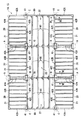
図3には、1階建物ユニット14の概略平面図が示されている。
1階建物ユニット14は、短辺方向に所定間隔おいて平行に配置した1対の建物ユニット20をその長辺方向に3組連結して形成した離隔建物ユニット21と、これら離隔建物ユニット21同士の間に形成された空間22を挟んで離隔建物ユニットの相対向する柱41同士を連結する連結梁70,80とを備えている。ここで、連結梁70は、ユニット式建物10の内部に設けられ、連結梁80は、ユニット式建物10の外周に設けられている。また、これら連結梁70,80同士の間には、小梁90が架け渡されている。
2階建物ユニット15は、1階建物ユニット14と同様に構成されている。
【0018】
図4には、離隔建物ユニット21同士の連結部分A(図3参照)の分解斜視図が示されている。
離隔建物ユニット21同士の連結には、平板状のプレートとしてのシアプレート60が用いられる。シアプレート60が、1階建物ユニット14の隣接する複数の柱頭接合部材45と、これらの柱頭接合部材45の上に配置される2階建物ユニット15の柱脚接合部材46との間に介装されることにより、上下方向および水平方向に隣接する離隔建物ユニット21同士が連結される。
【0019】
具体的には、各離隔建物ユニット21の柱頭接合部材45の上面には、位置決めピン45Aと、挿通孔45Bとが設けられ、柱脚接合部材46の下面には、図示しない位置決め孔と、挿通孔46Bとが設けられている。また、シアプレート60には、位置決め孔60Aと挿通孔60Bとが設けられている。
1階建物ユニット14の柱頭接合部材45の位置決めピン45Aが、シアプレート60の位置決め孔60Aに挿通されて、2階建物ユニット15の柱脚接合部材46の位置決め孔に嵌合されることにより、離隔建物ユニット21同士の位置が決定される。そして、1階建物ユニット14の柱頭接合部材45の挿通孔45B、シアプレート60の挿通孔60Bおよび2階建物ユニット15の柱脚接合部材46の挿通孔46Bにボルト81Aが挿通され、このボルト81Aにナット81Bが螺合されて緊締されることにより、離隔建物ユニット21同士が連結される。
【0020】
図5には、連結梁70の全体斜視図が示されている。
連結梁70は、断面縦長の長方形であって、継目なく一体成形された長尺状の梁本体71と、この梁本体71の両端側で高さ方向中間に略水平に設けられた平板状の接続プレート72と、梁本体71に略垂直に設けられ接続プレート72を支持するエンドプレート73とを備えている。
接続プレート72は、梁本体71にスリットが設けられ、このスリットにシアプレート60が嵌挿されることにより形成されており、複数の位置決め孔60Aおよび挿通孔60Bが設けられている。
エンドプレート73には、接続プレート72を挟んで上下に挿通孔73Cが設けられている。
【0021】
また、連結梁70は、梁本体71の側面に小梁90を支持するための仕口74を備えている。この仕口74は、梁本体71の高さ方向に延びる断面L字形のアングル材を梁本体71に溶接することによって形成されている。
【0022】
図6および図7には、連結梁70と離隔建物ユニット21との連結部分B(図3参照)の分解斜視図および断面図が示されている。
連結梁70の接続プレート72は、シアプレート60と同様に、1階建物ユニット14の隣接する複数の柱頭接合部材45の上端面と、これらの柱頭接合部材45の上に配置される2階建物ユニット15の隣接する複数の柱脚接合部材46の下端面との間に介装されることにより接続される。
具体的には、1階建物ユニット14の柱頭接合部材45の位置決めピン45Aが、接続プレート72の位置決め孔60Aに挿通されて、2階建物ユニット15の柱脚接合部材46の位置決め孔に嵌合される。また、1階建物ユニット14の柱頭接合部材45の挿通孔45B、接続プレート72の挿通孔60Bおよび2階建物ユニット15の柱脚接合部材46の挿通孔46Bにボルト81Aが挿通されてナット81Bで緊締される。
【0023】
また、連結梁70のエンドプレート73は、1階建物ユニット14の隣接する複数の柱頭接合部材45および2階建物ユニット15の隣接する複数の柱脚接合部材46の側面に接続される。
具体的には、1階建物ユニット14の柱頭接合部材45の挿通孔45Cおよびエンドプレート73の挿通孔73C、2階建物ユニット15の柱脚接合部材46の挿通孔46Cおよびエンドプレート73の挿通孔73Cにボルト81Aが挿通されてナット81Bで緊締される。
【0024】
連結梁70の梁本体71は、その両端部が互いに隣接する離隔建物ユニット21同士の間に配置され、梁本体71の梁幅Wは、これら離隔建物ユニット21同士の間の隙間より僅かに狭くなっている。また、梁本体71の梁背Hは、1階建物ユニット14の天井梁42および2階建物ユニット15の床梁43に跨るように設けられている。
【0025】
図8には、連結梁80の全体斜視図が示されている。
連結梁80は、連結梁70と異なり、エンドプレート73は、梁本体71の両端面にその高さ方向に延びる断面L字形のアングル材を溶接することにより形成され、接続プレート72は、エンドプレート73の高さ方向中間にシアプレート60の半分の大きさのプレートを溶接することにより形成されている。
【0026】
図9には、連結梁80と離隔建物ユニット21との連結部分C(図3参照)の断面図が示されている。
連結梁80の接続プレート72は、連結梁70と同様に、1階建物ユニット14の隣接する複数の柱頭接合部材45の上端面と、これらの柱頭接合部材45の上に配置される2階建物ユニット15の隣接する複数の柱脚接合部材46の下端面との間に介装されることにより接続される。同時に、連結梁80のエンドプレート73は、1階建物ユニット14の隣接する複数の柱頭接合部材45および2階建物ユニット15の隣接する複数の柱脚接合部材46の側面に接続される。
その結果、連結梁80の梁本体71は、平面視で天井梁42および床梁43の延長線上に配置される。
【0027】
また、梁本体71の梁背Hは、連結梁70と同様に、1階建物ユニット14の天井梁42および2階建物ユニット15の床梁43に跨るように設けられている。
【0028】
次に、ユニット式建物10の組立手順を説明する。
まず、建物ユニット20および連結梁70,80を工場で製作した後、建築現場に運搬する。現場では、図10に示すように、1対の建物ユニット20をその短辺方向に所定間隔おいて配置し、この1対の建物ユニット20をその長辺方向に3組連結して離隔建物ユニット21として、1階建物ユニット14を形成する。
次に、隣接する離隔建物ユニット21同士をシアプレート60で連結し、所定間隔おいて相対向する離隔建物ユニット同士を連結梁70,80で連結して、これら連結梁70,80同士の間に小梁90を架け渡す。
【0029】
続いて、シアプレート60および連結梁70,80の接続プレート72を挟み込みながら、建物ユニット20を各離隔建物ユニット21上に積層して2階建物ユニット15を形成し、連結梁70,80、1階建物ユニット14および2階建物ユニット15をボルト81Aおよびナット81Bで連結する。
次に、2階建物ユニット15についても、1階建物ユニット14と同様に、連結梁70,80および小梁90を架け渡し、この2階建物ユニット15の上に屋根13を取り付ける。
【0030】
したがって、本実施形態によれば以下の効果がある。
(1)連結梁70,80直下の空間22を居住空間として利用できるため、ユニット式建物10を構成する建物ユニット20の数量を減らすことができるから、ユニット式建物10の製造コストを低減できる。また、離隔建物ユニット21同士の間隔に対応させて連結梁70,80の梁本体71の長さ寸法を設定するだけで、多様な平面形状のユニット式建物を建築できるから、種々の敷地形状に応じて建物を建築できる。
【0031】
(2)柱41の上端面および下端面に接続プレート72を接続したので、2階では、屋根13の下面と1階建物ユニット14の柱41の上端面との間に接続プレート72が挟み込まれ、1階では、2階建物ユニット15の柱41の下端面と1階建物ユニット14の柱41の上端面との間に接続プレート72が挟み込まれるから、連結梁70,80に作用する荷重を梁本体71および接続プレート72を介して、離隔建物ユニット21のフレーム40に確実に伝達できるから、連結梁70,80と離隔建物ユニット21との接続部分を何ら補強する必要がないうえに、連結梁70,80と離隔建物ユニット21との接続部分にエキスパンションジョイントのような複雑な納まりが必要がないため、容易に施工できる。
【0032】
(3)エンドプレート73を介して接続プレート72が梁本体71に支持されるから、接続プレート72の変形を抑制して、梁本体71の垂直荷重に対する剛性をさらに向上できる。
また、エンドプレート73を離隔建物ユニット21の柱頭接合部材45および柱脚接合部材46の側面に接続したので、連結梁70,80を離隔建物ユニット21にさらに強固に接続できる。
【0033】
(4)連結梁70の梁本体71の両端部を離隔建物ユニット21同士の間に配置したので、連結梁70に垂直荷重または水平荷重が作用して変形しようとしても、離隔建物ユニット21の側面に押圧されることによりその変形が抑制されるから、ユニット式建物10の構造耐力を向上できる。
【0034】
(5)連結梁80の梁本体71を平面視で天井梁42および床梁43の延長線上に配置したので、ユニット式建物10の外周に沿って連結梁80を設けても、連結梁80がユニット式建物10の外周側に突出しないから、外装材を容易に取り付けることができる。
【0035】
(6)連結梁70,80の梁本体71の梁背Hを1階建物ユニット14の天井梁42および2階建物ユニット15の床梁43に跨って設けたので、梁本体71の垂直荷重に対する剛性を向上できる。
【0036】
(7)連結梁70,80の梁本体71の側面に仕口74を設けたので、この仕口74に小梁90を取り付け、この小梁90に内装材を支持させることによって、内装工事を容易に行うことができる。
【0037】
(8)連結梁70の梁本体71に設けられたスリットにシアプレート60を嵌挿して接続プレート72を形成したので、梁本体にプレートを溶接する場合に比べ、接合部分の信頼性が高く施工手間もかからないから、接続プレート72を確実かつ容易に形成できる。
【0038】
なお、本発明は前記実施形態に限定されるものではなく、本発明の目的を達成できる範囲での変形、改良等は本発明に含まれるものである。
例えば、本実施形態では、建物ユニット20を短辺方向に所定間隔おいて平行に配置して離隔建物ユニット21を形成したが、これに限らず、図11に示すように、建物ユニット20同士を平面視で傾斜して配置してもよい。すなわち、離隔建物ユニット21同士の間に形成された空間22は平面台形状となり、この空間22を挟んで離隔建物ユニットの相対向する柱41同士を連結する連結梁70および連結梁80の梁本体71の長さはそれぞれ異なっている。
このようにしても、前記実施形態で述べた(1)〜(8)と同様の効果がある。
【0039】
【発明の効果】
本発明のユニット式建物によれば、次のような効果が得られる。
請求項1に記載のユニット式建物によれば、連結梁直下の空間を居住空間として利用できるため、ユニット式建物を構成する建物ユニットの数量を減らすことができるから、ユニット式建物の製造コストを低減できる。また、離隔建物ユニット同士の間隔に対応させて連結梁の梁本体の長さ寸法を設定するだけで、多様な平面形状のユニット式建物を建築できるから、種々の敷地形状に応じて建物を建築できる。さらに、柱の上端面および下端面のうち少なくとも一方に接続プレートを接続したので、連結梁に作用する荷重を梁本体および接続プレートを介して、離隔建物ユニットの構造体に確実に伝達でき、連結梁と離隔建物ユニットとの接続部分を何ら補強する必要がないうえに、連結梁と離隔建物ユニットとの接続部分にエキスパンションジョイントのような複雑な納まりが必要がないため、容易に施工できる。また、連結梁の梁本体の梁背を下側建物ユニットの天井梁および上側建物ユニットの床梁に跨って設けたので、梁本体の垂直荷重に対する剛性を向上できる。
【0040】
請求項2に記載のユニット式建物によれば、エンドプレートを介して接続プレートが梁本体に支持されるから、接続プレートの変形を抑制して、梁本体の垂直荷重に対する剛性をさらに向上できる。また、エンドプレートを離隔建物ユニットの柱の側面に接続したので、連結梁を離隔建物ユニットに強固に接続できる。
【0041】
請求項3に記載のユニット式建物によれば、連結梁の梁本体の両端部を離隔建物ユニットとこの離隔建物ユニットに隣接する建物ユニットとの間に配置したので、連結梁に垂直荷重または水平荷重が作用して変形しようとしても、離隔建物ユニットまたは建物ユニットの側面に押圧されることによりその変形が抑制されるから、ユニット式建物の構造耐力を向上できる。
【0042】
請求項4に記載のユニット式建物によれば、連結梁の梁本体を平面視で天井梁および床梁の延長線上に配置したので、ユニット式建物の外周に沿って連結梁を設けても、連結梁がユニット式建物の外周側に突出しないから、外装材を容易に取り付けることができる。
【0044】
請求項5に記載のユニット式建物によれば、連結梁の梁本体の側面に仕口を設けたので、この仕口に小梁を取り付け、この小梁に内装材を支持させることによって、内装工事を容易に行うことができる。
【0045】
請求項6に記載のユニット式建物によれば、連結梁の梁本体に設けられたスリットにプレートを嵌挿して接続プレートを形成したので、梁本体にプレートを溶接する場合に比べ、接合部分の信頼性が高く施工手間もかからないから、接続プレートを確実かつ容易に形成できる。
【図面の簡単な説明】
【図1】本発明の一実施形態に係るユニット式建物を示す全体斜視図である。
【図2】前記実施形態に係る建物ユニットのフレームの斜視図である。
【図3】前記実施形態に係るユニット式建物の概略平面図である。
【図4】前記実施形態に係る離隔建物ユニット同士の連結部分の分解斜視図である。
【図5】前記実施形態に係るユニット式建物の内部に設けられた連結梁の全体斜視図である。
【図6】前記実施形態に係るユニット式建物の内部に設けられた連結梁と離隔建物ユニットとの連結部分の分解斜視図である。
【図7】前記実施形態に係るユニット式建物の内部に設けられた連結梁と離隔建物ユニットとの連結部分の図3中VII-VII線断面図である。
【図8】前記実施形態に係るユニット式建物の外周に設けられた連結梁の全体斜視図である。
【図9】前記実施形態に係るユニット式建物の外周に設けられた連結梁と離隔建物ユニットとの連結部分の図3中IX-IX線断面図である。
【図10】前記実施形態に係るユニット式建物を組み立てる方法を説明するための分解斜視図である。
【図11】本発明の変形例に係るユニット式建物を示す概略平面図である。
【符号の説明】
10 ユニット式建物
14 下側建物ユニットとしての1階建物ユニット
15 上側建物ユニットとしての2階建物ユニット
20 建物ユニット
21 離隔建物ユニット
22 空間
40 フレーム
41 柱
42 天井梁
43 床梁
60 プレートとしてのシアプレート
70,80 連結梁
71 梁本体
72 接続プレート
73 エンドプレート
74 仕口
90 小梁[0001]
BACKGROUND OF THE INVENTION
The present invention relates to a unit type building provided with a connecting beam for connecting box-shaped building units arranged at predetermined intervals.
[0002]
[Background]
Conventionally, a unit type building constructed by connecting a plurality of box-shaped building units manufactured in a factory at a construction site has been used.
As a building unit forming this unit type building, one having a box-shaped frame in which upper and lower ends of pillars at four corners are connected by a ceiling beam and a floor beam is generally used. The frame has a ceiling surface material supported by the ceiling beam, an interior material such as a floor surface material supported by the floor beam and a partition wall partitioning the room, and an exterior material such as an outer wall formed of lightweight cellular concrete. It is assembled with.
According to such a unit-type building, after the building unit is manufactured by performing the attaching work of the interior material and the exterior material to the box-shaped frame in the factory, the building unit is simply transported to the site and the connecting work is performed. Since the building is completed, the work on the construction site is greatly reduced and the construction can be completed in a short period of time.
[0003]
By the way, since such a unit type building is formed by combining a plurality of building units, the size of the building has been set by increasing / decreasing each width dimension or length dimension of the building unit. Therefore, the size of the building cannot be set corresponding to the site shape, and it may be difficult to effectively use the site.
Moreover, since all the interior space of a unit type building is formed with a building unit, it has structural proof strength more than the structural proof strength required for a design, As a result, the cost was high.
[0004]
In order to solve the above problems, a method of dividing a unit type building into a plurality of building parts and connecting these building parts via an expansion joint is known (Japanese Patent Laid-Open No. 9-67868). Here, the expansion joint is a beam that connects the wall surfaces of the building parts and can follow the relative displacement of each building part.
According to Japanese Patent Application Laid-Open No. 9-67868, it is possible to construct unit buildings of various planar shapes simply by setting the length dimension of the expansion joint corresponding to the interval between the building parts. The building can be constructed according to the situation, and the effective use of the site can be realized. Moreover, since the space immediately under the expansion joint can be used as a living space, the number of building units constituting the unit type building can be reduced, and the manufacturing cost of the unit type building can be reduced.
[0005]
[Problems to be solved by the invention]
However, in the above-described method, since the expansion joint is connected to the wall surface, it has been difficult to smoothly transmit the load applied to the expansion joint to the structure of each building portion. Therefore, it is necessary to reinforce the connection part between the expansion joint and each building part, and the accommodation for moving the expansion part freely becomes complicated, which requires construction work.
[0006]
The objective of this invention is providing the unit type building provided with the connection beam which can be constructed easily.
[0007]
[Means for Solving the Problems]
In order to achieve the above object, the unit type building of the present invention adopts the following configuration.
The present invention will be described with reference to the drawings. A unit building 10 according to claim 1 includes a
The upper end position between the pillars of a pair of lower spaced building units, and among the lower end position between the pillars of the pair of upper spaced building unit comprises a pair of connecting
[0008]
According to this invention, since the space immediately below the connecting beam can be used as a living space, the number of building units constituting the unit type building can be reduced, so that the manufacturing cost of the unit type building can be reduced. In addition, it is possible to build unit-type buildings with various planar shapes simply by setting the length of the beam body of the connecting beam in correspondence with the distance between the separate building units, so the building can be built according to various site shapes. it can.
Furthermore, since connecting at least one connection plate of the upper end face and lower end face of the column, For example, the intermediate floor on pillars spaced building unit of the lower end surface and the lower floor of the column the separation building units upstairs Since the connecting plate is sandwiched between the end face, the load acting on the connecting beam can be reliably transmitted to the structure of the remote building unit via the beam body and the connecting plate, and the connecting portion between the connecting beam and the remote building unit. It is not necessary to reinforce anything, and it is not necessary to have a complicated housing like an expansion joint at the connecting part between the connecting beam and the remote building unit, so that it can be easily constructed.
Moreover, since the beam back of the beam main body of the connecting beam is provided across the ceiling beam of the lower building unit and the floor beam of the upper building unit, the rigidity of the beam main body against the vertical load can be improved.
[0009]
The unit type building according to claim 2 is the unit type building according to claim 1, wherein the connecting beam is provided on the beam main body and supports the connection plate and is connected to a side surface of a column of the remote building unit. An
According to this invention, since the connection plate is supported by the beam main body via the end plate, the deformation of the connection plate can be suppressed and the rigidity of the beam main body with respect to the vertical load can be further improved.
Further, since the end plate is connected to the side surface of the column of the remote building unit, the connecting beam can be firmly connected to the remote building unit.
[0010]
The unit building according to claim 3 is the unit building according to claim 1 or 2, wherein the beam main body of the connecting beam is adjacent to the remote building unit and the remote building unit at both ends thereof. It is arrange | positioned between.
According to the present invention, since both ends of the beam main body of the connecting beam are arranged between the remote building unit and the building unit adjacent to the remote building unit, the vertical or horizontal load acts on the connecting beam to be deformed. However, since the deformation | transformation is suppressed by being pressed on the side surface of a separated building unit or a building unit, the structural yield strength of a unit type building can be improved.
[0011]
The unit building according to claim 4 is the unit building according to claim 1 or 2, wherein the beam main body of the connecting beam is arranged on an extension line of the ceiling beam and the floor beam in a plan view. It is characterized by that.
According to this invention, since the beam main body of the connecting beam is arranged on the extension line of the ceiling beam and the floor beam in a plan view, even if the connecting beam is provided along the outer periphery of the unit type building, the connecting beam is the unit type building. Since it does not protrude to the outer peripheral side, the exterior material can be easily attached.
[0013]
The unitary building according to claim 5, in unitary building according to any one of claims 1 to 4, the beam body of the connecting beam,
According to this invention, since the joint is provided on the side surface of the beam main body of the connecting beam, the interior work can be easily performed by attaching the small beam to the joint and supporting the interior material on the small beam. it can.
[0014]
The unit building according to claim 6 is the unit building according to any one of claims 1 to 5 , wherein the connection plate is formed by inserting a
According to this invention, since the connection plate is formed by inserting the plate into the slit provided in the beam main body of the connecting beam, compared with the case where the plate is welded to the beam main body, the reliability of the joint portion is high, and the construction labor is also reduced. Since it does not start, a connection plate can be formed reliably and easily.
[0015]
DETAILED DESCRIPTION OF THE INVENTION
Hereinafter, embodiments of the present invention will be described with reference to the drawings.
FIG. 1 is an overall perspective view of a unit building 10 according to the present embodiment. The unit building 10 includes a
Among these, the building
[0016]
The first
As shown in FIG. 2, the
There are two types of ceiling beams 42, short-
[0017]
FIG. 3 shows a schematic plan view of the first
The first-
The second
[0018]
FIG. 4 shows an exploded perspective view of a connecting portion A (see FIG. 3) between the
A
[0019]
Specifically, a
The
[0020]
FIG. 5 shows an overall perspective view of the connecting
The connecting
The
The
[0021]
Further, the connecting
[0022]
6 and 7 show an exploded perspective view and a cross-sectional view of a connecting portion B (see FIG. 3) between the connecting
Similar to the
Specifically, the
[0023]
In addition, the
Specifically, the
[0024]
The beam
[0025]
FIG. 8 is an overall perspective view of the connecting
Unlike the connecting
[0026]
FIG. 9 shows a cross-sectional view of a connecting portion C (see FIG. 3) between the connecting
As with the connecting
As a result, the beam
[0027]
Further, the beam back H of the beam
[0028]
Next, the assembly procedure of the unit type building 10 will be described.
First, the
Next, the
[0029]
Subsequently, while sandwiching the
Next, similarly to the first-
[0030]
Therefore, according to this embodiment, there are the following effects.
(1) Since the
[0031]
(2) Since the
[0032]
(3) Since the
Further, since the
[0033]
(4) Since both ends of the beam
[0034]
(5) Since the beam
[0035]
(6) Since the beam back H of the beam
[0036]
(7) Since the joint 74 is provided on the side surface of the beam
[0037]
(8) Since the
[0038]
It should be noted that the present invention is not limited to the above-described embodiment, and modifications, improvements, etc. within a scope that can achieve the object of the present invention are included in the present invention.
For example, in the present embodiment, the
Even if it does in this way, there exists an effect similar to (1)-(8) described in the said embodiment.
[0039]
【The invention's effect】
According to the unit type building of the present invention, the following effects can be obtained.
According to the unit type building according to claim 1, since the space immediately below the connecting beam can be used as a living space, the number of building units constituting the unit type building can be reduced. Can be reduced. In addition, it is possible to build unit-type buildings with various planar shapes simply by setting the length of the beam body of the connecting beam in correspondence with the distance between the separate building units, so the building can be built according to various site shapes. it can. In addition, since the connection plate is connected to at least one of the upper and lower end surfaces of the column, the load acting on the connection beam can be reliably transmitted to the structure of the remote building unit via the beam body and connection plate. Since it is not necessary to reinforce the connection part between the beam and the remote building unit, and the connection part between the connecting beam and the remote building unit does not need a complicated fit like an expansion joint, it can be easily constructed. Moreover, since the beam back of the beam main body of the connecting beam is provided across the ceiling beam of the lower building unit and the floor beam of the upper building unit, the rigidity of the beam main body against the vertical load can be improved.
[0040]
According to the unit type building of the second aspect, since the connection plate is supported by the beam body via the end plate, the deformation of the connection plate can be suppressed and the rigidity of the beam body with respect to the vertical load can be further improved. Further, since the end plate is connected to the side surface of the column of the remote building unit, the connecting beam can be firmly connected to the remote building unit.
[0041]
According to the unit type building of the third aspect, since both ends of the beam main body of the connecting beam are arranged between the remote building unit and the building unit adjacent to the remote building unit, a vertical load or horizontal Even if the load is applied to be deformed, the deformation is suppressed by being pressed against the remote building unit or the side surface of the building unit, so that the structural strength of the unit type building can be improved.
[0042]
According to the unit type building according to claim 4, since the beam main body of the connecting beam is arranged on the extension line of the ceiling beam and the floor beam in a plan view, even if the connecting beam is provided along the outer periphery of the unit type building, Since the connecting beam does not protrude to the outer peripheral side of the unit type building, the exterior material can be easily attached.
[0044]
According to the unit type building according to claim 5 , since the joint is provided on the side surface of the beam body of the connecting beam, the interior is provided by attaching the small beam to the joint and supporting the interior material on the small beam. Construction can be done easily.
[0045]
According to the unit type building of the sixth aspect , since the connection plate is formed by inserting the plate into the slit provided in the beam main body of the connecting beam, compared with the case of welding the plate to the beam main body, The connection plate can be reliably and easily formed because it is highly reliable and does not require labor.
[Brief description of the drawings]
FIG. 1 is an overall perspective view showing a unit building according to an embodiment of the present invention.
FIG. 2 is a perspective view of a frame of the building unit according to the embodiment.
FIG. 3 is a schematic plan view of a unit building according to the embodiment.
FIG. 4 is an exploded perspective view of a connecting portion between remote building units according to the embodiment.
FIG. 5 is an overall perspective view of a connecting beam provided in the unit building according to the embodiment.
FIG. 6 is an exploded perspective view of a connecting portion between a connecting beam and a remote building unit provided in the unit type building according to the embodiment.
7 is a cross-sectional view taken along the line VII-VII in FIG. 3 of a connecting portion between a connecting beam and a remote building unit provided in the unit type building according to the embodiment.
FIG. 8 is an overall perspective view of a connecting beam provided on the outer periphery of the unit type building according to the embodiment.
9 is a cross-sectional view taken along the line IX-IX in FIG. 3 of a connecting portion between a connecting beam and a remote building unit provided on the outer periphery of the unit type building according to the embodiment.
FIG. 10 is an exploded perspective view for explaining a method of assembling a unit building according to the embodiment.
FIG. 11 is a schematic plan view showing a unit building according to a modification of the present invention.
[Explanation of symbols]
DESCRIPTION OF SYMBOLS 10 Unit type building 14 1st
Claims (6)
前記下側建物ユニットは、前記建物ユニットが所定間隔おいて配置されることにより形成された少なくとも一対の下側の離隔建物ユニットを有し、
前記上側建物ユニットは、前記下側の離隔建物ユニットに積層された少なくとも一対の上側の離隔建物ユニットを有し、
前記一対の下側の離隔建物ユニットの柱の上端位置同士、および前記一対の上側の離隔建物ユニットの柱の下端位置同士のうち、少なくとも一方を連結する一対の連結梁を備え、
前記連結梁は、長尺状の梁本体と、この梁本体の両端側に設けられて前記下側の離隔建物ユニットの柱の上端面、および前記上側の離隔建物ユニットの柱の下端面のうち少なくとも一方に接続される接続プレートとを備え、
前記梁本体は、その梁背が前記下側の離隔建物ユニットの天井梁および前記上側の離隔建物ユニットの床梁に跨って設けられ、
前記一対の連結梁の間には、小梁が架け渡されていることを特徴とするユニット式建物。A unit type building comprising an upper building unit and a lower building unit in which building units having a frame formed in a box shape by connecting upper and lower ends of pillars at four corners with a ceiling beam and a floor beam,
The lower building unit, said building unit has a lower separation building unit of the at least one pair formed by being arranged in advance a predetermined distance,
The upper building unit has at least a pair of upper separated building units stacked on the lower separated building unit,
The upper end position between the pillars of a pair of lower spaced building units, and among the lower end position between the pillars of the pair of upper spaced building unit comprises a pair of connecting beams connecting at least one,
The connecting beam includes an elongated beam body, of the bottom surface of the upper end surface, and the pillar of the upper separation building unit pillars spaced building unit of the lower provided at both ends of the beam body A connection plate connected to at least one of
The beam main body is provided with the beam back straddling the ceiling beam of the lower separated building unit and the floor beam of the upper separated building unit,
A unit type building characterized in that a small beam is bridged between the pair of connecting beams .
前記連結梁は、前記梁本体に設けられ前記接続プレートを支持するとともに前記離隔建物ユニットの柱の側面に接続されるエンドプレートを備えていることを特徴とするユニット式建物。In the unit type building of Claim 1,
The unit beam is provided with an end plate that is provided on the beam main body, supports the connection plate, and is connected to a side surface of a column of the remote building unit.
前記連結梁の梁本体は、その両端部が前記離隔建物ユニットとこの離隔建物ユニットに隣接する建物ユニットとの間に配置されていることを特徴とするユニット式建物。In the unit type building of Claim 1 or 2,
The unit-type building, wherein both ends of the beam main body of the connecting beam are arranged between the remote building unit and a building unit adjacent to the remote building unit.
前記連結梁の梁本体は、平面視で前記天井梁および前記床梁の延長線上に配置されていることを特徴とするユニット式建物。In the unit type building of Claim 1 or 2,
The unit type building characterized in that a beam main body of the connecting beam is arranged on an extension line of the ceiling beam and the floor beam in a plan view.
前記連結梁の梁本体は、その側面に前記小梁を支持するための仕口を備えていることを特徴とするユニット式建物。In the unit type building in any one of Claim 1 to 4,
The unit building according to claim 1, wherein a beam body of the connecting beam has a joint for supporting the small beam on a side surface thereof.
前記接続プレートは、前記梁本体に設けられたスリットにプレートが嵌挿されて形成されていることを特徴とするユニット式建物。In the unit type building in any one of Claim 1 to 5,
The connection plate is formed by inserting a plate into a slit provided in the beam main body.
Priority Applications (1)
| Application Number | Priority Date | Filing Date | Title |
|---|---|---|---|
| JP2002001714A JP3893061B2 (en) | 2002-01-08 | 2002-01-08 | Unit building |
Applications Claiming Priority (1)
| Application Number | Priority Date | Filing Date | Title |
|---|---|---|---|
| JP2002001714A JP3893061B2 (en) | 2002-01-08 | 2002-01-08 | Unit building |
Publications (2)
| Publication Number | Publication Date |
|---|---|
| JP2003201736A JP2003201736A (en) | 2003-07-18 |
| JP3893061B2 true JP3893061B2 (en) | 2007-03-14 |
Family
ID=27641776
Family Applications (1)
| Application Number | Title | Priority Date | Filing Date |
|---|---|---|---|
| JP2002001714A Expired - Fee Related JP3893061B2 (en) | 2002-01-08 | 2002-01-08 | Unit building |
Country Status (1)
| Country | Link |
|---|---|
| JP (1) | JP3893061B2 (en) |
Families Citing this family (4)
| Publication number | Priority date | Publication date | Assignee | Title |
|---|---|---|---|---|
| JP4759240B2 (en) * | 2004-09-06 | 2011-08-31 | ミサワホーム株式会社 | Building unit connection structure |
| JP4881456B2 (en) * | 2010-03-23 | 2012-02-22 | ミサワホーム株式会社 | Building unit connection structure |
| JP4801226B1 (en) * | 2010-04-01 | 2011-10-26 | 積水化学工業株式会社 | Unit building and construction method of unit building |
| JP2013079545A (en) * | 2011-10-05 | 2013-05-02 | Misawa Homes Co Ltd | Unit building and construction method for unit building |
-
2002
- 2002-01-08 JP JP2002001714A patent/JP3893061B2/en not_active Expired - Fee Related
Also Published As
| Publication number | Publication date |
|---|---|
| JP2003201736A (en) | 2003-07-18 |
Similar Documents
| Publication | Publication Date | Title |
|---|---|---|
| JP4858921B2 (en) | Attached structures and unit buildings | |
| JP3893061B2 (en) | Unit building | |
| JP2002097722A (en) | Unit type building and corner reinforcing material therefor | |
| JP4328455B2 (en) | Unit building | |
| JP3831545B2 (en) | Unit building | |
| JP4717245B2 (en) | Unit buildings and corner reinforcements for unit buildings | |
| JP3995083B2 (en) | Unit building | |
| JP4749611B2 (en) | Unit type building and its construction method | |
| JP3887233B2 (en) | Unit building | |
| JP2001164658A (en) | Beam joining structure and unit building | |
| JP6288950B2 (en) | Building unit connection structure | |
| JP5000881B2 (en) | Unit type building and construction method of the unit type building | |
| JP3766775B2 (en) | Reinforced beams and unit buildings | |
| JP4700178B2 (en) | Unit building | |
| JP3780278B2 (en) | Reinforced beams and unit buildings | |
| JP4146593B2 (en) | Building unit connection structure | |
| JP3545492B2 (en) | Beam connection structure | |
| JP2008121421A (en) | Reinforcing beam, unit type building, and execution method of unit type building | |
| JP2002021189A (en) | Unit building | |
| JP4381631B2 (en) | Unit building shed structure | |
| JP4104246B2 (en) | Unit building and its construction method | |
| JP3771782B2 (en) | Unit building | |
| JP3707941B2 (en) | Unit building and its construction method | |
| JP3878632B2 (en) | Reinforced beams and unit buildings | |
| JP5431245B2 (en) | Unit building |
Legal Events
| Date | Code | Title | Description |
|---|---|---|---|
| A621 | Written request for application examination |
Free format text: JAPANESE INTERMEDIATE CODE: A621 Effective date: 20050105 |
|
| A977 | Report on retrieval |
Free format text: JAPANESE INTERMEDIATE CODE: A971007 Effective date: 20060818 |
|
| A131 | Notification of reasons for refusal |
Free format text: JAPANESE INTERMEDIATE CODE: A131 Effective date: 20060829 |
|
| A521 | Request for written amendment filed |
Free format text: JAPANESE INTERMEDIATE CODE: A523 Effective date: 20061030 |
|
| TRDD | Decision of grant or rejection written | ||
| A01 | Written decision to grant a patent or to grant a registration (utility model) |
Free format text: JAPANESE INTERMEDIATE CODE: A01 Effective date: 20061128 |
|
| A61 | First payment of annual fees (during grant procedure) |
Free format text: JAPANESE INTERMEDIATE CODE: A61 Effective date: 20061208 |
|
| R150 | Certificate of patent or registration of utility model |
Free format text: JAPANESE INTERMEDIATE CODE: R150 Ref document number: 3893061 Country of ref document: JP Free format text: JAPANESE INTERMEDIATE CODE: R150 |
|
| FPAY | Renewal fee payment (event date is renewal date of database) |
Free format text: PAYMENT UNTIL: 20091215 Year of fee payment: 3 |
|
| S111 | Request for change of ownership or part of ownership |
Free format text: JAPANESE INTERMEDIATE CODE: R313111 |
|
| FPAY | Renewal fee payment (event date is renewal date of database) |
Free format text: PAYMENT UNTIL: 20091215 Year of fee payment: 3 |
|
| R350 | Written notification of registration of transfer |
Free format text: JAPANESE INTERMEDIATE CODE: R350 |
|
| FPAY | Renewal fee payment (event date is renewal date of database) |
Free format text: PAYMENT UNTIL: 20101215 Year of fee payment: 4 |
|
| FPAY | Renewal fee payment (event date is renewal date of database) |
Free format text: PAYMENT UNTIL: 20101215 Year of fee payment: 4 |
|
| FPAY | Renewal fee payment (event date is renewal date of database) |
Free format text: PAYMENT UNTIL: 20111215 Year of fee payment: 5 |
|
| FPAY | Renewal fee payment (event date is renewal date of database) |
Free format text: PAYMENT UNTIL: 20121215 Year of fee payment: 6 |
|
| FPAY | Renewal fee payment (event date is renewal date of database) |
Free format text: PAYMENT UNTIL: 20121215 Year of fee payment: 6 |
|
| FPAY | Renewal fee payment (event date is renewal date of database) |
Free format text: PAYMENT UNTIL: 20131215 Year of fee payment: 7 |
|
| R250 | Receipt of annual fees |
Free format text: JAPANESE INTERMEDIATE CODE: R250 |
|
| LAPS | Cancellation because of no payment of annual fees |