JP3609412B2 - Chain drive mechanism for built toy system - Google Patents
Chain drive mechanism for built toy system Download PDFInfo
- Publication number
- JP3609412B2 JP3609412B2 JP52121895A JP52121895A JP3609412B2 JP 3609412 B2 JP3609412 B2 JP 3609412B2 JP 52121895 A JP52121895 A JP 52121895A JP 52121895 A JP52121895 A JP 52121895A JP 3609412 B2 JP3609412 B2 JP 3609412B2
- Authority
- JP
- Japan
- Prior art keywords
- chain
- link element
- side wall
- drive mechanism
- toy system
- Prior art date
- Legal status (The legal status is an assumption and is not a legal conclusion. Google has not performed a legal analysis and makes no representation as to the accuracy of the status listed.)
- Expired - Lifetime
Links
Images


Classifications
-
- A—HUMAN NECESSITIES
- A63—SPORTS; GAMES; AMUSEMENTS
- A63H—TOYS, e.g. TOPS, DOLLS, HOOPS OR BUILDING BLOCKS
- A63H33/00—Other toys
- A63H33/04—Building blocks, strips, or similar building parts
- A63H33/06—Building blocks, strips, or similar building parts to be assembled without the use of additional elements
- A63H33/08—Building blocks, strips, or similar building parts to be assembled without the use of additional elements provided with complementary holes, grooves, or protuberances, e.g. dovetails
-
- A—HUMAN NECESSITIES
- A63—SPORTS; GAMES; AMUSEMENTS
- A63H—TOYS, e.g. TOPS, DOLLS, HOOPS OR BUILDING BLOCKS
- A63H33/00—Other toys
- A63H33/04—Building blocks, strips, or similar building parts
- A63H33/042—Mechanical, electrical, optical, pneumatic or hydraulic arrangements; Motors
-
- Y—GENERAL TAGGING OF NEW TECHNOLOGICAL DEVELOPMENTS; GENERAL TAGGING OF CROSS-SECTIONAL TECHNOLOGIES SPANNING OVER SEVERAL SECTIONS OF THE IPC; TECHNICAL SUBJECTS COVERED BY FORMER USPC CROSS-REFERENCE ART COLLECTIONS [XRACs] AND DIGESTS
- Y10—TECHNICAL SUBJECTS COVERED BY FORMER USPC
- Y10S—TECHNICAL SUBJECTS COVERED BY FORMER USPC CROSS-REFERENCE ART COLLECTIONS [XRACs] AND DIGESTS
- Y10S59/00—Chain, staple, and horseshoe making
- Y10S59/90—Plastic
Landscapes
- Toys (AREA)
- Gears, Cams (AREA)
Abstract
Description
関連出願
本出願は、グリックマンに対して付与され、現在コネクター セット リミテッド パートナーシップ(アメリカ合衆国ペンシルヴェニア州ハットフィールド所在)によって所有されている米国特許第5,061,219号、第5,199,919号、第5,346,420号、および第5,137,486号の主題と関連する。従って、それら特許の開示内容をその都度言及することによって本明細書に組み入れることにする。
本発明の背景および開示
本発明は、新規な構築玩具システム用チェーン駆動機構に関し、構築玩具システムに組み付けられて駆動力入力部から離れた所に位置する可動部を駆動するのに使用され、或る位置から別の位置に構築構成要素を搬送する等のためのものである。本発明のチェーン駆動機構は、上記した米国特許の構成要素に組み入れて連結して使用した場合、最も有用である。
本発明のチェーン駆動機構には新規な構造のチェーン用シンク要素が含まれ、各リンク要素は造形プラスチックを射出成型して成るもので、全体的にU字状の形状をしている。このリンク要素は一対の対向離間側壁部を備え、該側壁部の遊端側に外周辺に開口する切り欠きが設けられている。他方、U字状の同リンク要素の基部には、隣りに配列される別のリンク要素の切り欠き側壁部を嵌め入れ組み合わせる為の断面狭小の環状保持溝を形成する筒状支承部が備えられている。一旦その様な嵌め入れ組み合わせが完了されると、隣接するリンク要素同士は半恒久的に連結されるが、従来のリンク連結チェーンと同じように横断方向軸を中心に容易に回動し得る。この様な構成によって個別の応用に適した長さを有するように駆動用チェーンが合成され得る。勿論、分解も同じく効率的に行われる。このチェーン合成物は堅牢かつ極めて軽量で、以下に明らかにされる様に優れて万能的である。
本発明のとりわけ好ましい実施例に於いては、個々のチェーン用リンク要素の基部に該基部から外側方に突出し、かつ上記支承部と同軸の左右一対の駆動ピンが設けられている。連続的に繋げたリンク要素のうち隣り同士のものの双方の駆動ピンの間の間隔は駆動歯車の各歯の所定数の歯の間の間隔と対応している。又、本発明の好ましい実施例に於いては、駆動歯車を一対用いて互いに所定スペース隔ててシャフト上に装着されている。この所定スペースは、チェーン用リンク要素の一対の対向離間側壁部によって形成される最大総体幅と等しい。駆動歯車はそれぞれ支持シャフトに固着され、チェーンとシャフトとの間で駆動的連係を担っている。左右一対の駆動ピンは、チェーンが進められるに伴って前方の駆動歯車の連続歯の間の溝に陥り、チェーンとシャフトとの間に於ける好ましい形態の駆動的連係に役だっている。
本発明のもう一つの好ましい実施例に於いては、各チェーン用リンク要素の基部には、上記した筒状支承部に加えて、横断方向に溝が形成された中央連結部が備えられている。その溝は、上記した特許に開示されたタイプの接続具要素を嵌め入れて組み合わせるのに便宜を与える為のものである。接続具要素をチェーン合成体の所定のリンク要素と組み合わせることによって、搬送構築物で部品を移動させたり、ローラーコースター等の傾斜に沿って乗物を昇らせたりなどの追加的駆動機能を提供することが出来る。
本発明の上記した又は他の特長及び利点を一層理解するには、本発明の実施例の下記の詳細な説明、及び添付図面を参照すべきである。
【図面の簡単な説明】
図1は、本発明の特長を具備する新規なチェーン用リンク要素の平面図である。
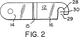
図2は、図1のチェーン用リンク要素の側面図である。
図3は、図1の矢視線3−3についての概略横断図である。
図4は、図1のチェーン用リンク要素を複数個連結して成るチェーン合成体を示す部分平面図で、チェーン合成体をスプロケット複合体に対して駆動および被駆動の関係で配置している。
図5は、図4のチェーン合成体の側面図である。
図6は、図5の矢視線6−6についての概略縦断図で、スプロケット複合体の一部を形成する平歯車の構造の詳細を示す。
図7は、平歯車の一部の拡大部分図である。
図8は、図3と同様な縦断図であって、チェーン用リンク要素に対して接続具要素を組み合わせたものを示す。
図9は、スプロケット複合体をシャフトに連結して一体に駆動させるために利用された駆動ブロックの斜視図である。
図10は、図4の矢視線10−10についての概略縦断図で、駆動ブロックがシャフトに装着された状態を示す。
図11は、本発明のチェーン駆動機構に於けるスプロケット支持シャフトとして有用な支柱状構築玩具要素の側面図である。
発明を実施するための最良の形態
図面を参照して説明すると、図1に於ける参照番号10はチェーン用リンク要素を全体的に示す。このリンク要素は、造形プラスチック材、好ましくはポリプロピレンを射出成型したもので、全体的にU字状の形状を有し、参照番号13により包括的に示す一体的基部によって強固に端部において連結される左右一対の対向離間側壁部11、12を含んでいる。側壁部11、12はそれぞれ全体的に薄くて平らな形状のもので、基端部14、段差部15および突出遊端部16から成る。段差部15は、遊端部16の外側表面17が側壁部の基端部14の内側表面18と実質的に同一平面上に存在するように形成されている。これによって、以下に於いて明らかになるように連続リンク要素の端部対端部の組み合わせが容易になる。
チェーン用U字状リンク要素10の基部13は、側壁部11、12と一体に射出成型されて強固に結合され、各側壁部の基端部14と直接面する筒状支承部19、20を備えている。これら支承部19、20の間に連結部21が設置されている。連結部の上方表面と下方表面とには連結溝22が形成されている。この連結部は、後に説明する外部要素を取り付けるために利用される。
図1から明らかなように、連結部21は支承部19、20と同軸上に配され、支承部より大きな外形寸法を有する。従って、側壁基端部14の内側表面と連結部21の対向端面との間に環状保持溝24、25が形成される。
駆動ピン26、27がチェーン用リンク要素の両側から外方に、かつ支承部と同軸に突出している。該駆動ピンは、後に詳述するようにチェーン用リンク要素とそれに関連するスプロケット複合体との間で駆動または被駆動の連係関係を提供するために利用される。
チェーン用リンク要素の突出遊端部16の端縁近くには、支承部19、20の直径とほぼ等しくて若干大きな直径の円状開口28が設けられている。例えば、構築玩具システムの為の代表的な実用的チェーン用リンク要素に於いて、チェーン用リンク要素の幅がほぼ1/2インチ(約1.27cm)で、連続リンク要素の中央対中央の距離がほぼ0.9インチ(約2.29cm)である場合に、支承部の直径としてほぼ0.122インチ(約3.099mm)に設定したとき開口部の直径は、ほぼ0.125インチ(約3.175mm)で、支承部との間に計算上0.003インチ(約0.076mm)のクリアランスを与える。側壁部16の底辺に沿って該底辺から開口部28に向かって切り欠き29が形成されている。この切り欠き29は、開口部28に向かって収束上に若干狭められていて、支承部19、20の直径より若干小さい狭隘部30を有する。例えば、例示の0.122インチ(約3.099mm)の支承部に対してほぼ0.100インチ(約2.54mm)の狭隘部が有利である。
複数のチェーン用リンク要素10が互いに端部同士で組み合わされることによって屈曲可能なリンク連結チェーンが形成され得る。即ち、1つのリンク要素の内方狭まり切り欠き29をもう1つの隣りのリンク要素の両支承部19、20に載置して、前者のリンク要素の遊端部を後者のリンク要素の支承部に対して上から押し下げることによってチェーンを形成することが出来る。当該プラスチックの固有の弾性力によって、狭隘部30は支承部19、20を受け入れるのに十分広く開らき、また元に戻ることが出来る。この為、リンク要素は半恒久的に組み合わせられる。即ち、組み合わせ作業と逆の順序でリンク要素を抜き取って分解することが望まれるとき迄、リンク要素は恒久的に組合わさっている。
図4及び5には、上述した方法で連続的に互いに連結された一繋がりのリンク要素10から成る合成チェーンが示されている。勿論、代表的なチェーン合成体は、常にと言うわけでもないけれども、無端状のものであることを容易に理解し得よう。チェーン合成体の個々のリンク要素は、容易に理解し得るように支承部の軸芯を中心として互いに回動自在である。
チェーン40の為の新規で有用な駆動機構は、シャフト52上に互いにスペースで隔てて装着される一対の平歯車50、51を含む。平歯車50、51は、米国特許第5,346,420号(アメリカ合衆国ペンシルヴェニア州ハットフィールド所在のコネクター セット リミテッド パートナーシップにより維持)に記載されたタイプのものが好ましい。平歯車50、51の各々には、シャフト51を摺動回動可能に受け入れる為の中央開口54を有する筒状ハブ部53が備えられている。シャフト52は、図11に示すタイプのものが好ましく、長手方向に延出する溝を有する断面X字状の本体55を含む。両端には環状係止溝57が設けられた概略筒状端部56が在る。断面X字状の本体55は、筒状の本体両端部56の仮想外周包囲面の内部に収まっている。この仮想外周包囲面は、平歯車のハブ部53の開口54の直径より直径に於いてほんの少し小さい。この結果、平歯車はシャフト52上を容易に回動および摺動する。
上記ハブ部53は、図6に示すように一端が当該平歯車の一側上の平面58と面一で、他端が平歯車の他側上の対向平面59を越えて突出している。とりわけ有利なことに、上記平面59を越える非対称的突出部の長さは、チェーン用リンク要素の総体幅の半分、つまりリンク要素の両側壁11、12の外側表面の間で最も広い部分14の間を測定した長さの半分に等しくしてある。それ故、図4に示す如く2枚の当該平歯車50、51が夫れ夫れの突出ハブ部を互いに当接させた状態で一本の共通シャフト上で組み合わされたとき、当該平歯車50、51はチェーン用リンク要素10を受け入れる為のスペースを形成するに充分な距離で隔たる。
上記したグリックマンの米国特許第5,346,420号に開示されているように、平歯車50、51は、図9及び10に示される駆動ブロック66によってシャフト52に駆動的連係される。駆動ブロック66は、本体67と、把持凹部68を形成する1対の片持ち把持アーム69、70から成る。各把持アーム69、70の対向面には、把持アームに対して横断方向に延びる係止突起72が形成されている。対向係止突起72の位置および対向間隔は、駆動ブロックがシャフト52の長手方向溝を有する本体55に対して横断方向に取り付け固着できるように設定されている。即ち、係止突起72が図10に示す如くシャフト52の長手方向溝63に嵌着するまでは、駆動ブロックを強制的に押しつけて係止突起との当接により把持アーム69、70の間隔を広げる必要がある。駆動ブロックはシャフトに対して回動不能に取り付けられる。加えて、該駆動ブロックは、シャフトの長手方向に沿って移動可能であるけれども、強制的に移動させるのでなければ所定位置に留まるのに十分強固にシャフトを把持する。
図9に詳細に示すように、各駆動ブロックは、シャフト52に取り付けられるときシャフトと平行なように駆動ブロックの側面から突出する一体的駆動突起73を備えている。図4および5に示すように、2枚の平歯車50、51がシャフトに取り付けられているとき、駆動ブロック66はシャフトに嵌着され、該シャフトを確実に把持すると共に、両平歯車のハブ部を互いに当接させるように両平歯車を強く押圧することにより両平歯車を把持している。両平歯車の夫れ夫れの歯部は他方に対してハブ部53の突出部によって距離を置いて隔たっている。
上記ハブ部3の両側には、図5に示す如くハブ孔54の軸芯から放射方向に離れた適当位置に、その軸心と平行な筒状窪み80が形成され、シャフト上に装着された駆動ブロックの駆動突起73を受け入れるようにしている。従って、駆動ブロックが図4に示す如く両平歯車を互いに部分的に当接し合った状態に強く押圧しているとき、駆動突起73は窪み80に係止している。その結果、平歯車50、51は、シャフト52上で安定的に長さ方向に位置決めされるだけでなく、シャフトに対して回転不能に確実に固着される。
図5に示すように、平歯車50、51の外周各歯82の間には、凹部が形成されている。一つのリンク要素の駆動ピン26、27と、そのリンク要素に隣接するリンク要素の対応駆動ピンとの間の距離は、平歯車の各歯の間に形成された凹部81を幾つか隔てた凹部間の弦の長さに等しい。図示の構成では、駆動ピンは間に5つの歯が存在する間隔に等しい距離だけ離れている。従って、組み合わせ平歯車50、51によって形成されるスプロケット複合体83に対して合成チェーン40が捲回されるとき、
チェーン用リンク要素は駆動ピン26、27によって平歯車に対して確実に連係され、リンク要素自体が両平歯車間のスペース内に入り込む。
代表的な例として、チェーン合成体40は少なくとも二組のスプロケット複合体、つまりモータ又は他の駆動源(図示せず)と接続された一組のスプロケット複合体と、遠く離れて駆動される他の組のスプロケット複合体とに捲回される。尚、中間位置で一つ又は複数のアイドラー又は被駆動スプロケット複合体(図示せず)の何れかをチェーンに連係させて利用することも出来る。
とりわけ、リンク要素の上記溝付き連結部21は、上記した米国特許に記載の構築玩具システムの接続具要素を嵌め合わせることによって該接続具要素と一体的に連結するのに有利である。図8に於いてこの種の接続具要素の例が参照番号80によって示されている。該接続具要素は、前記米国特許に詳しく記載されているが、ハブ部91、及び該ハブ部の軸芯に対して放射方向に並設された把持ソケット部92(図示のものは3つ)を備えている。把持ソケット部の各々は、一対の対向離間把持アーム93、94、および横断方向に配置された係止突起95とを備えている。上記した米国特許のうち最後に挙げたものに詳細に記載されているように把持ソケット部92の各々は、先ず第一に把持ソケット部に対して平行に側方向から嵌め入れられる支柱状要素(図11を参照)の環状溝付き端部56を受け入れることが出来る。又、把持ソケット部は、図4に示す如く駆動ブロック66がシャフト52に対して交差状に組み合わされるのと同じ様に、支柱状要素に対して交差状に嵌め入れて組み合わせることも出来る。
本発明のチェーン駆動機構においては、各チェーン用リンク要素の基部に形成された連結部21には接続具要素の把持ソケット部92の内部と係合する横断方向溝が形成され、係止突起95を安定的に受け入れ得るようにしている。図8に示す態様でチェーン用リンク要素に組み合わされる接続具要素は、リンク要素に沿って固着されると共に、接続具要素の一部がチェーン用リンク要素の上方又は下方に突出状態に置かれている。接続具要素90の該突出部分は様々な方法に使用され、例えばローラーコースター構築物に於いて車輪付き乗り物を昇らせる為の傾斜に利用される。この様な構成は、容易に理解し得るように、複数部品からなるチェーン用リンク要素のうち特定のもの(又は、他の集合物)に付属物を適合させる。
図4及び5に示すように、平歯車によって支持されたチェーン用リンク要素と、ハブ部53が占める区域との間に実質的に半径方向空間が存在する。従って、チェーン用リンク要素に連結支持される付属物は、該付属物の内向き突出部分がスプロケット複合体の対向離間平歯車50、51の間を通過するときハブ部と接触しない程度の長さである限り、チェーン用リンク要素の上下何れの方向に突出してもよい。
産業上の利用可能性
本発明のチェーン駆動機構は、構築玩具システムにおいて使用することがとりわけ好ましく、特に上記米国特許出願に記載したタイプの構築玩具システムにおいて好ましい。ポリプロピレンの様な造形プラスチックを精密射出成型した個々のリンク要素は、非常に軽量なため、長さの大きなチェーン合成体を形成でき、玩具構築物に対して過度の過重を与えることがない。チェーンは、どの程度の長さでも、連続的に相互にリンク要素を嵌め合わせることによって容易かつ素早く組み立てることが出来、ほとんどの要求を満たすことが出来る。
とりわけ有利な特長は、チェーンが支持および駆動される構成であって、二枚の平歯車から成るスプロケット複合体を利用して、二枚の平歯車がハブ部で接当されると共にこれら平歯車の間にチェーン用リンク要素を受け入れる為のスペースが形成された状態で、チェーン用リンク要素の駆動ピンが平歯車の歯の間に受け入れられてスプロケットに対して望ましい駆動的連係関係が形成される。
既に特許付与されている構築玩具システムの接続具要素の一つ又は複数個をチェーン用駆動機構に組み入れてチェーン沿いの所定の箇所に突出部を提供することが出来ることは、本発明の新規なチェーン駆動機構に対して更なる重要な機能を付加する。
本発明の具体的な形態は、開示の明確な趣旨から逸脱することなしに変更し得るので、代表的なものに過ぎないと理解されるべきである。従って発明の全範囲を決定するに際して以下に示す請求項を参照すべきである。Related Applications This application is issued to Grickman and is currently owned by the Connector Set Limited Partnership (Hatfield, PA, USA), US Pat. Nos. 5,061,219, 5,199,919, 5,346,420, and Related to the subject of 5,137,486. Accordingly, the disclosures of those patents are hereby incorporated herein by reference.
BACKGROUND AND DISCLOSURE OF THE INVENTION The present invention relates to a novel chain drive mechanism for a built toy system, which is used to drive a movable part assembled in the built toy system and located away from a drive force input part, or For example, the construction component is transported from one position to another. The chain drive mechanism of the present invention is most useful when used by being incorporated in the components of the above-mentioned US patents.
The chain drive mechanism of the present invention includes a chain sink element having a novel structure, and each link element is formed by injection-molding a molded plastic, and has a U-shape as a whole. The link element includes a pair of opposed and spaced side walls, and a notch that opens to the outer periphery is provided on the free end side of the side wall. On the other hand, the base portion of the U-shaped link element is provided with a cylindrical support portion that forms an annular holding groove with a narrow cross-section for fitting and combining notched side walls of another link element arranged next to each other. ing. Once such a fitting combination is completed, adjacent link elements are semi-permanently connected, but can be easily pivoted about the transverse axis in the same way as a conventional link connection chain. With such a configuration, the drive chain can be synthesized to have a length suitable for individual applications. Of course, the disassembly is equally efficient. This chain composite is robust and extremely lightweight and is excellent and versatile as will be demonstrated below.
In a particularly preferred embodiment of the invention, a pair of left and right drive pins projecting outwardly from the base and coaxial with the support are provided at the base of the individual chain link elements. The spacing between the drive pins of the adjacent ones of the continuously linked link elements corresponds to the spacing between a predetermined number of teeth of each tooth of the drive gear. In a preferred embodiment of the present invention, a pair of drive gears are mounted on the shaft with a predetermined space therebetween. This predetermined space is equal to the maximum total width formed by the pair of opposed spaced side walls of the chain link element. The drive gears are each fixed to the support shaft and provide drive linkage between the chain and the shaft. As the chain is advanced, the pair of left and right drive pins slips into a groove between the continuous teeth of the front drive gear, which serves as a preferred form of drive linkage between the chain and the shaft.
In another preferred embodiment of the present invention, the base portion of each chain link element is provided with a central coupling portion formed with a groove in the transverse direction in addition to the cylindrical bearing portion described above. . The groove is for the convenience of fitting and combining connector elements of the type disclosed in the above-mentioned patent. Combining the connecting element with a predetermined link element of the chain composite can provide additional drive functions such as moving parts in the transport structure or ascending the vehicle along the slope of a roller coaster, etc. I can do it.
For a better understanding of the above and other features and advantages of the present invention, reference should be made to the following detailed description of embodiments of the invention and the accompanying drawings.
[Brief description of the drawings]
FIG. 1 is a plan view of a novel chain link element having the features of the present invention.
FIG. 2 is a side view of the chain link element of FIG.
3 is a schematic cross-sectional view taken along line 3-3 in FIG.
FIG. 4 is a partial plan view showing a chain composite body formed by connecting a plurality of chain link elements of FIG. 1, and the chain composite body is arranged in a driving and driven relationship with respect to the sprocket composite.
FIG. 5 is a side view of the chain composite of FIG.
FIG. 6 is a schematic longitudinal sectional view taken along line 6-6 in FIG. 5 and shows details of the structure of the spur gear that forms a part of the sprocket complex.
FIG. 7 is an enlarged partial view of a part of the spur gear.
FIG. 8 is a longitudinal sectional view similar to FIG. 3, showing a combination of connecting element with respect to a chain link element.
FIG. 9 is a perspective view of a drive block used for connecting the sprocket complex to the shaft and driving it integrally.
FIG. 10 is a schematic longitudinal sectional view taken along line 10-10 in FIG. 4 and shows a state where the drive block is mounted on the shaft.
FIG. 11 is a side view of a strut-shaped construction toy element useful as a sprocket support shaft in the chain drive mechanism of the present invention.
BEST MODE FOR CARRYING OUT THE INVENTION Referring to the drawings,
The
As is apparent from FIG. 1, the connecting
Drive
Near the edge of the protruding
A bendable link connecting chain can be formed by combining a plurality of
FIGS. 4 and 5 show a composite chain consisting of a series of
A new and useful drive mechanism for the
As shown in FIG. 6, the
As disclosed in U.S. Pat. No. 5,346,420 to Grickman mentioned above, spur gears 50, 51 are drivingly linked to
As shown in detail in FIG. 9, each drive block includes an
On both sides of the
As shown in FIG. 5, recesses are formed between the outer
The chain link element is positively linked to the spur gear by the drive pins 26, 27, and the link element itself enters the space between the spur gears.
As a representative example, the
In particular, the
In the chain drive mechanism of the present invention, the connecting
As shown in FIGS. 4 and 5, there is a substantially radial space between the chain link element supported by the spur gear and the area occupied by the
INDUSTRIAL APPLICABILITY The chain drive mechanism of the present invention is particularly preferred for use in a built toy system, particularly in a built toy system of the type described in the above-mentioned US patent application. Individual link elements made of precision injection molded plastics such as polypropylene are so light that they can form a long chain composite and do not place excessive weight on the toy structure. Chains of any length can be easily and quickly assembled by continuously fitting the link elements together and can meet most requirements.
A particularly advantageous feature is the configuration in which the chain is supported and driven, using a sprocket complex consisting of two spur gears, where the two spur gears are abutted at the hub and these spur gears. With the space for receiving the link element for the chain formed therebetween, the drive pin of the chain link element is received between the teeth of the spur gear to form the desired drive linkage with the sprocket. .
The fact that one or more of the connector elements of the already constructed patented toy system can be incorporated into the chain drive mechanism to provide a protrusion at a predetermined location along the chain is a novel feature of the present invention. Adding further important functions to the chain drive mechanism.
It should be understood that the specific forms of the present invention are merely representative, as they may be changed without departing from the clear spirit of the disclosure. Accordingly, reference should be made to the following claims in determining the full scope of the invention.
Claims (7)
(a)基端部と突出遊端部とから成る一対の対向離間側壁部、
(b)上記両側壁部の間に延出し、これら側壁部を上記基端部に於いて強固に一体結合して側壁部を対向離間状に保持する基部、
(c)上記基部には上記両側壁部の各々と接して位置する支承部が含まれ,該支承部を回動軸とし、隣接する別のチェーン用リンク要素の両側壁部の突出遊端部を受け入れると共に該遊端部の側方向の位置を規制する為の断 面狭小の保持溝が上記支承部上に各側壁部の内向面と接 して形成されていること、
(d)上記両側壁部の各々の突出遊端部には隣接する別のチェーン用リンク要素の保持溝と半恒久的に係合させる為の嵌入凹部手段の係止部が備わり、隣接するチェーン用リンク要素同士の間に於いて上記支承部を中心として回動可能な連係関係が形成されること、
(e)上記リンク要素の上記係止部は各側壁部の突出遊 端部に形成される円状の開口を備えていること、
(f)上記係止部は各側壁部の突出遊端部に形成される と共に上記円状開口に対して狭隘部を介して連通する切 り欠きを備え、該狭隘部を上記支承部が強制的に通過さ せられてチェーン用リンク要素の連結が行われること、
(g)上記リンク要素の上記基部の支承部は上記両側壁 部の基端部の間に左右に位置する筒状のもので、これに よって一つのリンク要素の上記係止部は隣接して連結さ れるリンク要素の両側壁部の間に拘持されるように形成 されていること、
から成る構築玩具システム用チェーン駆動機構。In a chain drive mechanism for a construction toy system including a chain composite body formed by interconnecting a plurality of individual link elements for a chain formed of a molded plastic material in a generally U shape, the chain link element includes:
(A) a pair of oppositely spaced side wall portions composed of a base end portion and a protruding free end portion;
(B) a base portion that extends between the side wall portions and firmly and integrally joins the side wall portions at the base end portion to hold the side wall portions in an opposed and spaced manner;
(C) The base portion includes a support portion positioned in contact with each of the both side wall portions, the projecting free end portions of both side wall portions of another adjacent chain link element having the support portion as a rotation shaft. the holding groove of the cross section narrowing for restricting the lateral position of the free end portion is formed in contact with the inwardly facing surface of each side wall on the bearing with accept,
(D) Each protruding free end of each of the side walls is provided with a locking portion of a fitting recess means for semi-permanently engaging with a holding groove of another adjacent link element for a chain. A linkable relationship is formed between the link elements for rotation about the support portion;
(E) that the locking portion of the link element that has a circular opening formed in the projecting Yu ends of the side walls,
(F) the locking part is provided with a Switching Operation outs communicates via a narrow section relative to the circular opening is formed in a projecting free end portion of each side wall, the narrow portion the bearing forces The chain link elements are connected by being passed through
(G) bearing of said base portion of said link elements intended cylindrical shape located horizontally between the proximal end of the side wall portions, the locking portion of this result one link element adjacent it is formed so as to be catching between the side walls of connected by link elements,
Chain drive mechanism for built toy system consisting of
(b)一体に回動可能なように装着されると共にチェーン用リンク要素を受け入れる為に間にスペースを有する一対の対向離間スプロケットから成るスプロケット装置を含むこと、
(c)上記スプロケットは上記駆動ピンを受け入れて駆動的連係する外周凹部を有すること、
から成る請求項1の構築玩具システム用チェーン駆動機構。(A) Drive pins extending outward from each of the side wall portions of the link element are formed integrally with the side wall portions and coaxial with the support portion, and the drive pins are engaged with the sprocket device to interact with each other. What to do,
(B) including a sprocket device comprising a pair of spaced apart sprockets mounted so as to be pivotable together and having a space in between to receive a chain link element;
(C) the sprocket has an outer peripheral recess for receiving and drivingly coupling the drive pin;
A chain drive mechanism for a built toy system according to claim 1 comprising:
(b)上記スプロケット装置は一対の上記スプロケットが夫れ夫れのハブ突出部に於いて互いに当接し合った状態で一本の共通シャフトに対して取り付けられ、各平歯車の外周歯部の間にチェーン用リンク要素を受け入れる為のスペースが形成されていること、
から成る請求項5の構築玩具システム用チェーン駆動機構。(A) the spur gear has an integral hub protrusion that extends laterally beyond the side surface of the outer peripheral tooth;
(B) The sprocket device is attached to one common shaft in a state where the pair of sprockets are in contact with each other at each hub protrusion, and between the outer peripheral teeth of each spur gear. A space for receiving the link element for the chain is formed in
A chain drive mechanism for a built toy system according to claim 5 comprising:
(a)基端部と突出遊端部とから成る一対の対向離間側(A) A pair of facing and separating sides composed of a base end portion and a protruding free end portion 壁部、Wall,
(b)上記両側壁部の間に延出し、これら側壁部を上記(B) It extends between the both side walls, and these side walls are 基端部に於いて強固に一体結合して側壁部を対向離間状Strongly united at the base end and the side walls are spaced apart に保持する基部、To hold the base,
(c)上記基部には上記両側壁部の各々と接して位置す(C) The base is located in contact with each of the both side walls. る支承部が含まれ,該支承部を回動軸とし、隣接する別The bearing part is included, and the bearing part is used as a rotating shaft and is adjacent to another. のチェーン用リンク要素の両側壁部の突出遊端部を受けThe protruding free ends of both side walls of the chain link element 入れると共に該遊端部の側方向の位置を規制する為の断Insertion and restriction for regulating the lateral position of the free end 面狭小の保持溝が上記支承部上に各側壁部の内向面と接A narrow holding groove is in contact with the inward surface of each side wall on the bearing. して形成されていること、That is formed,
(d)上記両側壁部の各々の突出遊端部には隣接する別(D) Separate adjacent to the protruding free ends of the both side walls のチェーン用リンク要素の保持溝と半恒久的に係合させSemi-permanently engaged with the retaining groove of the chain link element る為の嵌入凹部手段の係止部が備わり、隣接するチェーThere is a locking part for the insertion recess means for ン用リンク要素同士の間に於いて上記支承部を中心としCentering on the above bearing between the link elements て回動可能な連係関係が形成されること、A pivotable linkage is formed,
(e)上記リンク要素の上記両側壁部の外向面から外側(E) Outside from the outward face of the both side walls of the link element 方向に延出する駆動ピンが側壁部と一体にかつ上記支承The drive pin extending in the direction is integral with the side wall and 部と同軸に形成され、該駆動ピンをスプロケット装置とThe drive pin is connected to the sprocket device. 係合させること、Engaging,
から成る構築玩具システム用チェーン駆動機構。Chain drive mechanism for built toy system consisting of
Applications Claiming Priority (3)
| Application Number | Priority Date | Filing Date | Title |
|---|---|---|---|
| US08/194,469 US5427559A (en) | 1994-02-10 | 1994-02-10 | Chain drive for construction toy system |
| US08/194,469 | 1994-02-10 | ||
| PCT/US1995/000664 WO1995021670A1 (en) | 1994-02-10 | 1995-01-11 | Chain drive for construction toy system |
Publications (2)
| Publication Number | Publication Date |
|---|---|
| JPH10500193A JPH10500193A (en) | 1998-01-06 |
| JP3609412B2 true JP3609412B2 (en) | 2005-01-12 |
Family
ID=22717725
Family Applications (1)
| Application Number | Title | Priority Date | Filing Date |
|---|---|---|---|
| JP52121895A Expired - Lifetime JP3609412B2 (en) | 1994-02-10 | 1995-01-11 | Chain drive mechanism for built toy system |
Country Status (22)
| Country | Link |
|---|---|
| US (1) | US5427559A (en) |
| EP (1) | EP0812231B1 (en) |
| JP (1) | JP3609412B2 (en) |
| KR (1) | KR970701086A (en) |
| CN (1) | CN1091620C (en) |
| AT (1) | ATE207776T1 (en) |
| BR (1) | BR9506758A (en) |
| CA (1) | CA2179734C (en) |
| CZ (1) | CZ202996A3 (en) |
| DE (1) | DE69523635D1 (en) |
| FI (1) | FI963091A (en) |
| HU (1) | HU215515B (en) |
| IL (1) | IL112510A (en) |
| LT (1) | LT4153B (en) |
| NO (1) | NO963044L (en) |
| NZ (1) | NZ279988A (en) |
| PL (1) | PL315715A1 (en) |
| RO (1) | RO117421B1 (en) |
| SG (1) | SG49130A1 (en) |
| SK (1) | SK104596A3 (en) |
| WO (1) | WO1995021670A1 (en) |
| ZA (1) | ZA95890B (en) |
Families Citing this family (21)
| Publication number | Priority date | Publication date | Assignee | Title |
|---|---|---|---|---|
| US5582488A (en) * | 1994-09-19 | 1996-12-10 | Op-D-Op, Inc. | Ratchet link |
| US5503497A (en) * | 1994-09-19 | 1996-04-02 | Op-D-Op, Inc. | Ratchet link |
| JP3520152B2 (en) * | 1996-03-29 | 2004-04-19 | 住友ゴム工業株式会社 | Structure of connecting part of power transmission chain in crawler traveling body |
| USD409677S (en) * | 1998-03-18 | 1999-05-11 | Interlego Ag | Toy building element |
| JP4646372B2 (en) * | 2000-09-19 | 2011-03-09 | 株式会社タミヤ | Chain link |
| US6746298B1 (en) | 2002-01-02 | 2004-06-08 | Connector Set Limited Partnership | Track structure for construction toy set |
| AU2002353155A1 (en) * | 2002-01-07 | 2003-07-30 | Connector Set Limited Partnership | Rod and connector toy construction set |
| US7284745B2 (en) | 2003-02-18 | 2007-10-23 | British Columbia Institute Of Technology | Portable raising and lowering device and equipment therefor |
| WO2005008093A1 (en) * | 2003-07-18 | 2005-01-27 | Calsonic Kansei Corporation | Coupling member |
| US20060242766A1 (en) * | 2005-04-27 | 2006-11-02 | Jacobson Stephen E | Perfluoroamidated and hydrolyzed maleic anhydride copolymers |
| US8651914B2 (en) * | 2006-01-27 | 2014-02-18 | Costas Sisamos | Snap-lock construction toy |
| DE102006005157A1 (en) * | 2006-02-04 | 2007-08-23 | Sram Deutschland Gmbh | Chain connecting link |
| JP5325328B2 (en) * | 2012-09-26 | 2013-10-23 | アクアインテック株式会社 | Chain transmission |
| JP5493018B2 (en) * | 2013-02-12 | 2014-05-14 | 月島機械株式会社 | Notch chain structure of sludge scraping device |
| JP6143160B2 (en) * | 2013-03-05 | 2017-06-07 | アクアインテック株式会社 | Chain, rotating wheel, and power transmission device |
| JP5550755B2 (en) * | 2013-03-07 | 2014-07-16 | 月島機械株式会社 | Sludge scraping device, chain and sprocket wheel |
| JP6337331B2 (en) * | 2017-04-27 | 2018-06-06 | アクアインテック株式会社 | Rotating wheel |
| US11826668B2 (en) | 2017-09-07 | 2023-11-28 | 3Duxdesign Llc | Modeling kit including connectors and geometric shapes, and methods of making and using same |
| FR3075909B1 (en) * | 2017-12-22 | 2022-09-09 | Ntn Snr Roulements | CHAIN DRIVE SYSTEM WITH AT LEAST ONE GUIDE PULLEY |
| CN109268460B (en) * | 2018-11-20 | 2024-01-05 | 宁波益捷精密机械有限公司 | Rigid chain push-pull actuating mechanism |
| KR102648060B1 (en) * | 2022-10-04 | 2024-03-14 | 길상철 | Chain block of driving model object |
Family Cites Families (11)
| Publication number | Priority date | Publication date | Assignee | Title |
|---|---|---|---|---|
| US566230A (en) * | 1896-08-18 | Drive-chain and chain-wheel | ||
| FR799048A (en) * | 1935-12-11 | 1936-05-30 | Soc D Const Du Tracteur Vigner | New way of assembling endless chain links |
| GB522579A (en) | 1938-12-09 | 1940-06-21 | Frederick Otto Horstmann | Improvements in gas-supply control valves |
| US2810297A (en) * | 1955-11-03 | 1957-10-22 | Walter V Drewrys | Chain link connecting means |
| DE1936754A1 (en) | 1969-07-18 | 1971-02-04 | Artur Fischer | Toy chain link |
| DK124731B (en) | 1971-02-05 | 1972-11-20 | Lego System Billund As | Chain element for model building set. |
| NL7401555A (en) * | 1973-03-23 | 1974-09-25 | ||
| DE3871626T2 (en) | 1987-07-01 | 1992-12-03 | Honda Motor Co Ltd | TELESCOPIC UNIVERSAL JOINT. |
| DK162498C (en) | 1989-05-12 | 1992-06-01 | Neil Johan Jensen | Ball joint TRANSMISSION SYSTEM |
| US5049105A (en) | 1990-03-13 | 1991-09-17 | Magic Mold Corporation | Hub connector for tubes in toy construction set |
| US5061219A (en) | 1990-12-11 | 1991-10-29 | Magic Mold Corporation | Construction toy |
-
1994
- 1994-02-10 US US08/194,469 patent/US5427559A/en not_active Expired - Lifetime
-
1995
- 1995-01-11 DE DE69523635T patent/DE69523635D1/en not_active Expired - Lifetime
- 1995-01-11 SK SK1045-96A patent/SK104596A3/en unknown
- 1995-01-11 JP JP52121895A patent/JP3609412B2/en not_active Expired - Lifetime
- 1995-01-11 EP EP95909259A patent/EP0812231B1/en not_active Expired - Lifetime
- 1995-01-11 AT AT95909259T patent/ATE207776T1/en active
- 1995-01-11 HU HU9601873A patent/HU215515B/en not_active IP Right Cessation
- 1995-01-11 CZ CZ962029A patent/CZ202996A3/en unknown
- 1995-01-11 RO RO96-01620A patent/RO117421B1/en unknown
- 1995-01-11 PL PL95315715A patent/PL315715A1/en unknown
- 1995-01-11 CN CN95191240A patent/CN1091620C/en not_active Expired - Lifetime
- 1995-01-11 KR KR1019960704360A patent/KR970701086A/en not_active Application Discontinuation
- 1995-01-11 NZ NZ279988A patent/NZ279988A/en unknown
- 1995-01-11 WO PCT/US1995/000664 patent/WO1995021670A1/en not_active Application Discontinuation
- 1995-01-11 CA CA002179734A patent/CA2179734C/en not_active Expired - Lifetime
- 1995-01-11 SG SG1996006352A patent/SG49130A1/en unknown
- 1995-01-11 BR BR9506758A patent/BR9506758A/en not_active Application Discontinuation
- 1995-02-01 IL IL112510A patent/IL112510A/en not_active IP Right Cessation
- 1995-02-03 ZA ZA95890A patent/ZA95890B/en unknown
-
1996
- 1996-07-22 NO NO963044A patent/NO963044L/en unknown
- 1996-08-06 FI FI963091A patent/FI963091A/en unknown
- 1996-09-04 LT LT96-132A patent/LT4153B/en not_active IP Right Cessation
Also Published As
| Publication number | Publication date |
|---|---|
| BR9506758A (en) | 1997-10-07 |
| WO1995021670A1 (en) | 1995-08-17 |
| ZA95890B (en) | 1995-10-13 |
| IL112510A0 (en) | 1995-05-26 |
| IL112510A (en) | 1997-03-18 |
| PL315715A1 (en) | 1996-11-25 |
| SG49130A1 (en) | 1998-05-18 |
| EP0812231A4 (en) | 1997-12-17 |
| HU215515B (en) | 1999-01-28 |
| US5427559A (en) | 1995-06-27 |
| ATE207776T1 (en) | 2001-11-15 |
| DE69523635D1 (en) | 2001-12-06 |
| CA2179734C (en) | 1998-10-13 |
| RO117421B1 (en) | 2002-03-29 |
| HUT75600A (en) | 1997-05-28 |
| SK104596A3 (en) | 1997-06-04 |
| KR970701086A (en) | 1997-03-17 |
| CZ202996A3 (en) | 1996-12-11 |
| CN1138832A (en) | 1996-12-25 |
| CA2179734A1 (en) | 1995-08-17 |
| EP0812231B1 (en) | 2001-10-31 |
| AU1728395A (en) | 1995-08-29 |
| NO963044D0 (en) | 1996-07-22 |
| LT4153B (en) | 1997-04-25 |
| NZ279988A (en) | 1998-08-26 |
| EP0812231A1 (en) | 1997-12-17 |
| JPH10500193A (en) | 1998-01-06 |
| AU678694B2 (en) | 1997-06-05 |
| NO963044L (en) | 1996-07-22 |
| HU9601873D0 (en) | 1996-09-30 |
| FI963091A0 (en) | 1996-08-06 |
| CN1091620C (en) | 2002-10-02 |
| LT96132A (en) | 1996-12-27 |
| FI963091A (en) | 1996-08-06 |
Similar Documents
| Publication | Publication Date | Title |
|---|---|---|
| JP3609412B2 (en) | Chain drive mechanism for built toy system | |
| SK279903B6 (en) | Construction toy | |
| GB2277138A (en) | Bicycle chain | |
| US4547173A (en) | Toy vehicle claw wheel | |
| JP2008505294A (en) | No sound chain | |
| FR2719354A3 (en) | Chain structure. | |
| US20130299293A1 (en) | Hub assembly having reconfigurable rotational modes | |
| JP2649400B2 (en) | Variable ratio drive mechanism | |
| WO2009066835A1 (en) | Gear-driven assembly of transmission gear shifting | |
| US5467660A (en) | Variable-speed gear mechanism | |
| US3654726A (en) | Toy building set and disc-like units therefor | |
| AU673590B2 (en) | Motor installation for construction toy system | |
| US670285A (en) | Drive-chain. | |
| CA2049249A1 (en) | Tire chain installation tool for dual wheels | |
| US653374A (en) | Chain. | |
| AU678694C (en) | Chain drive for construction toy system | |
| EP0085542A2 (en) | Constructional toy | |
| GB2430719A (en) | Brake device for pushcart/stroller having a rotary cam | |
| TWM315200U (en) | Transmission mechanism and its chain assembly | |
| US4584938A (en) | Print head | |
| US6286649B1 (en) | Unidirectional rotary drive mechanism for multi-part construction toy | |
| TWI640348B (en) | Toy wheel and tracked transmission | |
| EP1694587B1 (en) | Transmission mechanisms and components therefor | |
| JP3004412U (en) | Folding ladder joint device | |
| AU629653B2 (en) | Improved conveyor |
Legal Events
| Date | Code | Title | Description |
|---|---|---|---|
| A131 | Notification of reasons for refusal |
Free format text: JAPANESE INTERMEDIATE CODE: A131 Effective date: 20040427 |
|
| A521 | Request for written amendment filed |
Free format text: JAPANESE INTERMEDIATE CODE: A523 Effective date: 20040722 |
|
| TRDD | Decision of grant or rejection written | ||
| A01 | Written decision to grant a patent or to grant a registration (utility model) |
Free format text: JAPANESE INTERMEDIATE CODE: A01 Effective date: 20040921 |
|
| A61 | First payment of annual fees (during grant procedure) |
Free format text: JAPANESE INTERMEDIATE CODE: A61 Effective date: 20041014 |
|
| R150 | Certificate of patent or registration of utility model |
Free format text: JAPANESE INTERMEDIATE CODE: R150 |
|
| S531 | Written request for registration of change of domicile |
Free format text: JAPANESE INTERMEDIATE CODE: R313531 |
|
| R350 | Written notification of registration of transfer |
Free format text: JAPANESE INTERMEDIATE CODE: R350 |
|
| FPAY | Renewal fee payment (event date is renewal date of database) |
Free format text: PAYMENT UNTIL: 20081022 Year of fee payment: 4 |
|
| FPAY | Renewal fee payment (event date is renewal date of database) |
Free format text: PAYMENT UNTIL: 20081022 Year of fee payment: 4 |
|
| FPAY | Renewal fee payment (event date is renewal date of database) |
Free format text: PAYMENT UNTIL: 20091022 Year of fee payment: 5 |
|
| FPAY | Renewal fee payment (event date is renewal date of database) |
Free format text: PAYMENT UNTIL: 20101022 Year of fee payment: 6 |
|
| FPAY | Renewal fee payment (event date is renewal date of database) |
Free format text: PAYMENT UNTIL: 20111022 Year of fee payment: 7 |
|
| FPAY | Renewal fee payment (event date is renewal date of database) |
Free format text: PAYMENT UNTIL: 20121022 Year of fee payment: 8 |
|
| FPAY | Renewal fee payment (event date is renewal date of database) |
Free format text: PAYMENT UNTIL: 20121022 Year of fee payment: 8 |
|
| FPAY | Renewal fee payment (event date is renewal date of database) |
Free format text: PAYMENT UNTIL: 20131022 Year of fee payment: 9 |
|
| R250 | Receipt of annual fees |
Free format text: JAPANESE INTERMEDIATE CODE: R250 |
|
| R250 | Receipt of annual fees |
Free format text: JAPANESE INTERMEDIATE CODE: R250 |
|
| EXPY | Cancellation because of completion of term |