JP3609397B2 - Power supply system, housing complex, and program - Google Patents
Power supply system, housing complex, and program Download PDFInfo
- Publication number
- JP3609397B2 JP3609397B2 JP2003116978A JP2003116978A JP3609397B2 JP 3609397 B2 JP3609397 B2 JP 3609397B2 JP 2003116978 A JP2003116978 A JP 2003116978A JP 2003116978 A JP2003116978 A JP 2003116978A JP 3609397 B2 JP3609397 B2 JP 3609397B2
- Authority
- JP
- Japan
- Prior art keywords
- power generation
- fuel cell
- power
- efficiency
- generation efficiency
- Prior art date
- Legal status (The legal status is an assumption and is not a legal conclusion. Google has not performed a legal analysis and makes no representation as to the accuracy of the status listed.)
- Expired - Fee Related
Links
Images


Classifications
-
- Y—GENERAL TAGGING OF NEW TECHNOLOGICAL DEVELOPMENTS; GENERAL TAGGING OF CROSS-SECTIONAL TECHNOLOGIES SPANNING OVER SEVERAL SECTIONS OF THE IPC; TECHNICAL SUBJECTS COVERED BY FORMER USPC CROSS-REFERENCE ART COLLECTIONS [XRACs] AND DIGESTS
- Y02—TECHNOLOGIES OR APPLICATIONS FOR MITIGATION OR ADAPTATION AGAINST CLIMATE CHANGE
- Y02E—REDUCTION OF GREENHOUSE GAS [GHG] EMISSIONS, RELATED TO ENERGY GENERATION, TRANSMISSION OR DISTRIBUTION
- Y02E60/00—Enabling technologies; Technologies with a potential or indirect contribution to GHG emissions mitigation
- Y02E60/30—Hydrogen technology
- Y02E60/50—Fuel cells
Landscapes
- Fuel Cell (AREA)
- Charge And Discharge Circuits For Batteries Or The Like (AREA)
Description
【0001】
【発明の属する技術分野】
本発明は、負荷に電力を供給する電力供給システム、電力供給システムを備えた集合住宅、及び電力供給システムを機能させるプログラムに関する。特に、本発明は燃料電池を有する電力供給システムに関する。
【0002】
【従来の技術】
従来、電力系統の補助電源として各住宅における太陽光発電、燃料電池等が考られている。また、近年の電力需要の増大により、近い将来に電力系統からの電力供給が不足することが予想される。このため、各住宅の電力供給において、太陽光発電、燃料電池等に対する依存度が高まると考えられる。つまり、従来補助電源として使用されていた燃料電池等が、各住宅の主電源として機能することが予想される。また、燃料電池の発電効率は、発電電力によって変化する。このため、燃料電池はその発電効率ができるだけ大きくなるように制御されることが好ましい。
【0003】
例えば、複数の燃料電池を備えた発電所において、燃料電池全体の発電効率を向上させるために、電力負荷に応じて運転する燃料電池の台数を設定し、それぞれの燃料電池を発電効率の高い負荷率で運転するシステムがある。この場合、負荷率に対する燃料電池の発電効率の特性は予め与えられており、与えられた発電効率の特性に基づいて燃料電池の発電を制御している。
従来技術としては、下記の文献が発見されている。
【特許文献1】
特開2002−171671号公報
【特許文献2】
特開平08−236128号公報
【特許文献3】
特開2003−077507号公報
【0004】
【発明が解決しようとする課題】
しかし、燃料電池の特性は経時的に劣化するため、発電効率の特性も経時的に変動する。例えば、固体電解質燃料電池において、電解膜が過剰に加湿され、又は加湿が不十分である状態で運転された場合、燃料電池の発電効率は大きく劣化する。
【0005】
しかし、従来のシステムでは、この経時的な変動を考慮していないため、燃料電池を高効率で運転することが困難な場合がある。例えば、それぞれの燃料電池を最大効率で運転させようとした場合であっても、燃料電池の発電効率の特性が予め測定された特性から経時的に変動し、最大効率となる発電電力が変動してしまうため、最大効率で運転させることができない。また、燃料電池の温度等の運転環境によっても、燃料電池の特性は変動してしまうため、従来の制御方法では燃料電池を高効率で運転することが困難である。
【0006】
【課題を解決するための手段】
上記課題を解決するために、本発明の第1の形態においては、負荷に電力を供給する電力供給システムであって、電力を発電し負荷に供給する燃料電池と、燃料電池の発電電力毎の発電効率を格納する効率格納部と、燃料電池の発電効率を、予め定められた期間毎に算出し、効率格納部が格納した発電効率を更新する効率算出部と、効率格納部が格納した発電効率に基づいて、燃料電池の発電力を制御する制御部とを備える電力供給システムを提供する。
【0007】
燃料電池の余剰電力により充電される二次電池を更に備え、制御部は、燃料電池の発電効率が最大となるように燃料電池の発電量を制御し、燃料電池の発電量が負荷に供給する電力より小さい場合、二次電池から負荷に不足電力を供給させ、燃料電池の発電量が負荷に供給する電力より大きい場合、二次電池に余剰電力を充電してよい。
【0008】
制御部は、負荷に供給するべき電力が予め定められた電力より小さく、且つ二次電池の蓄電量が予め定められた蓄電量より大きい場合、燃料電池を停止させ二次電池から負荷に電力を供給させてよい。
【0009】
本発明の第2の形態においては、負荷に電力を供給する電力供給システムであって、電力を発電し負荷に供給する複数の燃料電池と、燃料電池の発電を制御する制御部と、発電電力毎の発電効率を、それぞれの燃料電池毎に格納する効率格納部と、それぞれの燃料電池の発電電力毎の発電効率を、予め定められた期間毎に算出し、効率格納部が格納した発電効率を更新する効率算出部とを備え、制御部は、効率格納部が格納した発電効率に基づいて、複数の燃料電池の全体の発電効率が最大となるように、それぞれの燃料電池の発電量を制御して負荷に供給するべき電力を発電させる電力供給システムを提供する。
【0010】
制御部は、予め定められた期間毎に、補助として電力を発電するべき少なくとも一つの補助燃料電池を、複数の燃料電池から順次選択し、効率算出部は、補助燃料電池の発電効率を算出してよい。
【0011】
制御部は、補助燃料電池の発電量を順次変化させて効率算出部に発電効率を算出させ、複数の燃料電池のうち、補助燃料電池以外の燃料電池に、負荷に供給するべき電力と補助燃料電池の発電量との差分の電力を発電させてよい。
【0012】
効率算出部は、燃料電池の累積稼働時間に対する発電効率の劣化の大きさを示す劣化情報が予め与えられ、それぞれの燃料電池の累積稼働時間に基づいて、それぞれの燃料電池の発電効率を算出してよい。
【0013】
効率算出部は、燃料電池の累積発電量に対する発電効率の劣化の大きさを示す劣化情報が予め与えられ、それぞれの燃料電池の累積発電量に基づいて、それぞれの燃料電池の発電効率を算出してよい。
【0014】
効率格納部は、それぞれの燃料電池の温度毎の発電効率を格納し、制御部は、それぞれの燃料電池の温度に更に基づいて、燃料電池の発電量を制御してよい。また、効率格納部は、それぞれの燃料電池の温度毎の発電効率を格納し、制御部は、補助燃料電池の発電量を順次変化させ効率算出部に発電効率を算出させ、効率算出部は、効率格納部が格納した補助燃料電池の発電効率のうち、発電効率を算出したときの補助燃料電池の温度に対応する発電効率を更新してよい。
【0015】
また、効率格納部は、それぞれの燃料電池の運転圧力毎の発電効率を格納し、制御部は、それぞれの燃料電池の運転圧力に更に基づいて、燃料電池の発電量を制御してよい。また、効率格納部は、それぞれの燃料電池の運転圧力毎の発電効率を格納し、制御部は、補助燃料電池の発電量を順次変化させ効率算出部に発電効率を算出させ、効率算出部は、効率格納部が格納した補助燃料電池の発電効率のうち、発電効率を算出したときの補助燃料電池の運転圧力に対応する発電効率を更新してよい。
【0016】
制御部は、複数の燃料電池のうち、稼働時間が予め定められた時間になった燃料電池を、補助燃料電池として選択してよい。また、制御部は、複数の燃料電池のうち、総発電量が予め定められた電力になった燃料電池を、補助燃料電池として選択してよい。
【0017】
複数の燃料電池は、排熱を供給するべき熱需要器に対応して設けられ、電力供給システムは、複数の燃料電池が発電した電力を各戸の負荷に分配し、制御部は、それぞれの燃料電池に、少なくとも対応する熱需要器の熱需要量に応じた電力を発電させる条件において、複数の燃料電池の全体の発電効率が最大となるようにそれぞれの燃料電池の発電量を制御してよい。
【0018】
本発明の第3の形態においては、複数の住居を備える集合住宅であって、それぞれの住居毎に設けられた複数の燃料電池と、複数の燃料電池の発電を制御する制御部と、発電電力毎の発電効率を、それぞれの燃料電池毎に格納する効率格納部と、効率格納部が格納したそれぞれの燃料電池の発電効率を、予め定められた期間毎に算出し、効率格納部が格納した発電効率を更新する効率算出部とを備え、制御部は、効率格納部が格納した発電効率に基づいて、複数の燃料電池の全体の発電効率が最大となるように、それぞれの燃料電池の発電量を制御して負荷に供給するべき電力を発電させる集合住宅を提供する。
【0019】
集合住宅は、複数の燃料電池が発電した電力を各戸の負荷に分配する配電部を更に備え、燃料電池は、対応する住居の熱需要器に排熱を供給する手段を有し、制御部は、それぞれの燃料電池に、少なくとも対応する熱需要器の熱需要量に応じた電力を発電させる条件において、複数の燃料電池の全体の発電効率が最大となるようにそれぞれの燃料電池の発電量を制御してよい。
【0020】
本発明の第4の形態においては、電力供給システムを機能させるプログラムであって、電力供給システムを、電力を発電し負荷に供給する複数の燃料電池と、燃料電池の発電を制御する制御部と、発電電力毎の発電効率を、それぞれの燃料電池毎に格納する効率格納部と、効率格納部が格納したそれぞれの燃料電池の発電効率を、予め定められた期間毎に算出し、効率格納部が格納した発電効率を更新する効率算出部とを備え、制御部は、効率格納部が格納した発電効率に基づいて、複数の燃料電池の全体の発電効率が最大となるように、それぞれの燃料電池の発電量を制御して負荷に供給するべき電力を発電させる電力供給システムとして機能させるプログラムを提供する。
【0021】
尚、上記の発明の概要は、本発明の必要な特徴の全てを列挙したものではなく、これらの特徴群のサブコンビネーションも又、発明となりうる。
【0022】
【発明の実施の形態】
以下、発明の実施の形態を通じて本発明を説明するが、以下の実施形態は特許請求の範囲にかかる発明を限定するものではなく、又実施形態の中で説明されている特徴の組み合わせの全てが発明の解決手段に必須であるとは限らない。
【0023】
図1は、本発明の実施形態に係る電力供給システムを備えた集合住宅100の一例を示す。集合住宅100は、複数の住居(10a〜10c、以下10と総称する)を備える。また、それぞれの住居10には、電力によって駆動する負荷(30a〜30c、以下30と総称する)が設けられている。
【0024】
電力供給システムは、それぞれの住居30に設けられた複数の燃料電池(20a〜20c)、効率算出部40、効率格納部50、及び制御部60を備える。それぞれの燃料電池(FC)20は、例えば固体電解質燃料電池である。燃料電池20は、電力を発電し負荷30に供給する。また、それぞれの燃料電池20は、いずれの負荷30に対しても電力が供給可能に設けられる。
【0025】
効率格納部50は、発電電力毎の発電効率を、それぞれの燃料電池20毎に格納する。また、効率算出部40は、それぞれの燃料電池20の発電電力毎の発電効率を、予め定められた期間毎に算出し、効率格納部50が格納した発電効率を更新する。
【0026】
制御部60は、それぞれの燃料電池20の発電を制御する。本例において、制御部60は、効率格納部50が格納した発電効率に基づいて、複数の燃料電池20の全体の発電効率が最大となるように、それぞれの燃料電池20の発電量を制御して負荷30に供給するべき電力を発電させる。複数の燃料電池20の全体の発電効率は、複数の燃料電池20の総発電量に対するそれぞれの燃料電池20の発電量の割合、及びこのときのそれぞれの燃料電池20の発電効率から算出することができる。
【0027】
また制御部60は、それぞれの燃料電池20を、それぞれ発電効率が最大となるように制御してよい。このとき、複数の燃料電池20の総発電量が、負荷30に供給するべき総電力より大きい場合、制御部60は、燃料電池20の総発電量が負荷30の総電量と略等しくなるように、いずれかの燃料電池20の発電を停止又は減少させてよい。
【0028】
本例における電力供給システムによれば、それぞれの燃料電池20の発電電力毎の発電効率を、所定の期間毎に更新して保持するため、燃料電池20が経時劣化した場合であっても、発電効率が最大となるように制御することができる。
【0029】
また、それぞれの燃料電池20の発電効率を定期的に測定するために、制御部60は、予め定められた期間毎に、補助として電力を発電するべき少なくとも一つの補助燃料電池を、複数の燃料電池から順次選択する。そして、制御部60は、補助燃料電池として選択した燃料電池20の発電量を順次変化させる。このとき、効率算出部40は、当該燃料電池20の出力電力に基づいて、当該燃料電池20出力電力毎の発電効率を算出する。
【0030】
また、制御部60は、複数の燃料電池20のうち、補助燃料電池以外の燃料電池20に、負荷30に供給するべき電力と補助燃料電池の発電量との差分の電力を、発電効率が最大となるように発電させる。このような動作により、負荷30に安定して電力を供給しつつ、それぞれの燃料電池20の発電効率の測定を行うことができる。
【0031】
また、それぞれの燃料電池20の発電効率の経時変動を算出する他の例としては、効率算出部40に、それぞれの燃料電池20の累積稼働時間に対する発電効率の劣化の大きさを示す劣化情報が予め与えられていてもよい。この場合、効率算出部40は、それぞれの燃料電池20の累積稼働時間を測定し、当該累積蓄積時間に基づいてそれぞれの燃料電池20の発電電力毎の発電効率を算出する。
【0032】
また、それぞれの燃料電池20の発電効率の経時変動を算出する更なる他の例としては、効率算出部40に、それぞれの燃料電池20の累積発電量に対する発電効率の劣化の大きさを示す劣化情報が予め与えられていてもよい。この場合、効率算出部40は、それぞれの燃料電池20の累積発電量を測定し、当該累積発電量に基づいてそれぞれの燃料電池20の発電電力毎の発電効率を算出する。これらの例において、効率算出部40に与えられる劣化情報としては、発電電力毎の発電効率のそれぞれの劣化の大きさが与えられてよく、最大発電効率の劣化の大きさ、及び最大発電効率となる発電電力の変動量が与えられていてもよい。
【0033】
また、効率格納部50は、それぞれの燃料電池20の温度毎の発電効率を格納してもよい。この場合、制御部60は、それぞれの燃料電池20の温度を検出し、これらの温度に更に基づいて、燃料電池20の発電量を制御する。本例によれば、燃料電池20の温度毎の発電効率に基づいて、それぞれの燃料電池20の発電量を制御するため、発電効率を最大にするべく精度よく燃料電池20を制御することができる。本例において、制御部60が検出する燃料電池20の温度は、化学反応を行うセルの温度であることが好ましい。
【0034】
また、効率格納部50は、燃料電池20の温度に代えて、燃料電池20の周囲温度毎の発電効率を格納してもよい。この場合、制御部60は、それぞれの燃料電池20の周囲温度に更に基づいて、燃料電池20の発電量を制御する。
【0035】
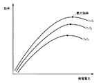
図2は、燃料電池20の温度と、発電効率との関係の一例を示す図である。図2において、横軸は発電電力を示し、縦軸は発電効率を示す。燃料電池20は、化学反応によって電力を生成するため、図2に示すように、燃料電池20の温度(例えばT1〜T3)によって、燃料電池の発電効率は変化する。
【0036】
前述したように、効率格納部50は、それぞれの燃料電池20毎に、図2に示すような発電電力と発電効率との関係を温度毎に格納する。また、効率格納部50が格納した発電効率を更新する場合、制御部60は、選択した補助燃料電池の発電量を順次変化させる。このとき、効率算出部40は、効率格納部50が格納した当該燃料電池20の発電効率の特性のうち、発電効率を算出したときの当該燃料電池20の温度に対応する発電効率を更新する。効率算出部40は、それぞれの燃料電池20の温度を測定する手段を有することが好ましい。
【0037】
また、同様に燃料電池20はその運転圧力によっても発電効率が変動する。ここで、運転圧力とは、例えば燃料電池20に供給される水素、酸素等のガスの圧力である。効率格納部50は、それぞれの燃料電池20の運転圧力毎の発電効率を格納してよい。この場合、制御部60は、それぞれの燃料電池20の運転圧力に更に基づいて、燃料電池20の発電量を制御する。また、効率格納部50が格納した発電効率を更新する場合、効率算出部40は、発電効率を算出したときのそれぞれの燃料電池20の発電効率の特性のうち、発電効率を算出したときの燃料電池の運転圧力に対応する発電効率を更新する。
【0038】
また、それぞれの燃料電池20の発電効率を更新するべき期間として、制御部60は、複数の燃料電池20のうち、累積稼働時間が予め定められた時間になった燃料電池20を、補助燃料電池として選択して、効率算出部40に当該燃料電池20の発電効率を更新させてもよい。この場合、制御部60は、それぞれの燃料電池20の累積稼働時間を計測し、記憶する手段を有することが好ましい。
【0039】
また、それぞれの燃料電池20の発電効率を更新するべき期間として、制御部60は、複数の燃料電池20のうち、累積発電量が予め定められた電力になった燃料電池20を、補助燃料電池として選択して、効率算出部40に当該燃料電池20の発電効率を更新させてもよい。この場合、制御部60は、それぞれの燃料電池20の累積発電量を計測し、記憶する手段を有することが好ましい。
【0040】
また、制御部60は、それぞれの燃料電池20を、予め定められた発電効率の範囲で発電するように制御することが好ましい。例えば、制御部60は、それぞれの燃料電池20を、予め定められた発電効率以上で発電するように制御する。また、制御部60は、補助燃料電池の発電効率を算出する場合に、予め定められた発電量の範囲において補助燃料電池の発電量を順次変化させ、効率算出部40に当該発電量の範囲における補助燃料電池の発電効率を算出させてよい。
【0041】
また、燃料電池20を予め定められた発電効率の範囲で発電させるように制御する場合、それぞれの燃料電池20に対応する二次電池を更に備えることが好ましい。制御部60は、負荷の需要電力のうちの一部又は全部を二次電池から供給させてよい。つまり、負荷の需要電量に応じてそれぞれの燃料電池20を制御した場合に、予め定められた発電効率以下で運転する燃料電池20がある場合、当該燃料電池20を停止させ、当該燃料電池20が発電するべき電力を、対応する二次電池から負荷に供給させる。これにより、燃料電池20を低発電効率で運転させることを防ぐことができる。また、制御部60は、二次電池の蓄電残量が予め定められた残量より少なくなった場合に、燃料電池20に二次電池を充電させることが好ましい。
【0042】
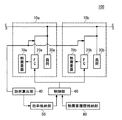
図3は、電力供給システムを備える集合住宅100の構成の他の例を示す。本例における集合住宅100は、図1において説明した集合住宅100の構成に加え、それぞれの住居10に設けられた熱需要器(70a〜70b、以下70と総称する)、及び熱需要履歴格納部80を更に備える。また、それぞれの燃料電池20は、各住居の熱需要器70に対応して設けられ、対応する熱需要器70に排熱を供給する。熱需要器70は、例えば燃料電池20の排熱を温水として貯蔵する貯湯漕である。本例における電力供給システムにおいても、複数の燃料電池20が発電した電力を、各住居の負荷30の需要電力に応じて分配する。
【0043】
制御部60は、それぞれの燃料電池20に、少なくとも対応する熱需要器70の熱需要量に応じた電力を発電させる条件において、複数の燃料電池20の全体の発電効率が最大となるようにそれぞれの燃料電池20の発電量を制御する。
【0044】
例えば、制御部60は、熱需要量の過去の履歴に基づいて、それぞれの熱需要器70に供給するべき熱量の推移を予め算出し、算出した熱量の推移に応じてそれぞれの燃料電池20が最低限発電するべき電力の推移を算出する。そして、それぞれの燃料電池20に、当該最低限の電力を少なくとも発電させる条件で、複数の燃料電池20の全体の発電効率が最大となるようにそれぞれの燃料電池20の発電を制御する。また、熱需要履歴格納部80は、それぞれの熱需要器70の熱需要量の過去の履歴を格納し、制御部60は、熱需要履歴格納部80が格納した熱需要量の履歴を参照することが好ましい。また、制御部60は、対応する熱需要器70の熱需要量が零、又は最も小さくなる燃料電池20を、前述した補助燃料電池として選択してもよい。
【0045】
図4は、電力供給システムを備えた住宅200の構成の一例を示す。住宅200には、電力によって駆動する負荷30が設けられる。また、電力供給システムは、燃料電池20、二次電池90、効率算出部40、効率格納部50、及び制御部60を備える。図4において、図1と同一の符号を付した構成要素は、図1に関連して説明した構成要素と同一又は同様の機能及び構成を有する。
【0046】
二次電池90は、燃料電池20の余剰電力により充電され、燃料電池20の発電電力が不足した場合に、負荷30に不足電力を供給する。例えば、制御部60は、効率格納部50が格納した発電効率に基づいて、燃料電池20の発電効率が最大となるように燃料電池20の発電量を制御する。ここで、発電効率が最大となる場合の燃料電池20の発電量が、負荷30に供給する電力より小さい場合、二次電池90から負荷30に不足電力を供給させる。また、発電効率が最大となる場合の燃料電池20の発電量が、負荷30に供給する電力より大きい場合、余剰の電力を二次電池90に充電する。このような動作により、燃料電池20を効率よく発電させることができる。
【0047】
また、制御部60は、負荷30に供給するべき電力が予め定められた電力より小さく、且つ二次電池90の蓄電量が予め定められた蓄電量より大きい場合、燃料電池を停止させ、二次電池90から負荷30に電力を供給させてもよい。この場合、予め定められた電力とは、効率格納部50が格納した発電効率が所定の効率となる電力であってよい。このような動作により、燃料電池を更に効率よく発電させることができる。
【0048】
また、制御部60は、予め定められた期間毎に、燃料電池20の発電効率を測定するべく、燃料電池20の発電量を順次変化させる。効率算出部40は、燃料電池の発電量毎の発電効率を算出し、効率格納部50に格納する。燃料電池20の発電効率を測定するときには、制御部60は、不足電力を二次電池90から負荷30に供給させる。このような動作により、負荷30に安定して電力を供給しつつ、燃料電池20の発電効率を更新することができる。
【0049】
図5は、電力供給システムを制御するコンピュータ300の構成の一例を示す。本例において、コンピュータ300は、電力供給システムを図1、図3又は図4において説明した電力供給システムとして機能させるプログラムを格納する。また、コンピュータ300は、電力供給システムの制御部60、効率算出部40、及び効率格納部50として更に機能してもよい。
【0050】
コンピュータ300は、CPU700と、ROM702と、RAM704と、通信インターフェース706と、ハードディスクドライブ710と、フレキシブルディスクドライブ712と、CD−ROMドライブ714とを備える。CPU700は、ROM702、RAM704、ハードディスクドライブ710、フレキシブルディスク720、及び/又はCD−ROM722に格納されたプログラムに基づいて動作する。
【0051】
例えば、コンピュータ300を電力供給システムとして機能させるプログラムは、コンピュータ300を、図1及び図3に関連して説明した熱需要履歴格納部80、制御部60、効率算出部40、及び効率格納部50として機能させ、燃料電池20を図1に関連して説明したように制御させ、電力供給システムを機能させる。また、コンピュータ300を電力供給システムとして機能させるプログラムは、コンピュータ300を、図4に関連して説明した制御部60、効率算出部40、及び効率格納部50として機能させ、燃料電池20及び二次電池90を図4に関連して説明したように制御させ、電力供給システムを機能させる。
【0052】
通信インターフェース706は、例えば燃料電池20、二次電池90と通信し、それぞれの状態等に関する情報を受信し、またそれぞれを制御する制御信号を送信する。格納装置の一例としてのハードディスクドライブ710、ROM702、又はRAM704は、設定情報、及びCPU700を動作させるためのプログラム等を格納する。また、当該プログラムは、フレキシブルディスク720、CD−ROM722等の記録媒体に格納されていてもよい。
【0053】
フレキシブルディスクドライブ712は、フレキシブルディスク720がプログラムを格納している場合、フレキシブルディスク720からプログラムを読み取りCPU700に提供する。CD−ROMドライブ714は、CD−ROM722がプログラムを格納している場合、CD−ROM722からプログラムを読み取りCPU700に提供する。
【0054】
また、プログラムは記録媒体から直接RAMに読み出されて実行されても、一旦ハードディスクドライブにインストールされた後にRAMに読み出されて実行されてもよい。更に、上記プログラムは単一の記録媒体に格納されても複数の記録媒体に格納されても良い。また記録媒体に格納されるプログラムは、オペレーティングシステムとの共同によってそれぞれの機能を提供してもよい。例えば、プログラムは、機能の一部または全部を行うことをオペレーティングシステムに依頼し、オペレーティングシステムからの応答に基づいて機能を提供するものであってもよい。
【0055】
プログラムを格納する記録媒体としては、フレキシブルディスク、CD−ROMの他にも、DVD、PD等の光学記録媒体、MD等の光磁気記録媒体、テープ媒体、磁気記録媒体、ICカードやミニチュアーカードなどの半導体メモリー等を用いることができる。又、専用通信ネットワークやインターネットに接続されたサーバシステムに設けたハードディスクまたはRAM等の格納装置を記録媒体として使用してもよい。
【0056】
以上、本発明を実施の形態を用いて説明したが、本発明の技術的範囲は上記実施の形態に記載の範囲には限定されない。上記実施の形態に、多様な変更又は改良を加えることが可能であることが当業者に明らかである。その様な変更又は改良を加えた形態も本発明の技術的範囲に含まれ得ることが、特許請求の範囲の記載から明らかである。
【0057】
【発明の効果】
以上の説明から明らかなように、本発明によれば、定期的に燃料電池の発電効率を測定することにより、燃料電池が経時的に劣化した場合であっても、燃料電池を高効率の領域で運転することができる。
【図面の簡単な説明】
【図1】本発明の実施形態に係る電力供給システムを備えた集合住宅100の一例を示す図である。
【図2】燃料電池の温度毎の、発電電力と発電効率との関係の一例を示す図である。
【図3】集合住宅100の構成の他の例を示す図である。
【図4】本発明の実施形態に係る電力供給システムを備えた住宅200の構成の一例を示す図である。
【図5】電力供給システムを制御するコンピュータ300の構成の一例を示す図である。
【符号の説明】
10・・・住居、20・・・燃料電池、30・・・負荷、40・・・効率算出部、50・・・効率格納部、60・・・制御部、70・・・熱需要器、80・・・熱需要履歴格納部、90・・・二次電池、100・・・集合住宅、200・・・住宅、300・・・コンピュータ、700・・・CPU、702・・・ROM、704・・・RAM、706・・・通信インターフェース、710・・・ハードディスクドライブ、712・・・フレキシブルディスクドライブ、714・・・CD−ROMドライブ、720・・・フレキシブルディスク、722・・・CD−ROM[0001]
BACKGROUND OF THE INVENTION
The present invention relates to a power supply system that supplies power to a load, a housing complex that includes the power supply system, and a program that causes the power supply system to function. In particular, the present invention relates to a power supply system having a fuel cell.
[0002]
[Prior art]
Conventionally, solar power generation, fuel cells, etc. in each house have been considered as auxiliary power sources for electric power systems. In addition, due to the recent increase in power demand, it is expected that power supply from the power system will be short in the near future. For this reason, in the electric power supply of each house, it is thought that the dependence with respect to solar power generation, a fuel cell, etc. increases. That is, it is expected that a fuel cell or the like conventionally used as an auxiliary power source functions as a main power source for each house. Further, the power generation efficiency of the fuel cell varies depending on the generated power. For this reason, the fuel cell is preferably controlled so that its power generation efficiency is as large as possible.
[0003]
For example, in a power plant equipped with a plurality of fuel cells, in order to improve the power generation efficiency of the entire fuel cell, the number of fuel cells to be operated is set according to the power load, and each fuel cell is loaded with a high power generation efficiency. There is a system that drives at a rate. In this case, the power generation efficiency characteristic of the fuel cell with respect to the load factor is given in advance, and the power generation of the fuel cell is controlled based on the given power generation efficiency characteristic.
The following documents have been discovered as conventional techniques.
[Patent Document 1]
JP 2002-171671 A
[Patent Document 2]
Japanese Patent Laid-Open No. 08-236128
[Patent Document 3]
Japanese Patent Laid-Open No. 2003-075507
[0004]
[Problems to be solved by the invention]
However, since the characteristics of the fuel cell deteriorate with time, the characteristics of power generation efficiency also vary with time. For example, in a solid electrolyte fuel cell, when the electrolyte membrane is operated in an excessively humidified or insufficiently humidified state, the power generation efficiency of the fuel cell is greatly degraded.
[0005]
However, the conventional system does not take into account this change over time, and thus it may be difficult to operate the fuel cell with high efficiency. For example, even when each fuel cell is intended to be operated at maximum efficiency, the power generation efficiency characteristics of the fuel cell fluctuate over time from the characteristics measured in advance, and the generated power that achieves the maximum efficiency fluctuates. Therefore, it cannot be operated at maximum efficiency. Further, since the characteristics of the fuel cell vary depending on the operating environment such as the temperature of the fuel cell, it is difficult to operate the fuel cell with high efficiency by the conventional control method.
[0006]
[Means for Solving the Problems]
In order to solve the above problems, in the first embodiment of the present invention, there is provided a power supply system for supplying power to a load, wherein the fuel cell generates power and supplies the load to the load, and for each generated power of the fuel cell. An efficiency storage unit that stores power generation efficiency, an efficiency calculation unit that calculates the power generation efficiency of the fuel cell for each predetermined period, and updates the power generation efficiency stored in the efficiency storage unit, and the power generation stored in the efficiency storage unit Provided is a power supply system including a control unit that controls power generation of a fuel cell based on efficiency.
[0007]
The battery further includes a secondary battery that is charged with surplus power of the fuel cell, and the control unit controls the power generation amount of the fuel cell so that the power generation efficiency of the fuel cell is maximized, and the power generation amount of the fuel cell is supplied to the load. When the power is smaller than the power, the secondary battery is supplied with insufficient power, and when the amount of power generated by the fuel cell is larger than the power supplied to the load, the secondary battery may be charged with surplus power.
[0008]
When the power to be supplied to the load is smaller than the predetermined power and the storage amount of the secondary battery is larger than the predetermined storage amount, the control unit stops the fuel cell and supplies power from the secondary battery to the load. May be supplied.
[0009]
In the second aspect of the present invention, a power supply system for supplying power to a load, which includes a plurality of fuel cells that generate power and supply the load to the load, a control unit that controls power generation of the fuel cell, and generated power The efficiency storage unit that stores the power generation efficiency for each fuel cell, and the power generation efficiency for each power generation power of each fuel cell calculated for each predetermined period and stored in the efficiency storage unit And an efficiency calculation unit that updates the power generation amount of each fuel cell based on the power generation efficiency stored in the efficiency storage unit so that the overall power generation efficiency of the plurality of fuel cells is maximized. Provided is a power supply system that generates electric power to be controlled and supplied to a load.
[0010]
The control unit sequentially selects at least one auxiliary fuel cell to generate power as an auxiliary from a plurality of fuel cells every predetermined period, and the efficiency calculation unit calculates the power generation efficiency of the auxiliary fuel cell. It's okay.
[0011]
The control unit sequentially changes the power generation amount of the auxiliary fuel cell to cause the efficiency calculation unit to calculate the power generation efficiency, and among the plurality of fuel cells, the power to be supplied to the load and the auxiliary fuel to fuel cells other than the auxiliary fuel cell You may generate the electric power of the difference with the electric power generation amount of a battery.
[0012]
The efficiency calculation unit is given in advance deterioration information indicating the magnitude of deterioration of the power generation efficiency with respect to the cumulative operation time of the fuel cell, and calculates the power generation efficiency of each fuel cell based on the cumulative operation time of each fuel cell. It's okay.
[0013]
The efficiency calculation unit is given in advance deterioration information indicating the degree of deterioration in power generation efficiency relative to the cumulative power generation amount of the fuel cell, and calculates the power generation efficiency of each fuel cell based on the cumulative power generation amount of each fuel cell. It's okay.
[0014]
The efficiency storage unit may store the power generation efficiency for each temperature of each fuel cell, and the control unit may further control the power generation amount of the fuel cell based on the temperature of each fuel cell. The efficiency storage unit stores the power generation efficiency for each temperature of each fuel cell, the control unit sequentially changes the power generation amount of the auxiliary fuel cell to cause the efficiency calculation unit to calculate the power generation efficiency, Of the power generation efficiency of the auxiliary fuel cell stored in the efficiency storage unit, the power generation efficiency corresponding to the temperature of the auxiliary fuel cell when the power generation efficiency is calculated may be updated.
[0015]
The efficiency storage unit may store the power generation efficiency for each operating pressure of each fuel cell, and the control unit may control the power generation amount of the fuel cell based further on the operating pressure of each fuel cell. The efficiency storage unit stores the power generation efficiency for each operating pressure of each fuel cell, the control unit sequentially changes the power generation amount of the auxiliary fuel cell, causes the efficiency calculation unit to calculate the power generation efficiency, and the efficiency calculation unit Of the power generation efficiency of the auxiliary fuel cell stored in the efficiency storage unit, the power generation efficiency corresponding to the operating pressure of the auxiliary fuel cell when the power generation efficiency is calculated may be updated.
[0016]
The control unit may select, as an auxiliary fuel cell, a fuel cell having a predetermined operating time among the plurality of fuel cells. Further, the control unit may select a fuel cell in which the total power generation amount is a predetermined power among the plurality of fuel cells as the auxiliary fuel cell.
[0017]
The plurality of fuel cells are provided corresponding to heat demanders that should supply exhaust heat, the power supply system distributes the electric power generated by the plurality of fuel cells to the load of each house, and the control unit controls each fuel. The power generation amount of each fuel cell may be controlled so that the overall power generation efficiency of the plurality of fuel cells is maximized on the condition that the battery generates power corresponding to at least the heat demand of the corresponding heat demander. .
[0018]
In the 3rd form of this invention, it is an apartment house provided with a some residence, Comprising: The some fuel cell provided for each residence, The control part which controls the electric power generation of a some fuel cell, Generated power The power generation efficiency for each fuel cell is stored for each fuel cell, and the power generation efficiency of each fuel cell stored by the efficiency storage unit is calculated for each predetermined period, and the efficiency storage unit stores the power generation efficiency. An efficiency calculation unit that updates the power generation efficiency, and the control unit generates power from each fuel cell so that the overall power generation efficiency of the plurality of fuel cells is maximized based on the power generation efficiency stored in the efficiency storage unit. An apartment house that generates electric power to be supplied to a load by controlling the amount is provided.
[0019]
The apartment house further includes a power distribution unit that distributes the power generated by the plurality of fuel cells to the load of each house, and the fuel cell has means for supplying exhaust heat to the heat demander of the corresponding residence, and the control unit is The power generation amount of each fuel cell is set so that the overall power generation efficiency of the plurality of fuel cells is maximized under the condition that each fuel cell generates power according to the heat demand of the corresponding heat demander. You may control.
[0020]
According to a fourth aspect of the present invention, there is provided a program for causing a power supply system to function, the power supply system including a plurality of fuel cells that generate power and supply the load to a load, and a control unit that controls power generation of the fuel cell; An efficiency storage unit that stores the power generation efficiency of each generated power for each fuel cell, and the power generation efficiency of each fuel cell stored in the efficiency storage unit is calculated for each predetermined period, and the efficiency storage unit And an efficiency calculation unit that updates the power generation efficiency stored in the fuel cell, and the control unit controls each fuel so that the total power generation efficiency of the plurality of fuel cells is maximized based on the power generation efficiency stored in the efficiency storage unit. A program for controlling a power generation amount of a battery to function as a power supply system that generates power to be supplied to a load is provided.
[0021]
The above summary of the invention does not enumerate all the necessary features of the present invention, and sub-combinations of these feature groups can also be the invention.
[0022]
DETAILED DESCRIPTION OF THE INVENTION
Hereinafter, the present invention will be described through embodiments of the invention. However, the following embodiments do not limit the invention according to the claims, and all combinations of features described in the embodiments are included. It is not necessarily essential for the solution of the invention.
[0023]
FIG. 1 shows an example of an
[0024]
The power supply system includes a plurality of fuel cells (20 a to 20 c), an
[0025]
The
[0026]
The
[0027]
The
[0028]
According to the power supply system in this example, the power generation efficiency for each generated power of each
[0029]
In addition, in order to periodically measure the power generation efficiency of each
[0030]
In addition, the
[0031]
Further, as another example of calculating the variation with time of the power generation efficiency of each
[0032]
Further, as yet another example of calculating the temporal variation of the power generation efficiency of each
[0033]
Further, the
[0034]
Further, the
[0035]
FIG. 2 is a diagram illustrating an example of the relationship between the temperature of the
[0036]
As described above, the
[0037]
Similarly, the power generation efficiency of the
[0038]
In addition, as a period during which the power generation efficiency of each
[0039]
In addition, as a period in which the power generation efficiency of each
[0040]
Moreover, it is preferable that the
[0041]
In addition, when controlling the
[0042]
FIG. 3 shows another example of the configuration of the
[0043]
The
[0044]
For example, the
[0045]
FIG. 4 shows an example of the configuration of a
[0046]
The
[0047]
Further, the
[0048]
In addition, the
[0049]
FIG. 5 shows an example of the configuration of a
[0050]
The
[0051]
For example, a program that causes the
[0052]
The
[0053]
When the
[0054]
In addition, the program may be read from the recording medium directly into the RAM and executed, or once installed in the hard disk drive, the program may be read into the RAM and executed. Further, the program may be stored in a single recording medium or a plurality of recording media. The program stored in the recording medium may provide each function in cooperation with the operating system. For example, the program may request the operating system to perform a part or all of the function and provide the function based on a response from the operating system.
[0055]
As a recording medium for storing a program, in addition to a flexible disk and a CD-ROM, an optical recording medium such as a DVD and a PD, a magneto-optical recording medium such as an MD, a tape medium, a magnetic recording medium, an IC card, a miniature card, etc. A semiconductor memory or the like can be used. A storage device such as a hard disk or a RAM provided in a server system connected to a dedicated communication network or the Internet may be used as a recording medium.
[0056]
As mentioned above, although this invention was demonstrated using embodiment, the technical scope of this invention is not limited to the range as described in the said embodiment. It will be apparent to those skilled in the art that various modifications or improvements can be added to the above embodiment. It is apparent from the scope of the claims that the embodiments added with such changes or improvements can be included in the technical scope of the present invention.
[0057]
【The invention's effect】
As is clear from the above description, according to the present invention, by periodically measuring the power generation efficiency of the fuel cell, even if the fuel cell deteriorates over time, the fuel cell can be You can drive at.
[Brief description of the drawings]
FIG. 1 is a diagram illustrating an example of an
FIG. 2 is a diagram showing an example of the relationship between generated power and power generation efficiency for each temperature of the fuel cell.
FIG. 3 is a diagram illustrating another example of the configuration of the
FIG. 4 is a diagram illustrating an example of a configuration of a
FIG. 5 is a diagram illustrating an example of a configuration of a
[Explanation of symbols]
DESCRIPTION OF SYMBOLS 10 ... Residence, 20 ... Fuel cell, 30 ... Load, 40 ... Efficiency calculation part, 50 ... Efficiency storage part, 60 ... Control part, 70 ... Heat demand device, 80 ... heat demand history storage unit, 90 ... secondary battery, 100 ... collective housing, 200 ... housing, 300 ... computer, 700 ... CPU, 702 ... ROM, 704 ... RAM, 706 ... communication interface, 710 ... hard disk drive, 712 ... flexible disk drive, 714 ... CD-ROM drive, 720 ... flexible disk, 722 ... CD-ROM
Claims (26)
電力を発電し前記負荷に供給する複数の燃料電池と、
前記燃料電池の発電を制御する制御部と、
それぞれの前記燃料電池の、発電電力毎でかつ温度毎の発電効率を格納する効率格納部と、
を備え、
前記制御部は、それぞれの前記燃料電池の温度に更に基づいて、前記効率格納部が格納した前記発電効率を用いて、前記複数の燃料電池の全体の発電効率が最大となるように、それぞれの前記燃料電池の発電量を制御して前記負荷に供給するべき電力を発電させる電力供給システム。A power supply system for supplying power to a load,
A plurality of fuel cells that generate electric power and supply the load to the load;
A control unit for controlling power generation of the fuel cell;
An efficiency storage section for storing the power generation efficiency for each generated power and for each temperature of each fuel cell;
With
The control unit further uses the power generation efficiency stored in the efficiency storage unit based on the temperature of each fuel cell so that the overall power generation efficiency of the plurality of fuel cells is maximized. An electric power supply system for generating electric power to be supplied to the load by controlling an electric power generation amount of the fuel cell.
前記効率算出部は、前記補助燃料電池の前記発電効率を算出する請求項2に記載の電力供給システム。 The power supply system according to claim 2, wherein the efficiency calculation unit calculates the power generation efficiency of the auxiliary fuel cell.
請求項3に記載の電力供給システム。 The power supply system according to claim 3.
電力を発電し前記負荷に供給する複数の燃料電池と、
前記燃料電池の発電を制御する制御部と、
それぞれの前記燃料電池の、発電電力毎でかつ運転圧力毎の発電効率を格納する効率格納部と、
それぞれの前記燃料電池の前記発電電力毎の発電効率を算出し、前記効率格納部が格納した前記発電効率を更新する効率算出部と
を備え、
前記制御部は、前記効率格納部が格納した前記発電効率を用いて、それぞれの前記燃料電池の運転圧力に更に基づいて、前記複数の燃料電池の全体の発電効率が最大となるように、それぞれの前記燃料電池の発電量を制御して前記負荷に供給するべき電力を発電させる
電力供給システム。A power supply system for supplying power to a load,
A plurality of fuel cells that generate electric power and supply the load to the load;
A control unit for controlling power generation of the fuel cell;
An efficiency storage for storing the power generation efficiency of each fuel cell for each generated power and for each operating pressure;
A power generation efficiency for each of the generated power of each of the fuel cells is calculated, and an efficiency calculation unit that updates the power generation efficiency stored in the efficiency storage unit, and
The control unit uses the power generation efficiency stored in the efficiency storage unit to further maximize the power generation efficiency of the plurality of fuel cells based on the operating pressure of each of the fuel cells. A power supply system for controlling the power generation amount of the fuel cell to generate power to be supplied to the load.
前記効率算出部は、前記補助燃料電池の前記発電効率を算出する請求項10に記載の電力供給システム。 The power supply system according to claim 10, wherein the efficiency calculation unit calculates the power generation efficiency of the auxiliary fuel cell.
前記複数の燃料電池の発電を制御する制御部と、
発電電力毎の発電効率を、それぞれの前記燃料電池毎に格納する効率格納部と、
前記効率格納部が格納したそれぞれの前記燃料電池の前記発電効率を算出し、前記効率格納部が格納した前記発電効率を更新する効率算出部と、
前記複数の燃料電池が発電した電力を負荷に分配する配電部と
を備え、
前記制御部は、
少なくとも対応する前記熱需要器の熱需要量に応じた電力を発電させる条件において、前記効率格納部が格納した前記発電効率に基づいて、前記複数の燃料電池の全体の発電効率が最大となるように、それぞれの前記燃料電池の発電量を制御して前記負荷に供給するべき電力を発電させる
電力供給システム。A plurality of fuel cells having means for supplying waste heat to the heat consumer;
A control unit for controlling power generation of the plurality of fuel cells;
An efficiency storage unit for storing the power generation efficiency for each generated power for each of the fuel cells;
An efficiency calculation unit that calculates the power generation efficiency of each of the fuel cells stored in the efficiency storage unit and updates the power generation efficiency stored in the efficiency storage unit;
A power distribution unit that distributes the power generated by the plurality of fuel cells to a load;
The controller is
Based on the power generation efficiency stored in the efficiency storage unit, the power generation efficiency of the plurality of fuel cells as a whole is maximized on the condition that power is generated according to the heat demand of the corresponding heat demander. And a power supply system that generates power to be supplied to the load by controlling the power generation amount of each of the fuel cells.
前記効率算出部は、前記補助燃料電池の前記発電効率を算出する請求項18に記載の電力供給システム。 The power supply system according to claim 18, wherein the efficiency calculation unit calculates the power generation efficiency of the auxiliary fuel cell.
排熱を供給するべき熱需要器に対応して設けられ、電力を発電して前記負荷に供給する複数の燃料電池と、
前記燃料電池の発電を制御する制御部と、
発電電力毎の発電効率を、それぞれの前記燃料電池毎に格納する効率格納部と、
それぞれの前記燃料電池の前記発電電力毎の発電効率を算出し、前記効率格納部が格納した前記発電効率を更新する効率算出部と
を備え、
前記制御部は、前記効率格納部が格納した前記発電効率に基づいて、前記複数の燃料電池の全体の発電効率が最大となるように、それぞれの前記燃料電池の発電量を制御して前記負荷に供給するべき電力を発電させ、
前記電力供給システムは、前記複数の燃料電池が発電した電力を各戸の前記負荷に分配し、
前記制御部は、それぞれの前記燃料電池に、少なくとも対応する前記熱需要器の熱需要量に応じた電力を発電させる条件において、前記複数の燃料電池の全体の発電効率が最大となるようにそれぞれの前記燃料電池の発電量を制御する電力供給システム。A power supply system for supplying power to a load,
A plurality of fuel cells provided corresponding to a heat demander to supply waste heat, and generating electric power and supplying the load to the load;
A control unit for controlling power generation of the fuel cell;
An efficiency storage unit for storing the power generation efficiency for each generated power for each of the fuel cells;
A power generation efficiency for each of the generated power of each of the fuel cells is calculated, and an efficiency calculation unit that updates the power generation efficiency stored in the efficiency storage unit, and
The control unit controls the power generation amount of each of the fuel cells based on the power generation efficiency stored in the efficiency storage unit so that the overall power generation efficiency of the plurality of fuel cells is maximized. To generate electricity to be supplied to
The power supply system distributes the power generated by the plurality of fuel cells to the load of each house,
The control unit is configured so that the power generation efficiency of the plurality of fuel cells is maximized on the condition that each of the fuel cells generates power according to the amount of heat demand of the corresponding heat demander. A power supply system for controlling the power generation amount of the fuel cell.
それぞれの前記住居毎に設けられた複数の燃料電池と、
前記複数の燃料電池の発電を制御する制御部と、
発電電力毎の発電効率を、それぞれの前記燃料電池毎に格納する効率格納部と、
前記効率格納部が格納したそれぞれの前記燃料電池の前記発電効率を算出し、前記効率格納部が格納した前記発電効率を更新する効率算出部と、
前記複数の燃料電池が発電した電力を各戸の前記負荷に分配する配電部と
を備え、
前記燃料電池は、対応する前記住居の熱需要器に排熱を供給する手段を有し、
前記制御部は、
少なくとも対応する前記熱需要器の熱需要量に応じた電力を発電させる条件において、前記効率格納部が格納した前記発電効率に基づいて、前記複数の燃料電池の全体の発電効率が最大となるように、それぞれの前記燃料電池の発電量を制御して前記負荷に供給するべき電力を発電させる
集合住宅。An apartment house with multiple residences,
A plurality of fuel cells provided for each of the residences;
A control unit for controlling power generation of the plurality of fuel cells;
An efficiency storage unit for storing the power generation efficiency for each generated power for each of the fuel cells;
An efficiency calculation unit that calculates the power generation efficiency of each of the fuel cells stored in the efficiency storage unit and updates the power generation efficiency stored in the efficiency storage unit;
A power distribution unit that distributes the power generated by the plurality of fuel cells to the load of each door;
The fuel cell has means for supplying exhaust heat to the corresponding heat demander of the residence,
The controller is
Based on the power generation efficiency stored in the efficiency storage unit, the power generation efficiency of the plurality of fuel cells as a whole is maximized on the condition that power is generated according to the heat demand of the corresponding heat demander. In addition, the apartment house controls the amount of power generated by each of the fuel cells to generate power to be supplied to the load.
Priority Applications (2)
| Application Number | Priority Date | Filing Date | Title |
|---|---|---|---|
| JP2003116978A JP3609397B2 (en) | 2003-04-22 | 2003-04-22 | Power supply system, housing complex, and program |
| JP2004180283A JP4718133B2 (en) | 2003-04-22 | 2004-06-17 | Power supply system, housing complex, and program |
Applications Claiming Priority (2)
| Application Number | Priority Date | Filing Date | Title |
|---|---|---|---|
| JP2003116978A JP3609397B2 (en) | 2003-04-22 | 2003-04-22 | Power supply system, housing complex, and program |
| JP2004180283A JP4718133B2 (en) | 2003-04-22 | 2004-06-17 | Power supply system, housing complex, and program |
Related Child Applications (1)
| Application Number | Title | Priority Date | Filing Date |
|---|---|---|---|
| JP2004180283A Division JP4718133B2 (en) | 2003-04-22 | 2004-06-17 | Power supply system, housing complex, and program |
Publications (2)
| Publication Number | Publication Date |
|---|---|
| JP2004327120A JP2004327120A (en) | 2004-11-18 |
| JP3609397B2 true JP3609397B2 (en) | 2005-01-12 |
Family
ID=55085419
Family Applications (2)
| Application Number | Title | Priority Date | Filing Date |
|---|---|---|---|
| JP2003116978A Expired - Fee Related JP3609397B2 (en) | 2003-04-22 | 2003-04-22 | Power supply system, housing complex, and program |
| JP2004180283A Expired - Fee Related JP4718133B2 (en) | 2003-04-22 | 2004-06-17 | Power supply system, housing complex, and program |
Family Applications After (1)
| Application Number | Title | Priority Date | Filing Date |
|---|---|---|---|
| JP2004180283A Expired - Fee Related JP4718133B2 (en) | 2003-04-22 | 2004-06-17 | Power supply system, housing complex, and program |
Country Status (1)
| Country | Link |
|---|---|
| JP (2) | JP3609397B2 (en) |
Families Citing this family (15)
| Publication number | Priority date | Publication date | Assignee | Title |
|---|---|---|---|---|
| JP4749088B2 (en) * | 2005-08-26 | 2011-08-17 | 三洋電機株式会社 | Operation method of fuel cell power generator |
| JP5295694B2 (en) * | 2008-09-11 | 2013-09-18 | 東芝燃料電池システム株式会社 | Fuel cell system and operation method thereof |
| JP5972526B2 (en) * | 2010-08-04 | 2016-08-17 | 学校法人幾徳学園 | Fuel cell power generation control device, fuel cell power generation system, fuel cell power generation control method, and program |
| JP6125750B2 (en) * | 2011-12-28 | 2017-05-10 | 学校法人幾徳学園 | Fuel cell power generation system and control method thereof |
| JP6452330B2 (en) * | 2014-07-10 | 2019-01-16 | 京セラ株式会社 | Power generation device, power generation system, and power generation method |
| US10523015B2 (en) | 2014-07-10 | 2019-12-31 | Kyocera Corporation | Power generation apparatus, power generation system, and power generation method |
| JP2016019428A (en) * | 2014-07-10 | 2016-02-01 | 京セラ株式会社 | Power generation device, power generation system, and power generation method |
| US10879548B2 (en) | 2016-01-28 | 2020-12-29 | Kyocera Corporation | Power generation system, method for controlling power generation system, and power generation apparatus |
| JP2019196775A (en) * | 2016-09-16 | 2019-11-14 | ライフロボティクス株式会社 | Linear motion expansion mechanism and robot arm mechanism including the same |
| JP7402122B2 (en) * | 2020-06-04 | 2023-12-20 | 本田技研工業株式会社 | Power supply control system, power supply control method, and program |
| JP7567397B2 (en) | 2020-11-25 | 2024-10-16 | スズキ株式会社 | Fuel cell system and fuel cell power generation system |
| JP7630335B2 (en) * | 2021-03-30 | 2025-02-17 | 大阪瓦斯株式会社 | Power Management System |
| JP2023050950A (en) * | 2021-09-30 | 2023-04-11 | 株式会社小松製作所 | WORKING MACHINE CONTROL DEVICE AND WORKING MACHINE CONTROL METHOD |
| KR102770722B1 (en) * | 2022-03-02 | 2025-02-21 | 주식회사 빈센 | Method and system for sequentially controlling fuel cell |
| JP2024115244A (en) * | 2023-02-14 | 2024-08-26 | いすゞ自動車株式会社 | Operation control device and power supply system |
Family Cites Families (3)
| Publication number | Priority date | Publication date | Assignee | Title |
|---|---|---|---|---|
| JP2877653B2 (en) * | 1993-03-24 | 1999-03-31 | 三洋電機株式会社 | Operating method of phosphoric acid fuel cell |
| JP3145599B2 (en) * | 1995-02-27 | 2001-03-12 | 京セラ株式会社 | Solid oxide fuel cell |
| JP2002171671A (en) * | 2000-12-04 | 2002-06-14 | Mitsubishi Electric Corp | Instantaneous interruption independent transition power generation system |
-
2003
- 2003-04-22 JP JP2003116978A patent/JP3609397B2/en not_active Expired - Fee Related
-
2004
- 2004-06-17 JP JP2004180283A patent/JP4718133B2/en not_active Expired - Fee Related
Also Published As
| Publication number | Publication date |
|---|---|
| JP2004327448A (en) | 2004-11-18 |
| JP2004327120A (en) | 2004-11-18 |
| JP4718133B2 (en) | 2011-07-06 |
Similar Documents
| Publication | Publication Date | Title |
|---|---|---|
| JP3609397B2 (en) | Power supply system, housing complex, and program | |
| JP7162284B2 (en) | Hydrogen supply system | |
| Qiu et al. | A field validated model of a vanadium redox flow battery for microgrids | |
| US8364287B2 (en) | Apparatus, system, and method to manage the generation and use of hybrid electric power | |
| JP5841817B2 (en) | Power feeding system and method for controlling power feeding system | |
| Tanrioven | Reliability and cost–benefits of adding alternate power sources to an independent micro-grid community | |
| JP2008539683A (en) | Systems and Methods for Adaptive Energy Management in a Fuel Cell System The section headings used herein are for structural use and therefore should not be construed as limiting the claims in any way. | |
| CN103703648A (en) | Power management system and management method | |
| KR102503382B1 (en) | Method for power management of Energy Storage System connected renewable energy | |
| US11909213B1 (en) | Energy storage system and method of operation thereof | |
| CA2763056A1 (en) | Integrated fuel processor and fuel cell system control method | |
| US11922523B2 (en) | Information processing device, information processing system, and program for acquiring power generation information and generating proposal information including a type of electric power to be selected | |
| JP4202371B2 (en) | Power supply system, housing complex, and program | |
| Pregelj et al. | Impact of fuel cell and battery size to overall system performance–A diesel fuel-cell APU case study | |
| US20050255353A1 (en) | Fuel-cell power system | |
| JP2011243447A (en) | Fuel cell control system | |
| JP3814593B2 (en) | Electric heat supply system, housing complex, and program | |
| JP4808939B2 (en) | FUEL CELL SYSTEM, FUEL CELL SYSTEM CONTROL METHOD, AND MULTIPLE HOUSING FOR IMPROVING ENERGY EFFICIENCY OF THE SYSTEM | |
| Pregelj et al. | Improving the operation of a fuel-cell power unit with supervision control–A simulation study | |
| CN117195716A (en) | An electricity and hydrogen federation planning method and system | |
| CN116094062A (en) | Management method, device, equipment and storage medium of fuel cell micro-grid | |
| Raceanu et al. | Design and Experimental Investigations of an Energy Storage System in Microgrids | |
| Ondrejička et al. | Fuel cells as backup power supply for production processes | |
| Sayah et al. | Performance evaluation of neural network models for fuel cell power prediction in hybrid electric vehicles | |
| JP2022170164A (en) | Energy management system |
Legal Events
| Date | Code | Title | Description |
|---|---|---|---|
| A521 | Request for written amendment filed |
Free format text: JAPANESE INTERMEDIATE CODE: A523 Effective date: 20040909 |
|
| TRDD | Decision of grant or rejection written | ||
| A01 | Written decision to grant a patent or to grant a registration (utility model) |
Free format text: JAPANESE INTERMEDIATE CODE: A01 Effective date: 20041012 |
|
| A61 | First payment of annual fees (during grant procedure) |
Free format text: JAPANESE INTERMEDIATE CODE: A61 Effective date: 20041013 |
|
| R150 | Certificate of patent or registration of utility model |
Ref document number: 3609397 Country of ref document: JP Free format text: JAPANESE INTERMEDIATE CODE: R150 Free format text: JAPANESE INTERMEDIATE CODE: R150 |
|
| FPAY | Renewal fee payment (event date is renewal date of database) |
Free format text: PAYMENT UNTIL: 20081022 Year of fee payment: 4 |
|
| R250 | Receipt of annual fees |
Free format text: JAPANESE INTERMEDIATE CODE: R250 |
|
| FPAY | Renewal fee payment (event date is renewal date of database) |
Free format text: PAYMENT UNTIL: 20081022 Year of fee payment: 4 |
|
| FPAY | Renewal fee payment (event date is renewal date of database) |
Free format text: PAYMENT UNTIL: 20091022 Year of fee payment: 5 |
|
| R250 | Receipt of annual fees |
Free format text: JAPANESE INTERMEDIATE CODE: R250 |
|
| FPAY | Renewal fee payment (event date is renewal date of database) |
Free format text: PAYMENT UNTIL: 20101022 Year of fee payment: 6 |
|
| R250 | Receipt of annual fees |
Free format text: JAPANESE INTERMEDIATE CODE: R250 |
|
| FPAY | Renewal fee payment (event date is renewal date of database) |
Free format text: PAYMENT UNTIL: 20101022 Year of fee payment: 6 |
|
| FPAY | Renewal fee payment (event date is renewal date of database) |
Free format text: PAYMENT UNTIL: 20111022 Year of fee payment: 7 |
|
| R250 | Receipt of annual fees |
Free format text: JAPANESE INTERMEDIATE CODE: R250 |
|
| FPAY | Renewal fee payment (event date is renewal date of database) |
Free format text: PAYMENT UNTIL: 20121022 Year of fee payment: 8 |
|
| R250 | Receipt of annual fees |
Free format text: JAPANESE INTERMEDIATE CODE: R250 |
|
| FPAY | Renewal fee payment (event date is renewal date of database) |
Free format text: PAYMENT UNTIL: 20121022 Year of fee payment: 8 |
|
| FPAY | Renewal fee payment (event date is renewal date of database) |
Free format text: PAYMENT UNTIL: 20131022 Year of fee payment: 9 |
|
| R250 | Receipt of annual fees |
Free format text: JAPANESE INTERMEDIATE CODE: R250 |
|
| R250 | Receipt of annual fees |
Free format text: JAPANESE INTERMEDIATE CODE: R250 |
|
| S531 | Written request for registration of change of domicile |
Free format text: JAPANESE INTERMEDIATE CODE: R313531 |
|
| S802 | Written request for registration of partial abandonment of right |
Free format text: JAPANESE INTERMEDIATE CODE: R311802 |
|
| R350 | Written notification of registration of transfer |
Free format text: JAPANESE INTERMEDIATE CODE: R350 |
|
| R250 | Receipt of annual fees |
Free format text: JAPANESE INTERMEDIATE CODE: R250 |
|
| R250 | Receipt of annual fees |
Free format text: JAPANESE INTERMEDIATE CODE: R250 |
|
| R250 | Receipt of annual fees |
Free format text: JAPANESE INTERMEDIATE CODE: R250 |
|
| R250 | Receipt of annual fees |
Free format text: JAPANESE INTERMEDIATE CODE: R250 |
|
| R250 | Receipt of annual fees |
Free format text: JAPANESE INTERMEDIATE CODE: R250 |
|
| R250 | Receipt of annual fees |
Free format text: JAPANESE INTERMEDIATE CODE: R250 |
|
| R250 | Receipt of annual fees |
Free format text: JAPANESE INTERMEDIATE CODE: R250 |
|
| LAPS | Cancellation because of no payment of annual fees |