JP3608183B2 - Method and apparatus for analyzing siloxane in silicon compound gas - Google Patents
Method and apparatus for analyzing siloxane in silicon compound gas Download PDFInfo
- Publication number
- JP3608183B2 JP3608183B2 JP04659497A JP4659497A JP3608183B2 JP 3608183 B2 JP3608183 B2 JP 3608183B2 JP 04659497 A JP04659497 A JP 04659497A JP 4659497 A JP4659497 A JP 4659497A JP 3608183 B2 JP3608183 B2 JP 3608183B2
- Authority
- JP
- Japan
- Prior art keywords
- siloxane
- gas
- silicon compound
- sampling tube
- temperature
- Prior art date
- Legal status (The legal status is an assumption and is not a legal conclusion. Google has not performed a legal analysis and makes no representation as to the accuracy of the status listed.)
- Expired - Lifetime
Links
Images


Landscapes
- Other Investigation Or Analysis Of Materials By Electrical Means (AREA)
- Sampling And Sample Adjustment (AREA)
Description
【0001】
【発明の属する技術分野】
本発明はシリコン半導体の製造に使用される、シラン、ジシラン、これらのハロゲン化物、四塩化珪素及び四弗化珪素等の珪素化合物ガス中に混在していると、製造製品の品質上好ましくないシロキサンの分析方法とこの分析を行うための装置で、使用に供する珪素化合物ガスの品質評価に有効に使用するものである。
【0002】
【従来の技術】
シラン、ジシラン、これらのハロゲン化物、更には四塩化珪素、四弗化珪素等の珪素化合物ガスは半導体製造において、エピタキシャル成長や珪素の酸化膜および窒化膜の成長の際の原料として有効に使用されている。これらの珪素化合物ガス中には製造される半導体の品質に悪影響を及ぼすシロキサンが混在しているのが実状であり、これを除去して使用している。そして半導体の高集積化に伴いそのシロキサン含有量を極力低減した高純度の珪素化合物ガスの出現が望まれてきている。これと共に当該珪素化合物ガス中のシロキサンの検出の下限感度が益々微少(数ppb以下)である分析技術の開発が必要不可欠となってきている。
【0003】
しかるに、従来の珪素化合物ガス中のシロキサンは、熱伝導度型ガスクロマトグラフィ(以下「TCD−GC」という。)を検出器として使用して分析されている。そしてこの方法では、分離カラムとしてステンレス鋼製の管にジビニルベンゼン(DVB)等の多孔質高分子剤よりなるポラパックPやポラパックQ(いずれも米国Waters社製商品名)を充填して、これにより各成分を分離して測定するものである。この方法によるとシロキサンの検出感度はせいぜい0.5〜1ppm(500〜1000ppb)であって、上記した必要とされる数ppbの検出は不可能であった。
【0004】
即ち従来のTCD−GCによる分析方法では、シロキサンの分析にあたり分離カラムを70〜80℃の温度に加熱する必要があることから、この加熱温度に検出限界の原因があると着目し、カラム温度を変化させこの温度の変化による分離カラムからの導出ガスを質量分析計に導きシロキサン含有量の変動を測定した。その結果を図6のグラフに図示する。なお使用した分離剤はポラパックPで、使用したガスはモノシランガスで各温度で同一ガスを5cc捕集し分析した。
【0005】
図6で明らかなように、同一のガスを流しても分離カラムの温度によって、カラムより導出されてくるシロキサンの量が異なっている。即ち温度が高いとその量は増加し、前記TCDーGCによる当該ガスの分析で用いる分離カラムの温度70〜80℃ではシロキサンの含有量は約700〜1200ppbとなり、更に100℃の温度では約7000ppbに達することが確認された。また、これらより低い温度60℃では約300ppb、40℃では約60ppbと低い含量値を示した。これは分離カラムの高分子分離剤に付着残存する微量な水分と導入されて来る珪素化合物と反応してシロキサンを生成し、そしてその生成量が高温になると増加することに起因するものと考えられる。
【0006】
【発明が解決しようとする課題】
このように加熱する分離カラムを使用する従来のTCD−GCによる珪素化合物ガス中のシロキサンの分析では、分離カラムの温度によってカラムより導出されるシロキサンの量が異なり真値が判断し得ず、またこの分析法で使用される分離カラムの加熱温度70〜80℃では、シロキサンの量が700ppb以上の値となり、今後当該分野で必要不可欠とされる珪素化合物ガス中のシロキサン含有量を数ppbの微量な値まで検出することが不可能であった。
本発明は、上記事情に鑑み珪素化合物ガス中のシロキサン含有量を数ppbの微量を測定し得る高感度の分析方法とその装置の提供を目的とするものである。
【0007】
【課題を解決するための手段】
上記目的を達成するため、従来分離のため使用していた分離用高分子剤を使用することなく珪素化合物ガスとシロキサンを分離することに着目したもので、本発明の請求項1に記載の分析方法では、加熱前処理した後の試料採取管に珪素化合物ガスを流通して該ガスを採取し、ついで試料採取管をシロキサンの沸点以下の温度に冷却した後昇温して試料採取管より導出するガスを質量分析計に導き、該質量分析計でシロキサン量を測定することを特徴とする珪素化合物ガス中のシロキサンの分析方法であり、また請求項2に記載の分析方法は、加熱前処理した後の試料採取管をシロキサンの沸点以下の温度まで冷却し、ついで該温度下で前記試料採取管に珪素化合物ガスを流通して該ガスを採取した後、試料採取管を昇温して試料採取管より導出するガスを質量分析計に導いてシロキサン量を測定することを特徴とする珪素化合物ガス中のシロキサンの分析方法である。
請求項3に記載の分析方法は、加熱前処理温度が100℃以上の温度であることを特徴とする請求項1または請求項2に記載の珪素化合物ガス中のシロキサンの分析方法である。
そして請求項4に記載の分析方法は、試料採取管の冷却温度がー15℃〜ー144℃であることを特徴とする請求項1乃至請求項3のいずれか1項に記載の珪素化合物ガス中のシロキサンの分析方法である。
また請求項5に記載の分析方法は、試料採取管がステンレス鋼よりなることを特徴とする請求項1乃至請求項4のいずれか1項に記載の珪素化合物ガス中のシロキサンの分析方法であり、更に請求項6に記載の分析方法にあっては、試料採取管がステンレス鋼製筒体内にステンレス鋼製またはガラス製の充填物の少なくとも一つの充填物が充填されてなることを特徴とする請求項1乃至請求項4のいずれか1項に記載の珪素化合物ガス中のシロキサンの分析方法である。
【0009】
【発明の実施の形態】
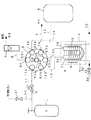
以下本発明の珪素化合物ガス中のシロキサンの分析方法の実施態様を図1、図2に一例を例示して説明する。図1及び図2において1は被測定ガスである珪素化合物ガスSが充填してある容器、2は試料採取管でステンレス鋼製またはガラス製で、冷却時または加熱時に付与する熱の伝達を効果的にするため内部にステンレス鋼製のチップやガラスビーズ等の充填物を充填することが好ましい。該試料採取管2にはこれを冷却するための冷却器で、例えば液体窒素の如き液化ガスを冷媒とし管3Aより弁3Cを介して供給され、冷却した後管3Bより導出される。また4は試料採取管2を加熱するための加熱器である。そしてこれら試料採取管2、冷却器3、及び加熱器4は断熱箱5内に収容するとより好ましい。
【0010】
6は質量分析計であり、7は試料採取管2で捕集した試料ガスを質量分析計6に導くためのヘリウムガスよりなるキャリアーガス源Heと連通しているキャリアーガス導入管であり、8は流量計Fを介して一側の管端8Bが除害して大気に放気する除害筒(図示せず。)に連結するガス排出管である。そしてこれらの機器は6方位置切り替え弁9を介して、後述する試料採取工程、分析測定工程等の工程に応じて連結または遮断し得るよう連結している。
【0011】
即ち、6方位置切り替え弁9は、図3に示す如く弁箱91と該弁箱91に気密にかつ回転可能に装着される弁体92よりなっている。そして前記弁箱91は図3の(a)に図示するように、珪素化合物ガスSの貯蔵容器1と連結している減圧弁10を有する試料導入管11の管端開口11A、試料採取管2の一側2Aと連結している管12の管端開口12A、質量分析計6と連結している管13の管端開口13A、キャリアーガス源Heと連通しているキャリアーガス導入管7の管端開口7A、前記試料採取管2の他側2Bに連結している管14の管端開口14A、そして一側8Bが除害筒(図示せず。)に連結しているガス排出管8の他側管端開口8A等の6ケの管端開口がこの順序に従って円周上に沿って配列されて設けられている。
【0012】
また上記弁箱91に気密にかつ回転可能に装着される弁体92は図3の(b)に図示するように、上記弁箱91に配した6ケの管端開口に弁体92の回転による移動でも常に係合するように、弁箱に設けた管端開口の配置と同一円周上に沿って配置した6ケの連結口93a、93b、93c、93d、93e、そして93fが設けられ、そしてこれら6ケの連結口93は隣り合う連結口と、93aー93b、93c−93d、93e−93fの如く対をなして管路94、95、96でそれぞれ連通せしめて、3組の管路を形成している。
【0013】
このような構造よりなる弁箱91と弁体92とは図3の(c)に図示する如く、弁体92が弁箱91に回転可能にかつ気密を保って装着され一体となって6方位置切り替え弁9を形成し、図1、図2に図示する如き前記各機器を切り替え可能な管路で連設せしめて本発明の珪素化合物ガス中のシロキサンの分析装置を構成している。なお、97は弁体92を回転操作するハンドルである。
【0014】
上記した装置を使用して、珪素化合物ガス中のシロキサンを分析する方法を説明する。まず6方位置切り替え弁9を図1に示す如く、弁体92の連結口93aが弁箱91に設けた珪素化合物ガスSを貯蔵する容器1に連結する導入管11の管端開口11Aに係合するよう設定する。すると弁体92のその他の連結口と弁箱91の管端開口とは、93b−12A、93c−13A、93d−7A、93e−14A、93f−8Aの如くに自ずと係合する。そして、貯蔵容器1−試料採取管2−流量計F−大気放出の流通管路と、キャリア−ガス源He−質量分析計6の流通管路との2つの流通管路が形成される。
【0015】
このような状態でキャリアーガス導入管7より質量分析計6にキャリアーガス源Heからヘリウムガスを流し、一方試料採取管2を100℃以上の温度に加熱器4で加熱すると共に、管20より弁21を介して試料導入管11にヘリウムガスや窒素ガスの如き不活性ガスを供給し、そしてこの不活性ガスを試料採取管2内に流通せしめて流量計Fを介して大気放出する。このようにして試料採取管2内を充分加熱洗浄した後、加熱を停止しついで冷却器3に管端3Aより弁3Cを介して液体窒素の如き冷媒を流して試料採取管2を冷却する。冷却温度は分析対象であるシロキサンを完全に捕獲することが必要であることから、シロキサンの沸点であるー15℃と融点ー144℃の間の温度が好ましい。ー15℃以上の温度ではシロキサンが凝縮せずガス状で試料採取管2を流通して大気に放出され真値が得られない。またー144℃以下の温度ではシロキサンが凝固し、次工程の分析時にこれを気化するのに時間を要するばかりか、冷却のための費用も嵩む等の不都合が生じる。
【0016】
ついで弁21を閉じて不活性ガスの供給を停止するとともに、貯蔵容器1の弁を開いて容器1内の珪素化合物ガスSを減圧弁10、試料導入管11、管12を経て試料採取管2に導入し、そして管14、ガス排出管8、流量計Fを経て管端開口8Bより除害筒(図示せず。)を介して大気に放出される。この間試料採取管2は前記冷却温度に継続して保持されている。またこの間に試料採取管2に流通せしめた珪素化合物ガスSの流量を流量計Fにて計量する。
【0017】
所定の流量を流した後、6方位置切り替え弁9を回転操作(例えば時計と同方向)して、図2に図示した如く93a−8A、93bー11A、93cー12A、93dー13A、93e−7A、93fー14A等の位置に弁体92の各連結口と弁箱91の各管端開口とを係合せしめる。その結果、貯蔵容器1ー流量計Fー大気放出の流通管路とキャリアガス源Heー試料採取管2ー質量分析計6の流通管路との2つの流通管路を形成するように切り替えられ、試料採取管2に導入されていた珪素化合物ガスは容器1より流量計Fを通り管端開口8Bより除害筒で除害された後大気に放出される。一方キャリアーガス源Heからヘリウムガスがキャリアーガス導入管7より管14を経て試料採取管2に導入され、該採取管2を流通して管12、管13を経て質量分析計6に導入される。そして弁3Cを閉じて冷却器3への冷媒の供給を停止して、試料採取管2の冷却を止めるとともに、加熱器4を作動して試料採取管2加熱する。
【0018】
この結果、前記冷却工程で試料採取管2で凝縮して液化されていたり、凝固して固化されていた成分が、温度の上昇とともに各成分特有の融点に従い融解したり、各成分特有の沸点に従い気化したりする。なおシロキサン、及び珪素化合物ガスの沸点と融点を表1に示す。
【表1】

表1に示したようにシロキサンの沸点はー15℃であり、他の珪素化合物ガスの沸点はシロキサンより低温度であったり、高い温度であったりして、その沸点温度にシロキサンと差がある。従って、シロキサンの沸点(ー15℃)より低い沸点温度の組成分は先の工程での冷却温度ー144℃より加熱して温度を徐々に上昇させて行く間にシロキサンの沸点に達するまでに既に気化し、試料採取管に導入されるキャリアガスに同伴されて先んじて質量分析計6に搬送される。また一方、シロキサンの沸点(ー15℃)より高い沸点の組成分はシロキサンの気化するー15℃の温度近辺の温度では未だ気化せず液体状態を保持している。従ってー10〜ー15℃の温度に達すると試料採取管2内に保持されているシロキサンの凝縮液のみが気化し始め、この気化したシロキサンは試料採取管2に導入されているキャリアーガスに同伴されて質量分析計6に搬送される。
【0020】
かくして、珪素化合物ガスとこれに混在しているシロキサンは完全に分離されて質量分析計6に導入され、通常の質量分析計による分析操作でシロキサンの量が測定される。そしてこれで得られたシロキサンの量(m)を試料採取時に試料採取管2に流した珪素化合物ガスSの流量(M)に対する割合m/Mを算出することにより珪素化合物ガスS中のシロキサンの含有濃度が得られる。
【0021】
なお、上記実施態様における試料採取管2の試料珪素化合物ガスSの採取にあたっては、試料採取管2を所定温度に冷却した状態で珪素化合物ガスSを流して、含有するシロキサンを試料採取管2内で凝縮して捕獲し、そしてその間に試料採取管2に流した珪素化合物ガスSの流量を計測して試料を採取するする方法について説明した。しかし本発明はこれに限定されるものでなく、試料採取にあたって試料採取管2を低温に冷却することなく常温状態として珪素化合物ガスSを流して該ガスを採取し、その後試料採取管2を所定の温度に冷却しても良く、この場合試料採取管2は定容量の管とし、そして採取量が定量の管で定まっているので流量の計測は必要ない。
【0022】
また、上記6方位置切り替え弁9の切り替え操作による管路の切り替えは、上記工程、即ち試料採取工程、質量分析計による分析測定工程の2つの工程の順序を繰り返しで切り替えられ、極めて簡便かつ効率よく使用することができる。
【0023】
【実施例】
次に本発明の珪素化合物ガス中のシロキサンの分析を上記図1、図2に図示した装置を使用して行った実施例について説明する。
実施例1:試料採取管2としてステンレス鋼製、容積2cc(管内径5mm)に80メッシュのステンレス鋼製のチップを充填して使用した。そして、6方位置切り替え弁9を図1に示す如く試料採取工程の位置にして、試料採取に先だって試料採取管2を150℃に加熱するとともに管20より不活性ガスとしてヘリウムガスを流し30分間加熱処理をして採取管2内の水分を排除した。続いて試料採取管2の加熱を停止して、冷却器3を作動して試料採取管2をー110℃に冷却した。ついでヘリウムガスの供給を停止し、貯蔵容器1より珪素化合物ガスSとしてモノシランガスを導出し試料採取管2に導きこれに1000cc流通せしめた(流量計Fで測定)。
【0024】
ついで、6方位置切り替え弁9を操作して図2に示す如く管路を質量分析計6による分析測定工程に切り替えるとともに、冷却器3による冷却を停止し加熱器4を作動せしめて試料採取管2を約10℃/分の昇温速さで徐々に昇温した。この結果、キャリアーガス導入管7より供給されるキャリアーガス源Heからヘリウムガスが試料採取管2に導入され、そして前記徐々なる試料採取管2の昇温により、その温度が特定成分の固有の沸点に達するとこれに相当する沸点を有する成分が気化し、しかも低い沸点の成分の順に気化し、ヘリウムガスに同伴されて質量分析計6に搬送される。
【0025】
そこで本実施例では、質量分析器9の質量数をシロキサンの質量数77に固定し、試料採取管2をー110℃から約10℃/分の昇温速度で150℃まで昇温して質量分析計6に搬送されてきた質量数77の成分(シロキサン)を分析した結果を昇温時間[分]に対する質量数77のシロキサンの相対量を図4のグラフで図示する。この相対量を既知の標準ガスにより値付けしたところ、4.96×10ー5ccとなり、採取試料が1000ccであることからその濃度は4.96×10ー8であり即ち49.6ppbの値を得た。
【0026】
実施例の別の例として、試料採取を実施例1では低温で試料採取を行ったのに代えて、定量の試料採取管を使用して常温状態で行う方法について、珪素化合物ガスSに四弗化珪素ガスを使用して行った。
実施例2:ステンレス鋼製の両端に開閉弁Vs(図示せず。)が設けられている1000cc(管の内径8cm、長さ19.9cm)の定量試料採取管2を図1の如き装着し開閉弁Vsを開とし、実施例1と同様に6方位置切り替え弁9を先ず図1の如く試料採取工程の位置として、不活性ガスを流しながら試料採取管2を100℃以上の温度に加熱して採取管内の水分を排除する。ついで試料採取管2を常温まで冷却した後不活性ガスの導入を停止するとともに、貯蔵容器1より常温で四弗化珪素ガス導出して試料採取管2に流通せしめ、時期をみて開閉弁Vsを閉じて試料採取する。引き続き開閉弁Vsを閉じたまま冷却器3を作動して試料採取管2をー110℃まで冷却するとともに、6方位置切り替え弁9を図2の如き位置にして分析測定工程に切り替える。ー110℃の温度になると四弗化珪素は固化される。
【0027】
ついで、冷却を停止し、加熱器4を作動して試料採取管2を10℃/分の昇温速度で加熱するとともに試料採取管2に備え付けの開閉弁Vsを開く。するとキャリアーガス導入管7から供給されているキャリアーガス源Heからヘリウムガスが試料採取管2に導入され、該管2内で気化したガスはヘリウムガスに同伴されて質量分析計6に搬送される。この実施例2では、ー95℃の温度になると固化した四弗化珪素が融解することなしに昇華現象を起こし直ちに気化し、ヘリウムガスに同伴されて質量分析計6を経て大気に排除される。そして更に昇温を続けるとー15℃の温度になると凝縮していたシロキサンが気化し始めヘリウムガスに伴われて質量分析計6に搬送され質量数77の質量数位置でシロキサンの含量が測定される。この結果を図5にグラフで図示する。ここで質量分析計6の質量数をシロキサンに質量数77に固定し、試料採取管2の開閉弁Vs開いてー110℃から10℃/分の昇温速度で昇温し始めてからの昇温時間(分)に伴う質量数77の相対的検出量を表示した。
【0028】
上記図5のグラフで得られた結果を、既知の含量の標準ガスより検量した結果、1.13×10ー5ccの含量を得た。従って1000ccの四弗化珪素中のシロキサン含有濃度は11.3ppbとなる。
また上記二つのの実施例1及び実施例2で得られた分析結果の図4、図5のグラフで、曲線のノイズ幅を感度を高めて測定し、前記グラフの感度目盛りに換算したところノイズ幅は0.36mmであった。この値より前記実施例1、及び実施例2の図1、及び図2のグラフの曲線と濃度の関係を勘案して、本発明の分析方法の検出下限界値を求めた結果、安全率S/N=2としてその検出下限界値は0.3ppbであった。
なお上記実施例1及び実施例2では珪素化合物ガスSとしてモノシラン、四弗化珪素を例示して該各ガス中のシロキサンについて説明したが、本発明はこれに限定されるものでなく、前記表1に示したシロキサンが生成混入される恐れがある珪素化合物ガス中のシロキサンの分析にも勿論適用し得る。
【0029】
【発明の効果】
本発明は上記した通り、分析すべき珪素化合物ガス中のシロキサンを分離するため、従来の如き分離剤を使用したカラムを使用せずにそれぞれの成分の保有する沸点の差により分離するようにし、かつ試料採取管を試料採取前に充分加熱するとともに不活性ガスを流して水分を排除し洗浄するので、従来の如き分離にあたって温度による分離量が変動する等の影響が無く、上記成分の分離を極めて正確に遂行し得、シロキサンの適確な分析が可能となった。しかも従来検出不可能であった数ppbの微量のシロキサンの検出も可能となり、今後益々必要とされる不純物含量が微量な高純度の半導体製造の材料ガスの品質管理に極めて有効に活用し得る。
【図面の簡単な説明】
【図1】本発明の分析装置の試料採取工程にある系統略図である。
【図2】本発明の分析装置の分析測定工程にある系統略図である。
【図3】本発明の分析装置に使用する6方位置切り替え弁の組立図である。
【図4】本発明の分析方法の実施例1の結果を示すグラフである。
【図5】本発明の分析方法の実施例2の結果を示すグラフである。
【図6】従来の分析方法で得られる分離剤カラムの加熱温度の変化に伴うシロキサンの分析値の変化を示すグラフである。
【符号の説明】
1 貯蔵容器、 2 試料採取管、 3 冷却器、 4 加熱器、
6 質量分析計、 7 キャリアーガス導入管、 8 ガス排出管、
9 6方位置切り替え弁、 11 試料導入管、
12、14 試料採取管に連結する管、 13 質量分析計に連結する管、
91 6方位置切り替え弁の弁箱、 92 6方位置切り替え弁の弁体、
93a、93b、93c、93d、93e、93f 連結口、
94、95、96 管路、 S 珪素化合物ガス、 He キャリアーガス源
F 流量計[0001]
BACKGROUND OF THE INVENTION
In the present invention, siloxane, disilane, halides thereof, and silicon compounds such as silicon tetrachloride and silicon tetrafluoride, which are used in the manufacture of silicon semiconductors, are not preferable in terms of the quality of manufactured products. This analysis method and an apparatus for performing this analysis are used effectively for quality evaluation of silicon compound gas to be used.
[0002]
[Prior art]
Silane gases such as silane, disilane, their halides, and silicon tetrachloride and silicon tetrafluoride are used effectively as raw materials for epitaxial growth and growth of silicon oxide and nitride films in semiconductor manufacturing. Yes. In these silicon compound gases, siloxane that adversely affects the quality of the semiconductor to be manufactured is actually mixed, and this is used after being removed. With the high integration of semiconductors, the appearance of a high purity silicon compound gas whose siloxane content has been reduced as much as possible has been desired. At the same time, it has become indispensable to develop an analysis technique in which the lower limit sensitivity of detection of siloxane in the silicon compound gas is increasingly smaller (several ppb or less).
[0003]
However, siloxanes in conventional silicon compound gases are analyzed using thermal conductivity gas chromatography (hereinafter referred to as “TCD-GC”) as a detector. In this method, a stainless steel tube as a separation column is packed with Polapack P or Polapack Q (both trade names manufactured by Waters, USA) made of a porous polymer agent such as divinylbenzene (DVB). Each component is measured separately. According to this method, the detection sensitivity of siloxane is at most 0.5 to 1 ppm (500 to 1000 ppb), and the required number of ppb cannot be detected.
[0004]
That is, in the conventional analysis method by TCD-GC, it is necessary to heat the separation column to a temperature of 70 to 80 ° C. for the analysis of siloxane. The derivation gas from the separation column due to this change in temperature was introduced into a mass spectrometer, and the variation in siloxane content was measured. The results are illustrated in the graph of FIG. The separation agent used was Polapack P, the gas used was monosilane gas, and 5 cc of the same gas was collected and analyzed at each temperature.
[0005]
As apparent from FIG. 6, the amount of siloxane derived from the column differs depending on the temperature of the separation column even when the same gas is flowed. That is, when the temperature is high, the amount increases. When the temperature of the separation column used in the analysis of the gas by TCD-GC is 70 to 80 ° C., the content of siloxane is about 700 to 1200 ppb, and further, the temperature is about 7000 ppb at 100 ° C. It was confirmed that Further, the content value was as low as about 300 ppb at a lower temperature of 60 ° C. and about 60 ppb at 40 ° C. This is thought to be due to the fact that siloxane is produced by reacting with a small amount of moisture remaining on the polymer separating agent of the separation column and the introduced silicon compound, and the amount of the production increases at a high temperature. .
[0006]
[Problems to be solved by the invention]
In the analysis of siloxane in the silicon compound gas by the conventional TCD-GC using the separation column thus heated, the amount of siloxane derived from the column differs depending on the temperature of the separation column, and the true value cannot be judged. When the heating temperature of the separation column used in this analysis method is 70 to 80 ° C., the amount of siloxane becomes 700 ppb or more, and the siloxane content in the silicon compound gas, which will be indispensable in the field in the future, is as small as several ppb. It was impossible to detect even a very small value.
In view of the above circumstances, an object of the present invention is to provide a highly sensitive analysis method and apparatus capable of measuring a siloxane content in a silicon compound gas as small as several ppb.
[0007]
[Means for Solving the Problems]
In order to achieve the above object, the analysis according to
The analysis method according to
4. The silicon compound gas according to any one of
The analysis method according to
[0009]
DETAILED DESCRIPTION OF THE INVENTION
Hereinafter, embodiments of the method for analyzing siloxane in the silicon compound gas of the present invention will be described with reference to FIG. 1 and FIG. 1 and 2, 1 is a container filled with a silicon compound gas S, which is a gas to be measured, 2 is a sampling tube made of stainless steel or glass, and is effective in transferring heat applied during cooling or heating Therefore, it is preferable to fill the inside with a filler such as a stainless steel chip or glass beads. The
[0010]
[0011]
That is, the six-way
[0012]
Further, as shown in FIG. 3 (b), the
[0013]
As shown in FIG. 3C, the
[0014]
Use equipment described above, a method of analyzing a siloxane silicon compound gas. First, as shown in FIG. 1, the 6-
[0015]
In this state, helium gas is allowed to flow from the carrier gas source He to the
[0016]
Next, the
[0017]
After flowing a predetermined flow rate, the six-way
[0018]
As a result, the component that has been condensed and liquefied in the
[Table 1]
As shown in Table 1, the boiling point of siloxane is −15 ° C., and the boiling point of other silicon compound gases is lower or higher than that of siloxane. . Therefore, the component having a boiling point lower than the boiling point of siloxane (−15 ° C.) has already reached the boiling point of the siloxane while gradually raising the temperature by heating from the cooling temperature of −144 ° C. in the previous step. Vaporized and accompanied by the carrier gas introduced into the sampling tube, it is first transported to the
[0020]
Thus, the silicon compound gas and the siloxane mixed therewith are completely separated and introduced into the
[0021]
In collecting the sample silicon compound gas S from the
[0022]
Further, the switching of the pipe line by the switching operation of the six-way
[0023]
【Example】
Next, an example in which the analysis of siloxane in the silicon compound gas of the present invention was performed using the apparatus shown in FIGS. 1 and 2 will be described.
Example 1: The
[0024]
Next, the six-way
[0025]
Therefore, in this example, the mass number of the
[0026]
As another example of the embodiment, a sample is collected at a room temperature using a fixed amount sampling tube instead of sampling at a low temperature in the first embodiment. This was performed using silicon fluoride gas.
Example 2: A 1000 cc (8 cm inner diameter, 19.9 cm long)
[0027]
Next, the cooling is stopped, the
[0028]
The results obtained in the graph of FIG. 5 were calibrated from a standard gas having a known content, and as a result, a content of 1.13 × 10 −5 cc was obtained. Therefore, the siloxane concentration in 1000 cc of silicon tetrafluoride is 11.3 ppb.
In addition, in the graphs of FIGS. 4 and 5 of the analysis results obtained in the above two Examples 1 and 2, the noise width of the curve was measured with increased sensitivity, and converted to the sensitivity scale of the graph, noise was obtained. The width was 0.36 mm. Based on this value, the lower limit value of detection of the analysis method of the present invention was determined in consideration of the relationship between the curves of the graphs of FIG. 1 and FIG. / N = 2 and the lower limit of detection was 0.3 ppb.
In Examples 1 and 2, monosilane and silicon tetrafluoride are exemplified as the silicon compound gas S, and siloxanes in the respective gases have been described. However, the present invention is not limited to this, and the above table is used. Of course, the present invention can be applied to the analysis of siloxane in a silicon compound gas in which the siloxane shown in FIG.
[0029]
【The invention's effect】
As described above, the present invention separates the siloxane in the silicon compound gas to be analyzed, so that the separation is based on the difference in boiling points of the respective components without using a column using a conventional separating agent, In addition, the sampling tube is heated sufficiently before sampling and the inert gas is flowed to remove moisture and clean, so there is no influence of the separation amount due to temperature in the conventional separation, and separation of the above components is possible. It was possible to carry out very accurately and an accurate analysis of siloxane was possible. Moreover, it is possible to detect a few ppb of a small amount of siloxane, which could not be detected in the past, and can be used extremely effectively for quality control of a material gas for manufacturing a high-purity semiconductor with a trace amount of impurities that will be required in the future.
[Brief description of the drawings]
FIG. 1 is a schematic diagram of a system in a sampling process of an analyzer according to the present invention.
FIG. 2 is a system schematic diagram in the analysis measurement process of the analyzer of the present invention.
FIG. 3 is an assembly diagram of a six-way position switching valve used in the analyzer of the present invention.
FIG. 4 is a graph showing the results of Example 1 of the analysis method of the present invention.
FIG. 5 is a graph showing the results of Example 2 of the analysis method of the present invention.
FIG. 6 is a graph showing a change in analytical value of siloxane accompanying a change in heating temperature of a separating agent column obtained by a conventional analytical method.
[Explanation of symbols]
1 storage container, 2 sampling tube, 3 cooler, 4 heater,
6 Mass spectrometer, 7 Carrier gas introduction pipe, 8 Gas discharge pipe,
9 6-way position switching valve, 11 Sample introduction pipe,
12, 14 Tubes connected to the sampling tube, 13 Tubes connected to the mass spectrometer,
91 Valve box of 6-way position switching valve, 92 Valve body of 6-way position switching valve,
93a, 93b, 93c, 93d, 93e, 93f connection port,
94, 95, 96 pipeline, S silicon compound gas, He carrier gas source F flow meter
Claims (6)
Priority Applications (5)
| Application Number | Priority Date | Filing Date | Title |
|---|---|---|---|
| JP04659497A JP3608183B2 (en) | 1997-02-28 | 1997-02-28 | Method and apparatus for analyzing siloxane in silicon compound gas |
| US09/015,780 US5900532A (en) | 1997-02-20 | 1998-01-29 | Method of removing siloxanes from silicon compound gases and apparatus therefor |
| KR1019980005439A KR100243882B1 (en) | 1997-02-20 | 1998-02-20 | Method of removing siloxanes from silicon compound gases and apparatus therefor and silloxane content analyzing apparatus |
| US09/115,541 US5952557A (en) | 1997-02-20 | 1998-07-15 | Apparatus for analyzing a silicon compound gas for siloxane content |
| US09/217,992 US6196050B1 (en) | 1997-02-20 | 1998-12-22 | Method of removing siloxanes from silicon compound gases and apparatus therefor, and siloxane content analyzing method and analyzing apparatus |
Applications Claiming Priority (1)
| Application Number | Priority Date | Filing Date | Title |
|---|---|---|---|
| JP04659497A JP3608183B2 (en) | 1997-02-28 | 1997-02-28 | Method and apparatus for analyzing siloxane in silicon compound gas |
Publications (2)
| Publication Number | Publication Date |
|---|---|
| JPH10239223A JPH10239223A (en) | 1998-09-11 |
| JP3608183B2 true JP3608183B2 (en) | 2005-01-05 |
Family
ID=12751635
Family Applications (1)
| Application Number | Title | Priority Date | Filing Date |
|---|---|---|---|
| JP04659497A Expired - Lifetime JP3608183B2 (en) | 1997-02-20 | 1997-02-28 | Method and apparatus for analyzing siloxane in silicon compound gas |
Country Status (1)
| Country | Link |
|---|---|
| JP (1) | JP3608183B2 (en) |
Cited By (1)
| Publication number | Priority date | Publication date | Assignee | Title |
|---|---|---|---|---|
| WO2021006502A1 (en) * | 2019-07-11 | 2021-01-14 | 정경환 | Sample gas separation apparatus |
Families Citing this family (4)
| Publication number | Priority date | Publication date | Assignee | Title |
|---|---|---|---|---|
| JP5679437B2 (en) * | 2011-03-02 | 2015-03-04 | 国立大学法人東京工業大学 | Odor concentration device |
| JP5827843B2 (en) * | 2011-09-12 | 2015-12-02 | 大陽日酸株式会社 | Method for analyzing impurity concentration in silicon compound gas |
| CN103712831B (en) * | 2014-01-03 | 2015-11-04 | 浙江中宁硅业有限公司 | Use sampling system and the method thereof of gas chromatographic analysis silane |
| CN114200043B (en) * | 2021-12-01 | 2023-09-05 | 中煤科工集团沈阳研究院有限公司 | System and method for detecting coal natural ignition sign gas and gas storage device thereof |
-
1997
- 1997-02-28 JP JP04659497A patent/JP3608183B2/en not_active Expired - Lifetime
Cited By (1)
| Publication number | Priority date | Publication date | Assignee | Title |
|---|---|---|---|---|
| WO2021006502A1 (en) * | 2019-07-11 | 2021-01-14 | 정경환 | Sample gas separation apparatus |
Also Published As
| Publication number | Publication date |
|---|---|
| JPH10239223A (en) | 1998-09-11 |
Similar Documents
| Publication | Publication Date | Title |
|---|---|---|
| US6196050B1 (en) | Method of removing siloxanes from silicon compound gases and apparatus therefor, and siloxane content analyzing method and analyzing apparatus | |
| EP3011310B1 (en) | System for analyzing mercury | |
| JP2580988B2 (en) | Organic matter analyzer and organic matter analysis method | |
| US8062610B2 (en) | Apparatus and methods for use in concentration of gas and particle-laden gas flows | |
| JP3608183B2 (en) | Method and apparatus for analyzing siloxane in silicon compound gas | |
| US3589169A (en) | Method and device for the analysis of gas | |
| JPH06324024A (en) | Separation of hydrocarbon, analysis and device thereof | |
| KR20050103946A (en) | Purifier information retrieval system | |
| US4101282A (en) | Sample conditioner and analyzer | |
| JP2000187027A (en) | Method and device for analyzing trace amount of organic compound | |
| JP4527110B2 (en) | Analyzer having variable volume type ballast chamber and analysis method | |
| JP3672267B2 (en) | Standard gas for trace metal analysis, standard gas preparation device, and standard gas preparation method | |
| JP4909614B2 (en) | Method and apparatus for analyzing trace impurities in hydride gas | |
| CN106098587A (en) | System and method for monitoring pollution thing | |
| Scott et al. | Determination of mercury vapour in air using a passive gold wire sampler | |
| JP2002296269A (en) | Device and method for evaluating water quality for sample water | |
| Endo et al. | Equilibrium of carbon and oxygen in silicon with carbon monoxide in ambient atmosphere | |
| JPH05256842A (en) | Method and device for analyzing small amount of organic compound | |
| JP3659459B2 (en) | Thermal desorption gas analyzer and thermal desorption gas analysis method | |
| US3724169A (en) | Delta t bar spectrometer | |
| JPS626523Y2 (en) | ||
| CN219496275U (en) | Environment-friendly on-line monitoring and sampling equipment for organic matters in waste gas with fixed pollution sources | |
| Fricioni et al. | Inert gas fusion | |
| JP2001244201A (en) | Moisture monitoring device and semiconductor manufacturing device equipped therewith | |
| CN111781088B (en) | Method for detecting hydrogen content in solid metal |
Legal Events
| Date | Code | Title | Description |
|---|---|---|---|
| A977 | Report on retrieval |
Free format text: JAPANESE INTERMEDIATE CODE: A971007 Effective date: 20040402 |
|
| A131 | Notification of reasons for refusal |
Free format text: JAPANESE INTERMEDIATE CODE: A131 Effective date: 20040511 |
|
| A521 | Written amendment |
Free format text: JAPANESE INTERMEDIATE CODE: A523 Effective date: 20040602 |
|
| TRDD | Decision of grant or rejection written | ||
| A01 | Written decision to grant a patent or to grant a registration (utility model) |
Free format text: JAPANESE INTERMEDIATE CODE: A01 Effective date: 20040907 |
|
| A61 | First payment of annual fees (during grant procedure) |
Free format text: JAPANESE INTERMEDIATE CODE: A61 Effective date: 20041001 |
|
| R150 | Certificate of patent or registration of utility model |
Free format text: JAPANESE INTERMEDIATE CODE: R150 |
|
| FPAY | Renewal fee payment (event date is renewal date of database) |
Free format text: PAYMENT UNTIL: 20071022 Year of fee payment: 3 |
|
| FPAY | Renewal fee payment (event date is renewal date of database) |
Free format text: PAYMENT UNTIL: 20081022 Year of fee payment: 4 |
|
| FPAY | Renewal fee payment (event date is renewal date of database) |
Free format text: PAYMENT UNTIL: 20091022 Year of fee payment: 5 |
|
| FPAY | Renewal fee payment (event date is renewal date of database) |
Free format text: PAYMENT UNTIL: 20091022 Year of fee payment: 5 |
|
| FPAY | Renewal fee payment (event date is renewal date of database) |
Free format text: PAYMENT UNTIL: 20091022 Year of fee payment: 5 |
|
| FPAY | Renewal fee payment (event date is renewal date of database) |
Free format text: PAYMENT UNTIL: 20101022 Year of fee payment: 6 |
|
| FPAY | Renewal fee payment (event date is renewal date of database) |
Free format text: PAYMENT UNTIL: 20101022 Year of fee payment: 6 |
|
| FPAY | Renewal fee payment (event date is renewal date of database) |
Free format text: PAYMENT UNTIL: 20111022 Year of fee payment: 7 |
|
| FPAY | Renewal fee payment (event date is renewal date of database) |
Free format text: PAYMENT UNTIL: 20111022 Year of fee payment: 7 |
|
| FPAY | Renewal fee payment (event date is renewal date of database) |
Free format text: PAYMENT UNTIL: 20121022 Year of fee payment: 8 |
|
| FPAY | Renewal fee payment (event date is renewal date of database) |
Free format text: PAYMENT UNTIL: 20121022 Year of fee payment: 8 |
|
| FPAY | Renewal fee payment (event date is renewal date of database) |
Free format text: PAYMENT UNTIL: 20121022 Year of fee payment: 8 |
|
| FPAY | Renewal fee payment (event date is renewal date of database) |
Free format text: PAYMENT UNTIL: 20131022 Year of fee payment: 9 |
|
| R250 | Receipt of annual fees |
Free format text: JAPANESE INTERMEDIATE CODE: R250 |
|
| R250 | Receipt of annual fees |
Free format text: JAPANESE INTERMEDIATE CODE: R250 |
|
| R250 | Receipt of annual fees |
Free format text: JAPANESE INTERMEDIATE CODE: R250 |
|
| R250 | Receipt of annual fees |
Free format text: JAPANESE INTERMEDIATE CODE: R250 |
|
| EXPY | Cancellation because of completion of term |