JP3607072B2 - Fireproof damper device - Google Patents
Fireproof damper device Download PDFInfo
- Publication number
- JP3607072B2 JP3607072B2 JP08573798A JP8573798A JP3607072B2 JP 3607072 B2 JP3607072 B2 JP 3607072B2 JP 08573798 A JP08573798 A JP 08573798A JP 8573798 A JP8573798 A JP 8573798A JP 3607072 B2 JP3607072 B2 JP 3607072B2
- Authority
- JP
- Japan
- Prior art keywords
- damper
- thermal fuse
- dampers
- support shaft
- fire
- Prior art date
- Legal status (The legal status is an assumption and is not a legal conclusion. Google has not performed a legal analysis and makes no representation as to the accuracy of the status listed.)
- Expired - Fee Related
Links
- 238000009423 ventilation Methods 0.000 claims description 41
- 210000002105 tongue Anatomy 0.000 claims description 19
- 230000002093 peripheral effect Effects 0.000 claims description 14
- 239000000463 material Substances 0.000 claims description 12
- 239000012943 hotmelt Substances 0.000 claims description 10
- 238000005452 bending Methods 0.000 claims description 5
- 230000008018 melting Effects 0.000 claims description 5
- 238000002844 melting Methods 0.000 claims description 5
- 238000003780 insertion Methods 0.000 claims description 2
- 230000037431 insertion Effects 0.000 claims description 2
- 230000009970 fire resistant effect Effects 0.000 claims 1
- 238000004519 manufacturing process Methods 0.000 description 9
- 230000000903 blocking effect Effects 0.000 description 6
- 238000009434 installation Methods 0.000 description 5
- 238000000034 method Methods 0.000 description 3
- 230000002265 prevention Effects 0.000 description 3
- 238000005304 joining Methods 0.000 description 2
- 230000000149 penetrating effect Effects 0.000 description 2
- 230000000694 effects Effects 0.000 description 1
- 239000006023 eutectic alloy Substances 0.000 description 1
- 230000001771 impaired effect Effects 0.000 description 1
- 238000003754 machining Methods 0.000 description 1
- 239000002184 metal Substances 0.000 description 1
- 238000009751 slip forming Methods 0.000 description 1
- 239000000779 smoke Substances 0.000 description 1
Images


Landscapes
- Air-Flow Control Members (AREA)
Description
【0001】
【発明の属する技術分野】
本発明は、火災の類焼などを防ぐための防火区画を貫通する部分、たとえば通風ダクトに取り付ける防火ダンパーに関するものである。
【0002】
【従来の技術】
近年、火災時などに類焼を防ぐため防火ダンパーが作動したとき確実に通風路を遮断する開閉装置が求められている。
【0003】
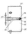
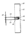
このようなことから、従来この種の防火ダンパーは、たとえば、特開平8−308949号公報、あるいは実公平2−11087号に示すように構成されていた。以下、その構成について図11および図12を参照しながら説明する。
【0004】
図に示すように、壁等を貫通するように設けられる円筒状の枠体101は両端を開口し、通風路102を形成している。この枠体101には通風路102を開閉する2枚の半円形状のバタフライダンパー103をこのバタフライダンパー103に設けられたカール状蝶番104を介して軸105によって回動自在に支持している。前記2枚のバタフライダンパー103が前記通風路102を遮断するように一平面をなす方向に張力を有するスプリング106が前記軸105に設けられ、この張力に対抗して2枚のバタフライダンパー103の一端に温度ヒューズ107が張架されている。なお、108はダンパーが閉じたときに、ダンパーを遮断位置に位置決めするストッパーである。
【0005】
上記構成において、異常高温空気が通風路102に流れ込むと、温度ヒューズ107が溶断し、バタフライダンパー103がスプリング106に働く張力を起動力として作動し、ストッパー108に当たるところまで回動し、通風路102を遮断する。
【0006】
【発明が解決しようとする課題】
このような従来の防火ダンパーでは、熱溶断時、バタフライダンパー103の回動方向に対して、温度ヒューズ107の取付け位置や、動作のばらつきによって、この温度ヒューズ107は複数の部材として前記枠体101内で分割、ばらばらに飛散され、その部材がこの枠体101とバタフライダンパー103との間に挟まって遮断動作の確実性に疑問があるばかりでなく、スプリング106に働く外側に開こうとする張力により温度ヒューズ107を係止していることから、張力に逆らった力が外から加わった場合、容易に外れるという危険性がある。
【0007】
また、溶断温度の異なる温度ヒューズは、72℃から120℃の溶断温度の異なる共晶合金等を接合材とした同一形状で、取付け方法も同一のため、誤って取り付けられる恐れがある。
【0008】
また、バタフライダンパー103に設けられたカール状蝶番104で軸105を介して回動自在とし、通風時、2枚のバタフライダンパー103の間には前記カール状蝶番104が連続的に形成され、通風空間がない事から通気抵抗損失も大きくなるとともに、温度ヒューズ面を通過する風の量も少なくなり熱溶断の機能も損なわれるという問題がある。さらに、カール状蝶番104を作ることは寸法精度と製造コストの点から容易でないという課題があった。
【0009】
またバタフライダンパー103の大きさに応じてスプリング106の張力を変える必要があり1個のスプリング106で対応することは容易でなく、このスプリング106の線径を変えて種類を増やすなどの対策が必要であった。
【0010】
本発明は上記課題を解決するもので、ダンパーの遮断動作の安定性を確保する防火ダンパー装置を提供することを第1の目的とする。
【0011】
第2の目的は、溶断温度の異なる温度ヒューズの誤った取付けを未然に防ぐことにある。
【0012】
第3の目的は、カール状蝶番を廃止してダンパーの間の通風路を確保し通気抵抗を低減することと、ダンパーの寸法精度を保ち、製造コストを低減することのできる防火ダンパー装置を提供することを目的とする。
【0013】
第4の目的は、ダンパーのサイズの大きさに対応した、適切なスプリングの張力を容易に確保できる防火ダンパー装置を提供することを目的とする。
【0014】
【課題を解決するための手段】
この課題を解決するために、本発明の上記第1の目的を達成するための第1の手段は、両端の開口部を連通する通風路が形成された枠体と、この枠体の内部に前記通風路と直角に固定された支軸と、この支軸を境に回動自在に設けた2枚のダンパーと、この2枚のダンパーを常時押し広げ、前記通風路を遮断する方向に働くよう前記支軸を介して取り付けられ、その両端を前記2枚のダンパーに圧接した適宜の数のスプリングと、このスプリングに抗して、前記2枚のダンパーの間にも通風路を形成するよう、一定の間隔を開けて互いに重なる状態に繋止する熱溶融形温度ヒューズと、この温度ヒューズには前記2枚のダンパーの外周端部よりダンパーの板厚に沿って圧入もしくは挿入して咬合する形の繋止部を設け、熱溶融時ダンパーと一体となって2もしくは複数に分割し、回動するよう取り付ける構成としたものである。
【0015】
また、第1の目的を達成するための第2の手段は、温度ヒューズは、細長状の板材を折り曲げて形成された2つの部品を、左右一対の形状に接合材で熱溶融接合した構成とする。
【0016】
また、第1の目的を達成するための第3の手段は、温度ヒューズの一部に設けた繋止部は、2つの凸状切り起こし舌片がダンパーの板厚に沿って互いに向き合う形に設け、このダンパーに設けた凹部に咬合するよう形成した構成とする。
【0017】
また、第1の目的を達成するための第4の手段は、温度ヒューズは同一形状の2つの部品からの構成としたものである。
【0018】
また、第1の目的を達成するための第5の手段は、2枚のダンパーに重ね合わせた状態で、ダンパーの外周端部に接する外側背中合わせの位置に所定の複段の凹部を設け、一段目の凹部は温度ヒューズの一面と凹設する形状を有し、二段目の凹部は前記温度ヒューズに設けた凸状切り起こし舌片に咬合する形状を設けた構成としたものである。
【0019】
また、第2の目的を達成するための第6の手段は、温度ヒューズには2つの凸状切り起こし舌片により形成された長穴開口部を設け、ダンパーには前記長穴開口部に挿通可能とする突起部をダンパー外周端部に設け、前記温度ヒューズの溶断温度の種類により、前記温度ヒューズの長穴開口部と前記ダンパー突起部との挿通寸法の、長さ方向の寸法を変える構成としたものである。
【0020】
また、第3の目的を達成するための第7の手段は、ダンパーのヒンジ部を支軸に直交する形の支軸貫通穴付舌片とし、前記ダンパーと一体でこのダンパー下端部より直角に突出して適宜の数設けた構成としたものである。
【0021】
また、第3の目的を達成するための第8の手段は、ダンパーは左右一対の同一形状の2つの部品からの構成としたものである。
【0022】
また、第4の目的を達成するための第9の手段は、スプリングは支軸を介して取り付けられ、適宜の数設けた支軸貫通穴付舌片形状のヒンジ部の間に適宜の数設けた構成としたものである。
【0023】
【発明の実施の形態】
本発明は上記した第1の手段の構成により、通風路を通る空気が異常高温になったとき、複数の部品を熱溶融接合した熱溶融形温度ヒューズは分割され、この分割された温度ヒューズは2枚のダンパーに繋止された状態で、ダンパーに圧接したスプリングにより、2枚のダンパーと一体となって同一平面になるように開き、枠体の通風路を遮断する動作は確実に行われることとなる。
【0024】
また、第2の手段の構成により、通風路を通る空気が異常高温になったとき、温度ヒューズは、細長状の板材で折り曲げた2つの部品を左右一対の形状に接合材で熱溶融接合としているため、熱溶融するとともに繋止している部分が左右均等に解除され、ダンパーに圧接したスプリングの作用により、2枚のダンパーと一体となって同一平面になるように開き、ダンパーと枠体に挟まれることなく確実に枠体の通風路を遮断するのである。
【0025】
また、第3の手段の構成により、温度ヒューズとダンパーの繋止方法は、温度ヒューズに設けられた2つの凸状切り起こし舌片が、ダンパーの板厚に沿って互いに向き合う形に設けられ、ダンパーの外周端部よりダンパーの板厚に沿って圧入もしくは挿入して、ダンパーに設けた凹部に確実に咬合する形となる。
【0026】
また、第4の手段の構成により、温度ヒューズは同一形状の2つの部品で構成されているため、2枚のダンパーと一体となって動作する上でばらつきがなくより確実な動作が可能となるとともに、部品の統一化が図れ、製造コストの低減ができる。
【0027】
また、第5の手段の構成により、2枚のダンパーの外側背中合わせの位置に所定の複段の凹部を設け、一段目の凹部は温度ヒューズの一面と凹設する形となっているため2枚のダンパーが枠体の通風路を遮断する動作をした場合、ダンパーと枠体との間に温度ヒューズが飛び出して挟まれることがなく、隙間が発生せず、確実に枠体の通風路を遮断することとなる。
【0028】
また、第6の手段の構成により、温度ヒューズに設けた長穴開口部の寸法と、ダンパー外周端部に設けた突起の寸法が互いに挿通可能とするよう、温度ヒューズの溶断温度の種類に応じて変えているため、溶断温度の間違った取付けが物理的に防止できることとなる。
【0029】
また、第7の手段の構成により、ダンパーのヒンジ部をダンパー下端部から支軸に対して直交した形で作られるため、通風時カール状蝶番に比較してダンパー間の通風路を確保でき、通気抵抗を低減することができる。さらにヒンジ部の加工がより精度のあるものとなり、製造コストを低減できる。
【0030】
また、第8の手段の構成により、ダンパーは同一形状の2つの部品で構成されているため、部品の統一化が図れ、製造コストを低減できる。
【0031】
また、第9の手段の構成により、スプリングは支軸を介して適宜の数設けることができ、ダンパーの大小に応じて適切な数のレイアウトが可能となる。
【0032】
【実施例】
(実施例1)
以下、本発明の実施例1について、図1〜図10を参照しながら説明する。
【0033】
図に示すように、1は筒状の枠体で両端を開口し、通風路2を形成している。前記枠体1には、通風路2を開閉するダンパー3を設けている。このダンパー3は円板を半割り状にした形状で、一対の半割り板がそれぞれ枠体1に固定された支軸4に回動自在に支持されている。支軸4には適宜の数のスプリング5を巻きつけ、このスプリング5の両端は、2枚のダンパー3の間にも一定の通風路6を形成する形で、一定の間隔を開けて互いに重ねられた2枚のダンパー3を蝶開きするように力を加えている。そして一定の間隔を開けて互いに重ねられた状態にある2枚のダンパー3の外周端部7には、2つの凸状切り起こし舌片8、9がダンパー3の板厚に沿って互いに向き合う形に設けられ、この2つの凸状切り起こし舌片8、9を介してダンパー3の外周端部7に設けた複段の凹凸部10に圧入あるいは挿入して咬合・繋止する形状の熱溶融形温度ヒューズ11を設けている。
【0034】
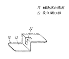
そしてこの温度ヒューズ11は細長状の板材12を折り曲げて形成された同一形状の2つのヒューズ部品13を、左右一対の形に接合材14で一定の面積部分が熱溶融接合されており、熱溶融時ダンパー3と一体となって、2もしくは複数に分割し、回動するように取り付ける構成としている。
【0035】
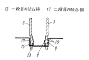
また2枚のダンパー3は、この外周端部7の外側背中合わせの位置に設けた複段の凹凸部10に温度ヒューズ11を圧入あるいは挿入して咬合・繋止するよう、一段目の凹凸部15は温度ヒューズ11の一平面16と多少の隙間をあけて凹設する形状とし、二段目の凹凸部17は温度ヒューズ11に設けた凸状切り起こし舌片8、9に凹設咬合・繋止する構成としている。
【0036】
なお18はダンパー3が開いたときに、通風路2を遮断する位置にダンパー3を位置決めするストッパーであり、19は防火ダンパー本体をダクト内に係止する抜け止め金具であり、30は空気漏れ防止のカバー板であり、31はダンパーを所定の位置に保持する保持片である。
【0037】
上記構成により、枠体1の通風路2を通る空気が異常高温になったとき、熱溶融接合している温度ヒューズ11は、2もしくは複数に熱溶断し、接合している部分が解除され、ダンパー3に圧接したスプリング5の作用により、ダンパー3と一体となって分割回動し、通風路2を遮断するように一平面にダンパー3は開く。そして開いたダンパー3はストッパー18で位置決めされて、完全に枠体1の通風路2を遮断することとなる。
【0038】
また、熱溶融接合している温度ヒューズ11は、細長状の板材12をその外側端面部20が枠体1およびストッパー18に当たらないよう離れる位置に折り曲げた2つのヒューズ部品13を、左右一対の形状に接合材14で熱溶融接合されているので、熱溶融時ダンパー3と一体となって分割回動し、枠体1およびストッパー18に当たることなく、枠体1の通風路2を遮断することとなる。
【0039】
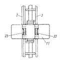
また、熱溶融接合している温度ヒューズ11に設けた繋止部21は、2つの凸状切り起こし舌片8、9がダンパー3の板厚に沿って互いに向き合う形に設けられているため、温度ヒューズ11をダンパー3の板厚に沿って圧入・挿入することによりその切り起こし舌片8、9はダンパー3に設けた複段の凹凸部10に沿って確実に咬合することとなる。
【0040】
また、温度ヒューズ11は同一形状の2つのヒューズ部品13を接合材14で熱溶融接合されているため、熱溶融してダンパー3と一体となって分割回動するとき同じ軌跡で左右均等に動作することとなる。
【0041】
このように本発明の実施例1の防火ダンパー装置によれば、ダンパーの動作の安定性を確保でき、確実に通風路を遮断できるものとなる。
【0042】
(実施例2)
つぎに、本発明の実施例2について、図4〜図10を参照しながら説明する。
【0043】
なお、上記実施例1と同一構成要素には同一符号を付し、詳細な説明は省略する。
【0044】
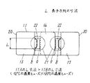
本実施例は図に示すように、温度ヒューズ11には2つの凸状切り起こし舌片8、9により形成された長穴開口部22を設けるとともに、2枚のダンパー3には温度ヒューズ11の長穴開口部22に挿通可能とする突起部23をダンパー3の外周端部7の外側に突出して設け、温度ヒューズ11の溶断温度の種類により、長穴開口部22と突起部23の長手方向の寸法Lを変えた点に特徴がある。
【0045】
上記構成により、温度ヒューズ11の溶断温度の種類により、例えば72℃仕様と120℃仕様との違いで不安全側に誤った取付けが不可能なように(120℃仕様の温度ヒューズ11Bが72℃仕様のヒューズ11Aに取付け不可能なように)120℃仕様の温度ヒューズ11Bの長穴開口部22と突起部23の長手方向の寸法Lを72℃仕様のヒューズ11Aよりも小さく変えたことで、不安全側に誤った取付けが物理的に不可能となる。
【0046】
このように、本発明の実施例2の防火ダンパー装置によれば、不安全側に誤った取付けが物理的に不可能となるため、より安全な防火対策が可能となる。
【0047】
(実施例3)
つぎに、本発明の実施例3について、図1〜図3を参照しながら説明する。
【0048】
なお、上記実施例1および2と同一構成要素には同一符号を付し、その詳細な説明は省略する。
【0049】
本実施例は図に示すように、ダンパー3のヒンジ部24を支軸4に直交する形で、ダンパー3の下端部から一体となって直角に突出するよう折り曲げて形成された支軸4に貫通するヒンジ穴25を有する舌片形状とし、一定の間隔をあけて適宜の数設けている。また、このダンパー3は左右一対の同一形状の2つの部品で構成され、枠体1に回動自在となるよう、ヒンジ穴25を貫通した支軸4で蝶着されている。上記構成において2枚のダンパー3は一定の間隔をあけて互いに重なる状態にある位置のとき、一定の通風路6をその間に確保できることとなる。
【0050】
上記構成により、カール状蝶番に比較して2枚のダンパー3の間に一定の通風路6を確保できるので通気抵抗は小さくなる。また温度ヒューズ11に当たる空気も増加するため、溶断性能の向上安定が図れる。またヒンジ部24の加工精度が向上し、ダンパー3は同一形状の2つの部品3−1、3−2で構成されることとなり、部品の統一化と、製造コストの低減が図れる。
【0051】
(実施例4)
つぎに、本発明の実施例4について、図1〜図4を参照しながら説明する。
【0052】
なお、上記実施例1、2および3と同一構成要素には同一符号を付し、その詳細な説明は省略する。
【0053】
本実施例は図に示すように、ダンパー3のヒンジ部24は支軸4に直角に突出して形成され、スプリング5はヒンジ部24の間に一定の間隔をあけて適宜の数設けられている。ダンパー3は、枠体1に回動自在となるよう、ヒンジ穴25を貫通した支軸4で蝶着されている。上記構成において2枚のダンパー3のサイズが大きいタイプの時は一定の間隔をあけてスプリング5の数を増やすことにより、ダンパー3の必要とされる適正な張力を容易に得ることができる。
【0054】
上記構成により、スプリング5は支軸4を介してヒンジ部24の間に適宜の数設けることが可能となり、ダンパーの大小に応じて適切な数のレイアウトが可能となり、遮断機能の向上安定が図れるとともに、部品の標準化/統一化と、製造コストの低減が図れる。
【0055】
【発明の効果】
以上の実施例から明らかなように、本発明によれば通風路を通る空気が異常高温になったとき、複数の部品を熱溶融接合した熱溶融形温度ヒューズは分割され、この分割された温度ヒューズは2枚のダンパーに繋止された状態で、ダンパーに圧接したスプリングにより、2枚のダンパーと一体となって同一平面になるように開くことになるので、温度ヒューズがバラバラに飛び散ってダンパーと枠体との間に挟まれることなく、ダンパーの遮断動作の安定性が確保され、通風路を遮断する動作が確実に行われることで煙等の進行が阻止され、より安全性が向上されることとなる。
【0056】
また、温度ヒューズを、細長状の板材を折り曲げて形成された2つのヒューズ部品を、左右一対の形状に接合材で熱溶融接合しているので、熱溶融するとともに、繋止された部分が左右均等に解除され、ダンパーに圧接したスプリングにより、2枚のダンパーと一体となって同一平面になるように開くことになるので、ダンパーと枠体とに挟まれることなくダンパーの遮断動作の安定性が確保されより安全性が向上されることとなる。
【0057】
また、温度ヒューズとダンパーの繋止方法は、温度ヒューズに設けられた2つの凸状切り起こし舌片が、ダンパーの板厚に沿って互いに向き合う形に設けられ、ダンパーの外周端部よりダンパーの板厚に沿って圧入もしくは挿入し、ダンパーに設けた凹部に確実に咬合することとなり、ダンパーと一体となって同一平面になるように開くことになるので、遮断動作の安定性が確保されより安全性が向上されることとなる。
【0058】
また、温度ヒューズは同一形状の2つのヒューズ部品で構成されているため、熱溶融時の分割とともにダンパーと一体となって同一平面に左右均等に回動軌跡を描くため、遮断動作の安定性が確保されより安全性が向上されるとともに、部品の統一化が図れ、よりコストの安い防火ダンパー装置を提供することができる。また、2枚のダンパーの外側背中合わせの位置に2段の凹部を設ける構成とし、1段目の凹部を温度ヒューズの一面と凹設する形となっていることにより、ダンパーが通風路を遮断する動作をした時、ダンパーと枠体との間に温度ヒューズの一面が挟まれることがなく、隙間が発生せず、確実に枠体の通風路を遮断し安全性がより向上する。
【0059】
また、温度ヒューズをダンパーに取り付ける場合に、温度ヒューズに設けた長穴開口部とダンパーの外周端部に設けた突起の寸法が互いに挿通できるよう、温度ヒューズの溶断温度の種類に応じて変えていることにより、溶断温度の異なる温度ヒューズの間違った取付けが物理的に防止でき、適正な温度による溶断動作が行われ、さらに安全性が向上する。
【0060】
また、ダンパーのヒンジ部をダンパー下端部から一定の距離をおいて支軸に対して直交した形で作られるため、カール状蝶番に比べてダンパー間の通風路を確保でき、通気抵抗をさらに低減することができるとともに、温度ヒューズに当たる通風空気量も増加するので溶断性能の向上が図れる。また、ヒンジ部の加工がより精度のあるものとなり、製造コストの低減になる。
【0061】
また、ダンパーは同一形状の2つのヒューズ部品で構成されているため、部品の統一化が図れ金型費も半減でき、製造コストの低減になる。
【0062】
さらに、スプリングは支軸を介してヒンジ間にダンパーのサイズに合わせて適宜の数だけ設けることができ、1種類のスプリングで、より適切な所要張力が容易に得られることとなる。
【図面の簡単な説明】
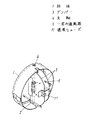
【図1】本発明の実施例1、3、4の防火ダンパー装置の組み立て斜視図
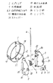
【図2】同分解斜視図
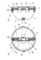
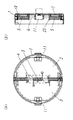
【図3】(a)同ダンパー復帰セット時の正面図
(b)同ダンパー復帰セット時の縦断面図
【図4】(a)同実施例1、2、4の防火ダンパー装置のダンパー作動時の正面図
(b)同ダンパー作動時の縦断面図
【図5】同実施例1、2の温度ヒューズの断面図
【図6】同ヒューズ部品の斜視図
【図7】同温度ヒューズの正面図
【図8】同温度ヒューズとダンパーの咬合・繋止部分の断面拡大図
【図9】同温度ヒューズとダンパーの咬合・繋止部分の正面拡大図
【図10】同温度ヒューズとダンパーの咬合・繋止部分の側面拡大図
【図11】従来の他の防火ダンパー装置を示す断面図
【図12】同他の防火ダンパー装置を示す断面図
【符号の説明】
1 枠体
3 ダンパー
4 支軸
5 スプリング
6 一定の通風路
7 外周端部
8、9 凸状切り起こし舌片
10 複段の凹凸部
11 温度ヒューズ
11A 72℃の温度ヒューズ
11B 120℃の温度ヒューズ
12 細長状の板材
13 ヒューズ部品
14 接合材
15 一段目の凹凸部
16 一平面
17 二段目の凹凸部
18 ストッパー
19 抜け止め金具
20 外側端面部
21 繋止部
22 長穴開口部
23 突起部
24 ヒンジ部
25 ヒンジ穴
L 長手方向の寸法[0001]
BACKGROUND OF THE INVENTION
The present invention relates to a fire-proof damper that is attached to a portion that penetrates a fire-proof section, for example, a ventilation duct, for preventing fire burning.
[0002]
[Prior art]
In recent years, there has been a demand for an opening / closing device that reliably blocks an air passage when a fire damper is activated in order to prevent similar burning in a fire or the like.
[0003]
For this reason, this type of fire damper is conventionally configured as shown in, for example, JP-A-8-308949 or JP-A-2-11087. Hereinafter, the configuration will be described with reference to FIGS. 11 and 12.
[0004]
As shown in the figure, a
[0005]
In the above configuration, when abnormally high temperature air flows into the
[0006]
[Problems to be solved by the invention]
In such a conventional fireproof damper, the
[0007]
In addition, the thermal fuses having different fusing temperatures have the same shape using eutectic alloys or the like having different fusing temperatures from 72 ° C. to 120 ° C. as the joining material, and the attachment method is the same, so there is a possibility that they are erroneously attached.
[0008]
Further, a
[0009]
In addition, it is necessary to change the tension of the
[0010]
This invention solves the said subject, and sets it as the 1st objective to provide the fireproof damper apparatus which ensures the stability of the interruption | blocking operation | movement of a damper.
[0011]
The second purpose is to prevent erroneous installation of thermal fuses having different fusing temperatures.
[0012]
The third purpose is to provide a fireproof damper device that eliminates the curled hinge to secure the ventilation path between the dampers to reduce the airflow resistance, and maintains the dimensional accuracy of the damper to reduce the manufacturing cost. The purpose is to do.
[0013]
The fourth object is to provide a fireproof damper device that can easily secure an appropriate spring tension corresponding to the size of the damper.
[0014]
[Means for Solving the Problems]
In order to solve this problem, a first means for achieving the first object of the present invention includes a frame body in which an air passage that communicates openings at both ends is formed, and an inside of the frame body. A support shaft fixed at right angles to the ventilation path, two dampers rotatably provided around the support shaft, and the two dampers are always expanded to work in a direction to block the ventilation path. An appropriate number of springs attached through the support shaft and having both ends pressed against the two dampers, and an air passage between the two dampers is formed against the springs. A hot-melt type thermal fuse that is fixed in a state of being overlapped with each other at a predetermined interval, and this thermal fuse is press-fitted or inserted along the thickness of the damper from the outer peripheral ends of the two dampers to be engaged. A shape-shaped locking part is provided to match the heat melting damper. And it is divided two or a plurality, in which a structure for mounting to rotate.
[0015]
Further, the second means for achieving the first object is that the thermal fuse has a configuration in which two parts formed by bending a long and narrow plate material are heat-melted and bonded into a pair of left and right shapes with a bonding material. To do.
[0016]
The third means for achieving the first object is that the locking portion provided in a part of the thermal fuse is formed so that the two convex cut and raised tongues face each other along the thickness of the damper. It is set as the structure formed so that it might bite in the recessed part provided in this damper and this damper.
[0017]
Further, as a fourth means for achieving the first object, the thermal fuse is composed of two parts having the same shape.
[0018]
Further, the fifth means for achieving the first object is to provide a predetermined multi-stage recess at the back-to-back position in contact with the outer peripheral end of the damper in a state of being superimposed on the two dampers. The concave portion of the eye has a shape that is recessed with one surface of the thermal fuse, and the concave portion of the second stage has a configuration in which a convex cut and raised portion provided on the thermal fuse is engaged with the tongue piece.
[0019]
Further, as a sixth means for achieving the second object, the thermal fuse is provided with an elongated hole opening formed by two convex cut and raised tongue pieces, and the damper is inserted into the elongated hole opening. Proposed projections are provided on the outer peripheral end of the damper, and the length of the insertion dimension between the elongated hole opening of the thermal fuse and the damper projection is changed depending on the fusing temperature of the thermal fuse. It is what.
[0020]
Further, a seventh means for achieving the third object is that the damper hinge portion is a tongue piece with a shaft through hole perpendicular to the shaft, and is integrated with the damper at a right angle from the lower end of the damper. This is a configuration in which an appropriate number of protrusions are provided.
[0021]
Further, as an eighth means for achieving the third object, the damper is composed of a pair of left and right parts having the same shape.
[0022]
A ninth means for achieving the fourth object is that a spring is attached via a support shaft, and an appropriate number is provided between tongue-shaped hinge portions with support shaft through holes provided in an appropriate number. This is a configuration.
[0023]
DETAILED DESCRIPTION OF THE INVENTION
In the present invention, when the air passing through the ventilation path becomes abnormally high temperature due to the configuration of the first means described above, the thermal melting type thermal fuse in which a plurality of parts are hot melt bonded is divided. With the spring held in contact with the two dampers, the spring is pressed against the damper to open together with the two dampers so as to be in the same plane, and the operation of blocking the ventilation path of the frame is reliably performed. It will be.
[0024]
Further, due to the configuration of the second means, when the air passing through the ventilation path becomes abnormally high temperature, the thermal fuse is formed by joining two parts bent by an elongated plate material into a pair of left and right shapes as a hot melt joint with a joining material. Therefore, the part that is melted and locked is released evenly on the left and right sides, and the spring and the damper pressed against the damper are opened so as to be integrated with the two dampers so that they are in the same plane. The air passage of the frame is surely blocked without being caught between the two.
[0025]
Further, according to the configuration of the third means, the method for locking the thermal fuse and the damper is provided in such a manner that the two convex cut and raised tongue pieces provided in the thermal fuse face each other along the plate thickness of the damper, It is press-fitted or inserted along the plate thickness of the damper from the outer peripheral end of the damper, and is surely engaged with a recess provided in the damper.
[0026]
In addition, since the thermal fuse is composed of two parts having the same shape by the configuration of the fourth means, there is no variation when operating integrally with the two dampers, and a more reliable operation is possible. At the same time, it is possible to unify parts and reduce manufacturing costs.
[0027]
In addition, the fifth means is configured so that a predetermined double-stage recess is provided at the back-to-back position of the two dampers, and the first-stage recess is recessed with one surface of the thermal fuse. When the damper operates to block the ventilation path of the frame body, the thermal fuse does not pop out between the damper and the frame body, and there is no gap, ensuring that the ventilation path of the frame body is blocked. Will be.
[0028]
Further, according to the configuration of the sixth means, depending on the type of fusing temperature of the thermal fuse, the dimension of the slot opening provided in the thermal fuse and the dimension of the projection provided on the outer peripheral end of the damper can be inserted into each other. Therefore, incorrect installation of the fusing temperature can be physically prevented.
[0029]
Moreover, since the hinge portion of the damper is made in a shape orthogonal to the support shaft from the lower end portion of the damper by the configuration of the seventh means, the ventilation path between the dampers can be secured compared to the curled hinge at the time of ventilation, Ventilation resistance can be reduced. Further, the machining of the hinge portion becomes more accurate, and the manufacturing cost can be reduced.
[0030]
Moreover, since the damper is composed of two parts having the same shape by the configuration of the eighth means, the parts can be unified and the manufacturing cost can be reduced.
[0031]
Further, according to the configuration of the ninth means, an appropriate number of springs can be provided via the support shaft, and an appropriate number of layouts can be made according to the size of the damper.
[0032]
【Example】
(Example 1)
[0033]
As shown in the figure,
[0034]
This
[0035]
In addition, the two
[0036]
[0037]
With the above configuration, when the air passing through the ventilation path 2 of the
[0038]
In addition, the
[0039]
Moreover, since the locking
[0040]
In addition, since the
[0041]
Thus, according to the fire damper apparatus of the first embodiment of the present invention, the stability of the operation of the damper can be ensured, and the ventilation path can be reliably blocked.
[0042]
(Example 2)
Next, a second embodiment of the present invention will be described with reference to FIGS.
[0043]
In addition, the same code | symbol is attached | subjected to the same component as the said Example 1, and detailed description is abbreviate | omitted.
[0044]
In this embodiment, as shown in the figure, the
[0045]
With the above configuration, depending on the type of fusing temperature of the
[0046]
As described above, according to the fire damper device of the second embodiment of the present invention, since it is physically impossible to make an erroneous installation on the unsafe side, a safer fire prevention measure is possible.
[0047]
(Example 3)
Next, a third embodiment of the present invention will be described with reference to FIGS.
[0048]
In addition, the same code | symbol is attached | subjected to the same component as the said Example 1 and 2, and the detailed description is abbreviate | omitted.
[0049]
In this embodiment, as shown in the figure, the
[0050]
With the above configuration, a
[0051]
(Example 4)
Next, a fourth embodiment of the present invention will be described with reference to FIGS.
[0052]
In addition, the same code | symbol is attached | subjected to the same component as the said Example 1, 2, and 3, The detailed description is abbreviate | omitted.
[0053]
In the present embodiment, as shown in the figure, the
[0054]
With the above configuration, an appropriate number of
[0055]
【The invention's effect】
As is clear from the above embodiments, according to the present invention, when the air passing through the ventilation path becomes abnormally high temperature, the hot-melt type thermal fuse obtained by hot-melt joining a plurality of parts is divided, and this divided temperature is divided. When the fuse is fixed to the two dampers, the spring is pressed against the damper and the two dampers are opened so as to be in the same plane as the two dampers. The stability of the damper blocking operation is ensured without being sandwiched between the frame and the frame, and the operation of blocking the ventilation path is surely performed to prevent the progress of smoke and the like, thereby improving safety. The Rukoto.
[0056]
In addition, two fuse parts formed by bending an elongated plate material are heat-melted and joined in a pair of left and right shapes with a joining material. Because the spring is released evenly and pressed against the damper, it is opened so as to be integrated with the two dampers in the same plane, so that the damper can be shut off without being sandwiched between the damper and the frame. Is secured and safety is further improved.
[0057]
In addition, the thermal fuse and the damper are connected by a method in which two convex cut and raised tongues provided on the thermal fuse are provided so as to face each other along the thickness of the damper. It is press-fitted or inserted along the thickness of the plate and securely engages with the recess provided in the damper, so that it opens in the same plane integrally with the damper, ensuring the stability of the shut-off operation. Safety will be improved.
[0058]
In addition, since the thermal fuse is composed of two fuse parts with the same shape, it is integrated with the damper along with the division at the time of thermal melting, and the turning trajectory is drawn equally on the left and right in the same plane. As a result, the safety can be further improved, the parts can be unified, and a fire prevention damper device can be provided at a lower cost. In addition, a configuration in which two stepped recesses are provided at the back-to-back positions of the two dampers and the first step recess is formed to be recessed with one surface of the thermal fuse, so that the damper blocks the ventilation path. When the operation is performed, one surface of the thermal fuse is not sandwiched between the damper and the frame body, no gap is generated, and the ventilation path of the frame body is surely blocked to further improve safety.
[0059]
Also, when attaching a thermal fuse to a damper, change the size of the elongated hole opening provided in the thermal fuse and the protrusion provided on the outer peripheral end of the damper according to the type of fusing temperature of the thermal fuse so that they can be inserted into each other. Therefore, it is possible to physically prevent erroneous installation of temperature fuses having different fusing temperatures, to perform fusing operation at an appropriate temperature, and to further improve safety.
[0060]
In addition, the damper hinge part is made at a certain distance from the lower end of the damper and perpendicular to the support shaft, so the ventilation path between the dampers can be secured and the ventilation resistance is further reduced compared to the curled hinge. In addition, the amount of ventilation air that hits the thermal fuse increases, so that the fusing performance can be improved. In addition, the processing of the hinge portion becomes more accurate, and the manufacturing cost is reduced.
[0061]
In addition, since the damper is composed of two fuse parts having the same shape, the parts can be unified, the mold cost can be reduced by half, and the manufacturing cost can be reduced.
[0062]
Further, an appropriate number of springs can be provided between the hinges via the support shaft in accordance with the size of the damper, and a more appropriate required tension can be easily obtained with one type of spring.
[Brief description of the drawings]
FIG. 1 is an assembled perspective view of a fireproof damper device according to first, third, and fourth embodiments of the present invention. FIG. 2 is an exploded perspective view. FIG. 3A is a front view when the damper is reset. Fig. 4 (a) Front view when the dampers of the fireproof damper devices of Examples 1, 2, and 4 are operated. (B) Vertical view when the dampers are operated. Fig. 5 Cross-sectional view of the thermal fuse of Examples 1 and 2 [Fig. 6] Perspective view of the same fuse part [Fig. 7] Front view of the same thermal fuse [Fig. 8] Enlarged cross-sectional view of the occlusion / locking portion of the thermal fuse and damper [ FIG. 9 is an enlarged front view of the engagement / locking portion of the thermal fuse and damper. FIG. 10 is an enlarged side view of the engagement / locking portion of the thermal fuse and damper. FIG. 11 shows another conventional fireproof damper device. Sectional view [FIG. 12] Cross sectional view showing another fireproof damper device [Explanation of symbols]
DESCRIPTION OF
Claims (9)
Priority Applications (1)
| Application Number | Priority Date | Filing Date | Title |
|---|---|---|---|
| JP08573798A JP3607072B2 (en) | 1998-03-31 | 1998-03-31 | Fireproof damper device |
Applications Claiming Priority (1)
| Application Number | Priority Date | Filing Date | Title |
|---|---|---|---|
| JP08573798A JP3607072B2 (en) | 1998-03-31 | 1998-03-31 | Fireproof damper device |
Publications (2)
| Publication Number | Publication Date |
|---|---|
| JPH11281140A JPH11281140A (en) | 1999-10-15 |
| JP3607072B2 true JP3607072B2 (en) | 2005-01-05 |
Family
ID=13867164
Family Applications (1)
| Application Number | Title | Priority Date | Filing Date |
|---|---|---|---|
| JP08573798A Expired - Fee Related JP3607072B2 (en) | 1998-03-31 | 1998-03-31 | Fireproof damper device |
Country Status (1)
| Country | Link |
|---|---|
| JP (1) | JP3607072B2 (en) |
Families Citing this family (4)
| Publication number | Priority date | Publication date | Assignee | Title |
|---|---|---|---|---|
| KR101325275B1 (en) * | 2012-10-10 | 2013-11-05 | (주)한국기계 | Experiment fume hood |
| JP2014234961A (en) * | 2013-06-04 | 2014-12-15 | 三菱電機株式会社 | Damper device |
| KR101616458B1 (en) * | 2014-10-24 | 2016-04-28 | 삼성중공업 주식회사 | Tire-proof bulkheads |
| JP6429738B2 (en) * | 2015-06-25 | 2018-11-28 | 三菱電機株式会社 | Ventilation equipment |
-
1998
- 1998-03-31 JP JP08573798A patent/JP3607072B2/en not_active Expired - Fee Related
Also Published As
| Publication number | Publication date |
|---|---|
| JPH11281140A (en) | 1999-10-15 |
Similar Documents
| Publication | Publication Date | Title |
|---|---|---|
| KR100269846B1 (en) | Door closing device for door closing | |
| US4474167A (en) | Latch for a butterfly damper | |
| JP5991824B2 (en) | Fire prevention device for door | |
| US7018289B2 (en) | Latch assembly for damper | |
| JP3607072B2 (en) | Fireproof damper device | |
| CA2629032A1 (en) | Fire damper | |
| JP4964158B2 (en) | Fire protection damper device | |
| CN210088102U (en) | flue fire damper | |
| US6250326B1 (en) | Dual temperature fire damper releasing system | |
| JP3947318B2 (en) | Flame transmission prevention device | |
| JP3608653B2 (en) | Damper fuse and fire protection damper | |
| JP3026255B2 (en) | Fire protection damper device | |
| JP3317934B2 (en) | Ventilation vent with fire protection plate | |
| JP2604923B2 (en) | Fire damper | |
| JP4132390B2 (en) | Bent food | |
| JPH10127802A (en) | Fire protection damper device | |
| KR20090090592A (en) | Fire and Flame Damper | |
| JP2714362B2 (en) | Fire damper for smoke evacuator | |
| KR100315054B1 (en) | Door locking device for door close | |
| JP3600600B2 (en) | Gas tap | |
| CN216306816U (en) | Fireproof check valve outer cover | |
| US4175607A (en) | Latch plate | |
| CN217207934U (en) | Flue fire-proof check valve | |
| KR20250000195A (en) | Blade of Fire Damper | |
| JPH0431484Y2 (en) |
Legal Events
| Date | Code | Title | Description |
|---|---|---|---|
| A977 | Report on retrieval |
Free format text: JAPANESE INTERMEDIATE CODE: A971007 Effective date: 20040910 |
|
| TRDD | Decision of grant or rejection written | ||
| A01 | Written decision to grant a patent or to grant a registration (utility model) |
Free format text: JAPANESE INTERMEDIATE CODE: A01 Effective date: 20040921 |
|
| A61 | First payment of annual fees (during grant procedure) |
Free format text: JAPANESE INTERMEDIATE CODE: A61 Effective date: 20041006 |
|
| R150 | Certificate of patent or registration of utility model |
Free format text: JAPANESE INTERMEDIATE CODE: R150 |
|
| FPAY | Renewal fee payment (event date is renewal date of database) |
Free format text: PAYMENT UNTIL: 20081015 Year of fee payment: 4 |
|
| FPAY | Renewal fee payment (event date is renewal date of database) |
Free format text: PAYMENT UNTIL: 20091015 Year of fee payment: 5 |
|
| FPAY | Renewal fee payment (event date is renewal date of database) |
Free format text: PAYMENT UNTIL: 20091015 Year of fee payment: 5 |
|
| S533 | Written request for registration of change of name |
Free format text: JAPANESE INTERMEDIATE CODE: R313533 |
|
| FPAY | Renewal fee payment (event date is renewal date of database) |
Free format text: PAYMENT UNTIL: 20091015 Year of fee payment: 5 |
|
| R350 | Written notification of registration of transfer |
Free format text: JAPANESE INTERMEDIATE CODE: R350 |
|
| FPAY | Renewal fee payment (event date is renewal date of database) |
Free format text: PAYMENT UNTIL: 20091015 Year of fee payment: 5 |
|
| FPAY | Renewal fee payment (event date is renewal date of database) |
Free format text: PAYMENT UNTIL: 20101015 Year of fee payment: 6 |
|
| FPAY | Renewal fee payment (event date is renewal date of database) |
Free format text: PAYMENT UNTIL: 20111015 Year of fee payment: 7 |
|
| FPAY | Renewal fee payment (event date is renewal date of database) |
Free format text: PAYMENT UNTIL: 20121015 Year of fee payment: 8 |
|
| FPAY | Renewal fee payment (event date is renewal date of database) |
Free format text: PAYMENT UNTIL: 20131015 Year of fee payment: 9 |
|
| LAPS | Cancellation because of no payment of annual fees |