【0001】
【発明の属する技術分野】
本発明は、台所に設けた油煙を室外に排出するレンジフードの天面と室内の天井面の隙間を塞ぐレンジフード用幕板に関する。
【0002】
【従来の技術】
従来、この種のレンジフード用幕板は図7および図8に示すものが一般的であった。
【0003】
以下、その構成について図7および図8を参照しながら説明する。
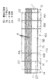
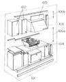
図に示すように、システムキッチン101を施工する際、ウオールキャビネット102を家屋の壁面に取り付けたのちにレンジフード103を取り付ける。レンジフード103の取り付けは、隣接するウオールキャビネット102の下端部に揃えて施工したり、レンジフードの下方に設置されるフロアキュビネット104よりの高さに合わせるようにして施工する。また、レンジフード103の天面の排気アダプター(図示せず)と室外と連通する排気ダクトを接続するための作業上、前記排気アダプター等を設置するスペースと作業スペースが必要である。
【0004】
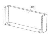
上記構成において、レンジフード103の天面と天井面の間に発生した隙間106bを塞ぐために別途レンジフード用幕板105を用意し、前記隙間106bを塞ぎ、レンジフード本体103にネジと金具によって共締めし、施工されていた。
【0005】
そして、上記のようにレンジフード103を施工した場合、家屋の床面から天井面までの距離の違い、あるいは隣接するウオールキャビネット102の下端部との揃えの関係、さらにフロアキャビネット104よりの法規による離隔距離106a等の関係で、レンジフード103の天面と天井面の隙間106bはまちまちとなり、これらの異なる隙間の寸法に合わせてレンジフード用幕板105を用意していた。
【0006】
また、レンジフード103の幅方向においても、サイズがまちまちで有るため、幅方向の隙間寸法に合わせたレンジフード用幕板105を用意していた。
【0007】
【発明が解決しようとする課題】
このような従来のレンジフード用幕板105では、レンジフード103の天面と天井面の隙間106bはまちまちで、隙間寸法に合わせて、レンジフード用幕板105を用意する必要が有るため、施工現場においては、レンジフード103を施工したあと、再度レンジフード用幕板105を取り付けにいったり、また、施工現場にレンジフード用幕板105を保管する場所がないため、散乱した施工現場では、落下し変形させたり、傷をつけたりするなど不良の原因になったり、レンジフード用幕板105を発注して納入されるまでの間、工事がストップしたりするため、工期が長期になったり、生産部門においては小ロット多品種生産になるため、コストアップになったり、在庫品として置いておく場所が必要となるなどの課題があった。
【0008】
このように、施工現場においては、高さ、幅調整が簡単に対応可能なレンジフード用幕板が要求されている。
【0009】
本発明は上記課題を解決するもので、施工現場において、幕板を平板より容易に加工することができ、保管場所および在庫経費の削減や品質改善を実現することのできるレンジフード用幕板を提供することを第1の目的とする。
【0010】
また、第2の目的は、レンジフ−ドの天面と天井面との隙間に容易に合わせることのできるレンジフード用幕板を提供することにある。
【0011】
また、第3の目的は、機種に幅の異なる複数のレンジフードに容易に使用できるレンジフード用幕板を提供することにある。
【0012】
【課題を解決するための手段】
本発明のレンジフード用幕板おいては、壁面に取り付けられたレンジフードの天面と室内の天井面の間に形成される隙間を閉鎖する平板状の幕板正面板と、この幕板正面板の少なくとも下方および左右側方に突出し形成される下方突出片および側方突出片とを備え、前記幕板正面板に対し、下方突出片および側方突出片を枠状に折り曲げ容易な連結部を介して連結する構成としたものである。
【0013】
この本発明によれば、施工現場においてレンジフードの天面と天井面との隙間を閉鎖する幕板を平板より容易に加工することができ、保管場所の確保、在庫経費の削減や品質改善を実現することのできるレンジフード用幕板を提供することができる。
【0014】
【発明の実施の形態】
本発明の請求項1に記載の発明は、フロアキャビネット、ウォールキャビネット、レンジフードよりなるシステムキッチンを設置する際、前記ウォールキャビネットの下端部に揃えて施工したり、前記レンジフードの下方に設置される前記フロアキャビネットよりの高さに合わせるように施工する前記レンジフードの天面と室内の天井面の間に形成される隙間を閉鎖するために折り曲げまたは切断により高さを前記隙間に合わせて前記レンジフードに取り付けるレンジフード用幕板であって、金属製平板状の幕板正面板と、この幕板正面板の少なくとも下方および左右側方に突出して形成され、枠状に折りまげ容易な連結部分とスリット部分を連続的に設けた連結部を介して連結される下方突出片および側方突出片と、前記幕板正面板と前記側方突出片の上下方向の複数段に折り曲げあるいは切断の容易な連結部分とスリット部分を連続的に設け形成される上下調節部とを備え、前記側方突出片の側方端部に上下方向に前記連結部を介して連結される補強片を設ける構成としたものであり、施工現場において、幕板正面板に対し、下方突出片および側方突出片を連結部により枠状に折り曲げ加工することによりレンジフード用幕板を形成することができるので、平板状態で保管や運搬が可能となり、保管や運搬が容易となり経費の節減が図れるという作用を有する。
【0015】
以下、本発明の実態の形態について、図1〜図6を参照しながら説明する。
(実施の形態1)
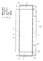
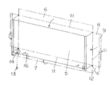
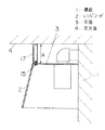
図1〜図3に示すように、壁面1に取り付けられたレンジフード2の天面3と室内の天井面4の間に形成される隙間Aを閉鎖する形状の幕板正面板5の上下に上方突出片6と下方突出片7を設け、左右側方に側方突出片8を設け、側方突出片8にはさらに補強片9を設け金属製の平板10を形成する。
【0016】
そして、平板10の上方突出片6と下方突出片7および、補強片9を設けた側方突出片8と幕板正面板5は連結部分とスリット部分を連続的に設けた折り曲げ容易な連結部11により連結し、補強片9も側方突出片8に連結部11を介して連結し、側方突出片8の下方には折り曲げ時に下方突出片7と重合する連結片12を連結部11を介して設け、連結片12と下方突出片7には、重合時にリベット13が挿通するリベット孔14を設け、下方突出片7にはレンジフード2の天面3にねじやナットよりなる取付手段15により取り付けるためのねじの係合溝16を設けた構成とする。
【0017】
上記構成において、レンジフード2の施工現場において壁面1に取り付けたレンジフード2の天面3と天井面4の間の隙間Aを閉鎖するときには、平板10の上方突出片6と下方突出片7および側方突出片8を各連結部11において幕板正面板5対し枠状となるように折り曲げ、補強片9も内側に折り曲げ、さらに側方突出片8に設けた連結片12と下方突出片7を重合し、リベット13で結合する。
【0018】
そして、枠状に形成された幕板17をレンジフード2の天面3と天井面4との隙間Aを閉鎖するように、レンジフード2の天面3上に係合溝16を利用し取付手段15により取り付ける。
【0019】
このように本発明の実施の形態1のレンジフード用幕板によれば、レンジフード2を取り付ける現場までは幕板17を平板10の状態で保管することができ、保管が容易となり保管場所を節減することができるとともに、運搬等も平板10の状態で運搬することができ、取り扱い容易となり、損傷も少なくなって品質向上を図ることができる。
【0020】
(実施の形態2)
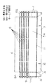
図4および図5に示すように、補強片9を含む側方突出片8Aおよび幕板正面板5Aの上下方向の複数段に折り曲げまたは切断が容易となるように連結部分とスリット部分を連続的に設けた上下調節部18を形成した構成とする。
【0021】
上記構成において、フロアキャビネット19、ウオールキャビネット20、レンジフード2等よりなるシステムキッチン21を設置した場合においては、フロアキャビネット19の高さを使用者の使用勝手を良くするため、例えばフロアキャビネット19の高さを高くしたときには、フロアキャビネット19とレンジフード2間を設定された離隔距離Bを維持するようにレンジフード2を設置した場合には、レンジフード2の天面3と天井面(図示せず)との間の隙間Aがせまくなり、一定の高さの幕板では使用できなくなる。このような場合には隙間Aの寸法にほぼ合致する高さに設けた上下調節部18により幕板17Aを折り曲げるかまたは切断することにより、幕板17Aの高さを隙間Aに合わせることができ、レンジフード2に取り付けて隙間Aを閉鎖することができる。
【0022】
このように本発明の実施の形態2のレンジフード用幕板によれば、レンジフード2の天面3と天井面との間の隙間Aの寸法が変わった場合においても、幕板17Aに設けた上下調節部18により容易に幕板17Aの高さ寸法を調節することができるので、その都度高さ寸法の異なる幕板を個別に用意する必要もなくなり、納期、工期の短縮が大幅に図れることとなる。
【0023】
(実施の形態3)
図6に示すように、機種によりレンジフード(図示せず)の横幅寸法が90cm、75cm、60cmと異なった複数の幅に形成されているレンジフードに対応できるように、幕板正面板5Bと上方突出片6Aおよび下方突出片7Aの左右方向の幅を90cmに形成し、その間に60cmの幅に対応する区切部22と75cm幅に対応する区切部23を連結部分とスリット部分を連続して形成し折り曲げあるいは切断容易に形成する。
【0024】
そして、下方突出片7Aには60cmあるいは75cmの幅のレンジフードに取り付けるための係合溝16Aと16Bを設け、区切部22あるいは区切部23で折り曲げ、下方突出片7A部分の区切部22あるいは23は切断し、下方突出片7Aを枠状に折り曲げたときに隣接する下方突出片7Aが重合する部分にレベット(図示せず)により結合できるリベット孔14Aを設ける。
【0025】
上記構成において、75cm幅のレンジフード対応する幕板を形成するときには、上方突出片6A、幕板正面板5B、下方突出片7Aを一体的に折り曲げ、上方突出片6Aと下方突出片7Aの区切部23は切断し、上方突出片6Aと下方突出片7Aを枠状に折り曲げ、リベット孔14Aを利用して重合する下方突出片7Aを結合し、75cm幅の幕板を形成する。
【0026】
また、60cm幅のレンジフードに対応する幕板を形成するときには、区切部22で折り曲げ、上記75cm幅の幕板を形成したときと同様の作業により60cm幅の幕板を形成することができる。
【0027】
このように本発明の実施の形態3のレンジフード用幕板によれば、1枚の幕板でレンジフードの幅の異なる3機種に対応することができるので、機種毎に幕板を作る必要がなく、また、施工現場においてもどの機種のレンジフードにも対応することができ、1種類の平板状の幕板を用意すればよいので幕板の保管管理も容易となるとともに同一形状の平板状の幕板を生産すれば良いので生産性も向上しコストも安くなることとなる。
【0028】
【発明の効果】
以上の実施の形態から明らかなように、本発明によれば平板状の幕板を施工現場において立体的な幕板に加工することができるので、平板状で保管ができ保管場所および在庫経費の削減や品質改善を実現することができるレンジフード用幕板を提供することができる。
【0029】
また、幕板の高さ調節を可能にしたので、レンジフードの天面と天井面との隙間に容易に合わせることができる。
【0030】
また、機種により幅の異なる種々のレンジフードに対応できるように平板状の幕板を形成したので、生産性が高く、コストの安いレンジフー用幕板を提供できる。
【図面の簡単な説明】
【図1】本発明の実施の形態1のレンジフード用幕板の平板時の状態を示す正面図
【図2】同レンジフード用幕板の平板を立体的に加工する状態を示す斜視図
【図3】同レンジフード用幕板を取り付けた状態を示す断面図
【図4】本発明の実施の形態2のレンジフード用幕板の平板時の状態を示す正面図
【図5】同レンジフード用幕板を使用したシステムキッチンの施工状態を示す斜視図
【図6】本発明の実施の形態3のレンジフード用幕板の平板時の状態を示す正面図
【図7】従来のレンジフード用幕板の斜視図
【図8】同レンジフード用幕板を使用したシステムキッチンの施工状態を示す斜視図
【符号の説明】
1 壁面
2 レンジフード
3 天面
4 天井面
5 幕板正面板
5A 幕板正面板
5B 幕板正面板
7 下方突出片
7A 下方突出片
8 側方突出片
8A 側方突出片
10 平板
11 連結部
18 上下調節部
22 区切部
23 区切部 [0001]
BACKGROUND OF THE INVENTION
The present invention relates to a range hood curtain plate that closes a gap between a top surface of a range hood that discharges oil smoke provided in a kitchen to the outside and a ceiling surface of the room.
[0002]
[Prior art]
Conventionally, this type of range hood curtain plate is generally shown in FIGS.
[0003]
Hereinafter, the configuration will be described with reference to FIGS.
As shown in the figure, when the system kitchen 101 is constructed, the range hood 103 is attached after the wall cabinet 102 is attached to the wall surface of the house. The range hood 103 is attached so as to be aligned with the lower end portion of the adjacent wall cabinet 102 or matched to the height of the floor cubine 104 installed below the range hood. Further, in order to connect an exhaust adapter (not shown) on the top surface of the range hood 103 to an exhaust duct communicating with the outside, a space for installing the exhaust adapter and the like are required.
[0004]
In the above configuration, a range hood curtain plate 105 is separately prepared to close the gap 106b generated between the top surface and the ceiling surface of the range hood 103, the gap 106b is closed, and the range hood main body 103 is shared by screws and metal fittings. It was tightened and constructed.
[0005]
And when the range hood 103 is constructed as described above, the difference in the distance from the floor surface to the ceiling surface of the house, or the relationship with the alignment with the lower end of the adjacent wall cabinet 102, and the regulations from the floor cabinet 104 The gap 106b between the top surface and the ceiling surface of the range hood 103 varies depending on the separation distance 106a and the like, and the curtain plate 105 for the range hood is prepared according to the size of these different gaps.
[0006]
In addition, since the sizes of the range hood 103 are also various, the range hood curtain plate 105 is prepared in accordance with the gap dimension in the width direction.
[0007]
[Problems to be solved by the invention]
In such a conventional range hood curtain plate 105, the gap 106b between the top surface and the ceiling surface of the range hood 103 varies, and it is necessary to prepare the range hood curtain plate 105 according to the gap dimension. At the site, after installing the range hood 103, the range hood curtain plate 105 is attached again, or there is no place to store the range hood curtain plate 105 at the construction site. It may cause defects such as falling and deforming, scratching, etc., or the construction will be stopped until the order and delivery of the curtain plate 105 for the range hood, so the construction period will be long, In the production department, small lots and many kinds of products are produced, and thus there are problems such as an increase in cost and a need for a place to store as inventory.
[0008]
Thus, on the construction site, there is a demand for a range hood curtain that can be easily adjusted in height and width.
[0009]
SUMMARY OF THE INVENTION The present invention solves the above-mentioned problems. A curtain plate for a range hood that can process a curtain plate more easily than a flat plate at a construction site, and can realize a reduction in storage space and inventory costs and quality improvement. The first purpose is to provide it.
[0010]
A second object is to provide a curtain plate for a range hood that can be easily adjusted to the gap between the top surface and the ceiling surface of the range hood.
[0011]
A third object is to provide a range hood curtain that can be easily used for a plurality of range hoods having different widths depending on the model.
[0012]
[Means for Solving the Problems]
In the range hood curtain plate of the present invention, a plate-like curtain plate front plate that closes a gap formed between the top surface of the range hood attached to the wall surface and the ceiling surface of the room, A connecting portion that includes a downward projecting piece and a lateral projecting piece that project at least downward and to the left and right sides of the face plate, and can be easily bent into a frame shape with respect to the front plate of the curtain plate. It is set as the structure connected through this.
[0013]
According to the present invention, the curtain plate that closes the gap between the top surface and the ceiling surface of the range hood at the construction site can be processed more easily than a flat plate, ensuring storage space, reducing inventory costs and improving quality. A curtain plate for a range hood that can be realized can be provided.
[0014]
DETAILED DESCRIPTION OF THE INVENTION
According to the first aspect of the present invention, when installing a system kitchen composed of a floor cabinet, a wall cabinet, and a range hood, the system kitchen is installed in alignment with the lower end of the wall cabinet or installed below the range hood. In order to close the gap formed between the top surface of the range hood and the ceiling surface of the room, which is constructed to match the height of the floor cabinet, the height is adjusted to the gap by bending or cutting. A range hood curtain plate to be attached to the range hood, which is formed of a metal flat curtain front plate and protruding at least downward and to the left and right sides of the front plate. A downwardly projecting piece and a laterally projecting piece connected through a connecting part provided with a portion and a slit part continuously, the curtain plate front plate and the And a vertical adjustment portion formed by continuously forming a slit portion and a connecting portion that can be easily bent or cut at a plurality of steps in the vertical direction of the side protruding piece, and at a side end portion of the side protruding piece in the vertical direction. It is configured to provide a reinforcing piece connected via the connecting portion , and at the construction site, the lower protruding piece and the side protruding piece are bent into a frame shape by the connecting portion with respect to the curtain plate front plate. Thus, the curtain plate for the range hood can be formed, so that it can be stored and transported in a flat state, and the storage and transport can be facilitated and the cost can be reduced.
[0015]
Hereinafter, the actual form of the present invention will be described with reference to FIGS.
(Embodiment 1)
As shown in FIGS. 1 to 3, the top and bottom of a curtain plate front plate 5 having a shape for closing a gap A formed between the top surface 3 of the range hood 2 attached to the wall surface 1 and the ceiling surface 4 in the room. An upper protruding piece 6 and a lower protruding piece 7 are provided, a side protruding piece 8 is provided on the left and right sides, and a reinforcing piece 9 is further provided on the side protruding piece 8 to form a metal flat plate 10.
[0016]
Then, the upper protruding piece 6 and the lower protruding piece 7 of the flat plate 10, the side protruding piece 8 provided with the reinforcing piece 9, and the curtain plate front plate 5 are a connecting part and an easily folding connecting part provided with a slit part continuously. 11, the reinforcing piece 9 is also connected to the side protruding piece 8 via the connecting portion 11, and a connecting piece 12 that overlaps with the lower protruding piece 7 when bent is provided below the side protruding piece 8. The connecting piece 12 and the downward projecting piece 7 are provided with a rivet hole 14 through which the rivet 13 is inserted during the polymerization, and the downward projecting piece 7 is provided with a mounting means 15 made of a screw or a nut on the top surface 3 of the range hood 2. In this configuration, an engagement groove 16 for a screw for mounting is provided.
[0017]
In the above configuration, when closing the gap A between the top surface 3 and the ceiling surface 4 of the range hood 2 attached to the wall surface 1 at the construction site of the range hood 2, the upper protruding piece 6 and the lower protruding piece 7 of the flat plate 10 and The side protruding pieces 8 are bent at each connecting portion 11 so as to form a frame shape with respect to the front plate 5 of the curtain plate, the reinforcing piece 9 is also bent inward, and the connecting pieces 12 provided on the side protruding pieces 8 and the downward protruding pieces 7 are also bent. Are polymerized and bonded with rivets 13.
[0018]
Then, the curtain plate 17 formed in a frame shape is mounted on the top surface 3 of the range hood 2 using the engagement grooves 16 so as to close the gap A between the top surface 3 and the ceiling surface 4 of the range hood 2. Attach by means 15.
[0019]
As described above, according to the curtain plate for the range hood of the first embodiment of the present invention, the curtain plate 17 can be stored in the state of the flat plate 10 until the site where the range hood 2 is installed, and the storage becomes easy. In addition to savings, transportation and the like can be carried in the state of the flat plate 10, making handling easier, reducing damage, and improving quality.
[0020]
(Embodiment 2)
As shown in FIGS. 4 and 5, the connecting portion and the slit portion are continuously provided so that the side protruding piece 8A including the reinforcing piece 9 and the curtain plate front plate 5A can be easily bent or cut in a plurality of steps in the vertical direction. It is set as the structure which formed the vertical adjustment part 18 provided in this.
[0021]
In the above configuration, when the system kitchen 21 including the floor cabinet 19, the wall cabinet 20, the range hood 2, etc. is installed, in order to improve the user's convenience in using the height of the floor cabinet 19, for example, When the range hood 2 is installed so as to maintain the set separation distance B between the floor cabinet 19 and the range hood 2 when the height is increased, the top surface 3 and the ceiling surface of the range hood 2 (not shown) The gap A between the first and second plates becomes so large that it cannot be used with a curtain plate of a certain height. In such a case, the height of the curtain plate 17A can be adjusted to the gap A by bending or cutting the curtain plate 17A by the vertical adjustment portion 18 provided at a height substantially matching the size of the gap A. The gap A can be closed by being attached to the range hood 2.
[0022]
Thus, according to the range hood curtain plate of the second embodiment of the present invention, even when the dimension of the gap A between the top surface 3 and the ceiling surface of the range hood 2 changes, it is provided on the curtain plate 17A. Since the height of the curtain plate 17A can be easily adjusted by the vertical adjustment unit 18, it is not necessary to prepare a curtain plate having a different height each time, and the delivery time and construction period can be greatly shortened. It will be.
[0023]
(Embodiment 3)
As shown in FIG. 6, the curtain front plate 5 </ b> B and the range hood (not shown) can be adapted to range hoods having a width different from 90 cm, 75 cm, and 60 cm depending on the model. The upper projecting piece 6A and the lower projecting piece 7A are formed with a width of 90 cm in the left-right direction. Form and bend or cut easily.
[0024]
Then, the downward projecting piece 7A provided engaging grooves 16A and 16B for mounting the hood width of 60cm or 75 cm, bent at separated portions 22 or the separator unit 23, the lower protruding piece 7A portion of the separator unit 22 or 23 Is cut, and a rivet hole 14A that can be connected by a rivet (not shown) is provided at a portion where the adjacent lower protruding piece 7A overlaps when the lower protruding piece 7A is bent into a frame shape.
[0025]
In the above configuration, when a curtain plate corresponding to a 75 cm wide hood is formed, the upper projecting piece 6A, the curtain plate front plate 5B, and the lower projecting piece 7A are integrally bent to separate the upper projecting piece 6A and the lower projecting piece 7A. The portion 23 is cut, the upper projecting piece 6A and the lower projecting piece 7A are bent into a frame shape, and the lower projecting piece 7A that is superposed using the rivet holes 14A is joined to form a 75 cm wide curtain.
[0026]
Further, when a curtain plate corresponding to a 60 cm wide range hood is formed, the curtain plate having a 60 cm width can be formed by the same operation as when the curtain plate having the 75 cm width is formed by bending at the partitioning portion 22.
[0027]
As described above, according to the range hood curtain plate of the third embodiment of the present invention, it is possible to deal with three types of range hoods having different widths with a single curtain plate, so it is necessary to make a curtain plate for each model. In addition, it can be applied to any type of range hood at the construction site, and it is only necessary to prepare one type of flat plate so that the storage management of the plate is easy and the flat plate of the same shape is used. It is sufficient to produce a curtain-like screen, which increases productivity and reduces costs.
[0028]
【The invention's effect】
As is clear from the above embodiment, according to the present invention, a flat curtain plate can be processed into a three-dimensional curtain plate at the construction site. It is possible to provide a range hood curtain that can achieve reduction and quality improvement.
[0029]
In addition, since the height of the curtain can be adjusted, it can be easily adjusted to the gap between the top surface and the ceiling surface of the range hood.
[0030]
Further, since the flat curtain plate is formed so as to be compatible with various range hoods having different widths depending on the model, it is possible to provide a range hood curtain plate with high productivity and low cost.
[Brief description of the drawings]
FIG. 1 is a front view showing a state of a flat plate of a range hood curtain plate according to Embodiment 1 of the present invention. FIG. 2 is a perspective view showing a state in which the flat plate of the range hood curtain plate is three-dimensionally processed. FIG. 3 is a cross-sectional view showing a state in which the curtain plate for the range hood is attached. FIG. 4 is a front view showing a state when the curtain plate for the range hood according to the second embodiment of the present invention is flat. FIG. 6 is a perspective view showing a construction state of a system kitchen using a curtain plate. FIG. 6 is a front view showing a flat plate state of a curtain plate for a range hood according to Embodiment 3 of the present invention. Perspective view of the curtain [Figure 8] Perspective view showing the construction state of the system kitchen using the same range hood curtain [Explanation of symbols]
DESCRIPTION OF SYMBOLS 1 Wall surface 2 Range hood 3 Top surface 4 Ceiling surface 5 Curtain plate front plate 5A Curtain plate front plate 5B Curtain plate front plate 7 Lower protrusion piece 7A Lower protrusion piece 8 Side protrusion piece 8A Side protrusion piece 10 Flat plate 11 Connection part 18 Vertical adjustment part 22 division part 23 division part