JP3607060B2 - Airborne bacteria collector and nozzle windshield - Google Patents
Airborne bacteria collector and nozzle windshield Download PDFInfo
- Publication number
- JP3607060B2 JP3607060B2 JP26091897A JP26091897A JP3607060B2 JP 3607060 B2 JP3607060 B2 JP 3607060B2 JP 26091897 A JP26091897 A JP 26091897A JP 26091897 A JP26091897 A JP 26091897A JP 3607060 B2 JP3607060 B2 JP 3607060B2
- Authority
- JP
- Japan
- Prior art keywords
- nozzle
- windshield
- chamber
- petri dish
- openings
- Prior art date
- Legal status (The legal status is an assumption and is not a legal conclusion. Google has not performed a legal analysis and makes no representation as to the accuracy of the status listed.)
- Expired - Fee Related
Links
- 241000894006 Bacteria Species 0.000 title claims description 24
- 238000002347 injection Methods 0.000 claims description 10
- 239000007924 injection Substances 0.000 claims description 10
- 239000002609 medium Substances 0.000 description 39
- 239000007788 liquid Substances 0.000 description 29
- 241000233866 Fungi Species 0.000 description 26
- 229920001817 Agar Polymers 0.000 description 17
- 239000008272 agar Substances 0.000 description 17
- 239000011521 glass Substances 0.000 description 12
- 229910001220 stainless steel Inorganic materials 0.000 description 9
- 239000010935 stainless steel Substances 0.000 description 9
- XLYOFNOQVPJJNP-UHFFFAOYSA-N water Chemical compound O XLYOFNOQVPJJNP-UHFFFAOYSA-N 0.000 description 8
- 238000010586 diagram Methods 0.000 description 5
- 230000002093 peripheral effect Effects 0.000 description 5
- 239000007921 spray Substances 0.000 description 5
- 238000005507 spraying Methods 0.000 description 5
- 239000012153 distilled water Substances 0.000 description 3
- 230000000694 effects Effects 0.000 description 3
- 239000002184 metal Substances 0.000 description 3
- 238000005406 washing Methods 0.000 description 3
- 238000004140 cleaning Methods 0.000 description 2
- 239000001963 growth medium Substances 0.000 description 2
- 238000013022 venting Methods 0.000 description 2
- LFQSCWFLJHTTHZ-UHFFFAOYSA-N Ethanol Chemical compound CCO LFQSCWFLJHTTHZ-UHFFFAOYSA-N 0.000 description 1
- 238000007664 blowing Methods 0.000 description 1
- 230000008094 contradictory effect Effects 0.000 description 1
- 238000007796 conventional method Methods 0.000 description 1
- 238000005553 drilling Methods 0.000 description 1
- 239000004744 fabric Substances 0.000 description 1
- 238000001914 filtration Methods 0.000 description 1
- 239000012530 fluid Substances 0.000 description 1
- 239000000463 material Substances 0.000 description 1
- 238000005259 measurement Methods 0.000 description 1
- 238000000034 method Methods 0.000 description 1
- 238000012545 processing Methods 0.000 description 1
Images


Classifications
-
- C—CHEMISTRY; METALLURGY
- C12—BIOCHEMISTRY; BEER; SPIRITS; WINE; VINEGAR; MICROBIOLOGY; ENZYMOLOGY; MUTATION OR GENETIC ENGINEERING
- C12M—APPARATUS FOR ENZYMOLOGY OR MICROBIOLOGY; APPARATUS FOR CULTURING MICROORGANISMS FOR PRODUCING BIOMASS, FOR GROWING CELLS OR FOR OBTAINING FERMENTATION OR METABOLIC PRODUCTS, i.e. BIOREACTORS OR FERMENTERS
- C12M33/00—Means for introduction, transport, positioning, extraction, harvesting, peeling or sampling of biological material in or from the apparatus
- C12M33/04—Means for introduction, transport, positioning, extraction, harvesting, peeling or sampling of biological material in or from the apparatus by injection or suction, e.g. using pipettes, syringes, needles
-
- C—CHEMISTRY; METALLURGY
- C12—BIOCHEMISTRY; BEER; SPIRITS; WINE; VINEGAR; MICROBIOLOGY; ENZYMOLOGY; MUTATION OR GENETIC ENGINEERING
- C12M—APPARATUS FOR ENZYMOLOGY OR MICROBIOLOGY; APPARATUS FOR CULTURING MICROORGANISMS FOR PRODUCING BIOMASS, FOR GROWING CELLS OR FOR OBTAINING FERMENTATION OR METABOLIC PRODUCTS, i.e. BIOREACTORS OR FERMENTERS
- C12M41/00—Means for regulation, monitoring, measurement or control, e.g. flow regulation
- C12M41/40—Means for regulation, monitoring, measurement or control, e.g. flow regulation of pressure
-
- C—CHEMISTRY; METALLURGY
- C12—BIOCHEMISTRY; BEER; SPIRITS; WINE; VINEGAR; MICROBIOLOGY; ENZYMOLOGY; MUTATION OR GENETIC ENGINEERING
- C12M—APPARATUS FOR ENZYMOLOGY OR MICROBIOLOGY; APPARATUS FOR CULTURING MICROORGANISMS FOR PRODUCING BIOMASS, FOR GROWING CELLS OR FOR OBTAINING FERMENTATION OR METABOLIC PRODUCTS, i.e. BIOREACTORS OR FERMENTERS
- C12M23/00—Constructional details, e.g. recesses, hinges
- C12M23/02—Form or structure of the vessel
- C12M23/10—Petri dish
Landscapes
- Chemical & Material Sciences (AREA)
- Health & Medical Sciences (AREA)
- Life Sciences & Earth Sciences (AREA)
- Organic Chemistry (AREA)
- Engineering & Computer Science (AREA)
- Bioinformatics & Cheminformatics (AREA)
- Zoology (AREA)
- Wood Science & Technology (AREA)
- Microbiology (AREA)
- Sustainable Development (AREA)
- Biotechnology (AREA)
- Biomedical Technology (AREA)
- Biochemistry (AREA)
- General Engineering & Computer Science (AREA)
- General Health & Medical Sciences (AREA)
- Genetics & Genomics (AREA)
- Analytical Chemistry (AREA)
- Molecular Biology (AREA)
- Apparatus Associated With Microorganisms And Enzymes (AREA)
Description
【0001】
【発明の属する技術分野】
本発明は、空気中に浮遊する菌類を液体培地に捕集するための浮遊菌捕集装置に関するものであり、及び該浮遊菌捕集装置のノズルに取り付けるための風防に関するものである。
【0002】
【従来の技術】
従来、寒天培地内に菌類を植え付ける装置としては、寒天培地の穿孔手段と該穿孔手段によって開口された溝に菌類を塗布する手段とを組み合わせて成るものや、注射針を用いて直接寒天培地に植え付ける構成のものなどが存在していた。しかしながら前者では寒天培地への穿孔作業と菌類の塗布作業との2種類の作業を順に行なわなければならなかった。また両者共に寒天培地へ菌類を植え付けるためには、穿孔手段や塗布手段や注射針等の植付手段を何度も上げ下げしなくてはならず作業が非能率的であった。望ましくは植付手段が寒天培地に触れることなくしかも寒天培地の深部へ菌類を植え付け得るものでありたい。この一見矛盾した要求を満足させるために寒天培地に対して菌類を吹き付ける手段を採用することが考えられる。吹きつけ方式であれば寒天培地に触れることなくその深部へ菌類を植え付けることが出来るから効率的である。
【0003】
この構成例としては、図12で表されるような寒天培地8を入れたシャーレ9を載置するための受皿を駆動装置により回転可能にチャンバー内に設け、チャンバー内を負圧にするための真空ポンプをチャンバーの抜気口に接続し、、チャンバーに外気の吸入口を設けると共に、吸入口から吸入した外気をシャーレの寒天培地に向けて噴射するためのノズルをチャンバー内に取り付けた浮遊菌捕集装置を上げることが出来る。
【0004】
さて上記は寒天培地に浮遊菌を植え付けるタイプの捕集装置であり、このままこの寒天培地上で培養する場合もあれば、菌を植え付けられた寒天をスポイト等で採り、これを洗浄し、その液体をATPに入れるという作業を行なう場合もある。後者の場合、作業はとても手間が掛かるものであった。他方で蒸留水や特殊洗浄水に直接菌類を塗布するタイプがあるが、この方式を浮遊菌捕集装置に適用出来れば、短時間で浮遊菌をATPに捕集して供給することが可能と成る。そもそも浮遊菌を捕集する目的は、事務所等の一般的な環境やクリーンルームに於ける主として空気中の浮遊菌を計数することにある。
【0005】
【発明が解決しようとする課題】
上述したようにATPに浮遊菌を吹き付けて直接捕集することが可能であればこれが最も能率が良いのであるが、寒天培地の深部へ浮遊菌を植え付け得るだけの吹付力をそのまま利用したのでは、寒天の場合と異なり液体状のATPが飛散するという新たな問題を生ずる。即ち空気中の浮遊菌を捕集するためにはそれなりの吸引力を必要とするがこれをそのままATPに向けることは出来ない。またチャンバーに毎分60リットルの減圧を設定し、ピンホール状のノズル直径φを0.8ミリメートルとして上記減圧を行なうと、時によっては出口毎秒約100メートルの噴射初期速度が得られる場合もあり、浮遊菌が液面に衝突して死んでしまうことが観察されている。何れにせよATPを飛散させてしまっては具合が悪いのである。
【0006】
そこで本発明はこのような問題を解決し、液体状のATP(液体培地)を飛散させることなくそのまま浮遊菌を吹き付けることが出来るような浮遊菌捕集装置及びノズルの風防を提供する。
【0007】
【課題を解決するための手段】
上記課題は、シャーレを載置するための受皿を、駆動装置により回転可能にチャンバー内に設け、チャンバー内を負圧にするための真空ポンプをチャンバーの抜気口に接続し、チャンバーに外気の吸入口を設けると共に、吸入口から吸入した外気をシャーレに向けて噴射するためのノズルをチャンバー内に取り付け、該ノズルに噴射方向に対し略直角方向に風を逃がすための開口部を備えた風防を取り付けて成る浮遊菌捕集装置とすることにより達成される。
【0008】
また請求項2の発明は、請求項1に関して前記ノズルが受皿に対して複数箇所設けられていることを特徴とするものとした。
【0009】
また請求項3の発明は、請求項1に関して前記ノズルがピンホールの配列から構成されていることを特徴とするものとした。
【0010】
また請求項4の発明は、請求項1に関して前記風防がノズルに対して着脱自在に設けられていることを特徴とするものとした。
【0011】
また上記課題は、請求項5の発明、即ち浮遊菌捕集装置のノズルに取り付ける風防であって、ノズルの噴射方向に対して略直角方向に風を逃がすための開口部を備えて成るノズルの風防とすることにより達成される。
【0012】
また請求項6の発明は、請求項5に関して開口部が複数箇所形成されていることを特徴とするものとした。
【0013】
また請求項7の発明は、請求項5に関して風防の先端部が先細り形状を呈するものであることを特徴とするものとした。
【0014】
【作用】
本浮遊菌捕集装置によれば、真空ポンプを作動させるとチャンバーの抜気口からチャンバー内の空気が吸い出されてチャンバー内は負圧と成る。すると吸入口から外気が吸い込まれてノズルからシャーレに向けて勢いよく噴射される。この時前記ノズルに噴射方向に対し略直角方向に風を逃がすための開口部を備えた風防が取り付けられていることにより、開口部が高過ぎる圧力を抜き適度な空気流を前記シャーレに向けて吹き付ける。この結果シャーレ内の液体培地を飛散させることなく外気に含まれる菌類を液体培地に捕集させることが出来る。また駆動装置は受皿上のシャーレを回転させるので、外気に含まれる菌類が培地全体に均一に吹き付けられることに成る。尚、風を逃がす方向を略直角方向としているが、前記シャーレに向けて吹き付ける本流から逸らすことが出来ればこの角度が略直角方向である、ということにしたことによる。
【0015】
また請求項2の発明では、前記ノズルが受皿に対し複数箇所設けられているため、より少ない時間で受皿上のシャーレ内の液体培地全体に行き渡らせることが出来る。尚、ノズルの形状の選択は任意事項であるが、例えばシャーレの径方向に細長く、且つ、シャーレの半径分の長さを有する形状とした場合、受皿を1回転させたところでちょうど液体培地の全体に菌類を行き渡らせることが出来る。而して、このような形状のノズルを受皿の回転に対して2回対称に配置すれば、受皿を半回転させるだけで液体培地の全体に菌類を行き渡らせることが可能であるし(勿論ノズルをシャーレの直径分に相当する長さを有する形状とした場合受皿を半回転させるだけで液体培地の全体に菌類を行き渡らせることが出来る)、ノズルを3回対称に配置すれば、受皿を1/3回転させるだけでよいということに成る。
【0016】
また請求項3の発明では、前記ノズルがピンホールの配列から構成されているため、各々のピンホールが一定の吹き付け範囲をカバーし、ピンホール全体でノズルの吹き付け範囲をカバーすることに成る。尚、シャーレ内の円周長は中心ほど小さいのであるから、均等に吹き付けるためにピンホールはその間の距離がシャーレの中心に向かうほど大きく成るように整列配置されることがより望ましい。
【0017】
また請求項4の発明では、前記風防がノズルに対して着脱自在に設けられているため、風防を外した場合には上述した寒天培地に浮遊菌を植え付けるタイプの捕集装置として使用可能と成る。
【0018】
次に請求項5の発明、即ちノズルの噴射方向に対して略直角方向に風を逃がすための開口部を備えて成る風防では、浮遊菌捕集装置のノズルに当該風防を取り付けることにより、開口部が高過ぎる圧力を抜き適度な空気流を前記シャーレに向けて吹き付ける。この結果シャーレ内の液体培地を飛散させることなく外気に含まれる菌類を液体培地に捕集させることが出来る。尚、本発明の風防は上述した寒天培地に浮遊菌を植え付けるタイプの捕集装置にも取り付け得るように構成することが可能である。
【0019】
また請求項6の発明は、請求項5の発明に付いて開口部が複数箇所形成されているものであるため、開口部が高過ぎる圧力を抜く際にただ一方向にだけではなく複数方向に抜くことが出来、菌類を液体培地に略均等な圧力で吹き付けることが可能となる。
【0020】
また請求項7の発明は、請求項5の発明に付いて風防の先端部が先細り形状を呈するものであるため、開口部で高過ぎる圧力を抜いた後、菌類を含んだ空気流を液体培地に集中させることが出来る。
【0021】
【実施例】
次に本発明の幾つかの実施例を図面を参照しながら説明するが、本発明はこれ等の実施例にのみ限定されるものではない。尚、請求項の記載順ではなく風防の発明の方から先に実施例を上げて説明して行く。
【0022】
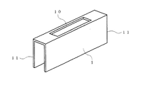
図1は本発明の風防を表わす第1実施例の斜視図である。縦断面がコ字形状を呈する風防1は、吹き付け方向が開口されていると共にその両側が開口部11,11にて開口された状態にある。また上面部にはノズルに装着するための装着口10が開口されている。
【0023】
本実施例の風防は、装着口10を以てノズルに装着して使用する。ノズルから噴射された空気流はその高過ぎる圧力が両側の開口部11,11で抜かれ、適度な空気流がシャーレに向けて吹き付けられる。この結果シャーレ内の液体培地を飛散させることなく外気に含まれる菌類を液体培地に捕集させることが出来る。
【0024】
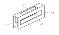
次に図2は本発明の風防を表す第2実施例の斜視図であるが、第1実施例の開口部11,11に加えこれと略直角方向の壁面にも開口部15,15を開口して成る。
【0025】
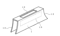
次に図3は本発明の風防を表す第3実施例の斜視図であるが、第1実施例の開口部の形状を変え、開口部間の距離が末広がりと成るような開口部12,12を開口して成る。更に鎖線で示すように開口部12,12と略直角方向の壁面に開口部15,15を開口してもよい。前記開口部12,12の形状は実際の空気の流れを研究した成果である。
【0026】
次に図4は本発明の風防を表す第4実施例の側面図であるが、第2実施例の構成に加え風防の先端部が先細り形状を呈するような先端部13を形成して成るものである。開口部11,11で高過ぎる圧力を抜いた後、菌類を含んだ空気流を先端部13によって液体培地に集中させることが出来る。
【0027】
次に図5は本発明の風防の第5実施例の使用状態説明図である。図6はこの時風防1が取り付けられる、外気の吸入口である吸入ダクト2の底面図であるが、吸入ダクト2の底部のノズル20には噴射口である7個のピンホール21がその間の距離がシャーレの中心に向かうほど大きく成るように整列配置されている。シャーレ内の円周長は中心ほど小さいので、菌類を含んだ空気流をシャーレに均等に吹き付けるための構成である。当該吸入ダクト2の底部に本実施例の風防1が取り付けられている。傾斜した開口部14,14により風防1は台形を呈しており、これと略直角方向の壁面にも開口部15,15が開口されて成る。
【0028】
前記吸入ダクト2のノズル20のピンホール21から噴射された空気流はその高過ぎる圧力が両側の開口部14,14及びこれと略直角方向の壁面にある開口部15,15で矢線のように抜かれ、適度な空気流がシャーレに向けて吹き付けられる。この結果シャーレ内の液体培地を飛散させることなく外気に含まれる菌類を液体培地に捕集させることが出来る。
【0029】
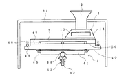
さて図7及び図8は、上述した風防1をダクト2に備えた本発明の浮遊菌捕集装置3の説明図である。これを便宜上第6実施例とする。アルコール等で殺菌処理を施してある表面に蒸留水と洗浄水とを付着させたシャーレとしてのガラス皿5を載置するためのターンテーブル40は、キャップ31によって気密が保たれるチャンバー30内に設けられており、ターンテーブル40は駆動装置を構成するステッピングモータ33によって回転可能である。チャンバー30内を負圧にするための真空ポンプ34の吸気側とチャンバー30とはパイプ35で連結され、また真空ポンプ34の排気側は別のパイプ35を介して捕集装置3の外部へ導かれている。符号36はドライバ回路、符号37はスイッチング電源回路であり、真空ポンプ34や回転装置4のターンテーブル40等を駆動し、符号39はこれ等のON/OFFのためのスイッチである。手動つまみ38と回転装置4のターンテーブル40の回転軸42との間には図示していないベルトが架け渡されており、手動つまみ38はモータ33を使用することなくターンテーブル40を回転させる際に利用するものである。尚、符号32はチャンバー30のキャップ31を開閉するための回動軸である。
【0030】
図8から明らかと成るように、前記回転軸42と受け41との間にはボール44が挿着されており、該ボール44は回転軸42周りに設けたバネ43により上方に付勢されて受け41を押し上げるように働く。円盤状の受け41の上面外周部にはボール48が回転自在に取り付けられており、該ボール48を介してターンテーブル40を押し上げている。他方当該ターンテーブル40の上面外周部にもボール45が回転自在に取り付けられており、該ボール45はまたバネ46により上方から下方に向けて付勢され、前記バネ43との間で均衡を保つように調整されている。ボール45はターンテーブル40の上面外周部の3回対称の位置に設けられているが、これは4回対称の位置等としてもよい。このターンテーブル40上に上述したガラス皿5が載置されることに成るが、当該ガラス皿5の下面外周部には溝50が刻設されており、該溝50に前記ターンテーブル40の上面外周部に突設したキー47が掛合し得るように構成されている。
【0031】
また吸入ダクト2はその上端部が外部へ取り出されるようにして前記開閉自在のキャップ31に取り付けられている。吸入ダクト2の底部には本発明の風防1が取り付けられている。該風防1は傾斜した開口部14,14により台形を呈しており、これと略直角方向の壁面にも開口部15,15が開口されている。吸入ダクト2と風防1とは図5及び図6で表されたものと同一である。
【0032】
そこで真空ポンプ34を駆動するとチャンバー30内は負圧と成り、前記吸入ダクト2から菌類を含んだ外気が勢いよく吸入されるが、外気は吸入ダクト2の底部にあるピンホール21から下方に向けて噴出される。この際の空気流は風防1に於いてその高過ぎる圧力が両側の開口部14,14及びこれと略直角方向の壁面にある開口部15,15で抜かれ、適度な空気流がガラス皿5の表面に向けて吹き付けられる。当該ガラス皿5の表面には蒸留水と洗浄水とが付着しているが、この液体培地を飛散させることなく外気に含まれる菌類が液体培地に捕集される。この時ターンテーブル40の回転に伴ってガラス皿5も回転しており、前記ピンホール21の列はガラス皿5の半径分の範囲をカバーしており、ガラス皿5を1回転させたところでちょうど液体培地全体に菌類を行き渡らせることが出来るわけである。尚、チャンバー30を通過した空気流はパイプ35を経由して真空ポンプ34に至り、更に別のパイプ35を経由して捕集装置3の外へ排気される。この際、浮遊菌捕集装置3の排気口に浮遊菌を濾過し得るフイルターを設けることも出来る。
【0033】
次に図9は本発明の浮遊菌捕集装置3の説明図であり、これを便宜上第7実施例とする。本実施例の特徴は第6実施例の構成に於いてガラス皿5の半径分の範囲をカバーする吸入ダクト2が、ガラス皿5の回転に対して2回対称の位置に配置されている点にある。これによってガラス皿5を半回転させるだけで液体培地の全体に菌類を行き渡らせることが可能と成っている。尚、更に3回対称、4回対称の位置に配置する構成も可能であり、浮遊菌捕集に掛かる時間が短縮される効果がある。
【0034】
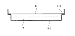
さて図10は前記ガラス皿5の代わりに用いることが出来るシャーレとしてのステンレス皿51を平面図で表したものである。当該ステンレス皿51は水溜の部分とその周囲の縁部とから構成されており、縁部には上方へ引き出し自在な取手52が2回対称の位置に設けられている。取手52は縁部の孔53に挿入されて止められている。水溜の部分には液体培地が溜められる。
【0035】
次に図11は上記ステンレス皿51の別形態を表し、ステンレス皿51には金属メッシュや布のフイルター6が取り付けられ、特殊洗浄液7の飛散を防止するように成っている。当該フイルター6の周囲には縁金具60が取り付けられておりステンレス皿51に自重で止まるように成っている。尚、ステンレス皿51にパッチン錠を設けて縁金具60の部位を止めるようにする構成も可能である。
【0036】
尚、本発明はこれ等の実施例にのみ限定されないから、例えば培地表面とノズルとの間の距離を計測する手段を設けたり、この計測の結果に基づいて培地表面とノズルとの間の距離を微調整する手段を取り付けることも出来る。受皿を回転させる駆動装置の種類も従来からの各種技術が利用可能であるから特に限定されない。シャーレに向けて噴射するためのノズルの形状も自由である。制御装置のマンマシンインターフェイス部の構成も任意である。また風防の全体形状や開口部の形状、風防の素材等の選択も任意事項である。
【0037】
【発明の効果】
以上本発明は、シャーレを載置するための受皿を、駆動装置によって回転可能にチャンバー内に設け、チャンバー内を負圧にするための真空ポンプをチャンバーの抜気口に接続し、チャンバーに外気の吸入口を設けると共に、吸入口から吸入した外気をシャーレに向けて噴射するためのノズルをチャンバー内に取り付け、ノズルに噴射方向に対し略直角方向に風を逃がすための開口部を備えた風防を取り付けて成る浮遊菌捕集装置とした。また浮遊菌捕集装置のノズルに取り付ける風防に付いて本発明では、ノズルの噴射方向に対して略直角方向に風を逃がすための開口部を備えて成るものとした。
【0038】
この結果、液体状のATP(液体培地)を飛散させることなくそのまま浮遊菌を吹き付けることが出来るように成り、全体の処理が能率的に成るなどの効果を獲得している。
【図面の簡単な説明】
【図1】本発明の第1実施例の斜視図である。
【図2】本発明の第2実施例の斜視図である。
【図3】本発明の第3実施例の斜視図である。
【図4】本発明の第4実施例の側面図である。
【図5】本発明の第5実施例の使用状態説明図である。
【図6】吸入ダクトの底面図である。
【図7】本発明の第6実施例の説明図である。
【図8】同実施例の回転装置部分の説明図である。
【図9】本発明の第7実施例の説明図である。
【図10】同実施例に使用するステンレス皿の平面図である。
【図11】同実施例に使用するステンレス皿の平面図である。
【図12】従来例に於ける培養容器の説明図である。
【符号の説明】
1 風防
10 装着口
11 開口部
12 開口部
13 先端部
14 開口部
15 開口部
2 吸入ダクト
20 ノズル
21 ピンホール
3 捕集装置
30 チャンバー
31 キャップ
32 回動軸
33 モータ
34 真空ポンプ
35 パイプ
36 ドライバ回路
37 電源回路
38 手動つまみ
39 スイッチ
4 回転装置
40 ターンテーブル
41 受け
42 回転軸
43 バネ
44 ボール
45 ボール
46 バネ
47 キー
48 ボール
5 ガラス皿
50 溝
51 ステンレス皿
52 取手
53 孔
6 フイルター
60 縁金具
7 洗浄液[0001]
BACKGROUND OF THE INVENTION
The present invention relates to a floating bacteria collecting apparatus for collecting fungi floating in the air in a liquid medium, and to a windshield for attaching to a nozzle of the floating bacteria collecting apparatus.
[0002]
[Prior art]
Conventionally, as a device for inoculating fungi in an agar medium, a combination of an agar medium perforation means and a means for applying fungi to a groove opened by the perforation means, or an agar medium directly using an injection needle There were things that were planted. However, in the former, it was necessary to sequentially perform two types of operations, a drilling operation on an agar medium and a fungus application operation. In both cases, in order to inoculate fungi on the agar medium, the perforation means, the application means, the injection means such as the injection needle must be raised and lowered many times, and the work is inefficient. Desirably, the planting means should be capable of planting fungi deep in the agar medium without touching the agar medium. In order to satisfy this seemingly contradictory requirement, it is conceivable to employ means for spraying fungi on the agar medium. The spraying method is efficient because it can plant fungi deeply without touching the agar medium.
[0003]
As an example of this configuration, a tray for placing a
[0004]
The above is a type of collection device in which floating bacteria are planted on an agar medium. In some cases, the culture is carried out on this agar medium, or the agar planted with the bacteria is taken with a dropper, washed, and the liquid There is also a case where an operation of putting A into ATP is performed. In the latter case, the work was very time-consuming. On the other hand, there is a type that applies fungi directly to distilled water or special washing water, but if this method can be applied to floating bacteria collection device, it is possible to collect and supply floating bacteria to ATP in a short time. Become. In the first place, the purpose of collecting floating bacteria is to mainly count floating bacteria in the air in a general environment such as an office or a clean room.
[0005]
[Problems to be solved by the invention]
As mentioned above, this is the most efficient if it is possible to spray ATP on ATP and collect it directly. Unlike the case of agar, there is a new problem that liquid ATP is scattered. That is, in order to collect airborne bacteria in the air, a certain suction force is required, but this cannot be directly directed to ATP. In addition, if a vacuum of 60 liters per minute is set in the chamber and the pressure is reduced by setting the pinhole-shaped nozzle diameter φ to 0.8 millimeters, an initial injection speed of about 100 meters per second may be obtained in some cases. It has been observed that airborne microbes collide with the liquid surface and die. In any case, if ATP is scattered, it is bad.
[0006]
Therefore, the present invention solves such problems and provides a floating bacteria collecting apparatus and a windshield for a nozzle that can spray floating bacteria as they are without scattering liquid ATP (liquid medium).
[0007]
[Means for Solving the Problems]
The above problem is that a tray for placing the petri dish is rotatably provided in the chamber by a driving device, a vacuum pump for making the inside of the chamber a negative pressure is connected to the venting port of the chamber, an inlet provided with a nozzle for injecting toward the outside air sucked from the suction port into a petri dish mounted in the chamber, with openings for releasing air in the direction substantially perpendicular to the injection direction to the nozzle windshield This is achieved by providing an airborne bacteria collecting device to which is attached.
[0008]
The invention of
[0009]
According to a third aspect of the present invention, the nozzle according to the first aspect is constituted by an array of pinholes.
[0010]
According to a fourth aspect of the present invention, the windshield according to the first aspect is provided detachably with respect to the nozzle.
[0011]
The above-mentioned subject is the windshield attached to the nozzle of the invention of
[0012]
The invention of
[0013]
The invention of
[0014]
[Action]
According to this airborne microbe collection apparatus, when the vacuum pump is operated, air in the chamber is sucked out from the venting port of the chamber, and the chamber has a negative pressure. Then, outside air is sucked from the suction port and is jetted vigorously from the nozzle toward the petri dish . By being windshield with openings is attached for releasing the air at this time substantially perpendicular direction to the injection direction to the nozzle, a moderate air flow the pressure is removed the opening is too high toward the dish Spray. As a result, fungi contained in the outside air can be collected in the liquid medium without scattering the liquid medium in the petri dish . Moreover, since the drive device rotates the petri dish on the saucer , fungi contained in the outside air are sprayed uniformly over the entire culture medium. In addition, although the direction which escapes a wind is made into the substantially right angle direction, if it can deviate from the main stream sprayed toward the said petri dish , it is because this angle is set to a substantially right angle direction.
[0015]
In the invention of
[0016]
In the invention of
[0017]
In the invention of
[0018]
Next, in the invention of
[0019]
The invention of
[0020]
Further, since the tip of the windshield has a tapered shape in accordance with the invention of
[0021]
【Example】
Next, some embodiments of the present invention will be described with reference to the drawings, but the present invention is not limited to these embodiments. It should be noted that the embodiment will be described first from the direction of the invention of the windshield, not in the order of claims.
[0022]
FIG. 1 is a perspective view of a first embodiment showing a windshield of the present invention. The
[0023]
The windshield of this embodiment is used by being attached to the nozzle with the
[0024]
Next, FIG. 2 is a perspective view of the second embodiment showing the windshield of the present invention. In addition to the openings 11 and 11 of the first embodiment, the openings 15 and 15 are also opened on the wall surface in a direction substantially perpendicular thereto. It consists of
[0025]
Next, FIG. 3 is a perspective view of the third embodiment showing the windshield of the present invention. The openings 12, 12 are formed such that the shape of the opening of the first embodiment is changed and the distance between the openings becomes wider. Opened. Further, as indicated by a chain line, the openings 15 and 15 may be opened on the wall surface in a direction substantially perpendicular to the openings 12 and 12. The shape of the openings 12 and 12 is a result of studying actual air flow.
[0026]
Next, FIG. 4 is a side view of the fourth embodiment showing the windshield according to the present invention. In addition to the configuration of the second embodiment, the windshield has a
[0027]
Next, FIG. 5 is an explanatory view of the use state of the fifth embodiment of the windshield of the present invention. FIG. 6 is a bottom view of the
[0028]
The air flow jetted from the
[0029]
7 and 8 are explanatory diagrams of the floating
[0030]
As apparent from FIG. 8, a ball 44 is inserted between the rotating shaft 42 and the receiver 41, and the ball 44 is urged upward by a spring 43 provided around the rotating shaft 42. It works to push up the receiver 41. A ball 48 is rotatably attached to the outer peripheral portion of the upper surface of the disk-shaped receiver 41, and the
[0031]
The
[0032]
Therefore, when the vacuum pump 34 is driven, the inside of the chamber 30 becomes negative pressure, and the outside air containing fungi is sucked in from the
[0033]
Next, FIG. 9 is explanatory drawing of the floating
[0034]
FIG. 10 is a plan view showing a stainless steel dish 51 as a petri dish that can be used in place of the
[0035]
Next, FIG. 11 shows another embodiment of the stainless steel dish 51. A metal mesh or a
[0036]
The present invention is not limited to these examples. For example, a means for measuring the distance between the medium surface and the nozzle is provided, or the distance between the medium surface and the nozzle is determined based on the measurement result. It is also possible to attach means for fine-tuning. There are no particular limitations on the type of drive device that rotates the tray, since various conventional techniques can be used. The shape of the nozzle for spraying toward the petri dish is also free. The configuration of the man-machine interface unit of the control device is also arbitrary. The selection of the overall shape of the windshield, the shape of the opening, the material of the windshield, etc. is also optional.
[0037]
【The invention's effect】
As described above, in the present invention, a tray for placing the petri dish is provided in the chamber so as to be rotatable by a driving device, and a vacuum pump for making the inside of the chamber have a negative pressure is connected to an exhaust port of the chamber. provided with a suction port fitted with a nozzle for injecting toward the outside air sucked from the suction port into a petri dish in the chamber, with openings for releasing air in the direction substantially perpendicular to the injection direction to the nozzle windshield It was set as the floating microbe collection apparatus which attached. In addition, with the windshield attached to the nozzle of the airborne microbe collecting apparatus, the present invention is provided with an opening for allowing the wind to escape in a direction substantially perpendicular to the jetting direction of the nozzle.
[0038]
As a result, airborne bacteria can be sprayed as they are without splashing liquid ATP (liquid medium), and effects such as efficient overall processing are obtained.
[Brief description of the drawings]
FIG. 1 is a perspective view of a first embodiment of the present invention.
FIG. 2 is a perspective view of a second embodiment of the present invention.
FIG. 3 is a perspective view of a third embodiment of the present invention.
FIG. 4 is a side view of a fourth embodiment of the present invention.
FIG. 5 is an explanatory diagram of a use state of a fifth embodiment of the present invention.
FIG. 6 is a bottom view of the suction duct.
FIG. 7 is an explanatory diagram of a sixth embodiment of the present invention.
FIG. 8 is an explanatory diagram of a rotating device portion of the same embodiment.
FIG. 9 is an explanatory diagram of a seventh embodiment of the present invention.
FIG. 10 is a plan view of a stainless steel pan used in the same example.
FIG. 11 is a plan view of a stainless steel pan used in the example.
FIG. 12 is an explanatory view of a culture vessel in a conventional example.
[Explanation of symbols]
DESCRIPTION OF
Claims (7)
Priority Applications (1)
| Application Number | Priority Date | Filing Date | Title |
|---|---|---|---|
| JP26091897A JP3607060B2 (en) | 1997-09-09 | 1997-09-09 | Airborne bacteria collector and nozzle windshield |
Applications Claiming Priority (1)
| Application Number | Priority Date | Filing Date | Title |
|---|---|---|---|
| JP26091897A JP3607060B2 (en) | 1997-09-09 | 1997-09-09 | Airborne bacteria collector and nozzle windshield |
Publications (2)
| Publication Number | Publication Date |
|---|---|
| JPH1175820A JPH1175820A (en) | 1999-03-23 |
| JP3607060B2 true JP3607060B2 (en) | 2005-01-05 |
Family
ID=17354572
Family Applications (1)
| Application Number | Title | Priority Date | Filing Date |
|---|---|---|---|
| JP26091897A Expired - Fee Related JP3607060B2 (en) | 1997-09-09 | 1997-09-09 | Airborne bacteria collector and nozzle windshield |
Country Status (1)
| Country | Link |
|---|---|
| JP (1) | JP3607060B2 (en) |
Families Citing this family (3)
| Publication number | Priority date | Publication date | Assignee | Title |
|---|---|---|---|---|
| DE102006044546A1 (en) * | 2006-09-22 | 2008-04-03 | Biotest Ag | Air Sampler |
| GB2549445A (en) * | 2015-11-24 | 2017-10-25 | Pinpoint Scient Ltd | Fluid sampling device |
| CN110079453B (en) * | 2019-05-07 | 2021-01-15 | 中国科学院电子学研究所 | Automatic sampling detection device and method for near space |
-
1997
- 1997-09-09 JP JP26091897A patent/JP3607060B2/en not_active Expired - Fee Related
Also Published As
| Publication number | Publication date |
|---|---|
| JPH1175820A (en) | 1999-03-23 |
Similar Documents
| Publication | Publication Date | Title |
|---|---|---|
| CN110572740B (en) | An earphone storage device | |
| JP3607060B2 (en) | Airborne bacteria collector and nozzle windshield | |
| CN113091194B (en) | Rotatable integral type air purification disinfecting equipment of induction port | |
| CN214718029U (en) | Spin coating equipment convenient to clean | |
| JPH11225743A (en) | Device for collecting airborne bacteria and dust | |
| CA1136018A (en) | Cleaner for nose | |
| CN108419649A (en) | A kind of water drawing device | |
| CN207589650U (en) | A kind of afforestation nursery liquid feed device to economize on resources | |
| JP3187294U (en) | Air cleaning device | |
| JPH11128642A (en) | Pre-coating device for dust filter | |
| CN212813410U (en) | Pollination ware that uses among watermelon planting process | |
| US20050097871A1 (en) | Natural air exchange planter unit | |
| JPH1034095A (en) | Washing appliance and water circulating device used for the same | |
| JP2002153259A (en) | Collector for floating microorganism and dust | |
| CN214549240U (en) | Dust collector with wind power dust raising device | |
| CN223428961U (en) | Multi-layer Ganoderma lucidum planting rack | |
| CN212279285U (en) | Automatic pollination device | |
| CN112656298B (en) | Dust collector with wind-driven dust raising device and using method | |
| CN209824562U (en) | Green planting dish | |
| CN209848579U (en) | Precious and rare afforestation plant dust removal curing means in gardens | |
| CN110777746B (en) | Algae suction pump inlet device and algae suction method | |
| CN209089501U (en) | A kind of integral type is convenient for the jardiniere of draining | |
| CN218417637U (en) | Rice seedling raising device convenient for observing different varieties | |
| CN222853775U (en) | Cleaning accessory for dust removal device and dust removal device | |
| CN223437375U (en) | Seed dressing device with even pesticide spraying |
Legal Events
| Date | Code | Title | Description |
|---|---|---|---|
| A131 | Notification of reasons for refusal |
Effective date: 20040420 Free format text: JAPANESE INTERMEDIATE CODE: A131 |
|
| A521 | Written amendment |
Free format text: JAPANESE INTERMEDIATE CODE: A523 Effective date: 20040603 |
|
| TRDD | Decision of grant or rejection written | ||
| A01 | Written decision to grant a patent or to grant a registration (utility model) |
Free format text: JAPANESE INTERMEDIATE CODE: A01 Effective date: 20040907 |
|
| A621 | Written request for application examination |
Effective date: 20040908 Free format text: JAPANESE INTERMEDIATE CODE: A621 |
|
| A61 | First payment of annual fees (during grant procedure) |
Free format text: JAPANESE INTERMEDIATE CODE: A61 Effective date: 20041006 |
|
| R150 | Certificate of patent (=grant) or registration of utility model |
Free format text: JAPANESE INTERMEDIATE CODE: R150 |
|
| LAPS | Cancellation because of no payment of annual fees |