JP3607031B2 - Method for producing inorganic material-coated foamed resin molding - Google Patents
Method for producing inorganic material-coated foamed resin molding Download PDFInfo
- Publication number
- JP3607031B2 JP3607031B2 JP2761097A JP2761097A JP3607031B2 JP 3607031 B2 JP3607031 B2 JP 3607031B2 JP 2761097 A JP2761097 A JP 2761097A JP 2761097 A JP2761097 A JP 2761097A JP 3607031 B2 JP3607031 B2 JP 3607031B2
- Authority
- JP
- Japan
- Prior art keywords
- foamed resin
- resin molded
- inorganic material
- molded body
- die
- Prior art date
- Legal status (The legal status is an assumption and is not a legal conclusion. Google has not performed a legal analysis and makes no representation as to the accuracy of the status listed.)
- Expired - Fee Related
Links
Images
Landscapes
- Extrusion Moulding Of Plastics Or The Like (AREA)
- Press-Shaping Or Shaping Using Conveyers (AREA)
- Laminated Bodies (AREA)
Description
【0001】
【発明の属する技術分野】
本発明は、発泡樹脂製成形体を用いて、軽量で防火性及び強度を向上させ、建築物及びエクステリア関係に使用することができる無機質材被覆発泡樹脂成形体に関するものである。
【0002】
【従来の技術】
建築物及びエクステリア関係において使用することができる無機質材被覆発泡樹脂製成形体の製造方法としては、一般的に発泡樹脂成形体の表面にセメント系無機質材を塗工又は塗布する方法や無機質材の単板を後接着する方法が採用されている。
また、無機質系押出成形板や無機質系中空押出成形板等は単体で建築物の外壁材や型枠材として使用されている。
発泡樹脂成形体の表面にセメント系無機質材を塗工又は塗布する方法においては、塗工作業性を良くするためにセメント系無機質材中に水分を多くいれて柔らかくしてから塗工又は塗布するため、乾燥性が悪く、また、表面の意匠性を向上させるための模様付けがし難いとの問題点があった。更に、後塗りであるために、セメント系無機質材中に気泡や水分が多く混在し、乾燥後の強度が劣り、また、凍結融解により強度が低下する傾向があった。
【0003】
また、上記無機質材の単板を発泡樹脂性成形体と後接着する方法においては、接着剤を使用するため、作業工程が煩雑でコスト的に高くなったり、片面接着の場合には収縮が起こり、反りが発生し易いとの問題点もあった。
セメント系無機質系押出成形板やセメント系無機質系中空押出成形板等の単体においては、防火性や強度においては十分な性能を有しているが、比重が1.1〜2.0と重いために単板の肉厚を厚くすると重くなり、作業性や断熱性が悪いとの問題点があった。
また、セメント系無機質中空押出成形板は、中空部分を有する成形板であることから、厚みを厚くして高強度を発現することができるが、成形後に凹凸模様をロールプレス等で表面の模様を付与する方法が用いられるため、プレス圧を掛けすぎると形状変形をきたし、深い凹凸模様を付けることが難しい。また、厚みを厚くするためには、肉厚及びリブ部の肉厚を厚くする必要があるため、重量が重くなりすぎるという問題点があった。更に、作業性及び断熱性能も悪いという問題点があった。
【0004】
【発明が解決しようとする課題】
本発明の目的は、発泡樹脂成形体の断熱性、軽量性を生かし、セメント系無機質材の防火性及び強度を向上させた無機質材被覆発泡樹脂成形体を提供するものである。
【0005】
【課題を解決するための手段】
本発明者は、発泡樹脂成形体にセメント系無機質材を被覆する方法を種々検討し、鋭意研究を重ねた結果、本発明の無機質材被覆発泡成形体の製造方法に係る発明を完成するに至ったものである。
すなわち、本発明の無機質材被覆発泡樹脂成形体の製造方法は、押出機のダイスの背面部側より挿入した発泡樹脂成形体を押出機より押出したセメント系無機質材にてダイス内で被覆して一体化する無機質材被覆発泡樹脂成形体の製造方法であって、上記ダイスが、ダイス内部に発泡樹脂成形体のガイド管を取付け、ダイス外管との間の空間に無機質結合の通路が形成されたダイスであり、無機質材の肉厚を薄くし、優れた軽量性、断熱性、防火性、強度を備えている。
【0006】
【発明の実施の形態】
[1]原材料
(1)発泡樹脂成形体
本発明において用いられる発泡樹脂成形体としては、熱可塑性樹脂及び熱硬化性樹脂の発泡体を使用することができる。該熱可塑性樹脂発泡体としては、ポリスチレン、耐衝撃性ポリスチレン、ポリプロピレン、ポリエチレン、ポリエチレンテレフタレート(PET)樹脂等の発泡体を挙げることができる。
また、上記熱硬化性樹脂発泡体としては、ウレタン樹脂、フェノール樹脂、メラミン樹脂、ユリア樹脂等の発泡体を挙げることができる。
これらの中でも熱可塑性樹脂発泡体を用いるのが好ましい。特に、成形性、コスト面からポリスチレン系発泡体の使用が最も好ましい。
上記発泡樹脂成形体の発泡倍率としては、ポリスチレンでは一般に3〜80倍、好ましくは5〜60倍のものを使用することができる。
該発泡樹脂成形体の発泡倍率が上記範囲未満のものを使用する場合には、樹脂重量が重く、コスト高になるので好ましくない。また、上記範囲を超える場合は、ダイス内でセメント系無機質材と一体に被覆する時点でかかる内圧のため発泡体が変形し易く設計通りの寸法精度の無機質材被覆成形体が得難い。
【0007】
該発泡樹脂成形体の形状としては、型物成形品及びブロックカット品等が使用でき、溝及び厚み方向に貫通孔を設けたものが好ましい。
上記溝は、セメント系無機質系結合材のリブを形成するもので、縦・横・斜めに入れても良い。溝の深さは通常、2〜5mm、幅は3mm以上で発泡成形体とセメント系無機質系結合材との付着性による一体化や寸法安定性に効果がある。
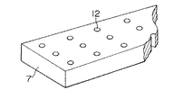
上記貫通孔は、図7に示すようにセメント系無機質材被覆成形体としたときに表裏にくるセメント系無機質板の補強繋ぎ及び発泡成形体との接着性向上による一体化や、寸法の安定性に効果がある。
貫通孔の大きさは、通常10〜30mmφ、間隔としては、通常100〜450mmであり、その断面は丸・四角・帯状の形状とすることもできる。
【0008】
(2)網状物
セメント系無機質材の収縮防止や耐衝撃性をより改良する為に上記発泡樹脂成形体を被覆するのに必要に応じて用いられる網状物としては、一般建築用に用いられる金属性の平ラス、メッシュ筋や樹脂性ネット、(耐アルカリ)ガラスネット等を使用することができる。
網状物を発泡樹脂成形体の表皮の表裏面及び小口面にステープル等で止め、ダイス背面部より挿入する。網状物の取付方法としては、ステープル止め以外に熱溶着や接着剤で止めることができる。
【0009】
(3)セメント系無機質材
セメント系無機質材としては、一般にセメントを主成分とする結合材を使用し、骨材、繊維、添加材等を配合し水と混練したものを押出機にかけることにより製造されるものである。
(a)セメント
セメントとしては、普通ポルトランドセメント、高炉セメント、早強セメント、アルミナセメント等を挙げることが出来る。
(b)骨材
骨材としては、砂、人工骨材、軽量骨材、着色骨材、天然着色骨材の粉砕品等を用いることが出来る。骨材の配合量は、セメント100重量部に対して一般に10〜50重量%、好ましくは20〜40重量%が良い。
【0010】
(c)繊維
繊維としては、樹脂系繊維、無機系繊維を使用することが出来る。
上記樹脂系繊維としては、ポリエステル、ナイロン、カーボン、ポリエチレン、ポリプロピレン等を使用することが出来る。
上記無機系繊維としては、ガラス繊維、石綿、等を使用することが出来る。
繊維の長さは、一般に6〜30mのものが用いられ、一般に1〜10重量%、好ましくは3〜8重量%を混練して使用することができる。
(d)添加剤
添加剤としては、粘度調整剤、空気連行剤等を添加する。
粘度調整剤としては、一般にメチルセルロース系の水溶性の糊剤を使用し、0.1〜5重量%添加する。空気連行剤は、表面活性剤で樹脂酸塩系、アルキルベンゼンスルフォン酸塩系、アルキルスルフォン酸トリエタノールアミン系などを使用することが出来る。
【0011】
[II]無機質材被覆発泡樹脂成形体の製造
(1)製造装置
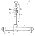
本発明の無機質材被覆発泡樹脂成形体を製造するための成形装置1としては、図1に示すような押出機2とダイス3と連結アダプター4とから基本的に構成されている。
【0012】
(a)押出機
上記押出機としては、一般的にセメント用の押出機を用いることができ、セメントの吐出量に応じて複数の押出機を並列して使用することができる。
押出機2は、図1に示すように、原料のセメント等を供給するためのホッパー2aと供給された原料を押し込むための押込み用スクリュー用モーター2bと押し込まれた原料を押し出すための主モーター2cとから基本的に構成されている。
(b)ダイス
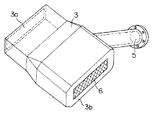
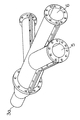
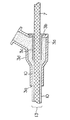
ダイスは、図2及び図3に示す様に押出機2から無機質結合材10を送り込む通路5と、ダイス3の背面部3b側に発泡樹脂成形体7の挿入口6及びダイス出口3aを有するものである。これらダイス3の断面は図4に示すようにダイス3内部に発泡樹脂成形体のガイド管3cを取付け、ダイス外管3dとの間の空間に無機質結合材の通路が形成されている。
(c)連結アダプター
連結アダプター4は、図1に示すように押出機2とダイス3を連結する。吐出量及び製品形状によって押出機2を2台連結することもできる。
【0013】
(2)製造方法
上記原材料のセメント系無機質結合材10を予め混合機にて混合し、更に混練機で混練したものを図1に示すような成形装置の押出機2のホッパー2aに投入して押出機2内で混練及び真空脱泡した後、ダイス3へ送り出し、ダイス3の背面部3b側から挿入した発泡樹脂成形体7及び必要に応じて用いられた網状物11の表面上にダイス3内で被覆し、押出機2の吐出圧力でダイスの出口3aへ送り出し、無機質材被覆発泡樹脂成形体13を成形する。
上記成形は一般に下記の成形条件下で行なわれる。
成形条件
成形温度:5〜40℃、好ましくは10〜30℃
成形速度:0.1〜2m/分、好ましくは0.5〜1m/分
成形圧力:0〜10kg/cm2
【0014】
[III ]無機質材被覆発泡樹脂成形体
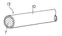
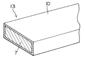
上記装置及び方法によって製造された本発明の無機質材被覆発泡樹脂成形体13は、芯材として発泡樹脂成形体7が用いられていることから軽量であり、外表面をセメント系無機質材10で形成されていることから、不燃で防火性を有しているし、強度も優れているので、建築物及びエクステリア関係に使用することができる。
【0015】
【実施例】
実施例1
被覆発泡樹脂成形体の製造
図3に示すダイスを図1に示す押出機(ヘンドレ社製径100mmφ)に連結し、無機質材として普通ポルトランドセメントを用い、骨材として硅砂7号、硅石粉を用い、繊維として16mm長さのポリエステル繊維を用い、添加剤としてメチルセルロースを用いて、これを水と混合し、混練機に2回通して混練した後、押出機ホッパーに投入し、ダイスの背面部側より60mmφの下記発泡樹脂成形体を挿入し、被覆して一体化させ、図5に示す径80mmφのセメント被覆発泡樹脂成形体を得た。
【0016】
<無機質結合材の配合>
普通ポルトランドセメント:40%
硅砂7号 :30%
硅石粉 :25%
ポリエステル繊維 :4 %
メチルセルロース :1 %
<発泡樹脂成形体>
発泡樹脂成形体は、発泡ポリスチレン樹脂(三菱化学BASF(株)製スチロポールJF−200)原料を30倍発泡したもの(60mmφ×1000mm)を使用した。
取り出し及び養生
ダイス出口に受け取りローラーを設置し、その上にポリエチレンフィルムを敷いて、押し出されるセメント被覆発泡樹脂成形体を受け取り、そのまま1週間常温養生した。
セメント被覆成形体の比重、強度と剥離強度を測定したところ、比重0.65、剥離強度4kg/cm2 であり、発泡樹脂成形体と良く接着し、軽くて強い丸棒を得ることが出来た。
なお、剥離強度の測定は1cm角に切断し、垂直引張によって実施した。
【0017】
実施例2
図2に示すようなダイスを用いて、下記の方法で行なった以外は実施例1と同様に行った。
<押出機>
セメント用押出機(ヘンドレ社製80mmφ)を図1に示すように取付けて行った。
<発泡樹脂成形体>
発泡樹脂成形体は、実施例1と同じ原料を使用し、3尺×6尺×400mmtのブロックに成形したものをニクロム線カッターにて290mm×40mm×1,800mmの大きさの平板状にカットした。
そして、そのボードの厚み方向に25mmφの貫通口を幅方向に2列、長さ方向に150mmピッチの間隔でハンダゴテを使って溶融穴を開けたものを使用した。
取り出した後、養生を行ったセメント被覆発泡樹脂成形体は、300mm×50mm×1,800mmの大きさで比重0.45、剥離強度4.0kg/cm2 であり、付着力良好で且つ軽く、強度のあるセメント被覆発泡樹脂成形体を得ることが出来た。
【0018】
【発明の効果】
本発明の無機質材被覆発泡樹脂成形体は、断熱性且つ軽量で防火性及び強度に優れていることから、建築物及びエクステリア関係等に使用することが出来る。
【図面の簡単な説明】
【図1】無機質材発泡樹脂成形体の成形装置の概略図である。
【図2】平板状成形体成形用のダイスの斜視図である。
【図3】丸棒状成形体成形用のダイスの斜視図である。
【図4】図2のダイスの水平断面図である。
【図5】丸棒状の無機質材被覆発泡樹脂成形体の斜視図である。
【図6】平板状の無機質材被覆発泡樹脂成形体の斜視図である。
【図7】貫通孔を設けた発泡成形体の斜視図である。
【符号の説明】
1 成形装置
2 押出機
2a ホッパー
2b 押込み用スクリュー
2c 主モーター
3 ダイス
3a ダイス出口
3b ダイス背面部
3c ガイド管
3d ダイス外管
4 連結アダプター
5 通路
6 発泡樹脂成形体挿入口
7 発泡樹脂成形体
10 無機質結合材
11 網状物
12 貫通孔
13 無機質材被覆発泡樹脂成形体[0001]
BACKGROUND OF THE INVENTION
The present invention relates to an inorganic material-covered foamed resin molded article that is lightweight, improves fire resistance and strength, and can be used for buildings and exteriors, using a foamed resin molded article.
[0002]
[Prior art]
As a method for producing a molded product made of an inorganic material-coated foamed resin that can be used in buildings and exteriors, a method of applying or applying a cement-based inorganic material to the surface of a foamed resin molded product is generally used. A method of post-bonding the veneer is adopted.
Further, inorganic extruded plates, inorganic hollow extruded plates and the like are used alone as outer wall materials and formwork materials for buildings.
In the method of applying or applying the cement-based inorganic material to the surface of the foamed resin molded body, in order to improve the coating workability, the cement-based inorganic material is softened by adding a lot of moisture, and then applied or applied. Therefore, there is a problem that the drying property is poor and it is difficult to form a pattern for improving the design of the surface. Furthermore, since it is a post-coating, there are many bubbles and moisture in the cement-based inorganic material, the strength after drying tends to be poor, and the strength tends to decrease due to freezing and thawing.
[0003]
Further, in the method of post-bonding the single sheet of inorganic material to the foamed resin molded body, an adhesive is used, so that the work process is complicated and expensive, and shrinkage occurs in the case of single-sided bonding. There is also a problem that warpage is likely to occur.
A single unit such as a cement-based inorganic extruded plate or a cement-based inorganic hollow extruded plate has sufficient performance in terms of fire resistance and strength, but the specific gravity is as heavy as 1.1 to 2.0. However, when the thickness of the veneer is increased, the plate becomes heavier and has poor workability and heat insulation.
In addition, since the cement-based inorganic hollow extrusion molded plate is a molded plate having a hollow portion, it can be thickened to express high strength. Since the method of providing is used, if too much press pressure is applied, the shape is deformed and it is difficult to provide a deep uneven pattern. Further, in order to increase the thickness, it is necessary to increase the thickness and the thickness of the rib portion, and thus there is a problem that the weight becomes too heavy. Furthermore, there is a problem that workability and heat insulation performance are also poor.
[0004]
[Problems to be solved by the invention]
An object of the present invention is to provide an inorganic material-covered foamed resin molded body that improves the fire resistance and strength of a cement-based inorganic material by taking advantage of the heat insulating properties and light weight of the foamed resin molded body.
[0005]
[Means for Solving the Problems]
The present inventor has studied various methods for coating a foamed resin molded body with a cement-based inorganic material, and as a result of earnest research, has completed the invention relating to the method for producing the inorganic material-coated foamed molded body of the present invention. It is a thing.
That is, the manufacturing method of the inorganic material-coated foamed resin molded body of the present invention comprises coating the foamed resin molded body inserted from the back side of the die of the extruder with a cement-based inorganic material extruded from the extruder in the die. A method of manufacturing an inorganic material-coated foamed resin molded body to be integrated, wherein the die has a guide pipe of the foamed resin molded body attached to the inside of the die, and an inorganic bond passage is formed in a space between the die outer pipe. It is a thin die with a thin inorganic material and has excellent lightness, heat insulation, fire resistance and strength.
[0006]
DETAILED DESCRIPTION OF THE INVENTION
[1] Raw Material (1) Foamed Resin Molded Body As the foamed resin molded body used in the present invention, a foamed body of a thermoplastic resin and a thermosetting resin can be used. Examples of the thermoplastic resin foam include foams such as polystyrene, impact-resistant polystyrene, polypropylene, polyethylene, and polyethylene terephthalate (PET) resin.
Moreover, as said thermosetting resin foam, foams, such as a urethane resin, a phenol resin, a melamine resin, and a urea resin, can be mentioned.
Among these, it is preferable to use a thermoplastic resin foam. In particular, it is most preferable to use a polystyrene-based foam from the viewpoint of moldability and cost.
As the expansion ratio of the above-mentioned foamed resin molded product, polystyrene generally has a magnification of 3 to 80 times, preferably 5 to 60 times.
When the foamed resin molded article having an expansion ratio of less than the above range is used, it is not preferable because the resin weight is heavy and the cost is increased. When the above range is exceeded, it is difficult to obtain an inorganic material-covered molded article having a dimensional accuracy as designed because the foam is easily deformed due to the internal pressure applied at the time of being integrally coated with the cement-based inorganic material in the die.
[0007]
As the shape of the foamed resin molded product, a molded product, a block cut product, and the like can be used, and those having through holes in the groove and the thickness direction are preferable.
The groove forms a rib of a cement-based inorganic binder, and may be inserted vertically, horizontally, or obliquely. The depth of the groove is usually 2 to 5 mm, the width is 3 mm or more, and it is effective for integration and dimensional stability due to adhesion between the foamed molded article and the cement-based inorganic binder.
As shown in FIG. 7, the through-hole is integrated by reinforcing the cement-based inorganic plate on the front and back of the cement-based inorganic material-coated molded body and improving the adhesiveness with the foamed molded body, and dimensional stability. Is effective.
The size of the through-hole is usually 10 to 30 mmφ, and the interval is usually 100 to 450 mm, and the cross section can be round, square, or belt-shaped.
[0008]
(2) Reticulates As a reticulate used as necessary to cover the foamed resin molded body in order to further improve the shrinkage prevention and impact resistance of the cementitious inorganic material, a metal used for general construction is used. Flat laths, mesh streaks, resin nets, (alkali-resistant) glass nets, and the like can be used.
The net-like material is fixed to the front and back surfaces and the small edge surface of the skin of the foamed resin molding with staples or the like, and inserted from the back surface of the die. As a method for attaching the net-like material, it can be stopped by heat welding or adhesive other than stapling.
[0009]
(3) Cement-based inorganic material As a cement-based inorganic material, generally a cement-based binder is used, and a mixture of aggregates, fibers, additives, etc. and kneaded with water is applied to an extruder. It is manufactured.
Examples of (a) cement cement include ordinary Portland cement, blast furnace cement, early-strength cement, and alumina cement.
(B) As aggregates, sand, artificial aggregates, lightweight aggregates, colored aggregates, pulverized products of natural colored aggregates, and the like can be used. The amount of aggregate is generally 10 to 50% by weight, preferably 20 to 40% by weight, based on 100 parts by weight of cement.
[0010]
(C) As a fiber fiber, a resin fiber and an inorganic fiber can be used.
As the resin fiber, polyester, nylon, carbon, polyethylene, polypropylene, or the like can be used.
As the inorganic fiber, glass fiber, asbestos, or the like can be used.
The fiber length is generally 6 to 30 m, and generally 1 to 10% by weight, preferably 3 to 8% by weight, can be used after kneading.
(D) As an additive additive, a viscosity modifier, an air entraining agent or the like is added.
As the viscosity modifier, a methylcellulose-based water-soluble paste is generally used, and 0.1 to 5% by weight is added. As the air entraining agent, a resin acid salt type, an alkylbenzene sulfonate type, an alkyl sulfonic acid triethanolamine type or the like can be used as a surfactant.
[0011]
[II] Manufacture of Inorganic Material-Coated Foamed Resin Molded Body (1) Manufacturing Apparatus As a molding apparatus 1 for manufacturing the inorganic material-coated foamed resin molded body of the present invention, an
[0012]
(A) Extruder As the above-mentioned extruder, generally, an extruder for cement can be used, and a plurality of extruders can be used in parallel according to the discharge amount of cement.
As shown in FIG. 1, the
(B) As shown in FIGS. 2 and 3, the dice die has a
(C) Connection adapter The connection adapter 4 connects the
[0013]
(2) Manufacturing method The raw material cement-based
The above molding is generally performed under the following molding conditions.
Molding conditions Molding temperature: 5-40C, preferably 10-30C
Molding speed: 0.1-2 m / min, preferably 0.5-1 m / min Molding pressure: 0-10 kg / cm 2
[0014]
[III] Inorganic material-coated foamed resin molded body The inorganic material-coated foamed resin molded
[0015]
【Example】
Example 1
Production of coated foamed resin molded body The die shown in Fig. 3 was connected to the extruder shown in Fig. 1 (diameter 100 mmφ manufactured by Hendre), ordinary portland cement was used as the inorganic material, and
[0016]
<Inorganic binder composition>
Normal Portland cement: 40%
Minato 7: 30%
Meteorite powder: 25%
Polyester fiber: 4%
Methyl cellulose: 1%
<Foamed resin molding>
As the foamed resin molding, a foamed polystyrene resin (Mitsubishi Chemical BASF Co., Ltd. Styropol JF-200) raw material 30 times foamed (60 mmφ × 1000 mm) was used.
Taking out and curing A receiving roller was installed at the die outlet, a polyethylene film was laid on the receiving roller, and the cement-coated foamed resin molded body to be extruded was received and cured at room temperature for one week.
The specific gravity, strength, and peel strength of the cement-coated molded body were measured. As a result, the specific gravity was 0.65 and the peel strength was 4 kg / cm 2 , and it adhered well to the foamed resin molded body, and a light and strong round bar could be obtained. .
The peel strength was measured by cutting into 1 cm square and by vertical tension.
[0017]
Example 2
Using a die as shown in FIG. 2, the same procedure as in Example 1 was performed except that the method was as follows.
<Extruder>
A cement extruder (Hendre 80 mmφ) was attached as shown in FIG.
<Foamed resin molding>
The foamed resin molding is the same raw material as in Example 1, and is molded into a 3 x 6 x 400 mmt block and cut into a flat plate of 290 mm x 40 mm x 1,800 mm with a nichrome wire cutter. did.
Then, through-holes of 25 mmφ in the thickness direction of the board were used in which two holes in the width direction and solder holes were used to form fusion holes at intervals of 150 mm in the length direction.
After being taken out, the cement-coated foamed resin molded article that had been cured was 300 mm × 50 mm × 1,800 mm in specific gravity of 0.45, peel strength of 4.0 kg / cm 2 , good adhesion and light, A strong cement-coated foamed resin molded product could be obtained.
[0018]
【The invention's effect】
Since the inorganic material-coated foamed resin molded article of the present invention is heat-insulating, lightweight, and excellent in fire resistance and strength, it can be used for buildings and exteriors.
[Brief description of the drawings]
FIG. 1 is a schematic view of a molding apparatus for an inorganic material foamed resin molding.
FIG. 2 is a perspective view of a die for forming a flat molded body.
FIG. 3 is a perspective view of a die for forming a round bar-shaped molded body.
4 is a horizontal cross-sectional view of the die of FIG.
FIG. 5 is a perspective view of a round bar-shaped inorganic material-coated foamed resin molded body.
FIG. 6 is a perspective view of a flat inorganic material-coated foamed resin molding.
FIG. 7 is a perspective view of a foamed molded body provided with through holes.
[Explanation of symbols]
DESCRIPTION OF SYMBOLS 1
Claims (3)
Priority Applications (1)
| Application Number | Priority Date | Filing Date | Title |
|---|---|---|---|
| JP2761097A JP3607031B2 (en) | 1997-02-12 | 1997-02-12 | Method for producing inorganic material-coated foamed resin molding |
Applications Claiming Priority (1)
| Application Number | Priority Date | Filing Date | Title |
|---|---|---|---|
| JP2761097A JP3607031B2 (en) | 1997-02-12 | 1997-02-12 | Method for producing inorganic material-coated foamed resin molding |
Publications (2)
| Publication Number | Publication Date |
|---|---|
| JPH10217386A JPH10217386A (en) | 1998-08-18 |
| JP3607031B2 true JP3607031B2 (en) | 2005-01-05 |
Family
ID=12225709
Family Applications (1)
| Application Number | Title | Priority Date | Filing Date |
|---|---|---|---|
| JP2761097A Expired - Fee Related JP3607031B2 (en) | 1997-02-12 | 1997-02-12 | Method for producing inorganic material-coated foamed resin molding |
Country Status (1)
| Country | Link |
|---|---|
| JP (1) | JP3607031B2 (en) |
Families Citing this family (4)
| Publication number | Priority date | Publication date | Assignee | Title |
|---|---|---|---|---|
| JP4633585B2 (en) * | 2004-09-13 | 2011-02-16 | ヤマハリビングテック株式会社 | Method for producing resin-containing laminate |
| JP4859747B2 (en) * | 2007-05-07 | 2012-01-25 | ミサワホーム株式会社 | Freeze-thaw test method |
| JP2014040069A (en) * | 2012-08-23 | 2014-03-06 | Kmew Co Ltd | Method for producing extruded cement plate |
| EP2914795B1 (en) * | 2012-11-05 | 2017-02-22 | Basf Se | Process for the preparation of profiled elements |
-
1997
- 1997-02-12 JP JP2761097A patent/JP3607031B2/en not_active Expired - Fee Related
Also Published As
| Publication number | Publication date |
|---|---|
| JPH10217386A (en) | 1998-08-18 |
Similar Documents
| Publication | Publication Date | Title |
|---|---|---|
| US20040131714A1 (en) | Apparatus for preparing a gypsum wallboard core | |
| EP2970006B1 (en) | Mat faced gypsum board comprising hydrophobic finish | |
| JP2006524626A (en) | SOUND ABSORBING PANEL CONTAINING INTERLOCKING MATRIX OF SOLIDED Gypsum and Method for Producing the | |
| JP3607031B2 (en) | Method for producing inorganic material-coated foamed resin molding | |
| CN106564218A (en) | Plastic composite board and forming equipment | |
| CN100420557C (en) | Production technology and equipment of air-entrained decorative panels | |
| CN107433720B (en) | A preparation method of refractory lightweight particles and wood-plastic composite board | |
| CN106630837A (en) | Composite-polydopamine-membrane-modified regenerated EPS particle and portland cement composite foamed warming plate and preparation method thereof | |
| CN106810151A (en) | A kind of emulsified wax coating modification regeneration EPS nanoparticulate silicates cementitious composite foaming insulation boards and preparation method thereof | |
| CN102535792B (en) | Method for manufacturing ceiling | |
| CN106584928A (en) | Plastic composite sheet material and forming die | |
| JP2009156015A (en) | Thermal insulation panel | |
| CN106810152A (en) | A kind of regeneration EPS particle doped silicate cementitious composite foaming insulation boards of polymolecularity and preparation method thereof | |
| CN107433721A (en) | A kind of preparation method of inorfil and wood-plastic composite panel | |
| US20040173928A1 (en) | Method of forming building materials mostly consisting of magnesium oxide | |
| CN107501687A (en) | A kind of ecological environment-friendly type foamed wall slab and preparation method thereof | |
| JPS63176144A (en) | Light-weight gypsum cured body and manufacture thereof | |
| GB2344341A (en) | Forming mixture and constructional material | |
| JPH08300550A (en) | Lightweight gypsum hardened body | |
| CN106800394A (en) | A kind of silica sol modified regeneration EPS nanoparticulate silicates cementitious composite foaming insulation boards of hydridization and preparation method thereof | |
| CN112227547A (en) | A kind of flame retardant thermal insulation board and its making method and thermal insulation wall | |
| JPH11342554A (en) | Composite laminate and acoustic panel | |
| JPS63182271A (en) | Lightweight gypsum hardened body and manufacture | |
| JPH08281862A (en) | Lightweight gypsum hardened body and method for producing the same | |
| JPS6218511B2 (en) |
Legal Events
| Date | Code | Title | Description |
|---|---|---|---|
| A977 | Report on retrieval |
Free format text: JAPANESE INTERMEDIATE CODE: A971007 Effective date: 20040401 |
|
| A131 | Notification of reasons for refusal |
Free format text: JAPANESE INTERMEDIATE CODE: A131 Effective date: 20040629 |
|
| A521 | Written amendment |
Free format text: JAPANESE INTERMEDIATE CODE: A523 Effective date: 20040820 |
|
| TRDD | Decision of grant or rejection written | ||
| A01 | Written decision to grant a patent or to grant a registration (utility model) |
Free format text: JAPANESE INTERMEDIATE CODE: A01 Effective date: 20040910 |
|
| A61 | First payment of annual fees (during grant procedure) |
Free format text: JAPANESE INTERMEDIATE CODE: A61 Effective date: 20041006 |
|
| R150 | Certificate of patent (=grant) or registration of utility model |
Free format text: JAPANESE INTERMEDIATE CODE: R150 |
|
| FPAY | Renewal fee payment (prs date is renewal date of database) |
Free format text: PAYMENT UNTIL: 20071015 Year of fee payment: 3 |
|
| FPAY | Renewal fee payment (prs date is renewal date of database) |
Free format text: PAYMENT UNTIL: 20081015 Year of fee payment: 4 |
|
| FPAY | Renewal fee payment (prs date is renewal date of database) |
Free format text: PAYMENT UNTIL: 20091015 Year of fee payment: 5 |
|
| FPAY | Renewal fee payment (prs date is renewal date of database) |
Free format text: PAYMENT UNTIL: 20101015 Year of fee payment: 6 |
|
| FPAY | Renewal fee payment (prs date is renewal date of database) |
Free format text: PAYMENT UNTIL: 20111015 Year of fee payment: 7 |
|
| FPAY | Renewal fee payment (prs date is renewal date of database) |
Free format text: PAYMENT UNTIL: 20121015 Year of fee payment: 8 |
|
| FPAY | Renewal fee payment (prs date is renewal date of database) |
Free format text: PAYMENT UNTIL: 20121015 Year of fee payment: 8 |
|
| FPAY | Renewal fee payment (prs date is renewal date of database) |
Free format text: PAYMENT UNTIL: 20131015 Year of fee payment: 9 |
|
| R250 | Receipt of annual fees |
Free format text: JAPANESE INTERMEDIATE CODE: R250 |
|
| LAPS | Cancellation because of no payment of annual fees |