JP3602930B2 - Paper post-processing equipment - Google Patents
Paper post-processing equipment Download PDFInfo
- Publication number
- JP3602930B2 JP3602930B2 JP05626197A JP5626197A JP3602930B2 JP 3602930 B2 JP3602930 B2 JP 3602930B2 JP 05626197 A JP05626197 A JP 05626197A JP 5626197 A JP5626197 A JP 5626197A JP 3602930 B2 JP3602930 B2 JP 3602930B2
- Authority
- JP
- Japan
- Prior art keywords
- paper
- sheet
- staple tray
- tray
- transport path
- Prior art date
- Legal status (The legal status is an assumption and is not a legal conclusion. Google has not performed a legal analysis and makes no representation as to the accuracy of the status listed.)
- Expired - Fee Related
Links
Images


Description
【0001】
【発明の属する技術分野】
本発明は、複写機、ファクシミリ、プリンタ等の画像形成装置の排紙部に接続される用紙後処理装置に関する。より具体的には、画像形成装置の排紙部から排紙される画像形成済みの用紙を受け入れて、排紙トレイにそのまま排紙するか、あるいは一旦スティプルトレイに収容し、所定枚数ごとにスティプル綴じを行う用紙後処理装置に関する。
【0002】
【従来の技術】
上述したように、用紙後処理装置においては、画像形成装置から受け入れた用紙を所定枚数ごとにスティプル綴じしてから排紙トレイに排紙するモード(スティプルモード)と、スティプル綴じを行わないでそのまま排紙トレイに排紙するモード(ノンスティプルモード)とがある。
【0003】
従って、用紙受け入れ部から排紙部に至るまでの用紙搬送路としては、スティプルモード用とノンスティプルモード用の搬送路が必要となる(両者が全く独立しているか、あるいは一部が共通であるかは別にして)。
【0004】
例えば、特開平4−243767号公報には、スティプルされた用紙を排出する搬送路と、ストレート排紙の搬送路が別々に分かれた構成が示されている。
【0005】
また、特開平7−172658号公報には、スティプルトレイ内へ用紙をスタックする際に、戻しローラによってスティプルトレイ方向へ押し付ける機構が示されている。
【0006】
しかしこれらの従来装置の場合、搬送路を別々に分けたり、スティプルトレイ内へ用紙をスタックさせるための機構を備えるため、構成が複雑でコストアップとなる。
【0007】
そこで、用紙を排紙トレイへ直接導く第1の搬送路と、スティプルトレイに導く第2の搬送路と、第2の搬送路に進入した用紙をスイッチバックさせて第1の搬送路に合流させる第3の搬送路とを備える共に、第2の搬送路上には、スティプルトレイ内に用紙をスタックさせる際に用紙の後端をスティプルトレイ方向へ押し付けるブラシローラを備え、スティプルトレイ内へ用紙をスタックさせる際に、ブラシローラを例えば時計方向に回転させることにより、用紙の後端をスティプルトレイ側へ押し付けるようにする構成が提案されている。
【0008】
【発明が解決しようとする課題】
しかし、上記の構成の用紙後処理装置においては、割り込み処理で、用紙をストレートに排出する際は、ブラシローラが、例えば反時計方向に回転することになるため、一度スティプルトレイ内に押し付けてスタックされた用紙が、スティプルトレイに向かう搬送路側へ押し戻されてしまい、割り込み処理が終了し、再度用紙をスティプルトレイ内へ搬送する際に、押し戻された用紙が搬送の妨げになり、紙詰まりを起こすという不具合があった。
【0009】
本発明の第1の課題は、スティプルトレイ内に用紙がある状態でも、紙詰まりを起こすことなく、割り込みでストレート排紙を行うことができる用紙後処理装置を提供することである。
本発明の第2の課題は、ブラシローラに引っ掛かることなく確実に用紙を下降させることができる用紙後処理装置を提供することである。
本発明の第3の課題は、ブラシローラに引っ掛かることなく確実に用紙を上昇させて元の位置に戻すことができる用紙後処理装置を提供することである。
【0010】
【課題を解決するための手段】
上記第1の課題は、画像形成装置の排紙部から排紙される用紙を受け入れて、所定枚数ごとにスティプル綴じを行うか、又はスティプル綴じを行わないで排紙トレイ上に用紙を積載する用紙後処理装置において、第1の搬送ローラを有し、用紙を前記排紙トレイへ直接導く第1の搬送路と、スティプルトレイに導く第2の搬送路と、前記第2の搬送路に進入した用紙をスイッチバックさせて前記第1の搬送路に合流させる第3の搬送路と、前記第2の搬送路上には、該第2の搬送路に進入した用紙をそのまま前記スティプルトレイヘ搬送するか、あるいは該第2の搬送路に進入した用紙を反転して前記第3の搬送路から前記第1の搬送路へ搬送する正逆転可能な第2の搬送ローラと、前記第2の搬送路上には、前記第1、第2の搬送ローラと連動して回転するとともに、前記スティプルトレイ内に用紙をスタックさせる際に用紙の後端を前記スティプルトレイ方向へ押し付けるブラシローラと、前記スティプルトレイ内に用紙がスタックされた状態で割り込み処理として、前記第1の搬送路により用紙を直接前記排紙トレイ上へ排出させる場合には、前記スティプルトレイ内の用紙の後端が前記ブラシローラに接触しない位置まで用紙を下降させ、割り込み処理が終了し、再度、前記スティプルトレイ内へ用紙を前記第2の搬送路から搬送させる場合は、前記下降させた用紙を元の位置まで上昇させる制御手段を備えた第1の手段により解決される。
【0011】
上記第1の課題は、第1の手段において、前記スティプルトレイは、用紙を支持して上昇、下降する排紙爪を備えており、この排紙爪の駆動によって用紙を上昇、下降させる第2の手段により解決される。
上記第2の課題は、第1の手段において、前記スティプルトレイは傾斜配置とされるとともに、前記スティプルトレイ内の用紙の下端を支え、上昇あるいは下降することにより該用紙を前記スティプルトレイ内で上昇あるいは下降させる排紙爪を備え、前記スティプルトレイ内の用紙を前記排紙爪により下降させる際に、前記ブラシローラを反時計方向に回転させることにより前記下降する用紙の上端を下方へ押す第3の手段により解決される。
上記第3の課題は、第1の手段において、前記スティプルトレイは傾斜配置とされるとともに、前記スティプルトレイ内の用紙の下端を支え、上昇あるいは下降することにより該用紙を前記スティプルトレイ内で上昇あるいは下降させる排紙爪を備え、前記スティプルトレイ内の用紙を前記排紙爪により上昇させる際に、前記ブラシローラを時計方向に回転させることにより前記上昇してくる用紙の上端を上方へ押し上げる第4の手段により解決される。
【0012】
【発明の実施の形態】
以下、本発明の実施の形態を図面に基づいて説明する。
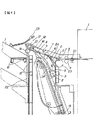
図1は一実施の形態に係る用紙後処理装置の全体構成図である。
【0013】
図1に示す用紙後処理装置は、画像形成装置1の排紙部に取り付けられており、画像形成装置1より排紙された用紙を切換爪2により直接排紙トレイ(シフトトレイ)3へ導くソート・スタック用の第1搬送路A及び、スティプル綴じまたは反転するための第2搬送路B、正逆転可能な搬送ローラ8の逆転により第2搬送路Bに進入した用紙を再び第1搬送路Aに導く第3搬送路Cを備えている。なお、2aは切換爪2の回動中心である。
【0014】
第3搬送路Cの最下流側に配置した前記排紙トレイ3は、スティプルを行わない用紙とスティプル綴じされた用紙の両者をスタックする機能を有する。
【0015】
本用紙後処理装置の入口部近傍には画像形成装置1より排紙された用紙を受け取る搬送ローラ4及び従動ローラ5を備え、さらにその直前部分には入口センサS1が備えられており、搬送される用紙の先端及び後端が検知されるようになっている。
【0016】
前記搬送ローラ4の下流には、前記切換爪2が配されており、この切換爪2を図示しないソレノイド及びスプリング等により、一点鎖線の位置と実線位置とに切り換えることによって画像形成装置1より排紙された用紙の搬送方向を、第1搬送路A及び第2搬送路Bの何れかの方向へ導くことができるようになっている。
【0017】
第1搬送路Aには搬送ローラ6及びそれに従動する従動ローラ7が配されており、この第1搬送路Aは画像形成装置1より排紙され、一点鎖線位置に切り換えられた切換爪2により導かれた用紙を直接排紙トレイ3に導く。
【0018】
また、第2搬送路Bにおいても、後述するブラシを備えた前記搬送ローラ8及び従動ローラ9が配されており、この第2搬送路Bは画像形成装置1より排紙され、実線位置に切り換えられた切換爪2により導かれた用紙をスティプル時にはスティプルユニットDへ、また反転時には第3搬送路Cへ導くようになっている。
【0019】
なお、図1に示す他のユニットについては後述する図2以下で説明する。
図2はスティプルユニットDの側面(図1を正面とした場合の側面)図、図3は同、正面図である。
スティプルユニットDは、用紙の幅方向に移動可能であって、用紙の所定位置にスティプル綴じを行うスティプラ10、搬送方向に直交する方向へ移動可能であって用紙の幅方向を揃えるためのジョガーフェンス11、スティプル綴じされた用紙を排紙トレイ3へ排紙するための排紙ベルト12、及びそれに固定された排紙爪13、スティプルトレイ20、基準フェンス21等で構成されている。
【0020】
S2は排紙爪13の位置を検知するセンサであり、スティプルユニットDに導かれた用紙のサイズに応じてその用紙の後端の位置が常に一定になるように、排紙爪3は、S2でその位置が検知されることによって、その用紙サイズに合った位置に調節される。
【0021】
なお、図2に示すように、基準フェンス21は用紙反転時の用紙最大幅の位置より外側に配置され、スティプル時の用紙の基準位置になっている。
【0022】
ここで、排紙爪13は、スティプルトレイ(用紙整合トレイ部)20上に導かれた用紙の先端部が突き当てられて揃えられるフェンスとしての機能と、スティプル済みの用紙束を排紙トレイ3に向けて送り出す機能を兼ねている。
【0023】
図4は用紙排紙部の拡大構成図である。
排紙トレイ3への排紙口には、排紙ローラ14及びそれに従動する排紙従動ローラ17が配置されており、スティプルを行わない用紙やスティプル綴じされた用紙、及び反転された用紙を排紙トレイ3に排紙する。
【0024】
排紙従動ローラ17は、通常は排紙ローラ14に接触した位置にいるが、排紙される用紙の厚さ及びこしに応じて支点aを中心として、排紙ガイド板18と共に矢印の方向に自動的に移動が可能となっている。例えば、一点鎖線の位置に移動する。
排紙トレイ3は、上下ガイドコロ15によりガイド板22に沿って上下方向への移動が可能となっており、図示しない駆動機構により駆動される。排紙トレイ3はまた、シフトガイドコロ16により用紙排紙方向に対して直交した方向(図の鉛直方向)にも移動可能となっており、これも図示しない駆動機構によりシフト動作が行われ、排紙された用紙を仕分けられるようになっている。
【0025】
S3は、排紙された用紙の上面を検知するための上面検知センサであり、排紙されスタックされた用紙の上面が常に排紙ローラ14に対して所定の位置になるように、排紙トレイ3の高さが調整される。
なお、図1において、23は反転ガイド、S4は反転入口センサを示す。
【0026】
本実施の形態の排紙動作としては、スティプルを行わず、1枚ごとに直接(ストレートに)排紙トレイ3に用紙を排紙するソート・スタットモードと、スティプル綴じをした後に排紙するスティプルモードと、反転した後に排紙する反転モードとの3つに分けられていて、画像形成装置1の図示しない操作部の選択キーにより各モードが選択できるようになっている。
【0027】
以下、各モードごとに分けて説明する。
(1)ソート・スタックモード
切換爪2は、図1の一点鎖線の位置となり、画像形成装置1より排紙された用紙は、第1搬送路Aへ送られ、搬送ローラ6により排紙口へ送られる。このとき、常に排紙従動ローラ17は、排紙ローラ14に対して自重で加圧された状態で接しており、用紙はこれにより排紙トレイ3に排紙される。
【0028】
排紙された用紙は、次々に排紙トレイ3にスタックされる。センサS3がスタックされた用紙の上面を検知することにより、その用紙の上面が常に一定の高さになるように排紙トレイ3の高さが調整される。また、必要に応じて排紙トレイ3は、用紙排紙方向に対して直交する方向に移動してシフト動作を行い、用紙の仕分けを行う。
【0029】
また、後述する反転モードのときも、排紙トレイ3は同様の昇降及び仕分け動作を行う。
【0030】
(2)スティプルモード
切換爪2は図1の実線の位置となり、画像形成装置1より排紙された用紙は、反転して第2搬送路Bへ導かれ、スティプルユニットDへ搬送される。このとき、排紙爪13は、センサS2の検出出力により、用紙の後端が常に搬送ローラ8に対して用紙搬送方向の下流側に一定の間隔を置いてスタックされるように、スティプルトレイ20の搬送経路上を上下方向に移動される。
また、搬送ローラ8の同軸上には、このローラ8の直径より大きなブラシローラ8′が設けられている。このブラシローラ8′により、スティプルトレイ20に導かれた用紙は、排紙爪13にその先端が突き当たると同時に、その後端がスティプルトレイ20方向に押し付けられた状態でスタックされる。
【0031】
次に、用紙は、ジョガーフェンス11を搬送方向に直交する方向に往復移動することにより基準フェンス21に向かって寄せ動作が行われる。従って、その用紙は基準フェンス21及び排紙爪13に突き当たった状態でスタックされる。
ジョガーフェンス11は、用紙がスティプルトレイ20に進入するごとに同様の寄せ動作を繰り返し、用紙は揃えられた状態でスタックされる。
【0032】
次に、スティプラ10により用紙の綴じ動作が行われる。綴じ動作後、スティプル済みの用紙束は、前記搬送方向の基準となっていた排紙爪13上方向に移動させることにより排紙ローラ14方向へ搬送され、排紙ローラ14により排紙トレイ3上に排紙される。排紙後、その用紙束は、自重でガイド板22に突き当たり、後端が揃えられてスタックされる。スタックされた用紙束は、ソート・スタックモードのときと同様に、その用紙束の上面が常に一定の位置になるように排紙トレイ3の高さが調整される。
【0033】
(3)反転モード
切換爪2は、前記スティプルモードと同様に、図1の実線の位置となり、画像形成装置1より排紙された用紙は、反転して第2搬送路Bへ導かれる。このとき、切換爪2の先端は反転ガイド23にオーバーラップした状態で加圧されており、用紙はこれを押し退けるように搬送される。
次に、その用紙の後端が切換爪2を通過して反転入口センサS4により検知されると搬送ローラ8が逆転する。用紙は、反転した状態でスイッチバックして切換爪2により第3搬送路Cへ導かれ、第3搬送路C及び第1搬送路Aを経て、搬送ローラ6により排紙口へ送られる。
【0034】
なお、この反転モードの際には、排紙ベルト12に固定された排紙爪13は、第2搬送路Bへ導かれた用紙の先端が当たらない位置に逃げている。この位置は、排紙爪13の位置を検知するセンサS2により設定される。
【0035】
次に、本発明の実施の形態の動作について説明する。
スティプルモードが選択されたとき、画像形成装置1から排出された用紙は、切換爪2によって第2搬送路Bを経てスティプルユニットDへ導かれる。
その際に、排紙爪13は、用紙サイズに応じてスティプルトレイ20の搬送経路に沿って移動され、排紙爪13に用紙先端が突き当たったときに、用紙後端が搬送ローラ8と従動ローラ9のニップ部から離れていて、かつ、ブラシローラ8′と接触する状態になるような位置に停止される。よって、用紙は、その後端がブラシローラ8′により掻き落とされ、スティプルトレイ20方向に押し付けられた状態でスタックされる。
また、スティプル時には、排紙爪13は、スティプラ10の綴じ位置に合わせてスティプルトレイ20の搬送経路上に沿って下方向に移動される。綴じ位置に移動された用紙は、スティプラ10により所定の位置にスティプル綴じが行われる(1個所または複数個所)。そしてスティプル後、用紙は排紙爪13をスティプルトレイ20の搬送経路上に沿って上方向に移動させることにより排紙ローラ14方向へ搬送され、排紙ローラ14により排紙トレイ3に排紙される。
【0036】
図5は本発明のスティプル処理動作の一例を示すフローチャートである。
スティプルモードにおいて、画像形成装置1から排紙されて来る用紙のサイズに応じて、用紙後端がブラシローラ8′に対して一定の位置になるように排紙爪13を移動する(S1,S2)。
スティプル綴じされるべき一部(1セット)の最終用紙のスタックが終了されたかどうか判断し(S3)、終了された場合(S3でY)はS4へ行き、終了されていない場合(S3でN)はS3を繰り返す。
スタックが終了された後(S3でY)、スティプルモード選択に選択されたスティプル綴じが1カ所綴じか、複数カ所綴じかを判断し(S4)、複数個所綴じの場合(S4でY)S8へ行き、1個所綴じの場合(S4でN)S5へ行く。
【0037】
1カ所綴じの場合(S4でN)は以下のようになる。
用紙サイズに応じて、排紙爪13を用紙受け入れ位置からスティプラ10の綴じ位置にスティプルトレイ20の搬送経路上に沿って下方向に所定の量だけ移動させる(S5)。そしてスティプラ10にて用紙の所定位置に綴じ処理を行う(S6)。次にスティプル動作が終了した用紙束を、排紙爪13をスティプルトレイ20の搬送経路上に沿って上方向に移動させることにより排紙ローラ14方向へ搬送し、排紙ローラ14により排紙トレイ3に排紙する(S7)。
【0038】
複数カ所綴じの場合(S4でY)は以下のようになる。
用紙サイズに応じて排紙爪13を用紙受け入れ位置からスティプラ10の綴じ位置に移動させる(S8)。そして、スティプラ10にて用紙の所定位置に1番目の綴じ処理を行う(S9)。次に、スティプラ10を2番目の綴じ処理を行う位置に移動させ(S10)、スティプラ10にてその位置に2番目の綴じ処理を行う。そして、この動作をスティプル綴じ数に応じて所定回数繰り返す(S12)。
次にスティプル動作が終了した用紙束を、排紙爪13をスティプルトレイ20の搬送経路上に沿って上方向に移動させることにより排紙ローラ14方向へ搬送し、排紙ローラ14により排紙トレイ3に排紙する(S7)。
【0039】
このような本発明の実施の形態によれば、排紙爪13、用紙端部を揃える後端フェンスとしての機能も備えているので、スタック動作、スティプル時の用紙移動動作、スティプル動作終了後の用紙排紙動作を行わせることができ、構成が簡略化でき、省スペース化が可能になると共にコストダウンができる。
また、本発明の実施の形態によれば、排紙爪(後端フェンス)13はスティプルトレイ20の搬送経路上に沿って上下に移動可能であるので、ソフトウェア(装置内蔵のコンピュータプログラム)によりスティプル綴じ位置等の微妙な調整が可能となる。
【0040】
図6は用紙後処理装置の各種駆動負荷とメイン制御基板の結線状態を示す回路図である。
メイン制御基板100には、入口部の搬送ローラ4を駆動する入口モータ101、その他の搬送ローラ6,8及び排紙ローラ14を駆動する搬送モータ102、排紙トレイ3をシフトするシフトモータ103、ジョガーフェンス11を駆動するジョガーモータ105、排紙ベルト12を駆動する、即ち排紙爪13を駆動する排紙ベルトモータ106、スティプルモータ107、及び切換爪2を駆動するソレノイド108が接続されて制御される。
【0041】
次に、本発明の実施の形態に係るスティプルトレイ内の用紙の昇降制御について説明する。
図7は本発明の実施の形態に係るスティプルトレイ内の用紙の昇降制御を示すフローチャートである。
まず、スティプルモードか否か判断する(S21)。スティプルモードの場合は(S21でY)、搬送モータ102によって搬送ローラ6,8及びブラシローラ8′(及び排紙ローラ14)を時計方向に回転させて用紙をスティプルトレイ20に向けて搬送する(S22)。次に、スティプルトレイ20上の排紙爪13が通常より下降した位置にあるか否か判断する(S23)。なお、スティプルトレイ20内の用紙の先端(図1ないし図4上では下端)は、排紙爪13によって支持されているので、排紙爪13の位置が即ち用紙の位置ということになる。
排紙爪13が下降した位置にあれば(S23でY)、排紙ベルトモータ106を駆動することで、排紙爪13を所定位置まで上昇させる(S24)。この状態でスティプルトレイ20へ用紙をスタックさせる(S25)。そして、スティプル指令に基づきスティプル動作が実行される(S26でY、S27)。スティプル後は、用紙束を排紙トレイ3へ排出する(S28)。
【0042】
スティプルモードでない場合は(S21でN)、次にストレート排紙モードか否か判断する(S29)。ストレート排紙の場合(S29でY)、搬送モータ102によって搬送ローラ6,8及び排紙ローラ14及びブラシローラ8′を反時計方向に回転させ、用紙を搬送する(S30)。
次にスティプルトレイ20内に用紙があるか否か判断する(S31)。スティプルトレイ20内に用紙がある場合は(S31でY)、排紙爪13を下降させる。
【0043】
即ち用紙の後端がブラシローラ8′に接触しない位置まで用紙を下降させる(S32)。そしてストレート排紙の用紙を排紙トレイ3に排出する(S33)。
ストレート排紙でない場合(S29でN)、前述した反転排紙動作を行い、用紙を反転させて排紙トレイ3に排出する。
【0044】
このように、スティプルトレイ20内の用紙は排紙爪13によって支えられており、排紙爪13を下降、上昇させることによって用紙を上、下方向へ移動させている。
つまり、ストレートに用紙を排出する際は、スティプルトレイ20内の用紙の後端がブラシローラ8′に接触しない位置まで用紙を下降させ、スティプルトレイ20内の用紙のスタック状態を変えないようにしている。また、再度、用紙をスティプルトレイ20内へ搬送する際には、用紙をスティプルトレイ20側へ押し付けることができるように、用紙の後端がブラシローラ8′に接触する位置まで上昇させている。
【0045】
ところで、各搬送路のローラの駆動は、前述したように搬送ローラ4のみ入口モータ101で駆動され、残りの搬送ローラ6,8,14は全て搬送モータ102で駆動されている。割込み処理で、ストレートに用紙を排出する際は、搬送ローラ8及びブラシローラ8′を反時計方向に回転するため、ストレート排出と同時に、排紙爪13を下降させることにより、用紙の下降移動を確実に行わせることができる。つまり、スティプルトレイ20内の用紙を下降させる際は、用紙はその自重により下降することになるが、更に、ブラシローラ8′を反時計方向に回転させ、ブラシローラ8′により用紙の後端を下側へ押すことにより、確実に用紙を下降させるようにする。
また、再度、スティプルトレイ20内の用紙を搬送(上昇)させるには、搬送ローラ8及びブラシローラ8′を時計方向に回転させるため、スティプルトレイ20内への排紙と同時に、排紙爪13を上昇させることにより、用紙を元の位置へ確実に移動させるようにする。
【0046】
このような前記実施の形態にあっては、画像形成装置の排紙部から排紙される用紙を受け入れて、所定枚数ごとにスティプル綴じを行うか、又はスティプル綴じを行わないで排紙トレイ3上に用紙を積載する用紙後処理装置において、用紙を排紙トレイ3へ直接導く第1の搬送路Aと、スティプルトレイ20に導く第2の搬送路Bと、第2の搬送路Bに進入した用紙をスイッチバックさせて第1の搬送路Aに合流させる第3の搬送路Cと、第2の搬送路B上には、スティプルトレイ20内に用紙をスタックさせる際に用紙の後端をスティプルトレイ20方向へ押し付けるブラシローラ8′と、スティプルトレイ20内に用紙がスタックされた状態で割り込み処理として、第1の搬送路Aにより用紙を直接排紙トレイ3上へ排出させる場合には、スティプルトレイ20内の用紙の後端がブラシローラ8′に接触しない位置まで用紙を下降させ、割り込み処理が終了し、再度、スティプルトレイ20内へ用紙を搬送させる場合は、用紙を元の位置まで上昇させる制御手段を備えたため、スティプルトレイ20内に用紙があるときに、割り込み処理として排紙トレイ3に直接用紙を排紙するモードの際、スティプルトレイ20内の用紙を一旦ブラシローラ8′から遠ざけることにより、割り込み解除後のスティプルトレイ20内への用紙の排紙を紙詰まりなく行わせることができる。
また、用紙を上昇、下降は、スティプルトレイ20に、用紙を支持して上昇、下降する排紙爪13を備えて、この排紙爪13の駆動によって用紙を上昇、下降させても、前記作用効果と同様の作用効果を奏する。
【0047】
また、前記実施の形態にあっては、スティプルトレイ20内の用紙を下降させる際に、ブラシローラ8′を反時計方向に回転させるため、用紙の後端にカールがあっても、ブラシローラ8′に引っ掛かることなく確実に用紙を下降させることができる。
また、前記実施の形態にあっては、スティプルトレイ20内の用紙を上昇させる際に、ブラシローラ8′を時計方向に回転させるため、用紙の後端にカールがあっても、ブラシローラ8′に引っ掛かることなく確実に用紙を上昇させて元の位置に戻すことができる。
【0048】
【発明の効果】
請求項1及び2記載の発明によれば、スティプルトレイ内に用紙があるときに、割り込み処理として排紙トレイに直接用紙を排紙するモードの際、スティプルトレイ内の用紙を一旦ブラシローラから遠ざけることにより、割り込み解除後のスティプルトレイ内への用紙の排紙を紙詰まりなく行わせることができる。
請求項3記載の発明によれば、排紙爪が下降して用紙の自重により傾斜配置のスティプルトレイ内にある用紙が下降する際、用紙の後端(上端)をブラシローラで押すことと相俟って、ブラシローラに引っ掛かることもなく確実に用紙を下降させることができる。
請求項4記載の発明によれば、排紙爪が上昇して傾斜配置のスティプルトレイ内にある用紙を上昇させる際、用紙の後端(上端)をブラシローラで押し上げことと相俟って、ブラシローラに引っ掛かることもなく確実に用紙を上昇させて元の位置に戻すことができる。
【図面の簡単な説明】
【図1】本発明の一実施の形態に係る用紙後処理装置の全体構成図である。
【図2】スティプルユニットの側面図である。
【図3】同、正面図である。
【図4】用紙排紙部の拡大構成図である。
【図5】スティプルモード時の用紙束排出の様子を示す説明図である。
【図6】用紙後処理装置の各種駆動負荷とメイン制御基板の結線状態を示す回路図である。
【図7】本発明の実施の形態に係るスティプルトレイ内の用紙の昇降制御を示すフローチャートである。
【符号の説明】
A 第1搬送路
B 第2搬送路
C 第3搬送路
D スティプルユニット
2 切換爪
3 排紙トレイ(シフトトレイ)
4,6,8 搬送ローラ
8′ ブラシローラ
10 スティプラ
11 ジョガーフェンス
12 排紙ベルト
13 排紙爪
14 排紙ローラ
20 スティプルトレイ[0001]
TECHNICAL FIELD OF THE INVENTION
The present invention relates to a sheet post-processing apparatus connected to a sheet discharge unit of an image forming apparatus such as a copying machine, a facsimile, a printer, and the like. More specifically, an image-formed sheet ejected from the sheet ejection section of the image forming apparatus is received and ejected to a sheet ejection tray as it is, or temporarily stored in a staple tray. The present invention relates to a sheet post-processing device that performs staple binding.
[0002]
[Prior art]
As described above, in the sheet post-processing apparatus, a mode (staple mode) in which sheets received from the image forming apparatus are stapled every predetermined number of sheets and then discharged to a discharge tray (staple mode) is performed. There is a mode (non-staple mode) in which paper is directly discharged to a paper discharge tray.
[0003]
Therefore, as the paper transport path from the paper receiving section to the paper output section, a transport path for the staple mode and a transport path for the non-staple mode are required (they are completely independent, or a part is common). Or not).
[0004]
For example, JP-A-4-243767 discloses a configuration in which a transport path for discharging stapled paper and a transport path for straight discharge are separately provided.
[0005]
Japanese Patent Application Laid-Open No. 7-172658 discloses a mechanism in which sheets are pressed in the staple tray direction by a return roller when sheets are stacked in the staple tray.
[0006]
However, in the case of these conventional apparatuses, since the transport path is separately provided or a mechanism for stacking the sheets in the staple tray is provided, the configuration is complicated and the cost is increased.
[0007]
Therefore, the first transport path for directly guiding the paper to the discharge tray, the second transport path for leading to the staple tray, and the paper entering the second transport path are switched back and merged into the first transport path. And a brush roller for pressing the rear end of the paper toward the staple tray when stacking the paper in the staple tray. A configuration has been proposed in which, when stacking sheets, the brush roller is rotated, for example, clockwise to press the rear end of the sheet toward the staple tray.
[0008]
[Problems to be solved by the invention]
However, in the sheet post-processing apparatus having the above-described configuration, when the sheet is ejected straight in the interrupt processing, the brush roller rotates, for example, in a counterclockwise direction. The stacked sheets are pushed back to the side of the conveyance path toward the staple tray, and the interrupt processing is completed.When the sheets are conveyed again into the staple tray, the pushed back sheets hinder the conveyance, and There was a problem of causing clogging.
[0009]
A first object of the present invention is to provide a sheet post-processing apparatus capable of performing a straight sheet discharge by interruption without causing a paper jam even when sheets are present in a staple tray.
The second object of the present invention is , An object of the present invention is to provide a sheet post-processing apparatus capable of reliably lowering a sheet without being caught on a lash roller.
The third object of the present invention is , An object of the present invention is to provide a sheet post-processing apparatus which can surely raise a sheet and return it to an original position without being caught by a lash roller.
[0010]
[Means for Solving the Problems]
The first problem is to accept sheets ejected from a sheet ejection section of an image forming apparatus and perform stapling for every predetermined number of sheets, or stack sheets on an ejection tray without performing stapling. In the paper post-processing device, A first conveying roller, A first transport path for directly guiding the sheet to the discharge tray, a second transport path for leading to the staple tray, and a sheet that has entered the second transport path is switched back to the first transport path. A third conveying path to be joined; On the second transport path, the sheet that has entered the second transport path is transported to the staple tray as it is, or the sheet that has entered the second transport path is inverted and the third transport is performed. A forward / reversely rotatable second transport roller for transporting from the road to the first transport path, On the second transport path, While rotating in conjunction with the first and second transport rollers, A brush roller for pressing the trailing end of the paper toward the staple tray when stacking the paper in the staple tray; and performing the first conveyance as interrupt processing in a state where the paper is stacked in the staple tray. When the paper is directly discharged onto the paper discharge tray by a path, the paper is lowered to a position where the trailing end of the paper in the staple tray does not contact the brush roller, the interrupt processing ends, and the Paper into staple tray From the second transport path If you want to transport Said lowered The problem is solved by the first means provided with a control means for raising the paper to the original position.
[0011]
The first problem is that, in the first means, the staple tray includes a paper ejection claw that supports paper and moves up and down, and the paper ejection claw is driven to move the paper up and down. It is solved by means of (2).
The second problem is that, in the first means, The staple tray is inclined and has a paper discharge claw that supports the lower end of the paper in the staple tray and raises or lowers the paper in the staple tray to raise or lower the paper. Remove the paper in the staple tray By the paper ejection claw When lowering, rotate the brush roller counterclockwise Pushes the upper end of the descending paper downward It is solved by the third means.
The third problem is that, in the first means, The staple tray is inclined and has a paper discharge claw that supports the lower end of the paper in the staple tray and raises or lowers the paper in the staple tray to raise or lower the paper. Remove the paper in the staple tray By the paper ejection claw When raising, rotate the brush roller clockwise Push the upper end of the rising paper upward It is solved by the fourth means.
[0012]
BEST MODE FOR CARRYING OUT THE INVENTION
Hereinafter, embodiments of the present invention will be described with reference to the drawings.
FIG. 1 is an overall configuration diagram of a sheet post-processing apparatus according to an embodiment.
[0013]
The paper post-processing apparatus shown in FIG. 1 is attached to a paper discharge unit of the
[0014]
The
[0015]
In the vicinity of the entrance of the sheet post-processing apparatus, there are provided a
[0016]
The switching
[0017]
The first transport path A is provided with a
[0018]
The second transport path B is also provided with the
[0019]
The other units shown in FIG. 1 will be described later with reference to FIG.
FIG. 2 is a side view of the staple unit D (a side view when FIG. 1 is regarded as the front), and FIG. 3 is a front view of the same.
The staple unit D is movable in the width direction of the paper, is a
[0020]
S2 is a sensor for detecting the position of the
[0021]
As shown in FIG. 2, the
[0022]
Here, the
[0023]
FIG. 4 is an enlarged configuration diagram of the sheet discharge unit.
A
[0024]
The paper discharge driven
The
[0025]
S3 is an upper surface detection sensor for detecting the upper surface of the discharged paper, and a discharge tray so that the upper surface of the discharged and stacked paper is always at a predetermined position with respect to the
In FIG. 1,
[0026]
The discharge operation according to the present embodiment includes a sort / stat mode in which sheets are discharged directly (straightly) to the
[0027]
Hereinafter, each mode will be described separately.
(1) Sort / stack mode
The switching
[0028]
The discharged sheets are stacked on the
[0029]
Also, in a reversing mode, which will be described later, the
[0030]
(2) Stipple mode
The switching
A
[0031]
Next, the sheet is moved toward the
Each time the
[0032]
Next, the
[0033]
(3) Inversion mode
The switching
Next, when the trailing edge of the sheet passes through the switching
[0034]
In the reversing mode, the
[0035]
Next, the operation of the embodiment of the present invention will be described.
When the staple mode is selected, the sheet discharged from the
At this time, the
In addition, at the time of stapling, the
[0036]
FIG. 5 is a flowchart showing an example of the stipple processing operation of the present invention.
In the staple mode, the
It is determined whether or not the stack of the last sheet of a part (one set) to be stapled has been completed (S3). If the stack has been completed (Y in S3), the process proceeds to S4, and if not completed (N in S3). ) Repeats S3.
After the stacking is completed (Y in S3), it is determined whether the staple binding selected in the staple mode selection is one-position binding or multiple-position binding (S4). Go to step S5 (N in S4) and go to S5.
[0037]
In the case of one-position binding (N in S4), the result is as follows.
In accordance with the paper size, the
[0038]
In the case of multiple-position binding (Y in S4), the following is performed.
The
Next, the sheet bundle on which the stapling operation has been completed is conveyed in the direction of the
[0039]
According to such an embodiment of the present invention, since the
Further, according to the embodiment of the present invention, since the paper discharge claw (rear end fence) 13 can be moved up and down along the transport path of the
[0040]
FIG. 6 is a circuit diagram showing a connection state between various drive loads of the sheet post-processing apparatus and the main control board.
The main control board 100 includes an entrance motor 101 for driving the
[0041]
Next, a description will be given of the control of raising and lowering the sheet in the staple tray according to the embodiment of the present invention.
FIG. 7 is a flowchart showing the control of raising and lowering the sheet in the staple tray according to the embodiment of the present invention.
First, it is determined whether or not the staple mode is set (S21). In the case of the staple mode (Y in S21), the transport motor 102 rotates the
If the
[0042]
If the mode is not the staple mode (N in S21), it is next determined whether or not the mode is the straight discharge mode (S29). In the case of straight discharge (Y in S29), the conveyance rollers 102 and the
Next, it is determined whether there is a sheet in the staple tray 20 (S31). If there is a sheet in the staple tray 20 (Y in S31), the
[0043]
That is, the paper is lowered to a position where the rear end of the paper does not contact the brush roller 8 '(S32). Then, the straight discharged paper is discharged to the discharge tray 3 (S33).
If it is not a straight discharge (N in S29), the above-described reverse discharge operation is performed, and the sheet is reversed and discharged to the
[0044]
As described above, the paper in the
That is, when the paper is discharged straight, the paper is lowered to a position where the trailing end of the paper in the
[0045]
As described above, only the
In order to transport (up) the paper in the
[0046]
In the above-described embodiment, the sheet discharged from the sheet discharge unit of the image forming apparatus is received and stapled every predetermined number of sheets, or the
Further, the paper can be raised and lowered by providing the
[0047]
Further, in the above embodiment, when the paper in the
In the above-described embodiment, the brush roller 8 'is rotated clockwise when the paper in the
[0048]
【The invention's effect】
According to the first and second aspects of the present invention, when there is a sheet in the staple tray, the sheet in the staple tray is temporarily brushed in the mode of directly discharging the sheet to the discharge tray as an interruption process. By moving the sheet away from the staple tray, it is possible to discharge the sheet into the staple tray after the interruption is cleared without jamming.
According to the invention described in
According to the invention described in
[Brief description of the drawings]
FIG. 1 is an overall configuration diagram of a sheet post-processing apparatus according to an embodiment of the present invention.
FIG. 2 is a side view of a staple unit.
FIG. 3 is a front view of the same.
FIG. 4 is an enlarged configuration diagram of a sheet discharge unit.
FIG. 5 is an explanatory diagram illustrating a state of discharging a sheet bundle in a staple mode.
FIG. 6 is a circuit diagram showing a connection state between various driving loads of the sheet post-processing apparatus and a main control board.
FIG. 7 is a flowchart showing the control of raising and lowering a sheet in a staple tray according to the embodiment of the present invention.
[Explanation of symbols]
A First transport path
B Second transport path
C Third transport path
D Stipple unit
2 Switching claw
3 paper output tray (shift tray)
4,6,8 transport roller
8 'brush roller
10 Stipula
11 Jogger fence
12 Paper ejection belt
13 Discharge nail
14 Paper ejection roller
20 stipple tray
Claims (4)
第1の搬送ローラを有し、用紙を前記排紙トレイへ直接導く第1の搬送路と、
スティプルトレイに導く第2の搬送路と、
前記第2の搬送路に進入した用紙をスイッチバックさせて前記第1の搬送路に合流させる第3の搬送路と、
前記第2の搬送路上には、該第2の搬送路に進入した用紙をそのまま前記スティプルトレイヘ搬送するか、あるいは該第2の搬送路に進入した用紙を反転して前記第3の搬送路から前記第1の搬送路へ搬送する正逆転可能な第2の搬送ローラと、
前記第2の搬送路上には、前記第1、第2の搬送ローラと連動して回転するとともに、前記スティプルトレイ内に用紙をスタックさせる際に用紙の後端を前記スティプルトレイ方向へ押し付けるブラシローラと、
前記スティプルトレイ内に用紙がスタックされた状態で割り込み処理として、前記第1の搬送路により用紙を直接前記排紙トレイ上へ排出させる場合には、前記スティプルトレイ内の用紙の後端が前記ブラシローラに接触しない位置まで用紙を下降させ、割り込み処理が終了し、再度、前記スティプルトレイ内へ用紙を前記第2の搬送路から搬送させる場合は、前記下降させた用紙を元の位置まで上昇させる制御手段を備えたことを特徴とする用紙後処理装置。In a sheet post-processing device that receives sheets ejected from a sheet ejection unit of an image forming apparatus and staples a predetermined number of sheets, or stacks sheets on an ejection tray without performing staple stapling,
A first transport path having a first transport roller and directly leading a sheet to the discharge tray;
A second transport path leading to the staple tray;
A third transport path that switches back the paper that has entered the second transport path and joins the first transport path;
On the second transport path, the sheet that has entered the second transport path is transported to the staple tray as it is, or the sheet that has entered the second transport path is inverted and the third transport is performed. A forward / reversely rotatable second transport roller for transporting from the road to the first transport path,
On the second transport path, it rotates in conjunction with the first and second transport rollers, and presses the rear end of the paper toward the staple tray when stacking the paper in the staple tray. Brush roller,
In a case where the sheets are directly discharged onto the discharge tray by the first transport path as an interruption process in a state where the sheets are stacked in the staple tray, the trailing edge of the sheets in the staple tray is When the paper is lowered to a position where it does not come into contact with the brush roller, the interruption process is completed, and when the paper is transported again from the second transport path into the staple tray, the lowered paper is moved to the original position. A sheet post-processing device comprising a control means for raising the paper height.
前記スティプルトレイ内の用紙を前記排紙爪により下降させる際に、前記ブラシローラを反時計方向に回転させることにより前記下降する用紙の上端を下方へ押すことを特徴とする用紙後処理装置。2. The discharge device according to claim 1, wherein the staple tray has an inclined arrangement, and supports a lower end of the sheet in the staple tray and raises or lowers the sheet in the staple tray. Equipped with paper nails,
A sheet post-processing apparatus, wherein when the sheet in the staple tray is lowered by the sheet discharging claw , the brush roller is rotated in a counterclockwise direction to push the upper end of the descending sheet downward .
前記スティプルトレイ内の用紙を前記排紙爪により上昇させる際に、前記ブラシローラを時計方向に回転させることにより前記上昇してくる用紙の上端を上方へ押し上げることを特徴とする用紙後処理装置。2. The discharge device according to claim 1, wherein the staple tray has an inclined arrangement, and supports a lower end of the sheet in the staple tray and raises or lowers the sheet in the staple tray. Equipped with paper nails,
A sheet post-processing device for raising the upper end of the rising sheet by rotating the brush roller clockwise when the sheet in the staple tray is lifted by the sheet discharging claw; .
Priority Applications (1)
| Application Number | Priority Date | Filing Date | Title |
|---|---|---|---|
| JP05626197A JP3602930B2 (en) | 1997-03-11 | 1997-03-11 | Paper post-processing equipment |
Applications Claiming Priority (1)
| Application Number | Priority Date | Filing Date | Title |
|---|---|---|---|
| JP05626197A JP3602930B2 (en) | 1997-03-11 | 1997-03-11 | Paper post-processing equipment |
Publications (2)
| Publication Number | Publication Date |
|---|---|
| JPH10250910A JPH10250910A (en) | 1998-09-22 |
| JP3602930B2 true JP3602930B2 (en) | 2004-12-15 |
Family
ID=13022146
Family Applications (1)
| Application Number | Title | Priority Date | Filing Date |
|---|---|---|---|
| JP05626197A Expired - Fee Related JP3602930B2 (en) | 1997-03-11 | 1997-03-11 | Paper post-processing equipment |
Country Status (1)
| Country | Link |
|---|---|
| JP (1) | JP3602930B2 (en) |
Cited By (1)
| Publication number | Priority date | Publication date | Assignee | Title |
|---|---|---|---|---|
| US8600288B2 (en) | 2007-12-25 | 2013-12-03 | Ricoh Company, Ltd. | Image forming apparatus |
Families Citing this family (2)
| Publication number | Priority date | Publication date | Assignee | Title |
|---|---|---|---|---|
| JP6237029B2 (en) * | 2013-09-18 | 2017-11-29 | 株式会社リコー | Image forming apparatus, image forming system, image forming control method, and image forming control program |
| JP2020070170A (en) * | 2018-11-01 | 2020-05-07 | 富士ゼロックス株式会社 | Image formation device |
-
1997
- 1997-03-11 JP JP05626197A patent/JP3602930B2/en not_active Expired - Fee Related
Cited By (1)
| Publication number | Priority date | Publication date | Assignee | Title |
|---|---|---|---|---|
| US8600288B2 (en) | 2007-12-25 | 2013-12-03 | Ricoh Company, Ltd. | Image forming apparatus |
Also Published As
| Publication number | Publication date |
|---|---|
| JPH10250910A (en) | 1998-09-22 |
Similar Documents
| Publication | Publication Date | Title |
|---|---|---|
| KR100262915B1 (en) | Document handler with a staple mode. | |
| JP3122518B2 (en) | Paper stacking equipment | |
| US6905118B2 (en) | Sheet finisher and image forming system using the same | |
| JP2007197198A (en) | Sheet medium aligning device and image forming system | |
| US7661669B2 (en) | Sheet post-processing apparatus, image forming apparatus, and image forming system | |
| US7455284B2 (en) | Paper alignment device and paper post-processing device equipped with the same | |
| JP3641189B2 (en) | Sheet processing apparatus and image forming apparatus having the same | |
| JPH06227736A (en) | Sheet after-treatment device | |
| US20090152787A1 (en) | Sheet stacking apparatus, image forming system, and image forming apparatus | |
| JP3602930B2 (en) | Paper post-processing equipment | |
| JP5315896B2 (en) | Image forming system | |
| JP3785784B2 (en) | Sheet post-processing device | |
| JPH06135620A (en) | Sheet post-treatment device | |
| JP3832964B2 (en) | Paper post-processing apparatus and image forming apparatus | |
| JP4437099B2 (en) | Sheet processing device | |
| JP3667492B2 (en) | Paper post-processing apparatus and image forming apparatus | |
| JP3939876B2 (en) | Paper processing device | |
| JP2000289909A (en) | Paper post-processor for image forming device | |
| JP3441897B2 (en) | Paper post-processing equipment | |
| JP4229883B2 (en) | Sheet processing device | |
| JP3652036B2 (en) | Paper post-processing device | |
| JP3744636B2 (en) | Post-processing method for sheet post-processing apparatus | |
| JP4734099B2 (en) | Sheet processing apparatus and image forming apparatus | |
| JPH10129920A (en) | Paper sheet post-processor | |
| JP3605239B2 (en) | Paper post-processing apparatus and image forming apparatus |
Legal Events
| Date | Code | Title | Description |
|---|---|---|---|
| A977 | Report on retrieval |
Free format text: JAPANESE INTERMEDIATE CODE: A971007 Effective date: 20040616 |
|
| A131 | Notification of reasons for refusal |
Free format text: JAPANESE INTERMEDIATE CODE: A131 Effective date: 20040622 |
|
| A521 | Written amendment |
Free format text: JAPANESE INTERMEDIATE CODE: A523 Effective date: 20040819 |
|
| TRDD | Decision of grant or rejection written | ||
| A01 | Written decision to grant a patent or to grant a registration (utility model) |
Free format text: JAPANESE INTERMEDIATE CODE: A01 Effective date: 20040914 |
|
| A61 | First payment of annual fees (during grant procedure) |
Free format text: JAPANESE INTERMEDIATE CODE: A61 Effective date: 20040927 |
|
| FPAY | Renewal fee payment (prs date is renewal date of database) |
Free format text: PAYMENT UNTIL: 20081001 Year of fee payment: 4 |
|
| FPAY | Renewal fee payment (prs date is renewal date of database) |
Free format text: PAYMENT UNTIL: 20081001 Year of fee payment: 4 |
|
| FPAY | Renewal fee payment (prs date is renewal date of database) |
Free format text: PAYMENT UNTIL: 20091001 Year of fee payment: 5 |
|
| FPAY | Renewal fee payment (prs date is renewal date of database) |
Free format text: PAYMENT UNTIL: 20101001 Year of fee payment: 6 |
|
| LAPS | Cancellation because of no payment of annual fees |