JP3597022B2 - Banknote handling equipment - Google Patents
Banknote handling equipment Download PDFInfo
- Publication number
- JP3597022B2 JP3597022B2 JP24117197A JP24117197A JP3597022B2 JP 3597022 B2 JP3597022 B2 JP 3597022B2 JP 24117197 A JP24117197 A JP 24117197A JP 24117197 A JP24117197 A JP 24117197A JP 3597022 B2 JP3597022 B2 JP 3597022B2
- Authority
- JP
- Japan
- Prior art keywords
- bill
- main body
- front cover
- banknote
- device main
- Prior art date
- Legal status (The legal status is an assumption and is not a legal conclusion. Google has not performed a legal analysis and makes no representation as to the accuracy of the status listed.)
- Expired - Lifetime
Links
Images


Description
【0001】
【発明の属する技術分野】
この発明は、自動販売機、両替機、またはパチンコ玉貸機やメタル貸機等のサービス機器に使用される紙幣処理装置の改良に関する。
【0002】
【従来の技術】
一般に、自動販売機、両替機、およびパチンコ玉貸機やメタル貸機等のサービス機器には、投入された紙幣の真偽を判別し、真券をスタッカ内に貯留する、いわゆる紙幣処理装置が配設されているものがある。
【0003】
この紙幣処理装置としては、各種タイプのものが用意されている。
例えば、紙幣1枚を紙幣搬送路に保留し、商品が払い出された後に、その保留した紙幣をスタッカ内に貯留する、いわゆる1枚エスクロ式の紙幣処理装置があり、また、紙幣3枚を保留し、商品が払い出された後に、その保留した紙幣をスタッカ内に貯留する、いわゆる3枚エスクロ式の紙幣処理装置等がある。
さらに、スタッカ内に収容された紙幣を紙幣搬送口から払い出すことのできる、いわゆる払い出し式紙幣処理装置もある。
【0004】
一方、これら各種タイプの紙幣処理装置のサイズは、その機能に応じてそれぞれ異なっている。
【0005】
また、これら各種タイプの紙幣処理装置に配設された紙幣挿入口を有するフロントカバーと、上述した紙幣の搬送、紙幣の真偽判定、紙幣の一時保留、紙幣のスタック、スタッカーからの紙幣払出等の各種各機能を有する装置本体は、一体に固定されている構造であった。
【0006】
【発明が解決しようとする課題】
ところで、上述した従来の紙幣処理装置によると、サービス機器に装着された紙幣処理装置を異なるタイプのものに変更しようとする場合、たとえば、1枚エスクロ式の紙幣処理装置から3枚エスクロ式の紙幣処理装置に変更しようとする場合は、その紙幣処理装置のサイズ全体が異なるため、紙幣処理装置が装着されるサービス機器のフロントドア等を、各種タイプの紙幣処理装置に対応したものに交換しなければならず、その作業が煩雑である難点があった。
【0007】
この発明は、上述した事情に鑑み、異なるタイプの紙幣処理装置を簡単に交換することのできる紙幣処理装置を提供することを目的とする。
【0008】
【課題を解決するための手段】
上述した課題を解決するため、この発明では、紙幣搬送路と、該紙幣搬送路に沿って紙幣を搬送する紙幣搬送手段と、真券を内部に保留するスタッカとを少なくとも有し、前記紙幣搬送路を介し搬送された挿入紙幣の真偽を判別して真券を前記スタッカ内に貯留するようにした筐体からなる装置本体と、前記紙幣搬送路に連通する紙幣挿入口が形成され、前記該装置本体の正面を覆うフロントカバーとを少なくとも有する紙幣処理装置において、前記装置本体を前記フロントカバーに対し回動自在に支承するとともに、前記装置本体を前記フロントカバーに対し着脱自在に支承する支承手段を具え、該支承手段により、異なるタイプの前記装置本体を前記フロントカバーに対し回動自在に支承させるとともに、前記装置本体を前記フロントカバーに対し着脱自在に支承させるようにしている。
【0009】
【発明の実施の形態】
以下、この発明に係わる紙幣処理装置の一実施例を詳述する。
なお、この実施例のうち第1実施例としては、紙幣1枚を紙幣搬送路に一時保留して商品が払い出された後に、その保留した紙幣をスタッカ内に貯留する、いわゆる1枚エスクロ式の紙幣処理装置について詳述する。
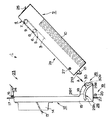
図1は、1枚エスクロ式の紙幣処理装置1の概念側面図である。
この発明の紙幣処理装置1は、図1で示すように、略矩形状の筐体からなる装置本体2と、装置本体2の正面2a全体を覆うフロントカバー12と、装置本体2をフロントカバー12に対し回動自在に支承するとともに、装置本体2をフロントカバー12に対し着脱自在に支承する支承手段19と、該支承手段19により支承された装置本体2をフロントカバー12に位置決め支承させるラッチ手段23と、フロントカバー12に対する装置本体2の回動角度を調整する回動ストッパー手段26とから構成されている。
【0010】
このうち、略矩形状の筐体からなる装置本体2は、一点鎖線で示す紙幣搬送路3であって、紙幣1枚をその途中で一時保留する1枚保留機能を有する紙幣搬送路3と、該紙幣搬送路3に沿って挿入紙幣を搬送する紙幣搬送手段4と、この紙幣搬送手段4を駆動する図示せぬ駆動モータと、該駆動モータの駆動力を紙幣搬送手段4の下プーリ8に伝達する図示せぬ動力伝達手段と、前記紙幣搬送路3を介し搬送された紙幣の真偽を判別する図示せぬ紙幣識別手段と、該紙幣搬送路3の下流に配設され、真券と判断された紙幣を貯留するスタッカ10とから構成されている。
【0011】
このうちの紙幣搬送手段4は、上、下プーリ7、8とこの各プーリ7、8間に巻回された搬送ベルト9からなり、このうち、上、下プーリ7、8は支持板6に支承され、さらにこの支持板6は軸5を介し装置本体2の正面2a側に向け回動自在に支承されている。
なお、この紙幣搬送手段4の搬送ベルト9には図示せぬアイドルローラが圧接し、下プーリ8に動力が伝達されると、下プーリ8に従動して搬送ベルト9が一方向または他方向に回転する。このように搬送ベルト9が一方向または他方向に回転すると、図示せぬアイドルローラが搬送ベルト9の回転に従動し、挿入紙幣を当該搬送ベルト9とアイドルローラとの間に把持して搬送する。
なお、上、下プーリ7、8を支承する支持板6は、図1の初期位置では、当該支持板6と装置本体2との間に介在された図示せぬラッチ手段により装置本体2の上段に位置決め支承されている。
【0012】
また、装置本体2の正面2aを覆うフロントカバー12は、紙幣搬送路3に連通する紙幣挿入口13を形成したフロントマスク14と、該フロントマスク14をその正面に固着し、背面で装置本体2の正面2a全体を覆う断面略コの字形状の枠体15とから構成されている。
なお、このフロントカバー12の枠体15には、その上端に第2の軸16を支承した取っ手17が延設されており、また下端には幅方向へ向け互いに対向するように一対の舌片18が形成されている。
【0013】
また、装置本体2をフロントカバー12に対し着脱自在に支承する支承手段19は、フロントカバー12の下端に差し渡された第1の軸20と、装置本体2の下端に配設され、前記第1の軸20に係合する第1の係合部材21とから構成されている。
このうち、第1の軸20は、フロントカバー12の下端から延設された舌片に固着された一対のリブ22間に差し渡されて支承されている。また、第1の係合部材21には、装置本体2の下端に配設されたU字形状の切り欠き部材であって、前記装置本体2の前記正面2a側で前記第1の軸20に係合する円弧形状の切り欠21aが形成されている。
このような支承手段19によれば、第1の固着リブ22に差し渡された第1の軸20に、第1の係合部材21の円弧形状の切り欠21aを係合することにより、装置本体2をフロントカバー12に対し着脱自在、かつ回動自在に支承することができることとなる。
【0014】
また、ラッチ手段23は、フロントカバー12の上端で、第2の軸16を介しフロントカバー12の枠体15に回動自在に支承されている係合爪24と、装置本体2の上端に配設され、前記係合爪24に係合する第2の係合部材25とから構成される。
なお、図1の初期位置では、このラッチ手段23により装置本体2はフロントカバー12に位置決め支承されている。
また、回動ストッパー手段26は、装置本体2の下端に突設された第3の軸27と、該第3の軸27が嵌挿する円弧形状の回動用案内溝28とから構成され、この回動用案内溝28は、枠体15の舌片18に形成されている。
また、回動用案内溝28を形成した舌片18の一部には、フロントカバー12に装置本体2を着脱する際に、第3の軸27を案内する一端開放の切り欠き30が形成されている。
【0015】
このような紙幣処理装置1によると、紙幣が紙幣挿入口13から挿入されたことが図示せぬ挿入センサにより検出されると、図示せぬ駆動モータが駆動し、該駆動モータの駆動力は、装置本体2の動力伝達手段を介して下プーリ8に伝達され、紙幣搬送手段4の搬送ベルト9が時計方向に回転駆動する。この搬送ベルト9の回転駆動により、挿入紙幣は紙幣搬送手段4の搬送ベルト9と図示せぬ前記アイドルローラに挟持され、紙幣搬送路3に沿って下流に搬送される。その後図示せぬ紙幣識別手段により紙幣の真偽が判別され、偽券と判断された場合は、駆動モータが逆回転して搬送ベルト9を反転させ、当該偽券と判断された挿入紙幣を紙幣挿入口13から返却する。
また、挿入紙幣が図示せぬ紙幣識別手段により真券と判断された場合は、その検出信号に基づき搬送ベルト9は時計方向の回転を維持するので、紙幣は、さらに紙幣搬送路3下流に搬送され、その紙幣搬送路3の途中で一時保留される。 次に、図示せぬ制御手段の商品の払い出しの完了信号に基づき駆動モータが駆動されると、紙幣1枚保留状態が解除される。これにより、搬送ベルト9が時計方向に再回転し、保留されていた紙幣は、さらに下流の紙幣搬送路3に沿って搬送され、しかる後、装置本体2の下方のスタッカ10内に積載収容される。
【0016】
次に、上述した紙幣処理装置1のフロントカバー12と装置本体2の着脱動作について説明する。
図2乃至図6は、この紙幣処理装置1のフロントカバー12と装置本体2の着脱の手順を示す概念側面図であり、図1と同一部分を同一符号で示す。
【0017】
上述した紙幣処理装置1によると、図2のように離脱された装置本体2をフロントカバー12に装着する場合は、図2の矢印Aのように、装置本体2の側方に突設された第3の軸27をフロントカバー12の切り欠き30に嵌挿するとともに、図3で示すように第3の軸27が切り欠き30の下方にある回動用案内溝28に当接するまで装置本体2を切り欠き30に沿って移動する。
そして、装置本体2を第3の軸27を中心に時計方向に回転させるとともに、図3の矢印Bで示すように、回動用案内溝28に当接した第3の軸27が回動用案内溝28の下端28aに当接するまで装置本体2を回動用案内溝28の内側28bに沿って移動し、その後、図4で示すように、支承手段19の第1の軸20と第1の係合部材21とを係合させる。
次に、図4の矢印Cのように装置本体2を第1の軸20を中心に反時計方向に回転し、ラッチ手段23の係合爪24を第2の軸16を中心に反時計方向に回転して装置本体2の第2の係合部材25と係合させると、図1で示すように、装置本体2をフロントカバー12に装着することができる。
【0018】
また、図1で示す紙幣処理装置1のフロントカバー12と、装置本体2を離脱する場合は、図5で示すようにラッチ手段23の係合爪24を第2の軸16を中心に反時計方向に回転して、装置本体2の第2の係合部材25との係合を解除するとともに、図5で示す矢印Dのように装置本体2を第1の軸20を中心に時計方向に回転させる。
なお、第3の軸27は、図4で示すように、回動用案内溝28の下端28aに当接するまで、回動用案内溝28に沿って下方に移動する。また、このとき、紙幣搬送手段4が配設されている装置本体2の正面2a上方に紙幣搬送手段4の開放スペースが形成されるから、第4の軸5を中心に紙幣搬送手段4の支持板6を反時計方向に回転させると、紙幣搬送手段4の搬送ベルト9の交換、または図示せぬ紙幣識別手段の清掃を行うスペースが形成され、このスペースを利用して紙幣搬送手段4の搬送ベルト9の交換、または図示せぬ紙幣識別手段の清掃を行うことが可能である。
また、図4で示すように、回動ストッパー手段26により装置本体2の回動は制限されるため、オペレーターは紙幣搬送手段4の搬送ベルト9の交換、または紙幣識別手段の清掃の際にも装置本体2を支える必要はない。
【0019】
次に、図6で示すように、回動用案内溝28の下端28aに当接した第3の軸27を中心に、装置本体2を時計方向に回転するとともに、第1の軸20と第1の係合部材21との係合を解除し、その後、第3の軸27が切り欠き30の縁30aに当接するまで、図6で示す矢印Fのように、装置本体2を回動用案内溝28の外側28cに沿って移動し、さらに切り欠き30の縁30aに当接した第3の軸27が、図3で示す矢印Gのように、切り欠き30から脱出するまで、装置本体2を切り欠き30に沿って移動すると、図2で示すようにフロントカバー12から装置本体2を離脱することができる。
【0020】
このように、この発明の紙幣処理装置1では、装置本体2をフロントカバー12に対し回動自在に支承するとともに、装置本体2をフロントカバー12に対し着脱自在に係合する支承手段19を具備するようにしたから、装置本体2に配設されている紙幣搬送手段4、図示せぬ駆動モータ、図示せぬ動力伝達手段等の故障による修理や保守点検の際には、装置本体2を簡単に離脱することができ、さらに修理または保守点検がされた装置本体2を簡単にフロントカバー12に装着することができる。
【0021】
したがって、この発明の紙幣処理装置1を装着した自動販売機では、自動販売機の一定位置に取り付けられた紙幣処理装置1全体を工具等を使用して自動販売機本体から離脱することなく、自動販売機の一定位置に取り付けられたフロントカバー12から装置本体2のみを取り外して、その修理または保守点検を簡単に行うことができることとなる。
【0022】
また、この発明の紙幣処理装置1では、支承手段19を介し装置本体2をフロントカバー12に対し回動自在に支承するとともに、フロントカバー12に対し装置本体2を着脱自在に係合させるようにしたから、異なるタイプの装置本体であっても、同一構造の支承手段19を有する装置本体であれば、その装置本体をフロントカバー12に対し簡単に交換することができ、従来のようにタイプのことなる紙幣処理装置を交換する場合は、紙幣挿入口13を有するフロントカバー12を含め紙幣処理装置1全体を交換する作業を行うことなく、タイプの異なる装置本体2のみを交換することにより、紙幣処理装置1を異なるタイプのものに変更することができる。
【0023】
図1と同一部分を同一符号で示す図7は、各種タイプの紙幣処理装置を構成する各種タイプの装置本体42、52、62を示す概念側面図である。
図7(a)で示す装置本体42は、高さ方向に長く、紙幣搬送距離が延長されその間に紙幣を3枚一時保留することができる紙幣搬送路43と、紙幣搬送路43に沿って紙幣を搬送する紙幣搬送手段44とから構成される装置本体42である。
図7(b)で示す装置本体52は、奥行き方向に長く、紙幣搬送距離が延長されその間に紙幣を3枚一時保留することができる紙幣搬送路53と、該紙幣搬送路53に沿って紙幣を搬送する紙幣搬送手段54とから構成される装置本体52である。
なお、上述した各装置本体42、52はその下端の同一位置に同一サイズ、同一構造の支承手段19が形成されている。
【0024】
上述した各種タイプの装置本体42、52がオプションとしてある場合、例えば、図1で示す1枚エスクロ式の紙幣処理装置1を、紙幣3枚を保留して商品が払い出された後に、その保留した紙幣を、スタッカ内に貯留する、いわゆる3枚エスクロ式の紙幣処理装置に変更しようとする際は、図1のフロントカバー12をそのままの状態に維持したまま、装置本体2のみをフロントカバー12から離脱し、該フロントカバー12に、図7(a)、または図7(b)で示す紙幣3枚保留式装置本体42、52を、前述した手順で装着すれば、図1、図7(a)と同一部分を同一符号で示す図8、または図1、図7(b)と同一部分を同一符号で示す図9のように、それぞれ、3枚エスクロ式の紙幣処理装置41、51に交換することができることとなる。
【0025】
一方、図7(c)は、スタッカ10内に収容された紙幣を払い出すピックアップローラ66と、紙幣搬送手段64とからなる紙幣払い出し手段65を具えた装置本体62である。
なお、上述した各装置本体42、52はその下端の同一位置に同一サイズ、同一構造の支承手段19が形成されている。また、符号63は紙幣搬送路を示している。
【0026】
このようなタイプの装置本体62がオプションとしてある場合、例えば、図1で示す1枚エスクロ式の紙幣処理装置1を、紙幣払い出し式の紙幣処理装置に変更しようとする場合も、図1の装置本体2をフロントカバー12から離脱し、該フロントカバー12に、図7(c)で示す紙幣払い出し手段65を配設した装置本体62を、上述した手順で装着すれば、図1、図7(c)と同一部分を同一符号で示す図10のように、払い出し式の紙幣処理装置61に簡単に交換することができることとなる。
【0027】
従って、この発明の紙幣処理装置を装着した自動販売機では、使用目的に応じオプションとして設けられた各種装置本体2、42、52、62を自動販売機の一定位置に取り付けられた同一構造のフロントマスク12に選択的に装着することができるので、使用目的に応じた自動販売機を簡単に提供することができることとなる。
【0028】
なお、この実施例の紙幣処理装置1では回動ストッパー手段26を配設したが、これに限定するものではなく、たとえば、紙幣処理装置1を回動ストッパー手段26を配設しないで構成してもよい。
【0029】
【発明の効果】
以上説明したように、この発明の紙幣処理装置では、装置本体をフロントカバーに対し回動自在に支承するとともに、装置本体をフロントカバーに対し着脱自在に係合する支承手段を具え、該支承手段により、異なるタイプの前記装置本体を前記フロントカバーに対し回動自在に支承させるとともに、前記装置本体を前記フロントカバーに対し着脱自在に支承させるようにしたから、従来のように紙幣挿入口を有するフロントカバーを含め、紙幣処理装置全体を交換する作業を行うことなく、装置本体のみを交換することができ、これにより紙幣処理装置を異なるタイプのものに変更することができる。したがって、この発明の紙幣処理装置では、各種タイプの装置本体を自動販売機の一定位置に取り付けられた同一のフロントマスクに着脱自在に装着することができ、このため異なるタイプの紙幣処理装置を自動販売機、両替機、またはパチンコ玉貸機やメタル貸機等のサービス機器に簡単に設置することができる。
【0030】
また、この発明の紙幣処理装置では、装置本体をフロントカバーに対し回動自在に支承するとともに、装置本体をフロントカバーに対し着脱自在に係合する支承手段を具備するようにしたから、装置本体に配設されている紙幣搬送手段、図示せぬ駆動モータ、図示せぬ動力伝達手段等の故障による修理や保守点検の際には、装置本体を簡単に離脱することができ、さらに修理または保守点検がされた装置本体を、装置本体が離脱されたフロントカバーに装着することができる。
【0031】
したがって、この発明の紙幣処理装置からなる自動販売機では、自動販売機の一定位置に取り付けられた紙幣処理装置を工具等を使用して自動販売機本体から離脱することなく、紙幣処理装置の修理または保守点検を簡単に行うことができ、これにより自動販売機、両替機、またはパチンコ玉貸機やメタル貸機等のサービス機器の修理、保守点検の効率化を図ることができる。
【図面の簡単な説明】
【図1】図1は、この発明の紙幣処理装置の概念平面図。
【図2】図2は、この発明の紙幣処理装置のフロントカバーと装置本体の着脱の手順を示す概念平面図。
【図3】図3は、この発明の紙幣処理装置のフロントカバーと装置本体の着脱の手順を示す概念平面図。
【図4】図4は、この発明の紙幣処理装置のフロントカバーと装置本体の着脱の手順を示す概念平面図。
【図5】図5は、この発明の紙幣処理装置のフロントカバーと装置本体の着脱の手順を示す概念平面図。
【図6】図6は、この発明の紙幣処理装置のフロントカバーと装置本体の着脱の手順を示す概念平面図。
【図7】図7は、第2乃至第4の実施例の紙幣処理装置を構成する装置本体の概念平面図。
【図8】図8は、図7(a)で示す装置本体から構成される第2の実施例の紙幣処理装置の概念平面図。
【図9】図9は、図7(b)で示す装置本体から構成される第3の実施例の紙幣処理装置の概念平面図。
【図10】図10は、図7(c)で示す装置本体から構成される第4の実施例の紙幣処理装置の概念平面図。
【符号の説明】
1、41、51、61…紙幣処理装置
3、43、53、63…紙幣搬送路
4、44、54、64…紙幣搬送手段
10…スタッカ
2、42、52、62…装置本体
13…紙幣挿入口
12…フロントカバー
19…支承手段
20…第1の軸
21…第1の係合部材
65…紙幣払い出し手段
23…ラッチ手段[0001]
TECHNICAL FIELD OF THE INVENTION
The present invention relates to an improvement in a banknote handling apparatus used for a vending machine, a currency exchange machine, or a service device such as a pachinko ball lending machine or a metal lending machine.
[0002]
[Prior art]
Generally, service machines such as vending machines, currency exchange machines, pachinko ball lending machines and metal lending machines include a so-called bill processing device that determines the authenticity of inserted bills and stores the genuine bills in a stacker. Some are arranged.
[0003]
Various types of banknote handling devices are prepared.
For example, there is a so-called one-sheet escrow type banknote handling device that holds one banknote in a banknote transport path and stores the stored banknote in a stacker after the product is paid out. There is a so-called three-escrow type banknote processing device that stores the stored banknotes in a stacker after the products are stored and paid out.
Furthermore, there is a so-called payout type banknote handling apparatus that can pay out the banknotes stored in the stacker from the banknote transfer port.
[0004]
On the other hand, the sizes of these various types of banknote handling apparatuses are different depending on their functions.
[0005]
In addition, a front cover having a bill insertion slot provided in these various types of bill processing devices, and the above-described bill conveyance, bill authenticity judgment, bill temporary holding, bill stacking, bill payout from a stacker, and the like. The apparatus main body having the various functions described above has a structure in which it is integrally fixed.
[0006]
[Problems to be solved by the invention]
By the way, according to the above-mentioned conventional banknote handling machine, when it is going to change the banknote handling machine attached to the service equipment to a different type, for example, from a single-sheet escrow-type banknote handling machine to a three-sheet escrow-type banknote When changing to a processing device, the entire size of the banknote processing device is different, so the front door, etc. of the service equipment to which the banknote processing device is attached must be replaced with a device that supports various types of banknote processing devices. And the operation is complicated.
[0007]
The present invention has been made in view of the above circumstances, and an object of the present invention is to provide a banknote processing apparatus that can easily exchange different types of banknote processing apparatuses.
[0008]
[Means for Solving the Problems]
In order to solve the above-described problems, the present invention has at least a bill transport path, a bill transport unit that transports bills along the bill transport path, and a stacker that holds a genuine bill inside, and the bill transport An apparatus body consisting of a housing configured to store the genuine bill in the stacker by judging the authenticity of the inserted bill transported through the road, and a bill insertion slot communicating with the bill transport path are formed, A bill processing device having at least a front cover for covering a front surface of the device main body, a support for rotatably supporting the device main body with respect to the front cover and removably supporting the device main body with respect to the front cover. Means for rotatably supporting the apparatus main body of a different type with respect to the front cover by the support means, and connecting the apparatus main body to the front cover. And so as to freely supported detachably to chromatography.
[0009]
BEST MODE FOR CARRYING OUT THE INVENTION
Hereinafter, an embodiment of the bill processing apparatus according to the present invention will be described in detail.
As a first embodiment of this embodiment, a so-called one-sheet escrow type in which one banknote is temporarily stored in a banknote transport path and the stored banknotes are stored in a stacker after the commodity is paid out, is provided. Will be described in detail.
FIG. 1 is a conceptual side view of a single-sheet escrow type
As shown in FIG. 1, the banknote handling
[0010]
Among these, the apparatus
[0011]
The bill transporting means 4 includes upper and
An idle roller (not shown) is pressed against the
In the initial position shown in FIG. 1, the
[0012]
Further, a
The
[0013]
Further, a support means 19 for detachably supporting the apparatus
The
According to such a bearing means 19, by engaging the arc-
[0014]
The latch means 23 is provided at an upper end of the
In the initial position shown in FIG. 1, the
The rotation stopper means 26 includes a
A
[0015]
According to such a
Further, when the inserted bill is judged as a genuine bill by a bill discriminating means (not shown), the
[0016]
Next, the attachment / detachment operation of the
2 to 6 are conceptual side views showing a procedure for attaching and detaching the
[0017]
According to the
Then, the device
Next, as shown by an arrow C in FIG. 4, the apparatus
[0018]
When the
As shown in FIG. 4, the
Further, as shown in FIG. 4, since the rotation of the apparatus
[0019]
Next, as shown in FIG. 6, the apparatus
[0020]
As described above, the
[0021]
Therefore, in the vending machine equipped with the
[0022]
In the
[0023]
FIG. 7 showing the same parts as those in FIG. 1 by the same reference numerals is a conceptual side view showing various types of apparatus
The device
The device main body 52 shown in FIG. 7B is long in the depth direction, has a long bill transporting distance, and can temporarily hold three bills in the meantime. And a bill transporting means 54 for transporting the paper.
Each of the above-described device
[0024]
When the various types of apparatus
[0025]
On the other hand, FIG. 7C illustrates an apparatus
Each of the above-described device
[0026]
When the device
[0027]
Therefore, in a vending machine equipped with the banknote handling machine of the present invention, a front device having the same structure in which various device
[0028]
In addition, in the
[0029]
【The invention's effect】
As described above, the banknote handling apparatus according to the present invention includes the support means for rotatably supporting the apparatus main body with respect to the front cover, and the support means for detachably engaging the apparatus main body with the front cover. Thereby, the device main body of a different type is rotatably supported on the front cover, and the device main body is removably supported on the front cover. It is possible to replace only the main body of the bill processing apparatus without performing the operation of replacing the entire bill processing apparatus including the front cover, thereby changing the bill processing apparatus to a different type. Therefore, in the banknote processing apparatus of the present invention, various types of apparatus main bodies can be removably mounted on the same front mask attached to a fixed position of the vending machine, so that different types of banknote processing apparatuses can be automatically mounted. It can be easily installed in vending machines, currency exchange machines, or service equipment such as pachinko ball rental machines and metal rental machines.
[0030]
Further, in the banknote handling apparatus of the present invention, the apparatus main body is rotatably supported on the front cover, and the supporting means for detachably engaging the apparatus main body with the front cover is provided. The device main body can be easily detached during repair or maintenance due to a failure of a bill transporting means, a driving motor (not shown), a power transmission means (not shown), etc. provided in The inspected apparatus main body can be mounted on the front cover from which the apparatus main body has been detached.
[0031]
Therefore, in the vending machine including the bill processing device of the present invention, the bill processing device attached to a fixed position of the vending machine can be repaired without detaching from the vending machine main body using a tool or the like. Alternatively, maintenance and inspection can be easily performed, thereby improving the efficiency of repair and maintenance and inspection of service equipment such as vending machines, currency exchange machines, pachinko ball lending machines, metal lending machines, and the like.
[Brief description of the drawings]
FIG. 1 is a conceptual plan view of a bill processing device of the present invention.
FIG. 2 is a conceptual plan view showing a procedure for attaching and detaching a front cover and an apparatus main body of the banknote handling apparatus of the present invention.
FIG. 3 is a conceptual plan view showing a procedure for attaching and detaching a front cover and an apparatus main body of the banknote handling apparatus of the present invention.
FIG. 4 is a conceptual plan view showing a procedure for attaching and detaching a front cover and an apparatus main body of the banknote handling apparatus of the present invention.
FIG. 5 is a conceptual plan view showing a procedure of attaching and detaching a front cover and an apparatus main body of the banknote handling apparatus of the present invention.
FIG. 6 is a conceptual plan view showing a procedure for attaching and detaching a front cover and an apparatus main body of the banknote handling apparatus of the present invention.
FIG. 7 is a conceptual plan view of an apparatus main body constituting the banknote processing apparatus of the second to fourth embodiments.
FIG. 8 is a conceptual plan view of a bill processing apparatus according to a second embodiment, which is constituted by the apparatus main body shown in FIG. 7A.
FIG. 9 is a conceptual plan view of a bill processing apparatus according to a third embodiment constituted by the apparatus main body shown in FIG. 7B.
FIG. 10 is a conceptual plan view of a bill processing apparatus according to a fourth embodiment, which is configured by the apparatus main body shown in FIG. 7C.
[Explanation of symbols]
1, 41, 51, 61:
Claims (6)
前記装置本体を前記フロントカバーに対し回動自在に支承するとともに、前記装置本体を前記フロントカバーに対し着脱自在に支承する支承手段を具え、該支承手段により、異なるタイプの前記装置本体を前記フロントカバーに対し回動自在に支承させるとともに、前記装置本体を前記フロントカバーに対し着脱自在に支承させるようにしたことを特徴とする紙幣処理装置。A banknote transport path, a banknote transporting unit that transports banknotes along the banknote transport path, and at least a stacker that holds a genuine note inside, and verifies the authenticity of inserted banknotes transported through the banknote transport path. The apparatus body consisting of a housing that discriminates and stores genuine bills in the stacker, and a bill insertion slot communicating with the bill conveyance path are formed, and at least a front cover that covers the front of the apparatus body In a banknote handling machine having
The apparatus main body includes a support means for rotatably supporting the apparatus body with respect to the front cover, and a support means for supporting the apparatus body in a detachable manner with respect to the front cover. A bill processing device, wherein the device is rotatably supported on a cover and the device main body is removably supported on the front cover.
Priority Applications (3)
| Application Number | Priority Date | Filing Date | Title |
|---|---|---|---|
| JP24117197A JP3597022B2 (en) | 1997-09-05 | 1997-09-05 | Banknote handling equipment |
| US09/140,287 US6158565A (en) | 1997-08-28 | 1998-08-25 | Bill processor |
| KR1019980034826A KR100300641B1 (en) | 1997-08-28 | 1998-08-27 | Bill processor |
Applications Claiming Priority (1)
| Application Number | Priority Date | Filing Date | Title |
|---|---|---|---|
| JP24117197A JP3597022B2 (en) | 1997-09-05 | 1997-09-05 | Banknote handling equipment |
Publications (2)
| Publication Number | Publication Date |
|---|---|
| JPH1186071A JPH1186071A (en) | 1999-03-30 |
| JP3597022B2 true JP3597022B2 (en) | 2004-12-02 |
Family
ID=17070309
Family Applications (1)
| Application Number | Title | Priority Date | Filing Date |
|---|---|---|---|
| JP24117197A Expired - Lifetime JP3597022B2 (en) | 1997-08-28 | 1997-09-05 | Banknote handling equipment |
Country Status (1)
| Country | Link |
|---|---|
| JP (1) | JP3597022B2 (en) |
Families Citing this family (3)
| Publication number | Priority date | Publication date | Assignee | Title |
|---|---|---|---|---|
| JP2002092691A (en) * | 2000-09-19 | 2002-03-29 | Sanden Corp | Paper sheet housing device |
| JP2006079187A (en) * | 2004-09-07 | 2006-03-23 | World Techno:Kk | Processor for print paper sheet |
| JP6070476B2 (en) * | 2013-08-20 | 2017-02-01 | 沖電気工業株式会社 | Rotating device and medium transaction device |
-
1997
- 1997-09-05 JP JP24117197A patent/JP3597022B2/en not_active Expired - Lifetime
Also Published As
| Publication number | Publication date |
|---|---|
| JPH1186071A (en) | 1999-03-30 |
Similar Documents
| Publication | Publication Date | Title |
|---|---|---|
| JP4257207B2 (en) | Paper sheet handling equipment | |
| EP2549448B1 (en) | BIll and cheque acceptor | |
| JP2004240904A (en) | Bill depositing and dispensing device | |
| JP6445727B1 (en) | Paper feeding tray, paper feeding device, and reflux paper sheet processing device | |
| KR100300641B1 (en) | Bill processor | |
| KR20140088946A (en) | Cassette for deposit and withdrawal of checks and automatic teller machine having the same | |
| JPH06325241A (en) | Paper money processor | |
| EP1739636B1 (en) | Paper money input and output device | |
| KR101016245B1 (en) | Apparatus of drawing bills in a cash transaction machine | |
| EP2400469B1 (en) | Paper sheet handling device | |
| JP3597022B2 (en) | Banknote handling equipment | |
| JPH0766460B2 (en) | Banknote deposit and withdrawal machine | |
| JP6547344B2 (en) | Medium storage and medium handling device | |
| JP4562265B2 (en) | Paper sheet identification storage device | |
| KR101988058B1 (en) | Automated Teller Machine with a structure capable of maintenance easily | |
| JP2001134839A (en) | Paper money receiving/paying-out device | |
| JPS6365994B2 (en) | ||
| JP3579230B2 (en) | Sheet material guiding device | |
| KR200389004Y1 (en) | Apparatus of drawing bills in a cash transaction machine | |
| JP4152763B2 (en) | Paper sheet sorting device | |
| WO2017221530A1 (en) | Medium processing device and medium transaction device | |
| JPS6337066A (en) | Paper sheet handler | |
| KR100603522B1 (en) | Delivery type customer access module | |
| JP2543178B2 (en) | Banknote automatic deposit / withdrawal device | |
| JP4270385B2 (en) | Banknote handling equipment |
Legal Events
| Date | Code | Title | Description |
|---|---|---|---|
| A977 | Report on retrieval |
Free format text: JAPANESE INTERMEDIATE CODE: A971007 Effective date: 20040326 |
|
| A131 | Notification of reasons for refusal |
Free format text: JAPANESE INTERMEDIATE CODE: A131 Effective date: 20040427 |
|
| A521 | Written amendment |
Free format text: JAPANESE INTERMEDIATE CODE: A523 Effective date: 20040623 |
|
| TRDD | Decision of grant or rejection written | ||
| A01 | Written decision to grant a patent or to grant a registration (utility model) |
Free format text: JAPANESE INTERMEDIATE CODE: A01 Effective date: 20040810 |
|
| A521 | Written amendment |
Free format text: JAPANESE INTERMEDIATE CODE: A523 Effective date: 20040623 |
|
| A61 | First payment of annual fees (during grant procedure) |
Free format text: JAPANESE INTERMEDIATE CODE: A61 Effective date: 20040907 |
|
| R150 | Certificate of patent or registration of utility model |
Free format text: JAPANESE INTERMEDIATE CODE: R150 |
|
| S111 | Request for change of ownership or part of ownership |
Free format text: JAPANESE INTERMEDIATE CODE: R313111 |
|
| FPAY | Renewal fee payment (event date is renewal date of database) |
Free format text: PAYMENT UNTIL: 20070917 Year of fee payment: 3 |
|
| R350 | Written notification of registration of transfer |
Free format text: JAPANESE INTERMEDIATE CODE: R350 |
|
| FPAY | Renewal fee payment (event date is renewal date of database) |
Free format text: PAYMENT UNTIL: 20080917 Year of fee payment: 4 |
|
| FPAY | Renewal fee payment (event date is renewal date of database) |
Free format text: PAYMENT UNTIL: 20090917 Year of fee payment: 5 |
|
| FPAY | Renewal fee payment (event date is renewal date of database) |
Free format text: PAYMENT UNTIL: 20100917 Year of fee payment: 6 |
|
| FPAY | Renewal fee payment (event date is renewal date of database) |
Free format text: PAYMENT UNTIL: 20100917 Year of fee payment: 6 |
|
| FPAY | Renewal fee payment (event date is renewal date of database) |
Free format text: PAYMENT UNTIL: 20110917 Year of fee payment: 7 |
|
| FPAY | Renewal fee payment (event date is renewal date of database) |
Free format text: PAYMENT UNTIL: 20120917 Year of fee payment: 8 |