JP3588540B2 - GUI creation support device, GUI creation support method, and recording medium recording GUI creation support program - Google Patents
GUI creation support device, GUI creation support method, and recording medium recording GUI creation support program Download PDFInfo
- Publication number
- JP3588540B2 JP3588540B2 JP26436297A JP26436297A JP3588540B2 JP 3588540 B2 JP3588540 B2 JP 3588540B2 JP 26436297 A JP26436297 A JP 26436297A JP 26436297 A JP26436297 A JP 26436297A JP 3588540 B2 JP3588540 B2 JP 3588540B2
- Authority
- JP
- Japan
- Prior art keywords
- gui
- component
- display
- unit
- creation support
- Prior art date
- Legal status (The legal status is an assumption and is not a legal conclusion. Google has not performed a legal analysis and makes no representation as to the accuracy of the status listed.)
- Expired - Fee Related
Links
Images


Description
【0001】
【発明の属する技術分野】
本発明は、コンピュータアプリケーションプログラム等のグラフィカルユーザインターフェース(以下「GUI」という)の作成を支援するGUI作成支援装置、GUI作成支援方法及びGUI作成支援のプログラムを記録した記録媒体に関する。
【0002】
【従来の技術】
GUIの設計・作成には、GUI作成支援装置(GUIビルダ)を用いる場合が多い。
【0003】
一般的なGUI作成支援装置では、自由にサイズを変更できるウィンドウ枠内に、GUI部品と呼ばれるボタンやリストをパレットの中から選択し、配置することによってGUIの設計や作成を行う。この作業は、GUIの設計者が行い、GUIの表示画面を利用して計算機の利用者と計算機の間でやりとりされるデータを具体的なGUIの表示画面として表現して行く。このようなGUI作成支援装置を利用したGUIの設計・作成では、以下のような問題がある。
【0004】
すなわち、GUI作成支援装置を利用したGUIの設計・作成は、絵を描くような方法で簡単にGUIの画面設計を行うことができるという利点がある。しかしながら、この利点が逆に、最終的な完成状態をイメージせずに、GUIを設計・作成してしまい、後で手戻り工程が発生するという問題を引き起こしている。つまり、設計過程における部品の追加や機能の変更がたびたび生じている。特に、候補から選択して入力するようなデータの場合、将来、候補が追加される可能性がある。GUI部品の中には、固定候補からの選択用だけに提供されているものと候補の追加を考慮したものがあり、候補を固定だと考えて固定候補からの選択用の部品を利用している場合は、候補が追加になるとGUIの画面を作り直さなければならない。従って、設計者は、具体的にどの部品をどのように使用するかを考慮しながら、最終的な完成状態をイメージしつつ、設計・作成を行わなければならなかった。
【0005】
例えば、複数の項目の中から1つの項目を選択するようなGUIを作成する場合には、プルダウンメニュー、排他的ボタン、リストボックス等の表現方法(部品)が用意されている。このような場合、どの方法に従うことがよいのかは、その操作場面等により異なり、さらには、利用者や設計者の好みによっても異なる。 かかる場合に、従来のGUI作成支援装置では、ある表現方法から他の表現方法の変更を行う手段に乏しく、一旦、ある部品で表現すると決めてしまった場合には、これを他の部品に置き換えるためには、該当するGUI画面を再構築する場合と同等の作業を必要としていた。
【0006】
また、実際のシステムを作成する前に、その外観や挙動を確認するためのモックアップを作成することが一般的に行われている。しかしながら、モックアップを作成すること自体が非常に煩わしく、不便であった。
【0007】
【発明が解決しようとする課題】
本発明は、上記課題を解決するためになされたもので、操作性及び保守性に優れたGUIの対話画面を設計・作成することができるGUI作成支援装置、GUI作成支援方法及びGUI作成支援のプログラムを記録した記録媒体を提供することを目的とする。
【0008】
さらに、本発明は、変換対象となるGUI部品が現在どの部品であるかという情報を考慮したGUI作成支援装置、GUI作成支援方法及びGUI作成支援のプログラムを記録した記録媒体を提供することを目的とする。
【0009】
また、本発明は、変換対象となるGUI部品の現在の配置状況を考慮したGUI作成支援装置、GUI作成支援方法及びGUI作成支援のプログラムを記録した記録媒体を提供することを目的とする。
【0010】
【課題を解決するための手段】
かかる課題を解決するため、請求項1記載に係る本発明は、機能の内容を示す機能情報と表示画面への表示内容を示す表示情報とを含む表示部品データを格納する記憶手段と、ユーザからの選択指示および入力指示に基づいて、記憶手段から表示部品データを選択するとともに該選択された表示部品データの表示情報として入力指示の内容を設定する設定入力手段と、ユーザからの変換指示に基づいて、選択された表示部品データの機能情報に代えて変換されるべき機能情報候補を、記憶手段に格納された表示部品データの機能情報の中から選択する変換候補選択手段と、設定された表示情報に基づいて、選択された変換されるべき機能情報候補に優先順位情報を付加する優先情報付加手段と、優先情報に基づいて機能情報候補を表示画面に表示する候補表示手段とを具備することを特徴とする。
【0011】
請求項2記載に係る本発明は、機能の内容を示す機能情報を含む表示部品データを格納する記憶手段と、ユーザからの選択指示に基づいて、記憶手段から表示部品データを選択する選択入力手段と、選択された表示部品データの機能情報に基づいて、選択された表示部品データに代えて変換されるべき表示部品データ候補を記憶手段から選択して、表示画面に表示する変換候補表示手段とを具備することを特徴とする。
【0027】
本発明によれば、例えば設計中のGUIの中から、GUIオブジェクト(表示部品)を1つ選び、変換キーを押すと、現在の表示部品が他の表示部品に変換される。例えば、「OK」と書かれた「ラベル」を選択して変換すると、「OK」と書かれた「テキストフィールド」に変換される。そして、再度変換キーを押すと
「OK」と書かれた「ボタン」に変換される。さらに変換キーを押すと、「OK」と書かれたオプションボタンに変換される。選択されているオブジェクトが1つの場合には、例えば、「ラベル」、「テキストフィールド」、「ボタン」、「チェックボックス」のオブジェクトが変換候補となる。
【0028】
同様に複数のGUIオブジェクトを選択してから変換した場合にも変換を行う。変換候補は、例えば、「ラベルの集合」、「テキストフィールドの集合」、「複数行のテキストフィールド」、「コマンドボタンの集合」、「チェックボックスの集合」、「オプションボタンの集合」、「リストボックス」、「コンボボックス」、「ドロップダウンリストボックス」、「タブダイアログ」、「ツリービュー」のオブジェクトが変換候補となる。なお、これらの呼び名は変換候補としてあげているものの一例に過ぎない。本発明は、これに限定されるものではない。 このような選択候補の順番は各部品の使用頻度やラベル名により変更や学習が可能である。
【0029】
【発明の実施の形態】
以下、本発明の実施形態を図面に基づき説明する。
【0030】
図1は、本発明の一実施形態に係るGUI作成支援装置の構成を示す図である。同図において、入力部1は、作成しようとするGUIにおいて使用される文字列データやビットマップデータ、および各操作状況に応じたコマンド等を入力するためのものである。この入力部1は、例えば、キーボードおよびマウス等のポインティングデバイスにより実現される。表示部2は、コンピュータが扱うさまざまな内部データ等をユーザに提示するためのものであり、この例では、特に、後述するウィンドウ(Form)やラベル等の表示部品、マウスカーソル等を表示するためのものであり、テキストのみならずグラフィカルな図形等も表示することができる。この表示部2は、いわゆるディスプレイ等により実現される。これら入力部1および表示部2により、ユーザインターフェースを構成する。
【0031】
部品管理部3は、入力部1から入力された各種入力情報等に基づき、表示部2に表示された表示部品等に対応する部品データに関し、種々の管理を行うものである。部品管理部3の詳細は後述する。部品記憶部4は、上記各入力部1により入力された文字列データやビットマップデータを、部品データとして記憶する。変換部5は、ルール記憶部6に記憶されている変換規則や頻度記憶部7に記憶されている変換頻度情報に基づいて、部品管理部3から送出されてきた部品データを変換する。学習部8は、頻度情報について、所定の学習アルゴリズムにより学習を行い、頻度情報記憶部7に記憶された頻度情報を更新する。
【0032】
次に、部品管理部3について、詳細に説明する。
【0033】
図2は、部品管理部3の構成を示す図である。図2において、入力情報解釈部21は、入力部1から送出されてきた入力情報について、コマンドやその他の指示であるか、文字列データまたはビットマップデータであるかを解釈して、その解釈結果に応じて後述する各部にデータないし制御情報等を送出する。このような解釈は、操作状況や入力モードに応じて適宜解釈される。
【0034】
まず、入力情報解釈部21は、文字列データまたはビットマップデータであると解釈した場合、該文字列データ等を部品データ登録部22に送出する。部品データ登録部22は、送出されてきた文字列データやビットマップデータを部品データとして、部品記憶部4に送出する。
【0035】
また、入力情報解釈部21が、部品選択指示であると解釈した場合、部品選択部23に、そのときの入力情報を送出する。部品選択部23は、該入力情報に基づいて該当する部品(群)を選択する。すなわち、部品選択部23は、該入力情報を構成する位置情報と、画面データ記憶部24に記憶された画面情報とから、表示部品を選択する。この場合、入力情報に従って複数選択することも可能である。部品選択部23は、表示部品を選択すると、該表示部品に関する情報を、部品データ読み出し部25に送出する。また、部品選択部23は、表示部品が選択されたことをユーザに明示するため、画面データ記憶部24の画面データを更新する。部品データ読み出し部25は、送出されてきた表示部品に関する情報に従って、該当する部品データを部品記憶部4から読み出し、その内容を内部に一時的に保持する。
【0036】
さらに、入力情報解釈部21は、部品変換指示であると解釈した場合、変換指示部26に、そのときの入力情報を送出する。変換指示部26は、部品データ読み出し部25に一時的に保持されている部品データを、部品データ読み出し部25から読み出し、これを変換部5に送出する。つまり、この送出される部品データは、部品選択部23により選択された表示部品に対応したものとなる。選択された部品データ(群)は、変換部5において、ルール記憶部6に記憶された変換ルールおよび頻度情報記憶部7に記憶された頻度情報に基づき候補一覧が作成され、候補選択部27に返されることとなる。候補選択部27は、該候補一覧の中から、選択候補として1つを選択し、該選択候補に基づいて、画面データ記憶部24の内容を書き換える。これにより、表示部2の画面上には、変換結果が表示されることとなる。
【0037】
選択候補の選択は、例えば、候補一覧の先頭から順次選択し、候補一覧のすべてを選択し終えたら、また、先頭の候補を選択するようにする。このような次候補の選択は、入力部1により変換命令が続けて入力された場合に、入力情報解釈部1が次候補選択と解釈して、候補選択部27に変換命令を送出することにより行われる。
【0038】
入力情報解釈部21が、部品選択の解除であると解釈した場合、部品選択部23および候補選択部27に、そのときの入力情報を送出する。部品選択部23は、表示部品が選択解除されたことをユーザに明示するため、画面データ記憶部24の画面データを選択解除が分かる画面データに更新する。一方、候補選択部27は、最終的に選択された表示部品を学習部8に送出する。
【0039】
次に、本発明に係るGUI作成支援装置の操作について、例を用いて説明する。 GUI作成支援装置の起動当初は、表示部2には初期状態として、部品等が全く配置されていないウィンドウ(Form)が表示される。図3は、ウィンドウの初期状態の一例を示す図である。この例では、部品等が全く配置されていない状態を初期状態としたが、例えば、デフォルト部品を予め定義しておき、このデフォルト部品を表示した状態を初期状態とするようにしてもよい。
【0040】
今、入力部1を用いて文字列を5つ入力するものとする。ここでは、「ファイル」、「保存」、「新規保存」、「開く」、「終了」の 5 つ文字列を作成する。例えば、マウス等のポインティングデバイス(図示せず)を用いてウィンドウ上の任意の位置を指示した後、入力部1より所望の文字列を入力し、確定すると、文字列データと予め設定された枠データとが組み合わされた1つの部品データが、部品データ登録部22によって生成される。この部品データは、部品記憶部4に記憶される。
【0041】
図4A及び図4Bは、部品記憶部4に記憶された部品データの一例を示す図である。図4Aに示すように、部品データは、各GUI部品の番号401、要素数402、要素番号403、下位要素数404、文字列405、部品名406、値407、状態408、位置409、大きさ410、下位要素411から構成される。例えば、入力部1によって入力される文字列は、最初は例えば「ラベル」と呼ばれる表現形式として格納されるものとする。「ファイル」という文字列を入力すると、図4Bに示すようなデータが生成され、記憶されることになる。
【0042】
ここで、各項目について、説明する。
【0043】
番号401は、部品を特定するために用いられる部品ごとに与えられた一意な番号である。
【0044】
要素数402は、同じグループ内に含まれる同じ階層にある部品要素の数であり、ここでは、ファイルというラベルが1つしか含まれていないので、要素数は1である。
【0045】
要素番号403は、同じグループに含まれている同じ階層にある要素ごとに与えられる一意な番号である。
【0046】
下位要素数404は、例えば、メニュー部品のように、ある部品と他の部品とが階層関係がある場合、下位に存在する要素数を示す。
【0047】
文字列405は、部品要素が表示する文字列である。
【0048】
部品名406は、部品要素の名前である。
【0049】
値407は、部品要素の値である。例えば、チェックボックスの場合、チェックされていれば1、チェックされていなければ0の値を取る。値を取らない部品の場合には空(null)である。各部品により取り得る値は異なるものとする。
【0050】
状態408は、部品要素の状態である。例えば、ボタンの場合、操作不可の状態ならば「不可」、操作可能ならば「可」の状態を取る。部品により、取り得る状態は異なる。
【0051】
位置409は、ウィンドウ内の部品要素の位置を示す。例えば、ピクセル数により表される。
【0052】
大きさ410は、部品の大きさを示す。
【0053】
下位要素411は、下位にある部品の情報である。下位要素が無い場合には空である。
【0054】
上記5つの文字列を全て入力し終わった状態のウィンドウを図5に示す。同図に示す各ラベルについて上述のような部品データがそれぞれ記憶される。
【0055】
次に、入力部1を用いて、「保存」、「新規保存」、「開く」、「終了」の4つのラベルを選択操作し、ラベル「ファイル」上にドラッグ&ドロップする。この操作状態のウィンドウを図6に示す。すなわち、ユーザが、マウスカーソル等を操作して、表示部2に表示されたウィンドウ上に表示されているラベル(表示部品)に相応する位置で、マウスボタンをクリックして入力情報を与えると、マウスカーソルの位置情報に基づいて対応するラベルが選択されたことを示すマークが表示されるとともに、続くドラッグ&ドロップ等の入力操作が可能となる。なお、ここでは、例えば、SHIFTキーを押しながら、ラベルを順次クリックする等した場合には、複数のラベルが選択できるものとする。そして、マウスカーソルをドラッグ操作して、ラベル「ファイル」とその他選択されたラベル群とを、位置的に重なった状態で、ドロップすると、ウィンドウ上の表示部品は、他の形式の表示部品に変換される。
【0056】
図7は部品管理部3及び変換部5の動作を示すフローチャートである。
【0057】
部品管理部3では、まずクリック操作に基づく入力情報により(ステップ701)、部品選択部23が部品データを選択し、該部品データが部品データ読み出し部25に読み出され(ステップ702)、続くドラッグ&ドロップ操作に基づく入力情報により(ステップ703)、変換指示部26は、部品データ読み出し部25に一時的に保持されている部品データを読み出し(ステップ704)、これを変換部5へ送出する(ステップ705)。変換部5は、該部品データを現在の表現部品以外の表示部品の部品データ、例えば、コンボボックスに変換する(ステップ706)。
【0058】
図8は、図6のラベル群がコンボボックスに変換された状態の一例を示す図である。ユーザは、変換部5によって変換され、それが表示された結果、目的とする表示部品でなかった場合には、入力部1により、次候補変換指示を与える(ステップ707)。これにより、次の表示部品が表示されることとなる(ステップ708)。
【0059】
図9は、次候補変換指示により標準コンボに変換された状態の一例を示す図である。そして、利用者が再度、次候補変換指示を与えると、次候補としてメニューが表示される。図10は、次候補変換指示によりメニューに変換された状態の一例を示す図である。このように、ユーザは、入力部1を用いて、利用したい表示部品が登場するまで、次候補変換指示を繰り返す。そして、ユーザーが入力部1より確定処理を行う(ステップ709)、一連の処理を終了する。
【0060】
なお、表示部品の並びが、所望の並びでない場合には、メニューの中の項目を選択して、直接、移動目的の場所へ移動させることも可能である。すなわち、ユーザは、入力部1により、該当する表示部品の項目を選択し、これをドラッグ操作して、所望の位置でドロップ操作する。図11は、表示部品の並び順の入れ替え操作の状態の一例を示す図である。
【0061】
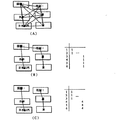
例えば、「ファイル」「新規」「開く」「保存」「終了」の5つラベルを作成し、全てを同時に選択し、メニューに変換した場合、部品データ記憶部4に記憶された部品データは、図12A−図12Eのようになる。
【0062】
次に、本実施形態に係るGUI作成支援装置における変換処理について、図13に従って説明する。
【0063】
図13は、本実施形態に係るGUI作成支援装置における変換処理の流れを説明するための図である。
【0064】
まず、部品データを取得すると、変換部5は、利用可能な部品の一覧を作成する(ステップ1301)。この一覧の作成は、予め定められたフォーマットに従って行われる。このフォーマットは、例えば、『選択されている部品が1つである場合には、「ラベル」、「テキスト」、「ボタン」、「チェックボタン」が選択可能である』、『選択されている部品が複数である場合には、「ラベルの集合」、「テキストフィールドの集合」、「複数行のテキストフィールド」、「コマンドボタンの集合」、「チェックボックスの集合」、「オプションボタンの集合」、「リストボックス」、「コンボボックス」、「ドロップダウンリストボックス」、「タブダイアログ」、「ツリービュー」が選択可能である』、というようなものが定められている。
【0065】
次に、変換部5は、ルール記憶部6に記憶されているルールに基づき、現在の状況にマッチするルールがあるか否かを判断する(ステップ1302)。
【0066】
ここで、ルール記憶部6に記憶されているルールの一例を示す。
【0067】
ルール1:if 文字列=“OK” then 部品名.ボタン+1
これは、選択されている文字列が「OK」ならば、部品候補として「ボタン」の優先順位を上げるというルールである。
【0068】
ルール2:if 文字列=“キャンセル” then 部品名. メニュー−1
これは、選択されている文字列が「キャンセル」ならば、部品候補として「メニュー」の優先順位を下げるというルールである。
【0069】
ルール3:if 文字列1=“ファイル” and 文字列2=“終了” then 部品名1.メニュー+2;部品名*.ボタン+1
これは、2つ以上の部品が選択されていて、文字列に「ファイル」と「終了」が含まれている場合には、「ファイル」はメニューが選択されやすく、それ以外の候補はメニューの部品になるようにボタンの優先順位を上げるためのルールである。
【0070】
ルール4:if 要素数>20 then 部品名.オプションボタン−1これは、選択されている要素数が20以上の場合には、オプションボタンの優先順位を下げるというルールである。
【0071】
なお、以上のルールは、あくまでも一例であり、適宜、ユーザがカスタマイズする等により、追加、変更、削除等することができる。
【0072】
変換部5は、マッチするルールが存在していると判断した場合には、マッチしたルールに従って、ステップ1301で作成した利用可能な部品一覧の優先度の値を変更する(ステップ1303)。ステップ1303の処理の後、ステップ1302に戻り、他にマッチするルールがあるか否かを判断する。マッチするルールがすべてなくなった場合には、変換部5は、頻度情報記憶部7より頻度情報を読み込み、回数を加算することによる頻度情報を用いてステップ1301において作成した利用可能な部品一覧の優先度の値を変更する(ステップ1304)。そして、変換部5は、ステップ1301において作成した利用可能な部品一覧を、該優先度に基づき並べ替える(ステップ1305)。並べ替えられた結果は、部品管理部3の候補選択部27に送出され(ステップ1306)、選択候補が表示されることとなる。
【0073】
使用する表示部品が確定すると、候補選択部27は、学習部8に、該確定した部品データに関する情報を送出する。学習部8は、この情報に基づいて、対応する表示部品の現在の頻度情報に1を加え、これを新たな頻度情報として頻度情報記憶部7の頻度情報を更新する。
【0074】
なお、学習部8において、頻度情報以外にも、事例ベース推論や機能学習、ニューラルネットワーク等を用いることも可能である。確定した表示部品の構成を事例として記憶し、事例ベース推論を用いて、過去に類似する構成があった場合には、過去の事例を修正して候補を作成するようにする。
【0075】
例えば、事例ベース推論を用いることにより、「ファイル」と、「新規」と、「開く」と、「新規保存」と、「保存」と、「終了」というメニューの事例が存在した場合において、「ファイル、新規、開く、保存、終了」というラベル群が作成された場合には、このメニューの事例が類似事例として検索される。検索された事例はメニューであるため、表示部品として「メニュー」が変換候補として選択されやすくなる。
【0076】
次に、第2の実施形態を説明する。
【0077】
GUI部品を変換する場合には、全く新規に部品を作成する場合と、過去に作成したGUI部品を変更する場合とがある。後者の場合、変換するGUI部品は、すでに何らかの意味を持っていることが考えられるので、現在の部品の種別を用いて変換を行う例について説明する。
【0078】
図14は、本実施形態に係るGUI作成支援装置の構成を示す図である。図14において、上述した第1の実施形態と同じ機能実現手段については同じ符号を付している。部品特定部141は、変換されるべき部品の種別を判定するものである。 図15はこの動作を示すフローチャートである。
【0079】
例えば、図16に示すように、「年齢:」と表示されたGUI部品をマウス等により選択して、変換キーによる変換操作を実行すると、変換指示部26は、変換部5に変換指示を送出するとともに、部品特定部141に変換対象のGUI部品を通知し( 図4A及び図4B参照) 、部品特定部141は、このデータをもとにその部品の種別を判定する。本例の場合、以下の2つのGUI部品が抽出され、その種別が判明する。
【0080】
label[” 年齢”:”]()
combo[](” 20歳未満”,” 20〜30歳”,” 30〜40歳”,” 40〜50歳”,” 50〜60歳”,” 60歳以上”)
ここでは、各部品は、
部品種[ 名前](構成要素, …),…
のように記述するものとする。
【0081】
部品種には、現在の部品の種類(部品名)が入る。例えば、label, button, option, combo, frame, menu, …等である。すなわち、上記「label[” 年齢”:”]()」は、「年齢:」という文字列の入ったラベルという意味を表す。ラベルには、構成要素は存在しないので、構成要素は空のカッコである。また、複数の文字列が1つの部品に入っている場合には、構成要素の文字列をカンマで区切って表示する。
【0082】
メニューのような階層構造のGUI部品の場合には、文字列の代わりに部品種とラベル名が入る。例えば、図17に示すように、メニューが階層的に表現されている場合には、
menu[”ファイル”](”開く”,” 閉じる”,[menu](”再読込み”,” 再書出し”))
となる。
【0083】
上記のように、部品特定部141により選択されたGUI部品に関する情報が得られると、部品特定部141は、該得られたGUI部品の情報を変換部5に送出する。変換部5は、ルール記憶部6に記憶されているルールに基づいて、現在のGUI部品を他のGUI部品に変換する。
【0084】
ここで、ルールの記述例を以下に示す。即ち、本発明では、第1の実施形態におけるif−thenルールに代え下記のような標記法を用いることも可能である。
【0085】
部品種( 文字列),部品種( 文字列, …),… −> 部品名( 文字列),部品名( 文字列, …)
すなわち、左辺(矢印「−>」の左側)が成立条件を表し、左辺が成立した場合には右側の部品群に変換する。例えば、
label[””]()−>button[” キャンセル”]()
というルールの場合には、英文字の”cancel”というラベルを変換したら、カタカナの「キャンセル」というボタンに変換することを意味する。また、文字列の代わりに、以下のように、変数名を用いることも可能である。
【0086】
label[$a+”ボタン”](),label[$b]()−>button[$a](),button[$b]()
この場合、「OKボタン」というラベルと、「キャンセル」という名前のラベルが変換された場合に、$aに「OK」が割り当てられ、$bに「キャンセル」が割り当てられ、「OK」、「キャンセル」という2つのボタンに変換される。
【0087】
ここで、ルール記憶部6が、以下のルールを保持しているとする。
【0088】
ルール1[30]:label[$a](),combo[$b*]−>frame[$a](option[$b*]())
ルール2[10]:label[$a]()−>button[$a*]()
ルール3[20]:combo[]($a*)−>kusto[]($a*)
ルール4[15]:label[$a](),combo[$b*]−>menu[$a]($b*)
ルール名の後ろのカッコ内の数字は、各ルールの強さ(重み)である。また、変数名に「*」が含まれるものは、1つ以上の項目を表す。
【0089】
上述のように、部品特定部141によってGUI部品に関する情報が得られたとすると、各ルールの適合度は、以下のようになる。なお、ルールの適合度とは、成立条件の数としている。
【0090】
ルール1=2
ルール2=1
ルール3=1
ルール4=2
さらに、各ルールの強さを掛けて優先度を求めると、
ルール1=60
ルール2=10
ルール3=20
ルール4=30
となり、この結果から、変換候補の順番として、ルール1、ルール4、ルール3およびルール2となる。
【0091】
次に本発明の第3の実施形態を説明する。
【0092】
本実施形態は、GUI部品が配置されるべき画面内またはウィンドウ内の位置に基づいて、適切なGUI部品をより効果的に選択候補とすることを特徴とする。 図18は、本実施形態に係るGUI編集装置の構成を示す図である。
【0093】
図18において、位置算出部181は、GUI部品が現在配置されている画面内の位置を算出するものである。画面内の位置は、例えば、各GUI部品の中心位置をウィンドウ内の上端および左端からの割合の2つの値で表現される。
【0094】
図19はこの装置の動作を示すフローチャートである。
【0095】
GUI部品をマウス等により選択して、変換キーによる変換操作を実行すると( ステップ1901) 、変換指示部26は、変換部5に変換指示を送出するとともに( ステップ1902) 、位置検出部181に変換対象のGUI部品を通知する( ステップ1903) 。位置検出部181は、当該GUI部品の位置を算出する( ステップ1904) 。例えば、図20に示すようなウィンドウであった場合には、それぞれ、ボタン1(12.5%,12.5%) 、ボタン2(37.5%,87.5%) およびボタン3(65.5%,87.5%) という値を変換部5へ出力する( ステップ1905) 。なお、画面上の相対値ではなく画面上の絶対座標を用いることも可能である。変換部5では、この出力に基づきGUI 部品を所定のGUI 部品へ変換する( ステップ1906) 。例えばボタン1の場合には、ボタン1が画面の上部にあるので、上部のメニューに変換される。また、ボタン2の場合には、ボタン2が画面の下部にあるので、下部のメニューに変換される。
【0096】
以下は、ルール記憶部6に保持されているルールの一例である。
【0097】
ルール5[20]:label[$a](>50%,<50%)()−>button[$a]()
label の引数として与えられているパーセント表示の数字は、GUI部品の現在の位置と比較される条件である。つまり、変換候補ラベルの上下の位置が50%よりも大きく(ウィンドウの下半分に位置し)、左右の位置が50%よりも小さい(ウィンドウの左半分に位置している)場合に、このルールの条件を満たすこととなる。
【0098】
本発明によれば、例えば、ウィンドウの上部に配置すべきGUI部品は、例えば、メニューに変換するというように、ユーザにより最適なGUI部品の候補を提示することにより、さらに使いやすいGUIを構築することができるようになる。
【0099】
なお、図18においては、位置検出部181と併せて部品特定部141を設けているが、特に、位置検出部181のみを設けるようにしてもよい。この場合には、ルール1〜4までのルールは不要となる。
【0100】
次に、本発明の第4の実施形態を説明する。
【0101】
図21Aに示すようなウィンドウにおいて、さまざまな「ボタン」が点在するような場合に、どのGUI部品をタイトルとして用いて、どのように配列すればよいかは、ユーザにとって理解しづらく、煩わしい。そこで、本実施形態は、GUI部品のウィンドウ上の配置位置から順序を特定する方法について説明する。
【0102】
図21A に示すようなウィンドウ中に、「年齢:」、「20歳未満」、「20〜30歳」、「30〜40歳」、「40〜50歳」、「50〜60歳」および「60歳以上」の7つのGUI部品(ボタン)が点在しているとする。
【0103】
図22は第4の実施形態に係るGUI作成支援装置の構成を示す図である。
【0104】
図22に示す順序算出部221は、図21A に示した7つのGUI部品を選択し、変換操作を実行した場合、対象としているGUI部品間の順序関係を求めるものである。例えば図21B に示すように、順序決定部221は、選択されたすべてのGUI部品を内接する長方形211の領域について、表示方向縦長の場合には、表示方向上側から順にGUI部品の順序づけを行う。この場合に、あるGUI部品と他のGUI部品との高さの差がN(Nは定数)以内である場合には、表示方向左側に配置されているGUI部品を右側に配置されているGUI部品に優先するように順序づけを行う。
【0105】
選択されたGUI部品を内接する長方形211が表示方向横長の場合には、表示方向左側から順にGUI部品の順序づけを行う。この場合に、横の差がM以内である場合には、表示方向上側に配置されたGUI部品を下側に配置されているGUI部品に優先して順序づけを行う。なお、M,Nは整列しようとする部品の大きさの逆数でもよい。
【0106】
図21Bに示した例では、内接長方形211は、縦長であると判断されるため、上側優先でGUI部品の順序づけを行う。
【0107】
図23は、順序決定部221の動作を説明するための図である。
【0108】
同図において、選択されたすべてのGUI部品を内接する長方形の領域が、縦長または正方形であるか否かの判定を行う(STEP2301)。縦長であると判定された場合には、表示方向上側優先で順序づけを行うため、縦方向優先フラグをセットする(STEP2302)。一方、横長であると判定された場合には、横方向優先フラグをセットする(SてP2303)。このフラグに示される方向からGUI部品が選択されることとなる。次に、順序決定部221は、ループ処理のための初期化を行い(STEP2304)、変数jが選択されたGUI部品数を越えるまで以下に示す処理を繰り返す(STEP2305)。
【0109】
まず、順序決定部221は、方向優先フラグに従って、i番目とj番目のGUI部品を選択し(STEP2306)、この2つのGUI部品の位置の差が定数N以内であるか否かを判定する(STEP2307)。ここで、位置の差とは、縦方向優先の場合には2GUI部品の水平中心軸間の差(つまり、高さ)であり、横方向優先の場合には垂直中心軸間の差である。STEP2307において、N以内であると判断された場合には、i番目のGUI部品がj番目のGUI部品よりも左(横方向優先の場合には上)に位置しているか否かを判断する(STEP2308)。左(上)側に位置していると判断された場合には、i番目のGUI部品の順位をpとし、j番目のGUI部品の順位をそれより1つ下げる(STEP2309)。なお、STEP2307において、Nより大きいと判断された場合には、このSTEP2309の処理を行う。
【0110】
一方、STEP2308において、左(上)側に位置していないと判断された場合には、i番目とj番目のGUI部品の優先順位を入れ替える。その後、順序決定部221は、着目するGUI部品を1つシフトするため、変数を1つ分インクリメントし(STEP2311)、以上の処理について条件を満足するまで繰り返す。
【0111】
以上の処理により、以下のように各GUI部品の順序が決定される。
【0112】
1 「年齢:」
2 「20歳未満」
3 「20〜30歳」
4 「30〜40歳」
5 「40〜50歳」
6 「50〜60歳」
7 「60歳以上」
ここで、ルール記憶部6に
button[$a](),button[$b*]()−>label[$a](),combo[$b*]()
というルールが記憶されている場合、このルールにマッチすることにより、上述した図16に示すような画面に変換されることとなる。
【0113】
なお、順序付けは、上記に示した方法に限るものではなく、一意に順序づけられることができればよい。例えば、部品が選択された順番、左優先、上優先、最初からL個のGUI部品より上優先、左優先を判定等がある。
【0114】
次に、本発明の第5の実施形態を説明する。
【0115】
本実施形態は、複数のGUI部品をグループ化して、このグループ化されたGUI部品について変換操作を行うことにより、より最適なGUI部品の配置を行うことができるようにするものである。
【0116】
例えば、図24Aに示すようなウィンドウにGUI部品が配置されている場合に、通常の変換を行うと図24Bのようになる。これに対し、本実施形態では、図24Cに示すような変換を行うことができるようにする。
【0117】
図25は、本実施形態に係るGUI部品作成支援装置の構成を示す図である。同図において、部品グループ化部251は、入力部1からのグループ化の指示に従い、所定のルールに基づいて特定のGUI部品群をグループ化するものであり、部品グループ化解除部252は、入力部1からのグループ化解除の指示に従い、部品グループ化部251によってグループ化されたGUI部品群のグループ化を解除するものである。
【0118】
図26は、部品グループ化部におけるグループ化の手順を示す図である。
【0119】
まず、配置されたすべてのGUI部品のそれぞれについて、2つのGUI部品ごとに関係付け(STEP2601)、そのGUI部品間の直線距離を求める
(STEP2602)。GUI部品間距離は、例えば、各GUI部品の中心間の直線距離とする。
【0120】
図27Aは、GUI部品間距離の算出のための概念図である。すなわち、図27Aは、図24Aに示されたウィンドウ内のGUI部品について、その中心間を直線で結んだ状態を示している。
【0121】
次に、関係づけられた線分のうち、最も長い線分のものを1つ選択し(STEP2603)、そのGUI部品間の関係を解除する(STEP2604)。解除した後、各GUI部品(要素)について、所定の順番に線分をたどっていく(STEP2605)。これによって、各GUI部品がすべて線分で連結されているか、つまり、分割されたか否かを調べる(STEP2606)。より具体的には、GUI部品“1”(この場合、GUI部品「国籍」を“1”としている。)を起点として、GUI部品“2”方向にたどっていき、たどることができる場合は、内部テーブル(例えば、配列変数)に“1”をマークしていく。これをすべてのGUI部品について調べることによって、各GUI部品が分割されているか否かを調べることができる((図27B)。
【0122】
STEP2606において、分割されていないと判断された場合には、STEP2603に戻り、上記処理を繰り返す。
【0123】
関係の解除が進み、例えば、図27Cの状態になったとする。この場合、「国籍」、「日本」および「日本以外」のグループと、「性別」、「男」および「女」のグループとに分割されているので、グループ化は終了する。
【0124】
なお、GUI部品間距離の算出方法は、上記方法に限りものではなく、例えば、GUI部品端部の距離等でもかまわない。また、グループ化の方法も上記に示した方法に限りものではない。例えば、マウス等でグループ化したいGUI部品を選択した後、グループ化指示の命令を入力するようにしてもよい。
【0125】
次に、本発明の第6の実施形態を説明する。
【0126】
上述した第5の実施形態では、同一距離で2つ以上のグループが存在した場合には、分割する個数が判定できない場合がある。そこで、本実施形態では、グループ数算出部によりグループ数を検出する。
【0127】
図28は、本実施形態に係るGUI編集装置の構成を示す図である。
【0128】
入力部1からグループ分割の指示が入力されると、部品特定部141は、選択されているGUI部品の種類を特定し、グループ数算出部281に送出する。グループ数算出部281は、グループごとにその数を数え、数の少ないものから順にグループ数の候補とし、これをグループ化部251に送出する。グループ化部281は、指示されたグループ数になるまで分割を行う。再度、グループ化の要求があった場合には、次のグループ数の候補になるまで分割を行う。
【0129】
【発明の効果】
以上説明した通り、本発明のGUI作成支援装置によれば、同等の意味を持つGUI部品の交換が容易になり、より使い勝手の良いGUIを効率良く作成することができる。
【0130】
また、本発明によれば、GUI部品の種別やその画面上での配置位置、配置順序等を考慮するので、操作性および変換効率の優れたGUI作成支援装置を提供することが可能となる。
【図面の簡単な説明】
【図1】本発明の第1の実施形態に係るGUI作成支援装置の構成を示す図である。
【図2】図1に示した部品管理部の構成を示す図である。
【図3】ウィンドウの初期状態の一例を示す図である。
【図4】図1に示した部品記憶部に記憶された部品データの一例を示す図である。
【図5】文字列を入力し終わった状態のウィンドウの一例を示す図である。
【図6】ドラッグ&ドロップ操作の状態のウィンドウの一例を示す図である。
【図7】第1の実施形態に係るGUI作成支援装置の動作を示すフローチャートである。
【図8】図6のラベル群がコンボボックスに変換された状態のウィンドウの一例を示す図である。
【図9】次候補変換指示により標準コンボに変換された状態のウィンドウの一例を示す図である。
【図10】次候補変換指示によりメニューに変換された状態のウィンドウの一例を示す図である。
【図11】表示部品の並び順の入れ替え操作の状態のウィンドウの一例を示す図である。
【図12】図1に示した部品記憶部に記憶された部品データの一例を示す図である。
【図13】第1の実施形態に係るGUI作成支援装置における変換処理の流れを示すフローチャートである。
【図14】第2の実施形態に係るGUI作成支援装置の構成を示す図である。
【図15】第2の実施形態に係るGUI作成支援装置の動作を示すフローチャートである。
【図16】第2の実施形態における表示画面の一例を示す図である。
【図17】第2の実施形態における表示画面の一例を示す図である。
【図18】第3の実施形態に係るGUI作成支援装置の構成を示す図である。
【図19】第3の実施形態に係るGUI作成支援装置の動作を示すフローチャートである。
【図20】第3の実施形態を説明するための表示画面の一例を示す図である。
【図21】第4の実施形態を説明するための表示画面の一例を示す図である。
【図22】第4の実施形態に係るGUI作成支援装置の構成を示す図である。
【図23】図22に示した順序決定部の動作を説明するための図である。
【図24】第5の実施形態を説明するための表示画面の一例を示す図である。
【図25】第5の実施形態に係るGUI作成支援装置の構成を示す図である。
【図26】図25に示した部品グループ化部におけるグループ化の手順を示す図である。
【図27】図25に示した部品グループ化部におけるグループ化の一例を示す図である。
【図28】第6の実施形態に係るGUI作成支援装置の構成を示す図である。
【符号の説明】
1 入力部
2 表示部
3 部品管理部
4 部品記憶部
5 変換部
6 ルール記憶部
7 頻度記憶部
8 学習部
21 入力情報解釈部
22 部品データ登録部
23 部品選択部
24 画面データ記憶部
25 部品データ読み出し部
26 変換指示部
27 候補選択部[0001]
TECHNICAL FIELD OF THE INVENTION
The present invention relates to a GUI creation support device that supports creation of a graphical user interface (hereinafter, referred to as “GUI”) such as a computer application program, a GUI creation support method, and a recording medium on which a GUI creation support program is recorded.
[0002]
[Prior art]
In many cases, a GUI creation support device (GUI builder) is used for designing and creating a GUI.
[0003]
A general GUI creation support device designs and creates a GUI by selecting and arranging buttons and lists called GUI components from a palette in a window frame whose size can be freely changed. This work is performed by a GUI designer, and the data exchanged between the computer user and the computer is expressed as a specific GUI display screen using the GUI display screen. In designing and creating a GUI using such a GUI creation support device, there are the following problems.
[0004]
That is, designing and creating a GUI using the GUI creation support device has an advantage that the GUI screen can be easily designed by a method of drawing a picture. However, this advantage, on the contrary, causes a problem that the GUI is designed and created without imagining the final completed state, and a reworking process occurs later. In other words, parts are added or functions are changed in the design process. In particular, in the case of data to be selected and input from candidates, candidates may be added in the future. Some GUI parts are provided only for selection from fixed candidates, and others take into account the addition of candidates. Considering that a candidate is fixed, use parts for selection from fixed candidates. If there is a candidate, the GUI screen must be recreated when the candidate is added. Therefore, the designer has to design and create while imagining the final completed state while considering specifically which parts are used and how.
[0005]
For example, when creating a GUI that selects one item from a plurality of items, an expression method (parts) such as a pull-down menu, an exclusive button, and a list box is prepared. In such a case, which method should be followed depends on the operation scene and the like, and further depends on the preference of the user or the designer. In such a case, the conventional GUI creation support apparatus has few means for changing from a certain expression method to another expression method, and once it is decided to express it with a certain part, it is replaced with another part. Therefore, the same operation as that of reconstructing the corresponding GUI screen is required.
[0006]
Before creating an actual system, a mock-up for confirming the appearance and behavior of the system is generally performed. However, creating the mockup itself was very cumbersome and inconvenient.
[0007]
[Problems to be solved by the invention]
SUMMARY OF THE INVENTION The present invention has been made to solve the above-mentioned problems, and has been made in consideration of a GUI creation support apparatus, a GUI creation support method, and a GUI creation support method capable of designing and creating a GUI interactive screen excellent in operability and maintainability. It is an object to provide a recording medium on which a program is recorded.
[0008]
A further object of the present invention is to provide a GUI creation support apparatus, a GUI creation support method, and a recording medium on which a program for GUI creation support is recorded in consideration of information as to which GUI component to be converted is currently. And
[0009]
Another object of the present invention is to provide a GUI creation support device, a GUI creation support method, and a recording medium that records a GUI creation support program in consideration of the current arrangement state of GUI components to be converted.
[0010]
[Means for Solving the Problems]
In order to solve this problem, the present invention according to
[0011]
The present invention according to
[0027]
According to the present invention, for example, when one GUI object (display component) is selected from the GUI under design and the conversion key is pressed, the current display component is converted to another display component. For example, if a “label” written as “OK” is selected and converted, it is converted into a “text field” written as “OK”. Then press the convert key again
It is converted to a "button" written "OK". When the conversion key is further pressed, it is converted into an option button written "OK". When one object is selected, for example, objects of “label”, “text field”, “button”, and “check box” are conversion candidates.
[0028]
Similarly, conversion is performed when a plurality of GUI objects are selected and then converted. The conversion candidates are, for example, “set of labels”, “set of text fields”, “multi-line text field”, “set of command buttons”, “set of check boxes”, “set of option buttons”, “list of options”. Box, combo box, drop-down list box, tab dialog, and tree view objects are conversion candidates. Note that these names are merely examples of conversion candidates. The present invention is not limited to this. The order of such selection candidates can be changed or learned based on the frequency of use of each component or the label name.
[0029]
BEST MODE FOR CARRYING OUT THE INVENTION
Hereinafter, embodiments of the present invention will be described with reference to the drawings.
[0030]
FIG. 1 is a diagram showing a configuration of a GUI creation support device according to an embodiment of the present invention. In FIG. 1, an
[0031]
The
[0032]
Next, the
[0033]
FIG. 2 is a diagram illustrating a configuration of the
[0034]
First, when the input
[0035]
When the input
[0036]
Further, when interpreting that the input information is a component conversion instruction, the input
[0037]
The selection of the selection candidate is performed, for example, by sequentially selecting from the top of the candidate list, and after selecting all of the candidate lists, the top candidate is selected again. Such selection of the next candidate is performed by the input
[0038]
If the input
[0039]
Next, the operation of the GUI creation support device according to the present invention will be described using an example. When the GUI creation support device is started up, a window (Form) in which no components or the like are arranged is displayed on the
[0040]
Now, assume that five character strings are input using the
[0041]
FIGS. 4A and 4B are diagrams illustrating an example of component data stored in the
[0042]
Here, each item will be described.
[0043]
The
[0044]
The number of
[0045]
The
[0046]
The number of
[0047]
The
[0048]
The
[0049]
The
[0050]
The
[0051]
The
[0052]
The
[0053]
The
[0054]
FIG. 5 shows a window in which all the five character strings have been input. The above-described component data is stored for each label shown in FIG.
[0055]
Next, using the
[0056]
FIG. 7 is a flowchart showing the operation of the
[0057]
In the
[0058]
FIG. 8 is a diagram illustrating an example of a state where the label group of FIG. 6 is converted into a combo box. The user gives a next candidate conversion instruction through the
[0059]
FIG. 9 is a diagram illustrating an example of a state where the standard combo is converted according to the next candidate conversion instruction. When the user gives the next candidate conversion instruction again, a menu is displayed as the next candidate. FIG. 10 is a diagram illustrating an example of a state where the menu is converted by the next candidate conversion instruction. Thus, the user repeats the next candidate conversion instruction using the
[0060]
If the arrangement of the display components is not the desired arrangement, it is also possible to select an item in the menu and directly move the display component to the destination. That is, the user selects an item of the corresponding display component by the
[0061]
For example, if five labels of “file”, “new”, “open”, “save”, and “end” are created, all of them are selected at the same time, and converted into a menu, the component data stored in the component
[0062]
Next, conversion processing in the GUI creation support device according to the present embodiment will be described with reference to FIG.
[0063]
FIG. 13 is a diagram for explaining the flow of the conversion process in the GUI creation support device according to the present embodiment.
[0064]
First, when component data is acquired, the
[0065]
Next, the
[0066]
Here, an example of a rule stored in the
[0067]
Rule 1: if Character string = “OK” then Part name.
This is a rule that if the selected character string is “OK”, the priority of “button” is raised as a component candidate.
[0068]
Rule 2: if Character string = “cancel” then Part name. Menu-1
This is a rule that if the selected character string is “cancel”, the priority of “menu” is reduced as a component candidate.
[0069]
Rule 3: if
This means that if two or more parts are selected and the character string contains “File” and “End”, “File” is easier to select a menu, and other candidates are This is a rule for raising the priority of buttons so that they become parts.
[0070]
Rule 4: if element count> 20 then part name. Option Button-1 This is a rule that lowers the priority of the option button when the number of selected elements is 20 or more.
[0071]
Note that the above rules are merely examples, and can be added, changed, deleted, and the like by customizing the user as appropriate.
[0072]
When determining that a matching rule exists, the
[0073]
When the display component to be used is determined, the
[0074]
In the
[0075]
For example, by using the case-based reasoning, if there is a case of a menu of “File”, “New”, “Open”, “Save as new”, “Save”, and “Exit”, “ When a label group “File, New, Open, Save, Exit” is created, the case in this menu is searched as a similar case. Since the searched case is a menu, "menu" is easily selected as a conversion candidate as a display component.
[0076]
Next, a second embodiment will be described.
[0077]
When converting a GUI component, there are a case where a completely new component is created and a case where a previously created GUI component is changed. In the latter case, since the GUI component to be converted may already have some meaning, an example in which conversion is performed using the current component type will be described.
[0078]
FIG. 14 is a diagram illustrating a configuration of a GUI creation support device according to the present embodiment. In FIG. 14, the same reference numerals are given to the same function realizing means as in the first embodiment described above. The
[0079]
For example, as shown in FIG. 16, when a GUI component displaying “age:” is selected with a mouse or the like and a conversion operation is performed using a conversion key, the
[0080]
label ["age": "] ()
combo [] ("under 20 years old", "20-30 years old", "30-40 years old", "40-50 years old", "50-60 years old", "60 years old or older")
Here, each part is
Part type [name] (component,…),…
It should be described as follows.
[0081]
The type (part name) of the current part is entered in the part type. For example, label, button, option, combo, frame, menu,... That is, "label [" age ":"] () "means a label including a character string" age: ". The components are empty parentheses because the label has no components. When a plurality of character strings are included in one part, the character strings of the constituent elements are displayed separated by commas.
[0082]
In the case of a GUI component having a hierarchical structure such as a menu, a component type and a label name are entered instead of a character string. For example, as shown in FIG. 17, when the menu is hierarchically expressed,
menu ["file"] ("open", "close", [menu] ("reread", "rewrite"))
It becomes.
[0083]
As described above, when the information on the GUI component selected by the
[0084]
Here, a description example of the rule is shown below. That is, in the present invention, the following notation method can be used instead of the if-then rule in the first embodiment.
[0085]
Part type (character string), part type (character string, ...), ...-> part name (character string), part name (character string, ...)
In other words, the left side (the left side of the arrow "->") represents a condition to be satisfied, and when the left side is satisfied, the condition is converted into a right component group. For example,
label [""] ()-> button ["cancel"] ()
In the case of the rule, it means that if the label "cancel" of the English character is converted, it is converted into a button of "cancel" in katakana. Instead of a character string, a variable name can be used as follows.
[0086]
label [¥ a + "button"] (), label [¥ b] ()-> button [¥ a] (), button [¥ b] ()
In this case, when the label "OK button" and the label "Cancel" are converted, "OK" is assigned to $ a, "Cancel" is assigned to $ b, and "OK", "OK" is assigned. It is converted into two buttons "Cancel".
[0087]
Here, it is assumed that the
[0088]
Rule 1 [30]: label [$ a] (), combo [$ b *]-> frame [$ a] (option [$ b *] ())
Rule 2 [10]: label [$ a] ()-> button [$ a *] ()
Rule 3 [20]: combo [] ($ a *)-> custo [] ($ a *)
Rule 4 [15]: label [$ a] (), combo [$ b *]-> menu [$ a] ($ b *)
The number in parentheses after the rule name is the strength (weight) of each rule. In addition, a variable name including “*” indicates one or more items.
[0089]
As described above, assuming that information on the GUI component is obtained by the
[0090]
Furthermore, if you calculate the priority by multiplying the strength of each rule,
From this result, the order of the conversion candidates is
[0091]
Next, a third embodiment of the present invention will be described.
[0092]
The present embodiment is characterized in that an appropriate GUI component is more effectively selected as a selection candidate based on a position in a screen or a window where the GUI component is to be arranged. FIG. 18 is a diagram illustrating a configuration of a GUI editing device according to the present embodiment.
[0093]
In FIG. 18, a
[0094]
FIG. 19 is a flowchart showing the operation of this device.
[0095]
When a GUI component is selected with a mouse or the like and a conversion operation is performed using a conversion key (step 1901), the
[0096]
The following is an example of a rule stored in the
[0097]
Rule 5 [20]: label [$ a] (> 50%, <50%) ()-> button [$ a] ()
The percentage number given as the label argument is a condition to be compared with the current position of the GUI part. That is, if the vertical position of the conversion candidate label is larger than 50% (located in the lower half of the window) and the horizontal position is smaller than 50% (located in the left half of the window), this rule is used. Will be satisfied.
[0098]
According to the present invention, for example, a GUI component to be arranged at the top of a window is converted into a menu, and the user is presented with an optimal GUI component candidate, thereby constructing a GUI that is easier to use. Will be able to do it.
[0099]
In FIG. 18, the
[0100]
Next, a fourth embodiment of the present invention will be described.
[0101]
In the case where various “buttons” are scattered in the window as shown in FIG. 21A, it is difficult for the user to understand which GUI component should be used as the title and how to arrange the GUI components. Therefore, in the present embodiment, a method for specifying the order from the arrangement position of the GUI parts on the window will be described.
[0102]
In a window as shown in FIG. 21A, “age:”, “under 20”, “20-30”, “30-40”, “40-50”, “50-60” and “50” It is assumed that seven GUI parts (buttons) of “over 60 years old” are scattered.
[0103]
FIG. 22 is a diagram illustrating a configuration of a GUI creation support device according to the fourth embodiment.
[0104]
The
[0105]
If the
[0106]
In the example shown in FIG. 21B, since the inscribed
[0107]
FIG. 23 is a diagram for explaining the operation of the
[0108]
In the figure, it is determined whether or not the rectangular area inscribed in all the selected GUI parts is vertically long or square (STEP 2301). If it is determined that the image is vertically long, a vertical direction priority flag is set (STEP 2302) in order to perform the ordering in the display direction upper side priority. On the other hand, when it is determined that the image is horizontally long, the horizontal direction priority flag is set (S2303). The GUI component is selected from the direction indicated by this flag. Next, the
[0109]
First, the
[0110]
On the other hand, if it is determined in
[0111]
By the above processing, the order of each GUI component is determined as follows.
[0112]
1. "Age:"
2 "Under 20"
3 "20-30 years old"
4 "30-40 years old"
5 "40-50 years old"
6 "50-60 years old"
7 "Over 60 years old"
Here, the
button [$ a] (), button [$ b *] ()-> label [$ a] (), combo [$ b *] ()
Is stored, the screen is converted to a screen as shown in FIG. 16 described above by matching this rule.
[0113]
Note that the ordering is not limited to the method described above, and it is sufficient that the ordering can be performed uniquely. For example, the order in which the components are selected, left priority, upper priority, determination of upper priority, left priority over L GUI components from the beginning, and the like are available.
[0114]
Next, a fifth embodiment of the present invention will be described.
[0115]
In the present embodiment, a plurality of GUI parts are grouped, and a conversion operation is performed on the grouped GUI parts, so that more optimal arrangement of the GUI parts can be performed.
[0116]
For example, when GUI components are arranged in a window as shown in FIG. 24A, normal conversion is performed as shown in FIG. 24B. On the other hand, in the present embodiment, the conversion as shown in FIG. 24C can be performed.
[0117]
FIG. 25 is a diagram illustrating a configuration of a GUI component creation support device according to the present embodiment. In the figure, a
[0118]
FIG. 26 is a diagram illustrating a grouping procedure in the component grouping unit.
[0119]
First, for each of the arranged GUI components, a relationship is established for each of the two GUI components (STEP 2601), and a linear distance between the GUI components is determined.
(STEP 2602). The GUI component distance is, for example, a linear distance between the centers of the GUI components.
[0120]
FIG. 27A is a conceptual diagram for calculating the distance between GUI components. That is, FIG. 27A shows a state where the centers of the GUI parts in the window shown in FIG. 24A are connected by a straight line.
[0121]
Next, one of the longest line segments is selected from the associated line segments (STEP 2603), and the relationship between the GUI components is released (STEP 2604). After the release, the line segments are traced in a predetermined order for each GUI component (element) (STEP 2605). As a result, it is checked whether all the GUI components are connected by line segments, that is, whether or not the GUI components are divided (STEP 2606). More specifically, starting from the GUI part “1” (in this case, the GUI part “Nationality” is set to “1”), if the user can trace in the direction of the GUI part “2”, “1” is marked on the internal table (for example, an array variable). By checking this for all the GUI components, it can be checked whether or not each GUI component is divided (FIG. 27B).
[0122]
If it is determined in
[0123]
It is assumed that the cancellation of the relationship progresses and, for example, the state of FIG. In this case, the groups are divided into groups of "nationality", "Japan" and "other than Japan" and groups of "sex", "male" and "female", and the grouping ends.
[0124]
The method of calculating the distance between the GUI components is not limited to the above method, and may be, for example, the distance between the ends of the GUI components. Also, the grouping method is not limited to the method described above. For example, after selecting a GUI component to be grouped with a mouse or the like, a command for grouping instruction may be input.
[0125]
Next, a sixth embodiment of the present invention will be described.
[0126]
In the fifth embodiment described above, when two or more groups exist at the same distance, the number of divisions may not be determined. Therefore, in the present embodiment, the number of groups is detected by the group number calculation unit.
[0127]
FIG. 28 is a diagram showing the configuration of the GUI editing device according to the present embodiment.
[0128]
When an instruction to divide a group is input from the
[0129]
【The invention's effect】
As described above, according to the GUI creation support device of the present invention, replacement of GUI parts having the same meaning is facilitated, and a more convenient GUI can be created efficiently.
[0130]
Further, according to the present invention, since the type of the GUI component, the arrangement position on the screen, the arrangement order, and the like are taken into account, it is possible to provide a GUI creation support device having excellent operability and conversion efficiency.
[Brief description of the drawings]
FIG. 1 is a diagram illustrating a configuration of a GUI creation support device according to a first embodiment of the present invention.
FIG. 2 is a diagram illustrating a configuration of a component management unit illustrated in FIG. 1;
FIG. 3 is a diagram illustrating an example of an initial state of a window.
FIG. 4 is a diagram illustrating an example of component data stored in a component storage unit illustrated in FIG. 1;
FIG. 5 is a diagram illustrating an example of a window in a state where a character string has been input.
FIG. 6 is a diagram illustrating an example of a window in a state of a drag and drop operation.
FIG. 7 is a flowchart illustrating an operation of the GUI creation support device according to the first embodiment.
8 is a diagram illustrating an example of a window in a state where the label group in FIG. 6 is converted into a combo box.
FIG. 9 is a diagram illustrating an example of a window that has been converted to a standard combo according to a next candidate conversion instruction.
FIG. 10 is a diagram illustrating an example of a window in a state where the window is converted into a menu according to a next candidate conversion instruction.
FIG. 11 is a diagram illustrating an example of a window in a state of an operation of changing the arrangement order of display components.
FIG. 12 is a diagram illustrating an example of component data stored in a component storage unit illustrated in FIG. 1;
FIG. 13 is a flowchart illustrating a flow of a conversion process in the GUI creation support device according to the first embodiment.
FIG. 14 is a diagram illustrating a configuration of a GUI creation support device according to a second embodiment.
FIG. 15 is a flowchart illustrating an operation of the GUI creation support device according to the second embodiment.
FIG. 16 is a diagram illustrating an example of a display screen according to the second embodiment.
FIG. 17 is a diagram illustrating an example of a display screen according to the second embodiment.
FIG. 18 is a diagram illustrating a configuration of a GUI creation support device according to a third embodiment.
FIG. 19 is a flowchart illustrating an operation of the GUI creation support device according to the third embodiment.
FIG. 20 is a diagram showing an example of a display screen for explaining the third embodiment.
FIG. 21 is a diagram showing an example of a display screen for explaining a fourth embodiment.
FIG. 22 is a diagram illustrating a configuration of a GUI creation support device according to a fourth embodiment.
FIG. 23 is a diagram for explaining the operation of the order determining unit shown in FIG. 22;
FIG. 24 is a diagram showing an example of a display screen for explaining a fifth embodiment.
FIG. 25 is a diagram illustrating a configuration of a GUI creation support device according to a fifth embodiment.
26 is a diagram illustrating a grouping procedure in the component grouping unit illustrated in FIG. 25;
FIG. 27 is a diagram illustrating an example of grouping in the component grouping unit illustrated in FIG. 25;
FIG. 28 is a diagram illustrating a configuration of a GUI creation support device according to a sixth embodiment.
[Explanation of symbols]
1 Input section
2 Display
3 Parts management department
4 Parts storage unit
5 Conversion unit
6 Rule storage
7 Frequency storage
8 Learning Department
21 Input information interpreter
22 Parts data registration section
23 Parts selection section
24 Screen data storage
25 Component data reading section
26 Conversion instruction section
27 Candidate selection section
Claims (2)
ユーザからの選択指示および入力指示に基づいて、前記記憶手段から前記表示部品データを選択するとともに該選択された表示部品データの表示情報として前記入力指示の内容を設定する設定入力手段と、
ユーザからの変換指示に基づいて、前記選択された表示部品データの機能情報に代えて変換されるべき機能情報候補を、前記記憶手段に格納された表示部品データの機能情報の中から選択する変換候補選択手段と、
前記設定された表示情報に基づいて、前記選択された変換されるべき機能情報候補に優先順位情報を付加する優先情報付加手段と、
前記優先情報に基づいて前記機能情報候補を前記表示画面に表示する候補表示手段と
を具備することを特徴とするGUI作成支援装置。 Storage means for storing display component data including function information indicating the content of the function and display information indicating the display content on the display screen,
Setting input means for selecting the display component data from the storage means based on a selection instruction and an input instruction from a user and setting the content of the input instruction as display information of the selected display component data;
A conversion for selecting a function information candidate to be converted instead of the function information of the selected display component data from the function information of the display component data stored in the storage unit based on a conversion instruction from a user. Candidate selection means;
Priority information adding means for adding priority information to the selected function information candidates to be converted, based on the set display information,
A GUI creation support device, comprising: candidate display means for displaying the function information candidates on the display screen based on the priority information .
ユーザからの選択指示に基づいて、前記記憶手段から前記表示部品データを選択する選択入力手段と、
前記選択された表示部品データの機能情報に基づいて、前記選択された表示部品データに代えて変換されるべき表示部品データ候補を前記記憶手段から選択して、前記表示画面に表示する変換候補表示手段と
を具備することを特徴とするGUI作成支援装置。 Storage means for storing display component data including function information indicating the content of the function,
Selection input means for selecting the display component data from the storage means based on a selection instruction from a user,
A conversion candidate display for selecting display component data candidates to be converted in place of the selected display component data from the storage unit based on the function information of the selected display component data and displaying the candidate on the display screen GUI creation support apparatus characterized by comprising a <br/> and means.
Priority Applications (1)
| Application Number | Priority Date | Filing Date | Title |
|---|---|---|---|
| JP26436297A JP3588540B2 (en) | 1996-09-30 | 1997-09-29 | GUI creation support device, GUI creation support method, and recording medium recording GUI creation support program |
Applications Claiming Priority (5)
| Application Number | Priority Date | Filing Date | Title |
|---|---|---|---|
| JP25953596 | 1996-09-30 | ||
| JP8-259535 | 1997-08-08 | ||
| JP21456097 | 1997-08-08 | ||
| JP9-214560 | 1997-08-08 | ||
| JP26436297A JP3588540B2 (en) | 1996-09-30 | 1997-09-29 | GUI creation support device, GUI creation support method, and recording medium recording GUI creation support program |
Publications (2)
| Publication Number | Publication Date |
|---|---|
| JPH11110205A JPH11110205A (en) | 1999-04-23 |
| JP3588540B2 true JP3588540B2 (en) | 2004-11-10 |
Family
ID=27329635
Family Applications (1)
| Application Number | Title | Priority Date | Filing Date |
|---|---|---|---|
| JP26436297A Expired - Fee Related JP3588540B2 (en) | 1996-09-30 | 1997-09-29 | GUI creation support device, GUI creation support method, and recording medium recording GUI creation support program |
Country Status (1)
| Country | Link |
|---|---|
| JP (1) | JP3588540B2 (en) |
Families Citing this family (2)
| Publication number | Priority date | Publication date | Assignee | Title |
|---|---|---|---|---|
| JP4794927B2 (en) * | 2005-07-12 | 2011-10-19 | キヤノン株式会社 | Information processing apparatus, information processing method, and program |
| JPWO2022239165A1 (en) * | 2021-05-12 | 2022-11-17 |
-
1997
- 1997-09-29 JP JP26436297A patent/JP3588540B2/en not_active Expired - Fee Related
Also Published As
| Publication number | Publication date |
|---|---|
| JPH11110205A (en) | 1999-04-23 |
Similar Documents
| Publication | Publication Date | Title |
|---|---|---|
| US5973686A (en) | GUI edition aiding apparatus, GUI edition aiding method, and record medium recording GUI edition aiding program | |
| JP4970714B2 (en) | Extract metadata from a specified document area | |
| JP4356847B2 (en) | Field definition information generation method, line and field definition information generation device | |
| US7334195B2 (en) | System and process for presenting search results in a histogram/cluster format | |
| US5668966A (en) | System and method for direct manipulation of search predicates using a graphical user interface | |
| US5894311A (en) | Computer-based visual data evaluation | |
| US5675753A (en) | Method and system for presenting an electronic user-interface specification | |
| US7458034B2 (en) | Data organization support method and program product therefor | |
| US6760039B2 (en) | Program for graphic priority editing | |
| JP2015046178A (en) | System, method and computer program for creating and manipulating data structures using interactive graphical interface | |
| WO1999033009A1 (en) | Publication file conversion and display | |
| JP2002351917A (en) | Customer self-service subsystem for detection and verification of context cluster | |
| KR20070006760A (en) | Method for creating an icon, representing a group of images, computer system, computer program product and a data carrier arranged for performing the method | |
| JP2007265031A (en) | Dictionary content processor, content display system and content display method | |
| US6288732B1 (en) | Information processor | |
| US20100185967A1 (en) | Information Processing Device, and File Managing Method | |
| JP3448874B2 (en) | Document processing apparatus and document processing method | |
| JP3588540B2 (en) | GUI creation support device, GUI creation support method, and recording medium recording GUI creation support program | |
| JP2585311B2 (en) | How to create a program | |
| JP3198941B2 (en) | Information processing device and recording medium | |
| JP4189461B2 (en) | File management program, computer-readable recording medium storing file management program, file management apparatus, and file management method | |
| Munro et al. | Forming Relationships | |
| JPH0421229B2 (en) | ||
| JP2024001395A (en) | Logic creation aiding system | |
| JPH1031752A (en) | Device for modifying recognition result of drawing input device |
Legal Events
| Date | Code | Title | Description |
|---|---|---|---|
| A131 | Notification of reasons for refusal |
Free format text: JAPANESE INTERMEDIATE CODE: A131 Effective date: 20040406 |
|
| A521 | Written amendment |
Free format text: JAPANESE INTERMEDIATE CODE: A523 Effective date: 20040607 |
|
| TRDD | Decision of grant or rejection written | ||
| A01 | Written decision to grant a patent or to grant a registration (utility model) |
Free format text: JAPANESE INTERMEDIATE CODE: A01 Effective date: 20040810 |
|
| A61 | First payment of annual fees (during grant procedure) |
Free format text: JAPANESE INTERMEDIATE CODE: A61 Effective date: 20040816 |
|
| LAPS | Cancellation because of no payment of annual fees |