JP3587635B2 - Personal recognition device using iris and automatic transaction system using this personal recognition device - Google Patents
Personal recognition device using iris and automatic transaction system using this personal recognition device Download PDFInfo
- Publication number
- JP3587635B2 JP3587635B2 JP30446896A JP30446896A JP3587635B2 JP 3587635 B2 JP3587635 B2 JP 3587635B2 JP 30446896 A JP30446896 A JP 30446896A JP 30446896 A JP30446896 A JP 30446896A JP 3587635 B2 JP3587635 B2 JP 3587635B2
- Authority
- JP
- Japan
- Prior art keywords
- subject
- position information
- eye
- image
- camera
- Prior art date
- Legal status (The legal status is an assumption and is not a legal conclusion. Google has not performed a legal analysis and makes no representation as to the accuracy of the status listed.)
- Expired - Fee Related
Links
Images


Classifications
-
- G—PHYSICS
- G06—COMPUTING OR CALCULATING; COUNTING
- G06V—IMAGE OR VIDEO RECOGNITION OR UNDERSTANDING
- G06V40/00—Recognition of biometric, human-related or animal-related patterns in image or video data
- G06V40/10—Human or animal bodies, e.g. vehicle occupants or pedestrians; Body parts, e.g. hands
- G06V40/18—Eye characteristics, e.g. of the iris
Landscapes
- Engineering & Computer Science (AREA)
- Health & Medical Sciences (AREA)
- General Health & Medical Sciences (AREA)
- Ophthalmology & Optometry (AREA)
- Human Computer Interaction (AREA)
- Physics & Mathematics (AREA)
- General Physics & Mathematics (AREA)
- Multimedia (AREA)
- Theoretical Computer Science (AREA)
- Measurement Of The Respiration, Hearing Ability, Form, And Blood Characteristics Of Living Organisms (AREA)
- Collating Specific Patterns (AREA)
Description
【0001】
【発明の属する技術分野】
本発明は、人間の虹彩(以下、アイリスと言う。)のユニークな特徴を利用して個人認識を行うアイリスを用いた個人認識装置と、利用者として認識した人にATM(以下、自動取引装置と言う。)や、計算機等を利用する権利を与える自動取引システムに関する。
【0002】
【従来の技術】
従来のアイリスを用いた個人認識装置としては、図19に示すように、固定した広角カメラWFで対象者Pの画像を取得し、その画像中の眼の位置を求め、その眼の位置に望遠カメラNFをフォーカスして対象者の眼の画像を得る。そして、その眼の画像から対象者のアイリスパターンを抽出し、そのアイリスパターンを予め登録したアイリスパターンと照合することにより前記対象者が利用者か否かを判断する。
【0003】
なお、利用者と判断した人に、例えば、銀行の自動取引装置や、計算機などの利用の権利を認める。
【0004】
【発明が解決しようとする課題】
上記従来のアイリスを用いた個人認識装置では、固定した広角カメラで対象者を撮影して、対象者の眼の位置を取得する。
しかし、広角カメラには、レンズに依存した画界の制限と、CCDに依存した解像度の制限がある。このため、例えば、図20の(a)に示す背の高い対象者PTや、図20の(b)に示す背の低い対象者PSが接近してきたときは、その対象者の眼が広角カメラの画界から外れてしまい、対象者の眼の位置を取得することができなくなる。これを解決するため、従来は、広角カメラの視線を背の高い対象者に合わせるように高めに設定しておき、背の低い対象者の場合に、高さの異なる踏み台を用いていた。また、対象者の立ち位置が著しく遠いまたは著しく近い場合や、左右に寄っている場合は、管理者が対象者に立ち位置を指示して操作をやり直していた。
【0005】
なお、広い画界の広角カメラを利用すると十分な解像度が得られないため、画像から眼の位置を取得することができなくなる。
そこで、本発明の目的は、十分な解像度を保ちながらより広い画界の画像を得ることができるようにしたアイリスを用いた個人認識装置を提供することにある。
【0006】
【課題を解決するための手段】
上記目的を達成するため、本発明は、前方を撮影しかつ前後,左右または上下の少なくとも一つの方向の所定の位置まで移動可能な可動式カメラと、前記可動式カメラで取得した画像に基づいて対象者の位置情報を取得する対象者位置情報取得手段と、取得した画像から対象者の眼の位置情報を得られるか否かを判定する判定手段と、対象者の眼の位置情報取得が可能でない場合は対象者が画像の中央部付近に映るように前記可動式カメラを移動させる可動式カメラ制御手段と、前記可動式カメラを前記所定の位置までに移動しても対象者の眼の位置情報取得が可能でない場合は対象者に前記可動式カメラの撮影領域の中央部付近に移動するように指示をする指示手段と、対象者の眼の位置情報取得が可能な場合に前記画像から対象者の眼の位置情報を取得する眼位置情報取得手段と、前記眼の位置情報に基づいて対象者の眼画像を取得するカメラと、前記眼画像から対象者のアイリスパターンを抽出するアイリスパターン抽出手段と、前記対象者のアイリスパターンを予め登録したアイリスパターンと照合することにより前記対象者が利用者か否かを判断するアイリスパターン照合手段とを具備したことを特徴とするアイリスを用いた個人認識装置を提供する。
【0007】
上記アイリスを用いた個人認識装置では、例えば、対象者が画像の下部に存在する場合は背の低い対象者と判断して可動式広角カメラを下方に移動し、また、対象者が画像の全体に存在する場合は背の高い対象者またはカメラに近い対象者と判断して可動式広角カメラを後方に移動し、また、対象者が画像の左右に寄っている場合は可動式広角カメラを横方向に移動する。なお、可動式広角カメラを移動しても対象者が画像の中央部付近に位置しない場合は、対象者に対して、可動式広角カメラの画界の中央部付近に移動するように指示をする。このため、従来と同じ解像度のカメラを用いても広い画界を得ることができるようになるから、背の高い対象者や、背の低い対象者や、左右に寄っている対象者や、カメラに近いまたは遠い対象者にも対応できることとなる。
【0008】
また、本発明は、上記構成のアイリスを用いた個人認識装置において、対象者の接近を感知する近接センサと、各部をパワーダウンモードとし前記近接センサで対象者の接近を感知したときのみ各部を起動する制御部を具備したことを特徴とするアイリスを用いた個人認識装置を提供する。
上記アイリスを用いた個人認識装置では、対象者が接近しないときはパワーダウンモードとなるから、小電力化を実現できることとなる。
【0009】
また、上記目的を達成するため、本発明は、上記構成のアイリスを用いた個人認識装置と、自動取引装置と、前記アイリスパターン照合手段が前記対象者を利用者と判断したときその利用者に前記自動取引装置を利用する権利を与えるインタフェースとを具備したことを特徴とする自動取引システムを提供する。
上記自動取引システムでは、解像度を保ちながらより広い画界を得ることができ、個人認識操作をやり直す必要がなくなるから、利用者にかかる負担を軽減できることとなる。
【0010】
【発明の実施の形態】
以下、図に示す実施の形態により本発明をさらに詳細に説明する。なお、これにより本発明が限定されるものではない。
−第1の実施の形態−
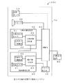
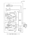
図1は、本発明の第1の実施の形態のアイリスを用いた個人認識装置を含む自動取引システムのブロック図である。
【0011】
この自動取引システム100は、アイリスを用いた個人認識装置70と、銀行などの自動取引装置80とを具備して構成される。
前記アイリスを用いた個人認識装置70は、対象者の接近を感知する近接センサ10と、対象者に対して指示をするためのスピーカ20と、対象者の画像を取得しその画像から対象者の眼の位置情報を抽出する人物画像取得部30と、前記対象者の眼の位置情報に基づいて対象者の眼の画像を取得しその眼の画像から対象者のアイリスパターンを抽出する眼画像取得部40と、前記対象者のアイリスパターンを予め登録されたアイリスパターンと照合するアイリス照合部50と、各部を制御するとともに前記アイリスパターンの照合の結果に基づいて前記自動取引装置80を利用する権利を対象者に与える制御部60とを具備して構成される。
【0012】
前記人物画像取得部30は、前方を撮影しかつ前後,左右または上下の少なくとも一つの方向に移動可能な可動式広角カメラ31と、前記可動式広角カメラ31の移動を制御する広角カメラ制御部32と、前記可動式広角カメラ31で取得した画像を分析し対象者の位置情報および眼の位置情報を取得する人物画像分析部33とを具備して構成される。
【0013】
前記眼画像取得部40は、前記人物画像分析部33で取得した対象者の眼の位置情報に基づいて望遠カメラ41を対象者の眼の位置にフォーカスする望遠カメラ制御部42と、前記望遠カメラ41で取得した対象者の眼の画像を分析し対象者のアイリスパターンを抽出する眼画像分析部43とを具備して構成される。
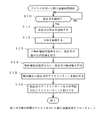
上記アイリスを用いた個人認識装置70は、図2に示すフローチャートに基づいて対象者の個人認識を行う。なお、動作開始時には、近接センサ10以外の各部の電源を切って、システムをパワーダウンモードとする。
【0014】
ステップS10では、近接センサ10により対象者の接近を感知しつづけ、対象者の接近を感知した場合はステップS11に進む。
ステップS11では、近接センサ10は、対象者の接近を制御部60に通知する。
ステップS12では、制御部60は、各部の電源を入れ、システムを起動する。
【0015】
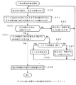
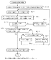
ステップS13では、人物画像取得部30は、図3に示すように、人物画像取得処理を行い、対象者の眼の位置情報を得る。
図3のステップS20では、図4に示すように、可動式広角カメラ31で対象者Pを撮影し、対象者画像を得る。なお、図4の(a)は横から見た図であり、図4の(b)は上から見た図である。図中の一点線は、可動式広角カメラ31の画界を示す。
【0016】
ステップS21では、人物画像分析部33は、可動式広角カメラ31の現在の位置に対応する基準画像を呼び出し、その基準画像と前記対象者画像と差分画像を求める。なお、前記基準画像とは、対象者がいないときに、予め可動式広角カメラ31で撮影した画像である。
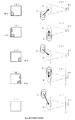
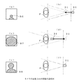
ステップS22では、人物画像分析部33は、前記差分画像の分布の評価を行い、その差分画像の分布は画像の中央かを判定する。図5の(a),(c),(e),(g),(i)に示すように、差分画像の分布は画像の中央でないならステップS23に進み、図6の(a),(c),(e)に示すように、差分画像の分布は画像の中央ならステップS24に進む。なお、人物画像分析部33は、例えば、前記差分画像をあらゆる分布を持つ複数のテンプレートと比較して前記差分画像の分布の評価を行う。
【0017】
ステップS23では、人物画像分析部33は制御部60に差分画像の分布情報を通知し、制御部60は、スピーカ20を介して、対象者に、図5の(b),(d),(f),(h),(j)に示すように、可動式広角カメラ31の画界の中央に移動するように指示して、動作を上記ステップS20に戻す。
なお、制御部60は、差分画像の分布が図5の(a)に示すような分布B1の場合は対象者Pが可動式広角カメラ31の画界に対して遠くてかつ左側に寄っていると判断し、図5の(b)に示すように、対象者Pに前方かつ左側に移動するように指示をする。また、制御部60は、差分画像の分布が図5の(c)に示すような分布B2の場合は対象者Pが可動式広角カメラ31の画界に対して左側に寄っていると判断し、図5の(d)に示すように、対象者Pに左側に移動するように指示をする。また、制御部60は、差分画像の分布が図5の(e)に示すような分布B3の場合は対象者Pが可動式広角カメラ31の画界に対して遠くてかつ右側に寄っていると判断し、図5の(f)に示すように、対象者Pに前方かつ右側に移動するように指示をする。また、制御部60は、差分画像の分布が図5の(g)に示すような分布B4の場合は対象者Pが可動式広角カメラ31の画界に対して遠くてかつ右側に寄っていると判断し、図5の(f)に示すように、対象者Pに前方かつ右側に移動するように指示をする。また、制御部60は、差分画像の分布が図5の(i)に示すような場合は対象者Pが可動式広角カメラ31の画界から外れていると判断し、図5の(f)に示すように、対象者Pに可動式広角カメラ31の画界の中央に移動するように指示をする。
【0018】
図3に戻って、ステップS24では、人物画像分析部33は、差分画像の分布が対象者Pの顔および眼の位置を検出できる分布かを判定する。図6の(a),(b)に示すように、差分画像の分布が対象者の顔および眼の位置を検出できる分布でないならステップS25に進み、図6の(e)に示すように、差分画像の分布が顔および眼の位置を検出できる分布ならステップS28に進む。なお、人物画像分析部33は、例えば、前記差分画像を図7に示すようなテンプレートと比較することによりその差分画像の分布が対象者の顔および眼の位置を検出できる分布かを判定する。
【0019】
ここで取得した画像から対象者の眼の位置情報を取得する方法としては、図7に示すようなテンプレートを用いたテンプレートマッチング手法による方法が考えられる。なお、対象者の眼の位置情報が得られない画像とは、例えば、対象者の頭部の一部が欠けている(図5参照)場合の画像である。
ステップS25では、制御部60は、可動式広角カメラ31の移動は可能かを判定する。可動式広角カメラ31の移動は可能ならステップS26に進み、可動式広角カメラ31の移動は可能でないなら、ステップS27に進む。
【0020】
ステップS26では、制御部60は、広角カメラ制御部32により、図6の(b),(d)に示すように、可動式広角カメラ31を移動して、動作を上記ステップS20に戻す。
なお、制御部60は、差分画像の分布が図6の(a)に示すような分布B6の場合は対象者Pが可動式広角カメラ31から著しく遠く離れていると判断し、図6の(b)に示すように、可動式広角カメラ31を前方に移動する。また、制御部60は、差分画像の分布が図6の(c)に示すような分布B7の場合は対象者Pが可動式広角カメラ31に著しく近いと判断し、図6の(d)に示すように、可動式広角カメラ31を後方に移動する。
【0021】
ステップS27では、制御部60はスピーカ20を介して、対象者に、可動式広角カメラ31の画界の中央に移動するように指示して、動作を上記ステップS20に戻す。
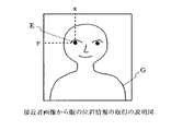
ステップ28では、人物画像取得部33は、図8に示すように、対象者画像から眼の位置(x,y)を抽出し、可動式広角カメラ31の現在の位置に応じた座標変換を施した眼の位置(x1,y1)を望遠カメラ制御部42に通知する。なお、図8では、対象者の右の眼の位置を抽出するように図示したが、左の眼の位置を抽出するまたは両眼の位置を抽出するようにしてもよい。
【0022】
図2に戻って、ステップS14では、眼画像取得部40は、対象者の眼画像取得処理を行い、対象者の眼画像を得る。なお、眼画像取得処理において、望遠カメラ制御部42は、前記対象者の眼の位置(x1,y1)に望遠カメラ41をフォーカスして撮影し、対象者の眼画像を得る。
ステップS15では、眼画像分析部43は、対象者の前記眼画像をコード化して、対象者のアイリスパターンを抽出し、アイリス照合部50に渡す。
【0023】
ステップS16では、アイリス照合部50は、対象者の前記アイリスパターンを予め登録されているアイリスパターンと照合し、その結果を制御部60に通知する。
制御部60は、対象者の前記アイリスパターンが予め登録されているアイリスパターンと一致した場合は対象者を利用者と判断し、その利用者に自動取引装置70を利用できるようにする。一方、対象者の前記アイリスパターンが予め登録されているアイリスパターンと一致しない場合は対象者に自動取引装置70を利用できないようにする。
【0024】
上記自動取引システム100によれば、対象者Pの画像中の位置に基づいて対象者の立ち位置を求め、その対象者Pが可動式広角カメラ31の画界の中央に立っていない場合は可動式広角カメラ31を移動する、また、可動式広角カメラ31を移動しても、対象者Pが可動式広角カメラ31の画界の中央に位置しない場合はその対象者Pに可動式広角カメラ31の画界の中央に移動するように指示をする。このため、従来と同じ解像度のカメラを用いても広い画界を得ることができるようになるから、背の高い対象者や、背の低い対象者や、左右に寄っている対象者や、カメラに近いまたは遠い対象者にも対応できることとなる。また、対象者の接近を感知したときのみシステムを起動し、対象者の接近を感知しないときはシステムをパワーダウンモードとすることにより、小電力化を実現できることとなる。
【0025】
また、上記実施の形態では、可動式広角カメラ31を移動し、望遠カメラ41を固定としたが、可動式広角カメラ31と望遠カメラ41の両方を可動式とし、可動式広角カメラ31を移動した分だけ望遠カメラ41をも移動するようにすれば、眼の位置の座標変換が不要となる。
また、上記実施の形態では、可動式広角カメラ31を前後方向に移動するように説明したが、図9に示すように、可動式広角カメラ31を横方向に移動するようにしてもよい。これにより、可動式広角カメラ31の画界を横方向に広げることができることとなる。例えば、差分画像の分布が図9の(a)に示すような分布B1の場合は対象者Pが可動式広角カメラ31の画界に対して遠くてかつ左側に寄っていると判断し、図9の(b)に示すように、可動式広角カメラ31を左前に移動する。また、差分画像の分布が図9の(c)に示すような分布B2の場合は対象者Pが可動式広角カメラ31の画界に対して左側に寄っていると判断し、図9の(d)に示すように、可動式広角カメラ31を左側に移動する。
【0026】
また、上記実施の形態では、可動式広角カメラ31を前後に移動するように説明したが、可動式広角カメラ31を上下方向に移動するようにしてもよい。これにより、可動式広角カメラ31の画界を上下方向に広げることができることとなる。
また、上記実施の形態では、可動式広角カメラ31を移動するように説明したが、可動式広角カメラ31を固定としかつ首振り動作により画界の向きを変えるようにしてもよい。また、可動式広角カメラ31を固定としかつそのレンズを切り替えることにより画界を変えるようにしてもよい。また、可動式広角カメラ31を固定かつズームカメラとし、そのズームを調整することにより画界を変えるようにしてもよい。これらにより、可動式広角カメラ31を移動するためのスペースが不要となるから、装置規模の縮小化および小スペース化を実現できることとなる。
【0027】
また、上記実施の形態では、スピーカを介して対象者に移動の指示をするように説明したが、表示板を用いて対象者に移動の指示をするようにしてもよい。
−第2の実施の形態−
図10は、本発明の第2の実施の形態のアイリスを用いた個人認識装置を含む自動取引システムのブロック図である。
【0028】
この自動取引システム200は、アイリスを用いた個人認識装置270と、銀行などの自動取引装置80からなる。
前記アイリスを用いた個人認識装置270は、上記自動取引システム100の人物画像取得部30の代わりに人物画像取得部230を具備している。それ以外の構成は、上記自動取引システム100と同様であるため、その説明を省略する。
【0029】
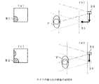
前記人物画像取得部30は、図11に示すように、前方からの光を反射しかつ前後方向に移動可能な可動式ミラー234と、前記可動式ミラー234からの反射光を受光することにより前方を撮影する広角カメラ231と、前記可動式ミラー234の移動を制御するミラー制御部232と、前記広角カメラ231で取得した画像を分析し対象者の位置情報および眼の位置情報を取得する人物画像分析部33とを具備して構成される。図11の(a)は横から見た図であり、図11の(b)は上から見た図である。
【0030】
なお、制御部60は、差分画像の分布が図12の(a)に示すような分布B6の場合は対象者Pが可動式ミラー234から著しく遠く離れていると判断し、図12の(b)に示すように、可動式ミラー234を前方に移動する。また、制御部60は、差分画像の分布が図12の(c)に示すような分布B7の場合は対象者Pが可動式ミラー234に著しく近いと判断し、図12の(d)に示すように、可動式ミラー234を後方に移動する。
【0031】
上記では、可動式ミラー234を前後方向に移動するように説明したが、2つのミラーを組み合わせ、1つのミラーを固定とし、他方のミラーを横方向や上下方向に移動することにより広角カメラの画界を横方向や上下方向に変えるようにしてもよい。
上記自動取引システム200によれば、対象者Pの画像中の位置に基づいて対象者の立ち位置を求め、その対象者Pが広角カメラ231の画界の中央に立っていない場合は可動式ミラー234を移動する、また、可動式ミラー234を移動しても、対象者Pが広角カメラ231の画界の中央に位置しない場合はその対象者Pに可動式ミラー234の画界の中央に移動するように指示をする。このため、従来と同じ解像度のカメラを用いても広い画界を得ることができるようになるから、背の高い対象者や、背の低い対象者や、左右に寄っている対象者や、カメラに近いまたは遠い対象者にも対応できることとなる。また、移動するのはカメラではなくミラーであるため、ケーブル類の移動が不要となり、機構の簡略化をできることとなる。
−第3の実施の形態−
図13は、本発明の第3の実施の形態のアイリスを用いた個人認識装置を含む自動取引システムのブロック図である。
【0032】
この自動取引システム300は、アイリスを用いた個人認識装置370と、銀行などの自動取引装置80からなる。
前記アイリスを用いた個人認識装置370は、上記自動取引システム100の近接センサ10の代わりに、対象者の接近を感知するとともにその対象者までの距離を検出する近接距離センサ310を具備している。それ以外の構成は、上記自動取引システム100と同様であるため、その説明を省略する。
【0033】
上記アイリスを用いた個人認識装置70は、図14に示すフローチャートに基づいて対象者の個人認識を行う。なお、動作開始時には、近接距離センサ310以外の各部の電源を切って、システムをパワーダウンモードとする。
ステップS10では、近接距離センサ310により対象者の接近を感知しつづけ、対象者の接近を感知した場合はステップS31に進む。
【0034】
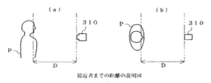
ステップS31では、近接距離センサ310は、図15に示すように、対象者までの距離Dを求め、制御部60に通知する。なお、図15の(a)は横から見た図であり、図15の(b)は上から見た図である。
ステップS12では、制御部60は、各部の電源を入れ、システムを起動する。
【0035】
ステップS13では、人物画像取得部30は、図16に示すように人物画像取得処理を行い、対象者の眼の位置情報を得る。
図16のステップS32では、制御部60は、対象者までの距離Dに基づいて、対象者Pが可動式広角カメラ31の画界の中央に位置するようにその可動式広角カメラ31を移動する。
【0036】
ステップS20では、可動式広角カメラ31で対象者Pを撮影し、対象者画像を得る。なお、それ以外の動作は、上記図3のフローチャートと同様であるため、その説明を省略する。
また、図14のステップ14からステップ17の動作は、図3のフローチャートのステップ14からステップ17の動作と同様であるため、その説明を省略する。
【0037】
上記自動取引システム300によれば、対象者Pまでの距離を求め、その距離に基づいて可動式広角カメラ31を移動する、また、可動式広角カメラ31を移動しても、対象者Pが可動式広角カメラ31の画界の中央に位置しない場合はその対象者Pに可動式広角カメラ31の画界の中央に移動するように指示をする。このため、従来と同じ解像度のカメラを用いても広い画界を得ることができるようになるから、背の高い対象者や、背の低い対象者や、左右に寄っている対象者や、カメラに近いまたは遠い対象者にも対応できることとなる。また、対象者Pまでの距離に基づいてカメラを予め移動させることができるため、差分画像の分布の評価に掛かる時間を短縮でき、個人認識作業の高速化を実現できることとなる。
−第4の実施の形態−
図17は、本発明の第4の実施の形態のアイリスを用いた個人認識装置を含む自動取引システムのブロック図である。
【0038】
この自動取引システム400は、アイリスを用いた個人認識装置470と、銀行などの自動取引装置80からなる。
前記アイリスを用いた個人認識装置470は、上記自動取引システム100の近接センサ10の代わりに、対象者の接近を感知するとともにその対象者の可動式広角カメラに対する位置を検出する近接位置センサ410を具備している。それ以外の構成は、上記自動取引システム100と同様であるため、その説明を省略する。
【0039】
近接位置センサ410は、例えば、ドアマット型加圧検出センサであり、図18に示すように、対象者Pがその上に立つと対象者Pの体重によってかかる圧力に基づいて対象者Pの位置(x2,y2)を制御部60に通知する。そして、制御部60は、対象者Pの位置(x2,y2)に基づいて、対象者Pが可動式広角カメラ31の画界の中央に位置するように可動式広角カメラ31を移動する。
【0040】
上記自動取引システム400によれば、対象者Pの位置(x2,y2)を検出し、その位置(x2,y2)に基づいて可動式広角カメラ31を移動する、また、可動式広角カメラ31を移動しても、対象者Pが可動式広角カメラ31の画界の中央に位置しない場合はその対象者Pに可動式広角カメラ31の画界の中央に移動するように指示をする。このため、従来と同じ解像度のカメラを用いても広い画界を得ることができるようになるから、背の高い対象者や、背の低い対象者や、左右に寄っている対象者や、カメラに近いまたは遠い対象者にも対応でき背の高い対象者や、背の低い対象者や、左右に寄っている対象者にも対応できることとなる。また、対象者Pの位置に基づいてカメラを予め移動させることができるため、差分画像の分布の評価に掛かる時間を短縮でき、個人認識作業の高速化を実現できることとなる。
【0041】
【発明の効果】
以上説明したように、本発明のアイリスを用いた個人認識装置は、前方を撮影しかつ前後,左右または上下の少なくとも一つの方向の所定の位置までに少なくとも一つの段階で移動可能な可動式広角カメラを設け、その可動式広角カメラで取得した対象者の画像中の位置に基づいて対象者の立ち位置を求め、その対象者が可動式広角カメラの画界の中央に立っていない場合は可動式広角カメラを移動し、可動式広角カメラを移動しても対象者が可動式広角カメラの画界の中央に位置しない場合は対象者に可動式広角カメラの画界の中央に移動するように指示をする。このため、従来と同じ解像度のカメラを用いても広い画界を得ることができるようになるから、背の高い対象者や、背の低い対象者や、左右に寄っている対象者や、カメラに近いまたは遠い対象者にも対応でき、個人認識作業の高速化を実現できることとなる。
【0042】
また、近接センサを設け、対象者の接近を感知したときのみシステムを起動し、対象者の接近を感知しないときはシステムをパワーダウンモードとすることにより、小電力化を実現できることとなる。
また、以上説明したように、本発明の自動取引システムは、上記構成のアイリスを用いた個人認識装置と、自動取引装置を具備し、そのアイリスを用いた個人認識装置で行った個人認識に基づいて対象者に自動取引装置を利用する権利を与えるまたは拒否する。これにより、解像度を保ちながら広い画界を得ることができ、個人認識作業をやり直す必要がなくなるから、利用者にかかる負担を軽減できる。
【図面の簡単な説明】
【図1】本発明の第1の実施の形態のアイリスを用いた個人認識装置を含む自動取引システムのブロック図である。
【図2】本発明の第1の実施の形態のアイリスを用いた個人認識処理を示すフローチャートである。
【図3】本発明の第1の実施の形態の人物画像取得処理を示すフローチャートである。
【図4】図1のアイリスを用いた個人認識装置における対象者の撮影の説明図である。
【図5】差分画像の分布に基づく対象者の移動の説明図である。
【図6】差分画像の分布に基づく可動式広角カメラの移動の説明図である。
【図7】テンプレートの例示図である。
【図8】対象者画像から眼の位置情報の取得の説明図である。
【図9】可動式広角カメラの横方向の移動の説明図である。
【図10】本発明の第2の実施の形態のアイリスを用いた個人認識装置を含む自動取引システムのブロック図である。
【図11】可動式ミラーおよび固定広角カメラによる対象者の撮影の説明図である。
【図12】差分画像の分布に基づく可動式ミラーの移動の説明図である。
【図13】本発明の第3の実施の形態のアイリスを用いた個人認識装置を含む自動取引システムのブロック図である。
【図14】本発明の第3の実施の形態のアイリスを用いた個人認識処理を示すフローチャートである。
【図15】近接距離センサにおける対象者までの距離の検出の説明図である。
【図16】本発明の第3の実施の形態の人物画像取得処理を示すフローチャートである。
【図17】本発明の第4の実施の形態のアイリスを用いた個人認識装置を含む自動取引システムのブロック図である。
【図18】近接位置センサにおける対象者までの位置の検出の説明図である。
【図19】従来の広角カメラよる対象者の撮影の説明図である。
【図20】従来の広角カメラにおける問題点の説明図である。
【符号の説明】
100,200,300,400 自動取引システム
70,270,370,470 アイリスを用いた個人認識装置
10 近接センサ
310 近接距離センサ
410 近接位置センサ
31 可動式広角カメラ
234 可動式ミラー[0001]
TECHNICAL FIELD OF THE INVENTION
The present invention relates to a personal recognition device using an iris that performs personal recognition using a unique feature of a human iris (hereinafter, referred to as an iris), and an ATM (hereinafter, an automatic transaction device) provided to a person recognized as a user. And an automatic transaction system that gives a right to use a computer or the like.
[0002]
[Prior art]
As a conventional personal recognition device using an iris, as shown in FIG. 19, an image of a subject P is acquired by a fixed wide-angle camera WF, an eye position in the image is obtained, and a telephoto position is obtained from the eye position. An image of the subject's eye is obtained by focusing on the camera NF. Then, the iris pattern of the subject is extracted from the image of the eye, and the iris pattern is compared with a pre-registered iris pattern to determine whether the subject is a user.
[0003]
In addition, the right to use, for example, an automatic transaction device of a bank or a computer is granted to a person determined to be a user.
[0004]
[Problems to be solved by the invention]
In the above-mentioned conventional personal recognition device using an iris, a subject is photographed by a fixed wide-angle camera, and the position of the subject's eyes is acquired.
However, the wide-angle camera has a limitation on the field of view depending on the lens and a limitation on the resolution depending on the CCD. Therefore, for example, when a tall subject PT shown in FIG. 20A or a short subject PS shown in FIG. Of the subject's field of view, and the position of the subject's eye cannot be acquired. In order to solve this problem, conventionally, the line of sight of the wide-angle camera is set to be relatively high so as to match a tall subject, and a step platform having a different height is used for a short subject. In addition, when the standing position of the subject is extremely far or very close, or when the subject is moving right and left, the administrator has instructed the standing position of the subject and performed the operation again.
[0005]
Note that if a wide-angle camera with a wide field of view is used, sufficient resolution cannot be obtained, so that the position of the eye cannot be obtained from the image.
Accordingly, an object of the present invention is to provide a personal recognition device using an iris that can obtain an image of a wider field of view while maintaining a sufficient resolution.
[0006]
[Means for Solving the Problems]
In order to achieve the above object, the present invention provides a movable camera capable of photographing the front and moving to a predetermined position in at least one of the front, rear, left, right, and up and down directions, and an image obtained by the movable camera. Target person position information obtaining means for obtaining the target person's position information, determining means for determining whether or not the target person's eye position information can be obtained from the obtained image, and obtaining the target person's eye position information If not, the movable camera control means for moving the movable camera so that the subject is reflected near the center of the image, and the position of the subject's eyes even if the movable camera is moved to the predetermined position. Instruction means for instructing the subject to move to the vicinity of the center of the imaging area of the movable camera when information acquisition is not possible; and Of the eye of the Eye position information obtaining means for obtaining placement information, a camera for obtaining a subject's eye image based on the eye position information, an iris pattern extraction means for extracting a subject's iris pattern from the eye image, An iris pattern matching means for determining whether or not the target person is a user by comparing the iris pattern of the target person with an iris pattern registered in advance; and providing an individual recognition device using the iris. I do.
[0007]
In the personal recognition device using the iris, for example, when the subject is present at the bottom of the image, the subject is determined to be short and the movable wide-angle camera is moved downward. If the subject is close to the camera, move the movable wide-angle camera backward if the subject is close to the camera, and move the movable wide-angle camera sideways if the subject is right or left of the image. Move in the direction. If the subject is not located near the center of the image even after moving the movable wide-angle camera, the subject is instructed to move near the center of the field of view of the movable wide-angle camera. . For this reason, a wide field of view can be obtained even with a camera having the same resolution as before, so that a tall subject, a short subject, a subject leaning right and left, and a camera It is possible to cope with a subject close to or far from the target.
[0008]
Further, the present invention provides a personal recognition device using the iris having the above-described configuration, wherein a proximity sensor for detecting approach of a target person, each unit is set to a power down mode, and each unit is set only when the proximity sensor detects the approach of the target person. Provided is a personal recognition device using an iris, comprising a control unit for starting.
In the personal recognition device using the iris, since the power down mode is set when the target person does not approach, the power consumption can be reduced.
[0009]
Further, in order to achieve the above object, the present invention provides a personal recognition device using the iris having the above configuration, an automatic transaction device, and the iris pattern matching unit when the iris pattern matching unit determines that the target person is a user. An interface for giving a right to use the automatic transaction apparatus.
In the automatic transaction system, a wider field of view can be obtained while maintaining the resolution, and there is no need to perform the individual recognition operation again, so that the burden on the user can be reduced.
[0010]
BEST MODE FOR CARRYING OUT THE INVENTION
Hereinafter, the present invention will be described in more detail with reference to the embodiments shown in the drawings. Note that the present invention is not limited to this.
-1st Embodiment-
FIG. 1 is a block diagram of an automatic transaction system including a personal recognition device using an iris according to a first embodiment of the present invention.
[0011]
The
The
[0012]
The person
[0013]
The eye
The
[0014]
In step S10, the approach of the target person is continuously detected by the
In step S11, the
In step S12, the
[0015]
In step S13, as shown in FIG. 3, the person
In step S20 in FIG. 3, as shown in FIG. 4, the subject P is photographed by the movable wide-
[0016]
In step S21, the person
In step S22, the person
[0017]
In step S23, the person
In addition, when the distribution of the difference image is the distribution B1 as illustrated in FIG. 5A, the
[0018]
Returning to FIG. 3, in step S24, the person
[0019]
As a method for acquiring the eye position information of the subject from the acquired image, a method using a template matching method using a template as shown in FIG. 7 can be considered. The image for which the position information of the subject's eyes cannot be obtained is, for example, an image in which a part of the subject's head is missing (see FIG. 5).
In step S25, the
[0020]
In step S26, the
In addition, when the distribution of the difference image is the distribution B6 as illustrated in FIG. 6A, the
[0021]
In step S27, the
In
[0022]
Returning to FIG. 2, in step S14, the eye
In step S15, the eye
[0023]
In step S16, the
When the iris pattern of the target person matches the iris pattern registered in advance, the
[0024]
According to the
[0025]
In the above-described embodiment, the movable wide-
Further, in the above-described embodiment, the movable wide-
[0026]
Further, in the above-described embodiment, the movable wide-
In the above-described embodiment, the movable wide-
[0027]
Further, in the above embodiment, the movement instruction is given to the target person via the speaker. However, the movement instruction may be given to the target person using the display panel.
-2nd Embodiment-
FIG. 10 is a block diagram of an automatic transaction system including a personal recognition device using an iris according to the second embodiment of the present invention.
[0028]
The
The
[0029]
As shown in FIG. 11, the person
[0030]
When the distribution of the difference image is the distribution B6 as shown in FIG. 12A, the
[0031]
In the above description, the
According to the
-Third embodiment-
FIG. 13 is a block diagram of an automatic transaction system including a personal recognition device using an iris according to the third embodiment of the present invention.
[0032]
The
The
[0033]
The
In step S10, the approach of the target person is continuously detected by the
[0034]
In step S31, the
In step S12, the
[0035]
In step S13, the person
In step S32 of FIG. 16, the
[0036]
In step S20, the subject P is photographed by the movable wide-
Also, the operations in
[0037]
According to the
-Fourth embodiment-
FIG. 17 is a block diagram of an automatic transaction system including a personal recognition device using an iris according to the fourth embodiment of the present invention.
[0038]
The
The
[0039]
The
[0040]
According to the
[0041]
【The invention's effect】
As described above, the personal recognition device using the iris of the present invention is a movable wide-angle type which can photograph the front and move in at least one stage to a predetermined position in at least one direction of front and rear, left and right or up and down. A camera is provided, and a standing position of the subject is obtained based on the position in the image of the subject acquired by the movable wide-angle camera, and if the subject is not standing in the center of the field of view of the movable wide-angle camera, it is movable. If the subject is not located at the center of the field of view of the movable wide-angle camera even after moving the movable wide-angle camera and moving the movable wide-angle camera, the subject is moved to the center of the field of view of the movable wide-angle camera. Give instructions. For this reason, a wide field of view can be obtained even with a camera having the same resolution as before, so that a tall subject, a short subject, a subject leaning right and left, and a camera Therefore, it is possible to cope with a subject close to or far from the target, and to realize a high-speed personal recognition operation.
[0042]
Further, by providing a proximity sensor and activating the system only when the approach of the target person is sensed, and by setting the system to the power down mode when the approach of the target person is not sensed, it is possible to reduce power consumption.
Further, as described above, the automatic transaction system of the present invention includes the personal recognition device using the iris configured as described above, and an automatic transaction device, and is based on the personal recognition performed by the personal recognition device using the iris. Grant or deny the right to use the automated teller to the subject. As a result, a wide field of view can be obtained while maintaining the resolution, and it is not necessary to perform the individual recognition work again, so that the burden on the user can be reduced.
[Brief description of the drawings]
FIG. 1 is a block diagram of an automatic transaction system including a personal recognition device using an iris according to a first embodiment of the present invention.
FIG. 2 is a flowchart illustrating a personal recognition process using an iris according to the first embodiment of this invention.
FIG. 3 is a flowchart illustrating a human image acquisition process according to the first embodiment of this invention.
FIG. 4 is an explanatory diagram of imaging of a target person in the personal recognition device using the iris of FIG. 1;
FIG. 5 is an explanatory diagram of movement of a target person based on the distribution of difference images.
FIG. 6 is an explanatory diagram of movement of a movable wide-angle camera based on distribution of a difference image.
FIG. 7 is an illustration of a template.
FIG. 8 is an explanatory diagram of acquiring eye position information from a subject image.
FIG. 9 is an explanatory diagram of a lateral movement of a movable wide-angle camera.
FIG. 10 is a block diagram of an automatic transaction system including a personal recognition device using an iris according to a second embodiment of the present invention.
FIG. 11 is an explanatory diagram of imaging of a subject by a movable mirror and a fixed wide-angle camera.
FIG. 12 is an explanatory diagram of movement of a movable mirror based on distribution of a difference image.
FIG. 13 is a block diagram of an automatic transaction system including a personal recognition device using an iris according to a third embodiment of the present invention.
FIG. 14 is a flowchart illustrating a personal recognition process using an iris according to the third embodiment of this invention.
FIG. 15 is an explanatory diagram of detection of a distance to a target person by a proximity distance sensor.
FIG. 16 is a flowchart illustrating a person image acquisition process according to the third embodiment of this invention.
FIG. 17 is a block diagram of an automatic transaction system including a personal recognition device using an iris according to a fourth embodiment of the present invention.
FIG. 18 is an explanatory diagram of detection of a position up to a target person by a proximity position sensor.
FIG. 19 is an explanatory diagram of photographing of a subject by a conventional wide-angle camera.
FIG. 20 is an explanatory diagram of a problem in a conventional wide-angle camera.
[Explanation of symbols]
100, 200, 300, 400 Automatic trading system
70, 270, 370, 470 Individual recognition device using iris
10 Proximity sensor
310 Proximity distance sensor
410 Proximity position sensor
31 Movable wide-angle camera
234 Movable mirror
Claims (11)
前記眼の位置情報に基づいて対象者の眼画像を取得するカメラと、前記眼画像から対象者のアイリスパターンを抽出するアイリスパターン抽出手段と、前記対象者のアイリスパターンを予め登録したアイリスパターンと照合することにより前記対象者が利用者か否かを判断するアイリスパターン照合手段とを具備したことを特徴とするアイリスを用いた個人認識装置。A movable camera capable of photographing the front and moving to a predetermined position in at least one of the front, rear, left and right, and up and down directions, and a subject position for acquiring position information of the subject based on an image acquired by the movable camera Information obtaining means, determining means for determining whether or not positional information of the eye of the target person can be obtained from the obtained image, and when the positional information of the eye of the target person cannot be obtained, the target person is located near the center of the image. A movable camera control means for moving the movable camera so that the movable camera is moved to the predetermined position even if the movable camera is moved to the predetermined position. Instruction means for instructing movement of the movable camera to the vicinity of the center of the imaging area; and eye position for obtaining position information of the subject's eye from the image when position information of the subject's eye can be obtained. Information acquisition hands And,
A camera that acquires a subject's eye image based on the eye position information, an iris pattern extraction unit that extracts a subject's iris pattern from the eye image, and an iris pattern in which the subject's iris pattern is registered in advance. An iris-based personal recognition device, comprising: an iris pattern matching unit that determines whether or not the target person is a user by checking.
前記眼の位置情報に基づいて対象者の眼画像を取得するカメラと、前記眼画像から対象者のアイリスパターンを抽出するアイリスパターン抽出手段と、前記対象者のアイリスパターンを予め登録したアイリスパターンと照合することにより前記対象者が利用者か否かを判断するアイリスパターン照合手段とを具備したことを特徴とするアイリスを用いた個人認識装置。A movable reflecting means movable to a predetermined position in at least one of the front, rear, left and right or up and down directions; a fixed camera for photographing the front by receiving reflected light from the movable reflecting means; A subject position information acquiring unit that acquires position information of the subject based on the acquired image; a determining unit that determines whether or not positional information of the subject's eye can be obtained from the acquired image; When it is not possible to obtain the position information, the reflection control means for moving the movable reflecting means so that the subject is reflected near the center of the image, and the movable reflecting means may be moved to the predetermined position. Instructing means for instructing the subject to move to the vicinity of the center of the imaging area of the fixed camera when position information of the eye of the target person is not possible, and when position information of the eye of the target person is obtainable Before And the eye position information obtaining means for obtaining position information of the eye of the subject from an image,
A camera that acquires a subject's eye image based on the eye position information, an iris pattern extraction unit that extracts a subject's iris pattern from the eye image, and an iris pattern in which the subject's iris pattern is registered in advance. An iris-based personal recognition device, comprising: an iris pattern matching unit that determines whether or not the target person is a user by checking.
前記眼の位置情報に基づいて対象者の眼画像を取得するカメラと、前記眼画像から対象者のアイリスパターンを抽出するアイリスパターン抽出手段と、前記対象者のアイリスパターンを予め登録したアイリスパターンと照合することにより前記対象者が利用者か否かを判断するアイリスパターン照合手段とを具備したことを特徴とするアイリスを用いた個人認識装置。A fixed camera that can shoot the front and control a shooting area by zooming or switching lenses, a subject position information obtaining unit that obtains position information of a subject based on an image obtained by the fixed camera, and Determining means for determining whether or not position information of the subject's eyes can be obtained; and photographing of the fixed camera so that the subject is displayed near the center of the image when position information of the subject's eyes is not available. Fixed camera control means for controlling the area, and instructing means for instructing the subject to move to the vicinity of the center of the shooting area of the fixed camera when the control of the shooting area of the fixed camera is limited, Eye position information acquisition means for acquiring position information of the eye of the target person from the image when position information acquisition of the eye of the target person is possible,
A camera that acquires a subject's eye image based on the eye position information, an iris pattern extraction unit that extracts a subject's iris pattern from the eye image, and an iris pattern in which the subject's iris pattern is registered in advance. An iris-based personal recognition device, comprising: an iris pattern matching unit that determines whether or not the target person is a user by checking.
前記眼の位置情報に基づいて対象者の眼画像を取得するカメラと、前記眼画像から対象者のアイリスパターンを抽出するアイリスパターン抽出手段と、前記対象者のアイリスパターンを予め登録したアイリスパターンと照合することにより前記対象者が利用者か否かを判断するアイリスパターン照合手段とを具備したことを特徴とするアイリスを用いた個人認識装置。A distance sensor for detecting a distance to the target person, a movable camera capable of photographing ahead and moving to a predetermined position in at least one of the front, rear, left, right, and up and down directions, and a target based on the distance to the target person Movable camera control means for moving the movable camera so that the user is near the center of the shooting area; and subject position information acquisition for acquiring subject position information based on images acquired by the movable camera. Means for determining whether or not the position information of the eye of the target person can be obtained from the acquired image, and when the position information of the eye of the target person cannot be obtained, the target person appears near the center of the image. When the movable camera is moved by the movable camera control means and the movable camera is moved to the predetermined position, position information of the eye of the subject cannot be obtained. Instruction means for instructing to move to the vicinity of the center of the shooting area of the expression camera, and eye position information for obtaining position information of the subject's eye from the image when position information of the subject's eye is obtainable Acquisition means;
A camera that acquires a subject's eye image based on the eye position information, an iris pattern extraction unit that extracts a subject's iris pattern from the eye image, and an iris pattern in which the subject's iris pattern is registered in advance. An iris-based personal recognition device, comprising: an iris pattern matching unit that determines whether or not the target person is a user by checking.
前記眼の位置情報に基づいて対象者の眼画像を取得するカメラと、前記眼画像から対象者のアイリスパターンを抽出するアイリスパターン抽出手段と、前記対象者のアイリスパターンを予め登録したアイリスパターンと照合することにより前記対象者が利用者か否かを判断するアイリスパターン照合手段とを具備したことを特徴とするアイリスを用いた個人認識装置。A distance sensor for detecting the distance to the subject, a movable reflecting means movable to a predetermined position in at least one of the front, rear, left and right or up and down directions, and receiving reflected light from the movable reflecting means A fixed camera for photographing the front, reflection control means for moving the movable reflecting means such that the subject is near the center of the photographing area based on the distance to the subject, and an image acquired by the fixed camera. Target position information obtaining means for obtaining position information of the target person based on the position information of the target person's eyes; determining means for obtaining position information of the target person's eyes from the obtained image; If acquisition is not possible, the reflection control means moves the movable reflection means so that the subject is reflected in the vicinity of the center of the image, and even if the movable reflection means is moved to the predetermined position, Instruction means for instructing the target person to move to the vicinity of the center of the shooting area of the fixed camera when the position information of the eye of the subject is not available; and Eye position information acquisition means for acquiring position information of the eye of the subject from the image,
A camera that acquires a subject's eye image based on the eye position information, an iris pattern extraction unit that extracts a subject's iris pattern from the eye image, and an iris pattern in which the subject's iris pattern is registered in advance. An iris-based personal recognition device, comprising: an iris pattern matching unit that determines whether or not the target person is a user by checking.
前記眼の位置情報に基づいて対象者の眼画像を取得するカメラと、前記眼画像から対象者のアイリスパターンを抽出するアイリスパターン抽出手段と、前記対象者のアイリスパターンを予め登録したアイリスパターンと照合することにより前記対象者が利用者か否かを判断するアイリスパターン照合手段とを具備したことを特徴とするアイリスを用いた個人認識装置。A distance sensor for detecting the distance to the subject, a fixed camera capable of taking a picture in front and controlling the shooting area by zooming or switching the lens, and a subject near the center of the shooting area based on the distance to the subject. Fixed camera control means for controlling an image capturing area of the fixed camera, subject position information acquiring means for acquiring position information of a subject based on an image acquired by the fixed camera, and an object from the acquired image. Determining means for determining whether or not the position information of the subject's eyes can be obtained, and when the position information of the subject's eyes cannot be obtained, the fixed camera control means so that the subject is shown near the center of the image. Controlling the shooting area of the fixed camera, and instructing the subject to move to the vicinity of the center of the shooting area of the fixed camera when the control of the shooting area of the fixed camera is limited. An instruction means for, and the eye position information obtaining means for obtaining position information of the eye of the subject from the image when the position information acquisition of the subject's eye is possible,
A camera that acquires a subject's eye image based on the eye position information, an iris pattern extraction unit that extracts a subject's iris pattern from the eye image, and an iris pattern in which the subject's iris pattern is registered in advance. An iris-based personal recognition device, comprising: an iris pattern matching unit that determines whether or not the target person is a user by checking.
前記眼の位置情報に基づいて対象者の眼画像を取得するカメラと、前記眼画像から対象者のアイリスパターンを抽出するアイリスパターン抽出手段と、前記対象者のアイリスパターンを予め登録したアイリスパターンと照合することにより前記対象者が利用者か否かを判断するアイリスパターン照合手段とを具備したことを特徴とするアイリスを用いた個人認識装置。A position sensor for detecting the standing position of the subject, a movable camera capable of photographing ahead and moving to a predetermined position in at least one of the front, rear, left, right, and up and down directions, and a target based on the standing position of the subject. Movable camera control means for moving the movable camera so that the user is near the center of the shooting area; and subject position information acquisition for acquiring subject position information based on images acquired by the movable camera. Means for determining whether or not the position information of the eye of the target person can be obtained from the acquired image, and when the position information of the eye of the target person cannot be obtained, the target person appears near the center of the image. When the movable camera is moved by the movable camera control means and the movable camera is moved to the predetermined position, position information of the eye of the subject cannot be obtained. Instruction means for instructing to move to the vicinity of the center of the shooting area of the expression camera, and eye position information for obtaining position information of the subject's eye from the image when position information of the subject's eye is obtainable Acquisition means;
A camera that acquires a subject's eye image based on the eye position information, an iris pattern extraction unit that extracts a subject's iris pattern from the eye image, and an iris pattern in which the subject's iris pattern is registered in advance. An iris-based personal recognition device, comprising: an iris pattern matching unit that determines whether or not the target person is a user by checking.
前記眼の位置情報に基づいて対象者の眼画像を取得するカメラと、前記眼画像から対象者のアイリスパターンを抽出するアイリスパターン抽出手段と、前記対象者のアイリスパターンを予め登録したアイリスパターンと照合することにより前記対象者が利用者か否かを判断するアイリスパターン照合手段とを具備したことを特徴とするアイリスを用いた個人認識装置。A position sensor for detecting a standing position of the subject, a movable reflecting means movable to a predetermined position in at least one of the front, rear, left and right or up and down directions, and receiving reflected light from the movable reflecting means A fixed camera for photographing the front, reflection control means for moving the movable reflecting means such that the subject is near the center of the photographing area based on the standing position of the subject, and an image acquired by the fixed camera Target position information obtaining means for obtaining position information of the target person based on the position information of the target person's eyes; determining means for obtaining position information of the target person's eyes from the obtained image; If acquisition is not possible, the reflection control means moves the movable reflection means so that the subject is reflected in the vicinity of the center of the image, and even if the movable reflection means is moved to the predetermined position, Instruction means for instructing the target person to move to the vicinity of the center of the shooting area of the fixed camera when the position information of the eye of the subject is not available; and Eye position information acquisition means for acquiring position information of the eye of the subject from the image,
A camera that acquires a subject's eye image based on the eye position information, an iris pattern extraction unit that extracts a subject's iris pattern from the eye image, and an iris pattern in which the subject's iris pattern is registered in advance. An iris-based personal recognition device, comprising: an iris pattern matching unit that determines whether or not the target person is a user by checking.
前記眼の位置情報に基づいて対象者の眼画像を取得するカメラと、前記眼画像から対象者のアイリスパターンを抽出するアイリスパターン抽出手段と、前記対象者のアイリスパターンを予め登録したアイリスパターンと照合することにより前記対象者が利用者か否かを判断するアイリスパターン照合手段とを具備したことを特徴とするアイリスを用いた個人認識装置。A position sensor for detecting the standing position of the subject, a fixed camera that can photograph the front and control the photographing region by zooming or switching the lens, and the subject can be positioned near the center of the photographing region based on the standing position of the subject. Fixed camera control means for controlling an image capturing area of the fixed camera, subject position information acquiring means for acquiring position information of a subject based on an image acquired by the fixed camera, and an object from the acquired image. Determining means for determining whether or not the position information of the subject's eyes can be obtained, and when the position information of the subject's eyes cannot be obtained, the fixed camera control means so that the subject is shown near the center of the image. Controlling the shooting area of the fixed camera, and instructing the subject to move to the vicinity of the center of the shooting area of the fixed camera when the control of the shooting area of the fixed camera is limited. An instruction means for, and the eye position information obtaining means for obtaining position information of the eye of the subject from the image when the position information acquisition of the subject's eye is possible,
A camera that acquires a subject's eye image based on the eye position information, an iris pattern extraction unit that extracts a subject's iris pattern from the eye image, and an iris pattern in which the subject's iris pattern is registered in advance. An iris-based personal recognition device, comprising: an iris pattern matching unit that determines whether or not the target person is a user by checking.
対象者の接近を感知する近接センサと、各部をパワーダウンモードとし前記近接センサにより対象者の接近を感知したときのみ各部を起動する制御部を具備したことを特徴とするアイリスを用いた個人認識装置。A personal recognition device using the iris according to claim 1,
Personal recognition using an iris, comprising: a proximity sensor for detecting approach of a target person; and a control unit for setting each unit to a power down mode and activating each unit only when the proximity sensor detects the approach of the target person. apparatus.
Priority Applications (1)
| Application Number | Priority Date | Filing Date | Title |
|---|---|---|---|
| JP30446896A JP3587635B2 (en) | 1996-11-15 | 1996-11-15 | Personal recognition device using iris and automatic transaction system using this personal recognition device |
Applications Claiming Priority (1)
| Application Number | Priority Date | Filing Date | Title |
|---|---|---|---|
| JP30446896A JP3587635B2 (en) | 1996-11-15 | 1996-11-15 | Personal recognition device using iris and automatic transaction system using this personal recognition device |
Publications (2)
| Publication Number | Publication Date |
|---|---|
| JPH10137223A JPH10137223A (en) | 1998-05-26 |
| JP3587635B2 true JP3587635B2 (en) | 2004-11-10 |
Family
ID=17933388
Family Applications (1)
| Application Number | Title | Priority Date | Filing Date |
|---|---|---|---|
| JP30446896A Expired - Fee Related JP3587635B2 (en) | 1996-11-15 | 1996-11-15 | Personal recognition device using iris and automatic transaction system using this personal recognition device |
Country Status (1)
| Country | Link |
|---|---|
| JP (1) | JP3587635B2 (en) |
Families Citing this family (20)
| Publication number | Priority date | Publication date | Assignee | Title |
|---|---|---|---|---|
| US6320610B1 (en) * | 1998-12-31 | 2001-11-20 | Sensar, Inc. | Compact imaging device incorporating rotatably mounted cameras |
| KR20010016241A (en) * | 2000-11-27 | 2001-03-05 | 김재희 | Automatic eye image acquisition method |
| KR100361141B1 (en) * | 2000-11-20 | 2002-11-21 | 주식회사 알파엔지니어링 | Access control method and installation using iris cognition |
| KR100430268B1 (en) * | 2001-03-15 | 2004-05-04 | 엘지전자 주식회사 | Focusing angle display of iris recognition system |
| US7271839B2 (en) | 2001-03-15 | 2007-09-18 | Lg Electronics Inc. | Display device of focal angle and focal distance in iris recognition system |
| KR100443674B1 (en) * | 2001-03-15 | 2004-08-09 | 엘지전자 주식회사 | Distance measuring method and apparatus of iris recognition system |
| KR100410972B1 (en) * | 2001-03-15 | 2003-12-18 | 엘지전자 주식회사 | Focusing distance display of iris recognition system |
| JP2003242490A (en) * | 2002-02-14 | 2003-08-29 | Omron Corp | Personal authentication device |
| JP2003296711A (en) | 2002-03-29 | 2003-10-17 | Nec Corp | Method, device and program for identifying facial image |
| KR100518866B1 (en) * | 2002-08-05 | 2005-09-30 | 엘지전자 주식회사 | An iris recognation apparatus and method for determining the distance of iris recognition |
| KR100493700B1 (en) * | 2002-10-02 | 2005-06-02 | 엘지전자 주식회사 | Automatic recognition method for iris recognition system |
| KR100547333B1 (en) * | 2003-03-17 | 2006-01-26 | 엘지전자 주식회사 | How to display the distance of the iris system |
| JP3860552B2 (en) | 2003-03-25 | 2006-12-20 | 富士通株式会社 | Imaging device |
| JP3879719B2 (en) * | 2003-08-22 | 2007-02-14 | 松下電器産業株式会社 | Image input device and authentication device using the same |
| US7593550B2 (en) | 2005-01-26 | 2009-09-22 | Honeywell International Inc. | Distance iris recognition |
| GB2406424A (en) | 2003-09-23 | 2005-03-30 | Ncr Int Inc | Biometric system provides feedback if the biometric capture was not complete |
| JP4963388B2 (en) * | 2006-09-12 | 2012-06-27 | 日立オムロンターミナルソリューションズ株式会社 | Biometric authentication device and operation guidance notification method |
| EP2565827A4 (en) | 2010-04-27 | 2014-04-02 | Dmitry Evgenievich Antonov | Device for producing images of irises of the eyes |
| WO2017051696A1 (en) * | 2015-09-24 | 2017-03-30 | 日本電産リード株式会社 | Iris authentication device |
| CN113757503B (en) * | 2021-08-18 | 2022-05-27 | 北京邮电大学 | A kind of facial biometric feature collection method and collection device |
Family Cites Families (3)
| Publication number | Priority date | Publication date | Assignee | Title |
|---|---|---|---|---|
| US4641349A (en) * | 1985-02-20 | 1987-02-03 | Leonard Flom | Iris recognition system |
| US5419513A (en) * | 1993-05-11 | 1995-05-30 | United Technologies Corporation | Ancillary aerodynamic structures for an unmanned aerial vehicle having ducted, coaxial counter-rotating rotors |
| US5572596A (en) * | 1994-09-02 | 1996-11-05 | David Sarnoff Research Center, Inc. | Automated, non-invasive iris recognition system and method |
-
1996
- 1996-11-15 JP JP30446896A patent/JP3587635B2/en not_active Expired - Fee Related
Also Published As
| Publication number | Publication date |
|---|---|
| JPH10137223A (en) | 1998-05-26 |
Similar Documents
| Publication | Publication Date | Title |
|---|---|---|
| JP3587635B2 (en) | Personal recognition device using iris and automatic transaction system using this personal recognition device | |
| US7574021B2 (en) | Iris recognition for a secure facility | |
| US7369759B2 (en) | Eye image pickup apparatus, iris authentication apparatus and portable terminal device having iris authentication function | |
| US6320610B1 (en) | Compact imaging device incorporating rotatably mounted cameras | |
| US20050084179A1 (en) | Method and apparatus for performing iris recognition from an image | |
| US7130453B2 (en) | Eye position detection method and device | |
| JP4265076B2 (en) | Multi-angle camera and automatic photographing device | |
| KR20040084994A (en) | Authentication object image pick-up device and method thereof | |
| EP1387314A1 (en) | Method and apparatus for picking up image of object being authenticated | |
| US11006864B2 (en) | Face detection device, face detection system, and face detection method | |
| EP1408446A1 (en) | Authentication object image-pickup method and device therefor | |
| JP3642336B2 (en) | Eye imaging device | |
| JP2003108983A (en) | Eye image pickup device, iris authentication device, and portable terminal device with iris authentication function | |
| JP2000163600A (en) | Face photographing and recognizing method and device | |
| CN101543409A (en) | Long-distance iris identification device | |
| WO2006129634A1 (en) | Eye image taking device and authentication device using the same | |
| JP2005258860A (en) | Multiple authentication method and apparatus | |
| JP2001005948A (en) | Iris imaging device | |
| KR101596363B1 (en) | Access Control Apparatus and Method by Facial Recognition | |
| EP4033400B1 (en) | System for acquiring iris image to enlarge iris recognition range | |
| JP2004295572A (en) | Authentication target image pickup apparatus and image pickup method thereof | |
| JP2011095985A (en) | Image display apparatus | |
| JP2021179890A (en) | Image recognition device, authentication system, image recognition method, and program | |
| KR20020038162A (en) | Iris recognition method for iris recognition system using both of the eyes | |
| JPH10137225A (en) | Individual identifying device using features of living body, and automatic transaction system using the same |
Legal Events
| Date | Code | Title | Description |
|---|---|---|---|
| TRDD | Decision of grant or rejection written | ||
| A01 | Written decision to grant a patent or to grant a registration (utility model) |
Free format text: JAPANESE INTERMEDIATE CODE: A01 Effective date: 20040810 |
|
| A61 | First payment of annual fees (during grant procedure) |
Free format text: JAPANESE INTERMEDIATE CODE: A61 Effective date: 20040810 |
|
| R150 | Certificate of patent or registration of utility model |
Free format text: JAPANESE INTERMEDIATE CODE: R150 |
|
| FPAY | Renewal fee payment (event date is renewal date of database) |
Free format text: PAYMENT UNTIL: 20070820 Year of fee payment: 3 |
|
| FPAY | Renewal fee payment (event date is renewal date of database) |
Free format text: PAYMENT UNTIL: 20080820 Year of fee payment: 4 |
|
| LAPS | Cancellation because of no payment of annual fees |