JP3580097B2 - Elevator control device - Google Patents
Elevator control device Download PDFInfo
- Publication number
- JP3580097B2 JP3580097B2 JP24188397A JP24188397A JP3580097B2 JP 3580097 B2 JP3580097 B2 JP 3580097B2 JP 24188397 A JP24188397 A JP 24188397A JP 24188397 A JP24188397 A JP 24188397A JP 3580097 B2 JP3580097 B2 JP 3580097B2
- Authority
- JP
- Japan
- Prior art keywords
- power supply
- inverter
- elevator
- power
- commercial
- Prior art date
- Legal status (The legal status is an assumption and is not a legal conclusion. Google has not performed a legal analysis and makes no representation as to the accuracy of the status listed.)
- Expired - Lifetime
Links
Images
Description
【0001】
【発明の属する技術分野】
この発明は、インバータ装置によってエレベータを運転すると共に、停電時にはバックアップ電源により、前記インバータ装置を介して救出運転を行うエレベータの制御装置に関する。
【0002】
【従来の技術】
エレベータの運転中に停電が発生すると、エレベータは階間に停止して乗客の閉じ込めが発生することがある。この対策として停電時にバックアップ電源を用いてインバータに直流電力を供給し、エレベータを最寄階まで運転する停電時運転救出装置が実用化されている。
上記バックアップ電源には経済性等の理由から一般的にバッテリーが使われており、その使用数量は必要最小限に留められている。
【0003】
【発明が解決しようとする課題】
このため、停電時における上記主回路のインバータへの入力直流電圧は商用電源時に比べて低く、従ってエレベータを駆動する誘導電動機に印加される電圧も同様に低くなることから、エレベータの走行速度は定格速度の数分の1から10分の1程度に制限せざるを得なかった。このため、救出時の運転時間はその分だけ長くなり、大きな容量のバッテリーが必要となっていた。また、電源が200V系の場合と400V系の場合とで運転速度を同一とするためにはバッテリーの電圧を変えねばならず、電源電圧の仕様に応じてバッテリーを複数種類用意しておく必要があった。
【0004】
【課題を解決するための手段】
本発明は上記の問題点を解決することを目的としたもので、その特徴とするところは、一次側を商用交流電源に接続し二次側にインバータ等の制御を行う制御回路を接続した単相トランスの二次側に、内部に充放電可能なバッテリーとインバータ装置とを備えたバックアップ電源を前記制御回路と並列に接続し、停電時には前記バックアップ電源から前記制御回路に交流電力を直接供給するとともに、前記バックアップ電源から前記単相トランスを介して前記商用交流電源電圧と同電圧の単相交流電力を上記インバータに供給する構成とした点にある。
【0005】
【発明の実施の形態】
以下、本発明によるエレベータの制御装置の実施の形態について図面を参照し説明する。
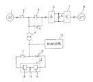
図1は本発明の実施の形態を説明する回路構成図である。図1において、1は商用交流電源、2はしゃ断器、3は平常時に閉路し停電時に開路する平常運転用接点、4は平常時には開路しており停電時に閉路する停電時用接点、5はコンバータ、6は平滑用コンデンサ、7はインバータ、8はエレベータ駆動用の誘導電動機、9は単相トランス、10はインバータ7の制御およびエレベータの種々の運転制御を行う制御回路、11は平常時には閉路しており停電時に開路する接点、12は平常時には開路しており停電時に閉路する接点、13は停電時のバックアップ電源であり、例えば整流器14,バッテリー15,インバータ16等からなる交流無停電電源装置(UPS)で構成される。
【0006】
以上の構成において、平常時には商用交流電源1から接点3を介してコンバータ5に交流電力が供給され、直流電力に変換される。インバータ7はこの直流電力を可変電圧・可変周波数の3相交流に変換して誘導電動機8に供給しエレベータを駆動する。
【0007】
また、商用交流電源1から単相トランス9を介して例えば交流の100Vに降圧され、制御回路10に供給されてインバータ7の制御やエレベータの種々の運転制御が行われるとともに、接点11及びバックアップ電源13内の整流器14を介してバッテリー15の充電が行われている。
【0008】
一方、停電時には接点3及び11が開路し接点4及び12が閉路することにより、バッテリー15からの直流電力がインバータ装置16を介して100Vの交流電力に変換され、制御回路10に直接供給されるとともに、単相トランス9を介して電源電圧と同じ電圧まで昇圧された交流電力がコンバータ5に供給され、誘導電動機を平常時と同様に駆動してエレベータの救出運転が行われる。
【0009】
なおこの場合、停電時にはコンバータ5へは単相の交流電力が供給されることになるが、一般的にエレベータの救出運転は短時間であるので特に支障は生じない。
【0010】
【発明の効果】
本発明によれば、停電時でも電源電圧と同じ電圧をインバータに供給できるのでエレベータを定格速度で運転することができ、バッテリー容量を必要最小限に留めることができる。また電源電圧に拘らず同一のバックアップ電源を追加するだけでよく、構成が簡単でしかも標準化が容易となる。
【図面の簡単な説明】
【図1】本発明におけるエレベータの制御装置の回路図である。
【符号の説明】
1 商用交流電源
5 コンバータ
6 平滑用コンデンサ
7 インバータ
8 誘導電動機
9 単相トランス
10 制御回路
13 バックアップ電源
15 バッテリー[0001]
TECHNICAL FIELD OF THE INVENTION
The present invention relates to an elevator control device that operates an elevator using an inverter device and performs a rescue operation via a backup power source via the inverter device when a power failure occurs.
[0002]
[Prior art]
If a power failure occurs during the operation of the elevator, the elevator may stop between floors and trap passengers. As a countermeasure against this, a power failure operation rescue device that supplies DC power to an inverter using a backup power supply at the time of power failure and operates the elevator to the nearest floor has been put to practical use.
A battery is generally used as the backup power supply for reasons such as economy, and the number of used batteries is kept to a minimum.
[0003]
[Problems to be solved by the invention]
For this reason, the input DC voltage to the inverter of the main circuit at the time of a power failure is lower than that at the time of the commercial power supply, and accordingly, the voltage applied to the induction motor that drives the elevator also becomes lower. The speed had to be limited to several tenths to one tenth. For this reason, the driving time at the time of rescue becomes longer by that much, and a large capacity battery is required. Also, in order to make the operating speed the same between the case where the power supply is 200V system and the case where the power supply is 400V system, the voltage of the battery must be changed. there were.
[0004]
[Means for Solving the Problems]
SUMMARY OF THE INVENTION The present invention has been made to solve the above-described problems, and is characterized by a simple configuration in which a primary side is connected to a commercial AC power supply, and a secondary side is connected to a control circuit for controlling an inverter or the like. A backup power supply equipped with a chargeable / dischargeable battery and an inverter device is connected in parallel with the control circuit on the secondary side of the phase transformer, and in the event of a power failure, AC power is directly supplied from the backup power supply to the control circuit. In addition, the backup power supply supplies single-phase AC power having the same voltage as the commercial AC power supply voltage to the inverter via the single-phase transformer.
[0005]
BEST MODE FOR CARRYING OUT THE INVENTION
Hereinafter, an embodiment of an elevator control device according to the present invention will be described with reference to the drawings.
FIG. 1 is a circuit diagram illustrating an embodiment of the present invention. In FIG. 1, reference numeral 1 denotes a commercial AC power supply, 2 denotes a circuit breaker, 3 denotes a normal operation contact which is normally closed and opens when a power failure occurs, 4 denotes a power failure contact which is normally opened and is closed during a power failure, and 5 denotes a converter. , 6 is a smoothing capacitor, 7 is an inverter, 8 is an induction motor for driving an elevator, 9 is a single-phase transformer, 10 is a control circuit for controlling the inverter 7 and various operation controls of the elevator, and 11 is normally closed. A contact that opens during a power failure, 12 is a contact that opens during normal times and closes during a power failure, and 13 is a backup power supply during a power failure, such as an AC uninterruptible power supply (eg, a
[0006]
In the above configuration, AC power is supplied to the converter 5 from the commercial AC power supply 1 through the
[0007]
Further, the voltage is stepped down from the commercial AC power supply 1 to, for example, 100 V AC through a single-phase transformer 9 and supplied to a
[0008]
On the other hand, at the time of a power failure, the
[0009]
In this case, single-phase AC power is supplied to converter 5 at the time of a power failure, but there is no particular problem because the rescue operation of the elevator is generally short.
[0010]
【The invention's effect】
According to the present invention, the same voltage as the power supply voltage can be supplied to the inverter even during a power outage, so that the elevator can be operated at the rated speed and the battery capacity can be kept to a minimum. Also, it is only necessary to add the same backup power supply irrespective of the power supply voltage, so that the configuration is simple and standardization is easy.
[Brief description of the drawings]
FIG. 1 is a circuit diagram of an elevator control device according to the present invention.
[Explanation of symbols]
DESCRIPTION OF SYMBOLS 1 Commercial AC power supply 5 Converter 6 Smoothing capacitor 7 Inverter 8 Induction motor 9 Single-
Claims (2)
前記単相トランスの二次側に、内部に充放電可能なバッテリーとインバータ装置とを備えたバックアップ電源を前記制御回路と並列に接続し、停電時には前記バックアップ電源から前記制御回路に交流電力を直接供給するとともに、前記バックアップ電源から前記単相トランスを介して前記商用交流電源電圧と同電圧の単相交流電力を上記インバータに供給する構成としたことを特徴とするエレベータの制御装置。A converter for converting commercial AC power to DC, an inverter for converting the converter output to AC of variable voltage and variable frequency, and a control circuit for connecting the commercial AC power to the primary side and controlling the inverter on the secondary side In an elevator control device including a connected single-phase transformer and an induction motor that is fed by the inverter and drives the elevator,
On the secondary side of the single-phase transformer, a backup power supply including a chargeable / dischargeable battery and an inverter device is connected in parallel with the control circuit. An elevator control device, wherein the controller is configured to supply single-phase AC power having the same voltage as the commercial AC power supply voltage from the backup power supply via the single-phase transformer to the inverter.
Priority Applications (1)
| Application Number | Priority Date | Filing Date | Title |
|---|---|---|---|
| JP24188397A JP3580097B2 (en) | 1997-08-22 | 1997-08-22 | Elevator control device |
Applications Claiming Priority (1)
| Application Number | Priority Date | Filing Date | Title |
|---|---|---|---|
| JP24188397A JP3580097B2 (en) | 1997-08-22 | 1997-08-22 | Elevator control device |
Publications (2)
| Publication Number | Publication Date |
|---|---|
| JPH1160101A JPH1160101A (en) | 1999-03-02 |
| JP3580097B2 true JP3580097B2 (en) | 2004-10-20 |
Family
ID=17080972
Family Applications (1)
| Application Number | Title | Priority Date | Filing Date |
|---|---|---|---|
| JP24188397A Expired - Lifetime JP3580097B2 (en) | 1997-08-22 | 1997-08-22 | Elevator control device |
Country Status (1)
| Country | Link |
|---|---|
| JP (1) | JP3580097B2 (en) |
Families Citing this family (6)
| Publication number | Priority date | Publication date | Assignee | Title |
|---|---|---|---|---|
| JP3059336B2 (en) * | 1994-04-06 | 2000-07-04 | 三菱電機株式会社 | Antenna device and mobile communication device |
| JP4233958B2 (en) | 2003-08-29 | 2009-03-04 | 株式会社日本自動車部品総合研究所 | Rotation angle detector |
| DE602005008773D1 (en) * | 2005-01-13 | 2008-09-18 | Otis Elevator Co | ACTUATING DEVICE FOR AN ELEVATOR SYSTEM |
| WO2014108599A1 (en) * | 2013-01-09 | 2014-07-17 | Kone Corporation | Electric power system |
| KR101877181B1 (en) * | 2017-09-20 | 2018-07-10 | 이용규 | Elevator operation apparatus including an emergency escape apparatus that transformers used both as control panel and escape apparatus and Control method thereof |
| JP6981445B2 (en) * | 2019-04-24 | 2021-12-15 | フジテック株式会社 | Passenger conveyor |
Family Cites Families (8)
| Publication number | Priority date | Publication date | Assignee | Title |
|---|---|---|---|---|
| JPS6043094A (en) * | 1983-08-17 | 1985-03-07 | Mitsubishi Electric Corp | Operating device of elevator when in trouble |
| JPS61210894A (en) * | 1985-03-13 | 1986-09-19 | Mitsubishi Electric Corp | Stop interruption rescue device of elevator |
| JPH0659983B2 (en) * | 1988-11-16 | 1994-08-10 | 株式会社日立製作所 | Elevator emergency operation system at power failure |
| JPH04244745A (en) * | 1991-01-28 | 1992-09-01 | Mitsubishi Electric Corp | Controller for ac elevator |
| JPH0632553A (en) * | 1992-07-16 | 1994-02-08 | Hitachi Ltd | Elevator device |
| JP3406361B2 (en) * | 1993-12-01 | 2003-05-12 | 三菱電機株式会社 | Elevator blackout operation device |
| JPH1017234A (en) * | 1996-07-04 | 1998-01-20 | Mitsubishi Electric Corp | Elevator driving device for use at power failure |
| KR100186370B1 (en) * | 1996-10-24 | 1999-04-15 | 이종수 | Emergency drive equipment of an elevator during power failure |
-
1997
- 1997-08-22 JP JP24188397A patent/JP3580097B2/en not_active Expired - Lifetime
Also Published As
| Publication number | Publication date |
|---|---|
| JPH1160101A (en) | 1999-03-02 |
Similar Documents
| Publication | Publication Date | Title |
|---|---|---|
| JPH0575669B2 (en) | ||
| JPH0231594B2 (en) | ||
| JP3250448B2 (en) | Inverter device | |
| JPH07238929A (en) | Magnetic bearing device | |
| JP3580097B2 (en) | Elevator control device | |
| CN111792483A (en) | Elevator with a movable elevator car | |
| JPH08169653A (en) | Energy-saving system for elevator | |
| KR102345574B1 (en) | Elevator ard included a power regenerative unit | |
| JP3406361B2 (en) | Elevator blackout operation device | |
| JPH036742B2 (en) | ||
| JPH07252040A (en) | Power converting device of elevator | |
| JP2005104608A (en) | Operation device of door motor for elevator at power failure | |
| JP2839638B2 (en) | Elevator control device | |
| JPS63186505A (en) | Controller for ac electric car | |
| JP2004189482A (en) | Elevator system | |
| JPS64314B2 (en) | ||
| JPH07293563A (en) | Drive control device for rotating device supporting rotor on magnetic bearing | |
| JP2004175548A (en) | Elevator system | |
| JP3748008B2 (en) | Power supply system | |
| JPH02147581A (en) | Controller for elevator | |
| JPH0475485A (en) | Power converting system | |
| JP3314789B2 (en) | Inverter drive | |
| JPH02136043A (en) | Uninterruptive power supply | |
| JP2001019311A (en) | Elevator control device | |
| JPH1179592A (en) | Elevator operation device in power failure |
Legal Events
| Date | Code | Title | Description |
|---|---|---|---|
| A977 | Report on retrieval |
Free format text: JAPANESE INTERMEDIATE CODE: A971007 Effective date: 20040316 |
|
| A131 | Notification of reasons for refusal |
Free format text: JAPANESE INTERMEDIATE CODE: A131 Effective date: 20040406 |
|
| A521 | Written amendment |
Free format text: JAPANESE INTERMEDIATE CODE: A523 Effective date: 20040604 |
|
| TRDD | Decision of grant or rejection written | ||
| A01 | Written decision to grant a patent or to grant a registration (utility model) |
Free format text: JAPANESE INTERMEDIATE CODE: A01 Effective date: 20040629 |
|
| A61 | First payment of annual fees (during grant procedure) |
Free format text: JAPANESE INTERMEDIATE CODE: A61 Effective date: 20040712 |
|
| R150 | Certificate of patent or registration of utility model |
Free format text: JAPANESE INTERMEDIATE CODE: R150 |
|
| S531 | Written request for registration of change of domicile |
Free format text: JAPANESE INTERMEDIATE CODE: R313531 |
|
| R350 | Written notification of registration of transfer |
Free format text: JAPANESE INTERMEDIATE CODE: R350 |
|
| FPAY | Renewal fee payment (event date is renewal date of database) |
Free format text: PAYMENT UNTIL: 20100730 Year of fee payment: 6 |
|
| FPAY | Renewal fee payment (event date is renewal date of database) |
Free format text: PAYMENT UNTIL: 20110730 Year of fee payment: 7 |
|
| FPAY | Renewal fee payment (event date is renewal date of database) |
Free format text: PAYMENT UNTIL: 20110730 Year of fee payment: 7 |
|
| FPAY | Renewal fee payment (event date is renewal date of database) |
Free format text: PAYMENT UNTIL: 20120730 Year of fee payment: 8 |
|
| FPAY | Renewal fee payment (event date is renewal date of database) |
Free format text: PAYMENT UNTIL: 20130730 Year of fee payment: 9 |
|
| R250 | Receipt of annual fees |
Free format text: JAPANESE INTERMEDIATE CODE: R250 |
|
| R250 | Receipt of annual fees |
Free format text: JAPANESE INTERMEDIATE CODE: R250 |
|
| R250 | Receipt of annual fees |
Free format text: JAPANESE INTERMEDIATE CODE: R250 |
|
| R250 | Receipt of annual fees |
Free format text: JAPANESE INTERMEDIATE CODE: R250 |
|
| EXPY | Cancellation because of completion of term |