JP3577288B2 - Power failure control method and power failure control device for rotary press - Google Patents
Power failure control method and power failure control device for rotary press Download PDFInfo
- Publication number
- JP3577288B2 JP3577288B2 JP2001109471A JP2001109471A JP3577288B2 JP 3577288 B2 JP3577288 B2 JP 3577288B2 JP 2001109471 A JP2001109471 A JP 2001109471A JP 2001109471 A JP2001109471 A JP 2001109471A JP 3577288 B2 JP3577288 B2 JP 3577288B2
- Authority
- JP
- Japan
- Prior art keywords
- unit
- power
- power failure
- power supply
- printing material
- Prior art date
- Legal status (The legal status is an assumption and is not a legal conclusion. Google has not performed a legal analysis and makes no representation as to the accuracy of the status listed.)
- Expired - Lifetime
Links
- 238000000034 method Methods 0.000 title claims description 8
- 230000007246 mechanism Effects 0.000 claims description 84
- 238000003825 pressing Methods 0.000 claims description 23
- 238000011144 upstream manufacturing Methods 0.000 claims description 12
- 238000000926 separation method Methods 0.000 claims 1
- 230000005540 biological transmission Effects 0.000 description 9
- 238000010586 diagram Methods 0.000 description 6
- 238000001514 detection method Methods 0.000 description 5
- 230000001360 synchronised effect Effects 0.000 description 3
- 230000001788 irregular Effects 0.000 description 2
- 238000004804 winding Methods 0.000 description 2
- 230000009471 action Effects 0.000 description 1
- 230000007423 decrease Effects 0.000 description 1
- 238000006073 displacement reaction Methods 0.000 description 1
- 230000000694 effects Effects 0.000 description 1
- 230000007274 generation of a signal involved in cell-cell signaling Effects 0.000 description 1
- 230000009467 reduction Effects 0.000 description 1
- 230000004044 response Effects 0.000 description 1
Images


Classifications
-
- B—PERFORMING OPERATIONS; TRANSPORTING
- B41—PRINTING; LINING MACHINES; TYPEWRITERS; STAMPS
- B41F—PRINTING MACHINES OR PRESSES
- B41F33/00—Indicating, counting, warning, control or safety devices
- B41F33/04—Tripping devices or stop-motions
- B41F33/12—Tripping devices or stop-motions for starting or stopping the machine as a whole
-
- B—PERFORMING OPERATIONS; TRANSPORTING
- B41—PRINTING; LINING MACHINES; TYPEWRITERS; STAMPS
- B41F—PRINTING MACHINES OR PRESSES
- B41F13/00—Common details of rotary presses or machines
- B41F13/004—Electric or hydraulic features of drives
- B41F13/0045—Electric driving devices
-
- B—PERFORMING OPERATIONS; TRANSPORTING
- B41—PRINTING; LINING MACHINES; TYPEWRITERS; STAMPS
- B41P—INDEXING SCHEME RELATING TO PRINTING, LINING MACHINES, TYPEWRITERS, AND TO STAMPS
- B41P2213/00—Arrangements for actuating or driving printing presses; Auxiliary devices or processes
- B41P2213/70—Driving devices associated with particular installations or situations
- B41P2213/73—Driving devices for multicolour presses
- B41P2213/734—Driving devices for multicolour presses each printing unit being driven by its own electric motor, i.e. electric shaft
Landscapes
- Engineering & Computer Science (AREA)
- Mechanical Engineering (AREA)
- Inking, Control Or Cleaning Of Printing Machines (AREA)
- Rotary Presses (AREA)
Description
【0001】
【発明の属する技術分野】
この発明は、輪転機の制御方法及び制御装置に係り、特に、それぞれ別個の駆動源によって印刷部と折部とを駆動して印刷稼動する所謂シャフトレス輪転機の、停電時の制御方法及び制御装置に関する。
【0002】
【従来の技術】
従来の輪転機は、例えば特公昭60−36946号公報に開示されるように、輪転機を構成する印刷部、折部などに設けられた複数の駆動源(主電動機)を、駆動伝動軸(主軸)とクラッチとを介して連結し、一体化した駆動源によって輪転機全体を駆動し、印刷稼動させるものであった。
【0003】
これに対し、昨今、例えば特許第3037650号公報や特許第3059081号公報に開示されるような、複数の駆動源がそれぞれ異なる被駆動部を個別に駆動するようにし、各駆動源や被駆動部の回転速度と回転位相とが夫々適切に整合するよう電気的に同期制御するようにした、所謂シャフトレス輪転機が、印刷稼動における様々な利点を有することから、一気に普及しはじめている。
【0004】
【発明が解決しようとする課題】
しかしながら、前記昨今一気に普及しはじめた所謂シャフトレス輪転機では、印刷稼動中に電気的な同期制御が不能になった場合、例えば停電などの電源ダウンが発生して給電が遮断された場合、各駆動源と被駆動部とがその慣性力で回転するようになり、良好な印刷が行われないのは勿論のこと、輪転機内を走行する連続紙に統一性のない張力が作用して連続紙の破断が生じ、破断した連続紙が回転部に巻き付くなどのトラブルが生じることがあった。そして、この巻き付いた連続紙の除去や走行コースへの連続紙の通し直しなど印刷稼動可能状態への復旧に多くの時間を必要とし、電源が回復しても即座に印刷稼動を再開することができず、これは、例えば新聞印刷などの迅速かつタイムリーな印刷を要する印刷では、解決を必要とする極めて重大な課題となっていた。
【0005】
他方、この課題の解決策として、前記特許第3037650号公報に開示されたシャフトレス輪転機では、電源トラブルなどで給電が遮断されたときに被駆動部分を個別に制動して輪転機を停止するようにしている。しかし、この輪転機の制御では、給電が遮断された後に各被駆動部が回転を続けようとする慣性力に差があり、またこの慣性力による回転を制動しようとする制動力にも少なからぬ差があり、更に、各制動部における制動開始のタイミングに若干のずれが生じるため、各被駆動部の制動作用による回転速度低下開始のタイミングや停止に至るまでの時間にばらつきが生じてしまい、やはり、輪転機内を走行する連続紙に統一性のない張力が作用し、連続紙が破断し、破断した連続紙が回転部に巻き付くのを回避できなかった。
【0006】
この発明は、電気的に同期制御されるシャフトレス輪転機において、電源トラブルなどで給電が遮断されたときでも、輪転機内を走行する連続紙に統一性のない張力が作用しないようにし、連続紙が破断して破断した連続紙が回転部に巻き付くことを防止し、電源が回復した後即座に印刷稼動を再開することができるようにすることを目的とするものである。
【0007】
【課題を解決するための手段】
この発明は、特許請求の範囲に記載した構成によって前記目的を達成しようとするものである。
【0008】
即ち、第1の発明は、それぞれ別個の駆動源によって印刷部と折部とを駆動し、かつ給紙部で制動している被印刷材を少なくとも折部で牽引するとともに、印刷部のブランケット胴を被印刷材に接触させて印刷稼動する輪転機の制御方法において、
停電による給電停止により、給紙部での被印刷材の制動を一定の制動力によって行うように切り替え、
停電時の電圧降下を検出して停電信号を出力するとともに、電源を蓄電電源に切替え、
停電信号と蓄電電源からの電力とにより、印刷稼動中のブランケット胴を被印刷材から離隔し、
かつ、停電信号と蓄電電源からの電力とにより、折部での被印刷材の牽引機構を予め定めた所定時間内に減速を経て停止する
ようにする。
【0009】
また第2の発明は、それぞれ別個の駆動源によって印刷部と折部とを駆動し、かつ給紙部で制動している被印刷材を少なくとも折部で牽引するとともに、印刷部のブランケット胴を被印刷材に接触させて印刷稼動する輪転機の制御において、
停電による給電停止により、給紙部での被印刷材の制動を停電前の制動力よりも強い一定の制動力によって行うように切り替え、
停電時の電圧降下を検出して停電信号を出力するとともに、電源を蓄電電源に切替え、
停電信号と蓄電電源からの電力とにより、印刷稼動中のブランケット胴を被印刷材から離隔し、
かつ、停電信号と蓄電電源からの電力とにより、折部での被印刷材の牽引機構を予め定めた所定時間内に減速を経て停止する
ようにする。
【0010】
更に第3の発明は、それぞれ別個の駆動源を印刷部と折部とに有し、被印刷材引き出しに対する被印刷材制動機構を給紙部に有し、ブランケット胴を被印刷材に対して接触方向と離隔方向に選択的に移動させるブランケット胴移動機構を印刷部に有し、ドラッグローラーの回転によって被印刷材を牽引する被印刷材牽引機構を少なくとも折部の最上流に有する輪転機において、
停電による給電停止により、制動力が一定である停電時制動力に切り替え可能に設けた被印刷材制動機構と、
電力入力側が外部電源に連結され、停電時の電力入力側の電圧降下を検出して停電信号を出力する停電信号出力部、及び停電時の電力入力側の電圧降下にともなって電力出力側に電力出力する蓄電電源部を有する無停電電源部と、
各駆動源の回転基準を示す基準パルス信号を出力する回転制御信号出力部と、
回転制御信号出力部の出力する基準パルス信号が示す回転基準に基づいて印刷部と折部の駆動源の回転速度を補正するべく各駆動源ごとに設けられた駆動源制御部と、
ブランケット胴を選択的に被印刷材に対し接触又は離隔させるべくブランケット胴移動機構を動作させる移動機構制御部と、
を有し、
更に、回転制御信号出力部並びに前記制御部のうち少なくとも折部最上流の被印刷材牽引機構のドラッグローラーの駆動源制御部及び移動機構制御部が、無停電電源部の電力出力側に連結されるとともに、無停電電源部の電力出力側に連結されない制御部が外部電源と直接連結され、
少なくとも回転制御信号出力部及び移動機構制御部が、無停電電源部の停電信号出力部に連結されて設けられ、
停電にともなって少なくとも折部最上流の被印刷材牽引機構のドラッグローラーの駆動源制御部、回転制御信号出力部及び移動機構制御部が動作し、停電信号出力部の信号に基づいてブランケット胴を被印刷材から離隔させるとともに、折部最上流の被印刷材牽引機構を、回転制御信号出力部が出力する基準パルス信号が示す回転基準に基づいて予め定めた所定時間で減速させ停止させるように設けられる。
【0011】
この発明の構成によれば、外部電源の停電などの電源トラブルが発生した場合以下のとおりの作用が行われる。
【0012】
まず、外部電源の停電などの電源トラブルによって無停電電源部の電力入力側の電圧が降下すると、無停電電源部は、停電信号出力部が停電信号を出力するとともに、蓄電電源部から電力出力側に電力を出力する。また、給紙部の被印刷材制動機構は、外部電源の停電などの電源トラブルによって給電が停止すると、制動力が一定であるように切り替えられる。
【0013】
出力された停電信号は、少なくとも回転制御信号出力部及び移動機構制御部に入力される。また、蓄電電源部から電力出力側に出力された電力は、少なくとも折部最上流の被印刷材牽引機構のドラッグローラーの駆動源制御部、回転制御信号出力部及び移動機構制御部に入力される。
【0014】
回転制御信号出力部及び移動機構制御部は、停電信号の入力により輪転機停止モードに切り替えられ、蓄電電源部からの電力によって輪転機停止モードの作動を行う。また、ドラッグローラー駆動源制御部は、蓄電電源部からの電力によって回転制御信号出力部が出力する輪転機停止モードの信号に従って駆動源制御作動を続ける。すなわち、回転制御信号出力部は、輪転機内を走行する被印刷材を、減速を経て予め定められた時間内に停止させるべく、折部最上流の被印刷材牽引機構のドラッグローラーを次第に減速させて停止させる制御信号を出力する。この制御信号を受けて、ドラッグローラー駆動源制御部は、折部最上流の被印刷材牽引機構のドラッグローラーの回転駆動を減速し終には停止させる。なお、減速から停止に至る時間は、蓄電電源部からの給電が可能な時間内に定められる。
【0015】
移動機構制御部は、停電信号を受けると即座にブランケット胴移動機構を動作させ、それまで被印刷材に接触する印刷位置に位置していたブランケット胴を被刷材から離隔した非印刷位置に移動させる。
【0016】
この間、制動力が一定であるように切り替えられた給紙部の被印刷材制動機構は、被印刷材が折部最上流の被印刷材牽引機構のドラッグローラーの回転によって引き出されるのを、一定の制動力で制動し続ける。
【0017】
以上記載のとおり、回転制御信号出力部、ドラッグローラー駆動源制御部、移動機構制御部及び被印刷材制動機構が作動し、輪転機内を走行する被印刷材は、一定の制動力下で電気的制御によって減速され停止される。
【0018】
【発明の実施の形態】
次に、この発明の一つの実施の形態を、図面を参照しながら説明する。
【0019】
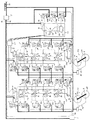
図1は、オフセット輪転機に、本発明に係る停電時制御装置の1つの実施の形態を適用したものを示す説明図である。図1においてはそれぞれ4つの印刷機構Pを有する印刷部CT1、CT2、印刷された連続紙Wを所定の印刷画像ごとに切断して折り畳む折部FD及び印刷部CT1、CT2ごとに設けられ対応する印刷部CT1又はCT2に被印刷材である連続紙Wを供給する給紙部SP1、SP2を備えたオフセット輪転機が示されている。
【0020】
各印刷部CT1、CT2の印刷機構Pは、ブランケット胴BCと版胴PCとの印刷カップルが2組ずつ設けられている。
【0021】
各印刷カップルは、版胴PCが伝動手段GTを介して、駆動手段Mによって駆動される。またブランケット胴BCは、版胴PC、及び版胴PCとブランケット胴BCとの両胴間に設けられた図示しない伝動手段を介して、駆動手段Mによって駆動される。すなわち、各印刷部CT1、CT2の印刷機構Pは、それぞれ独立した駆動手段Mで駆動されるようになっている。各印刷部CT1、CT2の上流近傍には、連続紙Wを対応する印刷部CT1又はCT2に送り込むインフィードローラーINが設けられており、また各印刷部CT1、CT2の下流近傍には、連続紙Wを対応する印刷部CT1又はCT2から引き出すアウトフィードローラーOTが設けられており、これらのローラーはいずれも、伝動手段GTを介して駆動手段Mによって駆動される。インフィードローラーINの上流には、例えばダンサーローラーを用いた張力検出機構である第1張力検出手段DNが、アウトフィードローラーOTの上流には、例えば歪みゲージを用いた張力検出機構である第2張力検出手段TPが設けられている。
【0022】
また、折部FDは、折胴FCが伝動手段GTを介して、また他の胴は折胴FCと他の胴との間に設けられた図示しない伝動手段を介して、駆動手段Mによって駆動される。折胴FCの上流近傍には、連続紙Wを折胴FCと他の胴とが近接する隙間に送り込むニッピングローラーNIが設けられており、また折部FDの最上流には、連続紙Wを折部FDに送り込むドラッグローラーDRが設けられており、これらのローラーはいずれも、伝動手段GTを介して駆動手段Mによって駆動される。
【0023】
なお、上記いずれの胴及びローラーにおいても、伝動手段GTをなくして駆動手段Mで直接駆動するようにしてもよい。
【0024】
前記駆動手段Mには、各駆動手段Mに応する駆動源制御部3である、(i)#11〜#18と#21〜#28との印刷カップル駆動源制御部30、(ii)#10と#20とのインフィードローラー駆動源制御部31、(iii) #19と#29とのアウトフィードローラー駆動源制御部32、(iv)#97のドラッグローラー駆動源制御部33、(v)#98のニッピングローラー駆動源制御部34、(vi)#99の折胴駆動源制御部35が設けられている。また更に駆動手段Mの回転の角変位量に比例する数だけの、第1パルス信号を出力するとともに、1回転ごとに第2パルス信号(Z相パルス信号)を出力するフィードバック信号出力部であるZ相付きロータリーエンコーダー(インクリメンタルエンコーダー;以下、エンコーダーとする)ENが設けられている。駆動源制御部3は、図5で説明する入力側インターフェース36、連結ケーブル92を介して回転制御信号出力部2に接続されている。
【0025】
さらに、印刷部CT1、CT2の各印刷カップルには、それぞれのブランケット胴BCのブランケット面を連続紙Wに対して接触させ又は離隔させるべく、選択的にブランケット胴BCを移動させる、例えばエアーシリンダーを駆動源としたブランケット胴移動機構である所のブランケット胴切替機構6が設けられ、各ブランケット胴切替機構6・・は、各印刷部CT1又はCT2のブランケット胴切替機構6・・の動作を制御する移動機構制御部60に、連結配管93を介して連結されている。また、前記折部FDの最上流に設けられた連続紙Wを折部FDに送り込むドラッグローラーDRには、このドラッグローラーDRに連続紙Wを押し付けながら回転可能な回転部材PRがドラッグローラーDRの軸方向に離隔した適宜の複数個所に設けられ、各回転部材PR・・は、回転部材押付け機構7に連結され、さらに回転部材押付け機構7は、回転部材PR・・による連続紙WをドラッグローラーDRに押し付ける押付け力を切り替える押付け力制御部70に、連結配管94を介して連結されている。
【0026】
給紙部SP1,SP2には、それぞれ連続紙Wの巻取体WRの支持機構(図示せず)が複数設けられるとともに、各支持機構ごとに、例えばエアー作動ブレーキを有する被印刷材制動機構8・・が設けられ、各被印刷材制動機構8・・は、連続紙Wへの制動力切換えをする被印刷材制動制御部80に、連結配管95を介して連結されている。
【0027】
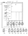
他方、図示しない外部電源と連結されて無停電電源部1が設けられている。図2に示す如く、無停電電源部1には、電力入力側にコンバーター部11、電力出力側にインバーター部13が設けられるとともに、蓄電電源部12及び停電信号出力部14が設けられており、当該無停電電源部1は、外部電源から給電された交流電力をコンバーター部11で一旦直流電力に変換して蓄電電源部12に蓄えるとともに、変換した直流電力をインバーター部13で交流電力に戻して電力出力するように構成されている。また、停電信号出力部14は、外部電源が停電するなどしてコンバーター部11へ給電される電力の電圧が低下すると、これを検知して停電信号を出力する。出力された停電信号は、連結ケーブル96を介して回転制御信号出力部2、移動機構制御部60、押付け力制御部70に入力される。
【0028】
無停電電源部1の電力出力側には、前記ドラッグローラー駆動源制御部33、移動機構制御部60及び押付け力制御部70が、連結ケーブル91を介して連結されている。また、印刷カップル駆動源制御部30、インフィードローラー駆動源制御部31、アウトフィードローラー駆動源制御部32、ニッピングローラー駆動源制御部34、折胴駆動源制御部35及び被印刷材制動制御部80は、連結ケーブル90を介して図示しない外部電源と連結されている。
【0029】
なお、図1の中央上部に示す符号ADは、連続紙Wを幅方向の中央で長手方向と平行に切断し、かつ折部での切断単位となる画像位置が長手方向で一致した状態で重ね合わせる重ね合せ機構であるが、本発明に関係しないので詳細な説明を省略する。
【0030】
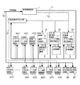
次に、以上記載の構成による作動について説明するとともに、図1に示す停電時制御装置をブロック図で示した図2乃至図5を参照してその構成を若干詳細に説明する。
【0031】
輪転機は、外部電源にトラブルが無いときは通常のように稼動する。すなわち、外部電源がONされると、無停電電源部1、印刷カップル駆動源制御部30、インフィードローラー駆動源制御部31、アウトフィードローラー駆動源制御部32、ニッピングローラー駆動源制御部34、折胴駆動源制御部35及び被印刷材制動制御部80に、連結ケーブル90を介して電力供給される。電力供給された無停電電源部1では、入力された電力がコンバーター部11で交流から直流に変換され、さらにインバーター部13で交流から直流に変換されて出力され、回転制御信号出力部2、ドラッグローラー駆動源制御部33、移動機構制御部60及び押付け力制御部70に給電される。また、無停電電源部1では、交流から直流に変換された電力が蓄電電源部12に蓄えられる。
【0032】
このような状態になった後、回転制御信号出力部2(図3参照)の入力操作部21から、例えば起動、次に増速といった輪転機の稼動操作信号を入力し、輪転機を作動させる。稼動操作信号を入力された回転制御信号出力部2は、処理部22で入力された稼動操作信号に見合う制御信号、例えば回転基準を示す基準パルス信号を出力させるべく制御信号発生部23に信号出力指令する。処理部22から信号出力指令された制御信号発生部23は、指令にしたがって制御信号を出力し、この信号は、出力側インターフェース24を介して連結ケーブル92に出力される。
【0033】
連結ケーブル92に出力された回転制御信号出力部2が出力した信号は、図5に示す如く、入力側インターフェース36を介して各駆動源制御部3・・に入力される。回転制御信号出力部2が出力した信号を入力された駆動源制御部3は、この信号を処理部37で処理して基準位相と基準速度を抽出するとともに、エンコーダーENが出力する第1パルス信号及び第2パルス信号から対応する駆動手段Mの当該時点における位相と速度とを抽出し、さらに抽出した基準位相と駆動手段Mの当該時点における位相とを比較し、かつ基準速度と駆動手段Mの当該時点における速度とを比較し、速度差及び位相差をなくすべく基準速度を補正した補正信号を出力し、増幅器38を介して補正信号に見合った適宜の駆動電力を駆動手段Mに供給する。なお、駆動源制御部3のうち、インフィードローラー駆動源制御部31は前記基準速度を補正する際に第1張力検出手段DNの出力信号をも取り込んで補正し、アウトフィードローラー駆動源制御部32は前記基準速度を補正する際に第2張力検出手段TPの出力信号をも取り込んで補正している。
【0034】
このようにして、輪転機の各駆動回転部は同期回転駆動される。
この同期回転駆動される間、移動機構制御部60(図4参照)は、予め定められた輪転機起動後の適宜のタイミングでブランケット胴移動切替電磁弁61を切り替え、ブランケット胴切替機構6を動作させて、同期回転駆動によって走行する連続紙Wにブランケット胴BCのブランケット面を接触させ、この状態を維持する。押付け力制御部70(図4参照)は、輪転機起動とともに電空変換器71で予め設定された空圧を回転部材押付け機構7に供給して回転部材PRをドラッグローラーDRに押付け、ドラッグローラーDRに接触して案内される連続紙Wを回転部材PRによってドラッグローラーDRに押し付ける。また、被印刷材制動制御部80は、当該印刷稼動時点の連続紙Wの巻取体WRの径に応じて被印刷材制動電磁弁81を切り替え、当該印刷稼動時点の連続紙Wの巻取体WRの径に見合った制動を行うべく被印刷材制動機構8を作動させるとともに、公知の給紙張力検出手段(図示せず)の検出する給紙張力に応じて、被印刷材制動機構8に供給する空圧を常時調整させる。なお、当該印刷稼動時点の連続紙Wの巻取体WRの径は適宜公知の検出手段(図示せず)で検出すればよい。
【0035】
以上記載の状態で輪転機が通常稼動しているときに、外部電源に停電が生じると、図1に示す停電時制御装置は、次のように制御作動する。
【0036】
すなわち、図2を参照すると判る如く、無停電電源部1は、コンバーター部11に入力される電力の電圧が低下したのを停電信号出力部14が検出して停電信号を出力するとともに、蓄電電源部12から直流電力が出力され、この直流電力をインバーター部13で交流電力に変換して出力する。無停電電源部1が出力した停電信号は、連結ケーブル96を介して回転制御信号出力部2、移動機構制御部60及び押付け力制御部70に入力され、無停電電源部1が出力した蓄電電源部12からの直流電力に基づく交流電力は、連結ケーブル91を介して回転制御信号出力部2、ドラッグローラー駆動源制御部33、移動機構制御部60及び押付け力制御部70に入力される。
【0037】
他方、連結ケーブル90を介して外部電源と直接連結された印刷カップル駆動源制御部30、インフィードローラー駆動源制御部31、アウトフィードローラー駆動源制御部32、ニッピングローラー駆動源制御部34、折胴駆動源制御部35及び被印刷材制動制御部80は、電力の供給が停止される。
【0038】
すると、停電信号と無停電電源部1が出力した蓄電電源部12からの直流電力に基づく交流電力とを共に入力されている回転制御信号出力部2は、駆動回転されている部分を、予め定めた所定時間、例えば15秒で減速し停止させるよう、当該駆動手段Mを回転させる回転基準を示す信号を出力する。そして、無停電電源部1が出力した蓄電電源部12からの直流電力に基づく交流電力を入力されたドラッグローラー駆動源制御部33は、ドラッグローラーDRを、無停電電源部1が出力する前記駆動手段Mを減速停止させるよう回転させる回転基準を示す信号に従って回転制御する。加えて、停電信号と無停電電源部1が出力した蓄電電源部12からの直流電力に基づく交流電力とを共に入力された押付け力制御部70は、電空変換器71で予め設定された空圧を維持し又は電空変換器71で予め設定された空圧をより強い値に変更し、回転部材押付け機構7に供給して回転部材PRをドラッグローラーDRに押付け、ドラッグローラーDRに接触して案内される連続紙Wを回転部材PRによってドラッグローラーDRに押し付ける状態を維持する。したがって、ドラッグローラーDRは、外部電源に停電トラブルが生じた後も、連続紙Wを制御回転のもとで減速しながら牽引し、終には停止する。
【0039】
また、停電信号と無停電電源部1が出力した蓄電電源部12からの直流電力に基づく交流電力とを共に入力された移動機構制御部60は、図4から判る如く、即座にブランケット胴移動切替電磁弁61を切り替え、ブランケット胴切替機構6を動作させて、連続紙Wからブランケット胴BCのブランケット面を離隔させ、この状態を維持する。
【0040】
他方、電力の供給が停止された印刷カップル駆動源制御部30、インフィードローラー駆動源制御部31、アウトフィードローラー駆動源制御部32、ニッピングローラー駆動源制御部34、折胴駆動源制御部35は、制御作動を停止する。したがって、印刷カップルを構成する版胴PCとブランケット胴BC、インフィードローラーIN、アウトフィードローラーOTはそれぞれ駆動手段Mによる制御回転から慣性力による回転に切り替わる。しかし、前記したようにブランケット胴BCのブランケット面が連続紙Wから離隔させられており、連続紙Wに印刷カップルの回転による大きなかつ不規則な張力が作用することが無い。
【0041】
また、電力の供給が停止された被印刷材制動制御部80は、被印刷材制動電磁弁81が内蔵されたスプリングによって切り替えられ、連続紙Wの巻取体WRの径に無関係にまた給紙張力に無関係に、被印刷材制動機構8が制動機能を最大限に発揮する状態に切り替えられる。
【0042】
以上記載のとおり、外部電源に停電トラブルが生じると輪転機は、ブランケット胴BCが離隔した連続紙Wは、給紙部SP1、SP2の被印刷材制動機構8が最大制動機能を発揮した状態のもとで、ドラッグローラーDRの制御回転によって牽引され、予め定められた所定時間内に停止させられる。また、停止するまでの間に不規則かつ大きな張力が作用しないので、連続紙Wが切断することもない。
【0043】
なお、停電信号と無停電電源部1が出力した蓄電電源部12からの直流電力に基づく交流電力を、ドラッグローラー駆動源制御部33に加え、インフィードローラー駆動源制御部31、アウトフィードローラー駆動源制御部32、ニッピングローラー駆動源制御部34、折胴駆動源制御部35にも入力し、これらに対応する駆動手段Mを、前記ドラッグローラー駆動源制御部33によるドラッグローラーDRの駆動手段Mの制御と同様の制御を行わせるようにしてもよいことは勿論である。更にまた、印刷カップル駆動源制御部3と印刷カップルを駆動する駆動手段Mについても同様の作動を行わせるようにしてもよい。
【0044】
【発明の効果】
以上記載のとおりであり、この発明の実施により、電気的に同期制御されるシャフトレス輪転機において、電源トラブルなどで給電が遮断されたときでも、輪転機内を走行する連続紙に統一性のない張力が作用して連続紙が破断することを無くすことができた。したがって破断した連続紙が回転部に巻き付くことがなくなり、電源が回復した後即座に印刷稼動を再開することができるようになり、新聞印刷のような迅速タイムリーな印刷に大きな支障をきたすことが無くなった。また、輪転機の作動率向上にも極めて有効である。
【図面の簡単な説明】
【図1】オフセット輪転機に、本発明に係る停電時制御装置の1つの実施の形態を適用したものを示す説明図である。
【図2】図1に示す停電時制御装置の構成を示し無停電電源部の構成を若干詳細に示すブロック図である。
【図3】図1に示す停電時制御装置の構成を示し回転制御信号出力部の構成を若干詳細に示すブロック図である。
【図4】図1に示す停電時制御装置の構成を示し移動機構制御部及び押付け力制御部の構成を若干詳細に示すブロック図である。
【図5】図1に示す停電時制御装置の構成を示し駆動源制御部及び被印刷材制動制御部の構成を若干詳細に示すブロック図である。
【符号の説明】
1:無停電電源部
2:回転制御信号出力部
3:駆動源制御部
6:ブランケット胴切替機構
7:回転部材押付け機構
8:被印刷材制動機構
11:コンバーター部
12:蓄電電源部
13:インバーター部
14:停電信号出力部
21:入力操作部
22:処理部
23:制御信号発生部
24:出力側インターフェース
30:印刷カップル駆動源制御部
31:インフィードローラー駆動源制御部
32:アウトフィードローラー駆動源制御部
33:ドラッグローラー駆動源制御部
34:ニッピングローラー駆動源制御部
35:折胴駆動源制御部
36:入力側インターフェース
37:処理部
38:増幅器
60:移動機構制御部
61:ブランケット胴移動切替電磁弁
70:押付け力制御部
71:電空変換器
80:被印刷材制動制御部
81:被印刷材制動電磁弁
90:連結ケーブル
91:連結ケーブル
92:連結ケーブル
93:連結配管
94:連結配管
95:連結配管
96:連結ケーブル
AD:重ね合せ機構
BC:ブランケット胴
CT1、CT2:印刷部
DR:ドラッグローラ−
DN:第1張力検出手段
EN:エンコーダー
FC:折胴
FD:折部
GT:伝動手段
IN:インフィードローラー
M:駆動手段
NI:ニッピングローラー
OT:アウトフィードローラー
P:印刷機構
PC:版胴
PR:回転部材
SP1、SP2:給紙部
TP:第2張力検出手段
W:連続紙
WR:連続紙の巻取体[0001]
TECHNICAL FIELD OF THE INVENTION
The present invention relates to a control method and a control device for a rotary press, and more particularly to a control method and control for a so-called shaftless rotary press that performs printing by driving a printing unit and a folding unit by separate driving sources, respectively, at the time of a power failure. Equipment related.
[0002]
[Prior art]
2. Description of the Related Art As disclosed in, for example, Japanese Patent Publication No. 60-36946, a conventional rotary press includes a plurality of drive sources (main motors) provided in a printing unit, a folding unit, and the like, which constitute the rotary press, and a drive transmission shaft ( The rotary press is driven by an integrated drive source, and the printing operation is performed.
[0003]
On the other hand, recently, as disclosed in, for example, Japanese Patent No. 3037650 and Japanese Patent No. 3059081, a plurality of driving sources individually drive different driven parts, and each driving source and driven part are individually driven. The so-called shaftless rotary press, which is electrically controlled synchronously so that the rotational speed and the rotational phase of the rotary press appropriately match each other, has various advantages in the printing operation, and thus has begun to spread at a stretch.
[0004]
[Problems to be solved by the invention]
However, in the so-called shaftless rotary press that has begun to spread at a stretch in recent years, when the electric synchronous control becomes impossible during the printing operation, for example, when the power supply such as a power failure occurs and the power supply is cut off, The drive source and the driven part rotate by the inertial force, so that not only good printing is not performed, but also continuous paper running in the rotary press is subjected to inconsistent tension and continuous paper is applied. In some cases, such as breakage of the continuous paper wound around the rotating part. It takes a lot of time to restore the printable state, such as removing the wrapped continuous paper and re-passing the continuous paper on the running course, and it is possible to resume printing immediately after the power is restored. This has been a very serious problem that needs to be solved for printing that requires quick and timely printing, such as newspaper printing.
[0005]
On the other hand, as a solution to this problem, in a shaftless rotary press disclosed in Japanese Patent No. 3037650, when power supply is interrupted due to a power failure or the like, the driven portions are individually braked to stop the rotary press. Like that. However, in the control of this rotary press, there is a difference in the inertial force of each of the driven parts to keep rotating after the power supply is cut off, and the braking force for braking the rotation by the inertial force is not small. There is a difference, and furthermore, since a slight shift occurs in the timing of the braking start in each braking unit, a variation occurs in the timing of the start of rotation speed reduction due to the braking action of each driven unit and the time until reaching the stop, After all, tension that is not uniform acts on the continuous paper running in the rotary press, and the continuous paper breaks, and it cannot be avoided that the broken continuous paper winds around the rotating part.
[0006]
The present invention relates to a shaftless rotary press that is electrically controlled synchronously so that even if power supply is interrupted due to a power failure or the like, unconsistent tension acts on continuous paper running in the rotary press, and the continuous paper It is an object of the present invention to prevent the continuous paper that has been broken and wrapped around the rotating part from being wound, and to be able to immediately resume the printing operation after the power is restored.
[0007]
[Means for Solving the Problems]
The present invention aims to achieve the above object by the configuration described in the claims.
[0008]
That is, the first invention drives the printing unit and the folding unit by separate drive sources, respectively, and pulls the printing material braked by the paper feeding unit by at least the folding unit, and further comprises a blanket cylinder of the printing unit. In a method for controlling a rotary press that performs printing operation by contacting a printing medium with a printing material,
By stopping power supply due to a power outage, switching to perform braking of the printing material in the paper feeding unit with a constant braking force,
Detects a voltage drop during a power failure and outputs a power failure signal, and switches the power supply to a storage power supply.
The power failure signal and the power from the storage power supply separate the blanket cylinder during printing from the printing material,
In addition, due to the power failure signal and the electric power from the power storage power supply, the traction mechanism of the printing material at the folding part is decelerated within a predetermined time. Through Stop
To do.
[0009]
According to a second aspect of the present invention, the printing unit and the folding unit are driven by separate driving sources, and the printing material braked by the paper feeding unit is pulled at least by the folding unit, and the blanket cylinder of the printing unit is moved. In the control of a rotary press that performs printing by contacting the printing material,
By stopping the power supply due to the power failure, the printing material is switched in the paper feed unit so that the braking is performed by a constant braking force stronger than the braking force before the power failure,
Detects a voltage drop during a power failure and outputs a power failure signal, and switches the power supply to a storage power supply.
The power failure signal and the power from the storage power supply separate the blanket cylinder during printing from the printing material,
In addition, the traction mechanism of the printing material at the folding section is stopped after a deceleration within a predetermined time by the power failure signal and the power from the power storage power supply.
To do.
[0010]
Further, the third invention has a printing unit and a folding unit, each having a separate driving source, a printing material braking mechanism for a printing material drawer in a paper feeding unit, and a blanket cylinder for a printing material. In a rotary press having a blanket cylinder moving mechanism for selectively moving in a contact direction and a separating direction in a printing unit, and a printing material pulling mechanism for pulling a printing material by rotation of a drag roller at least at the uppermost stream of the folding unit. ,
A printing material braking mechanism provided to be switchable to a power failure braking force in which the braking force is constant by stopping power supply due to a power failure,
The power input side is connected to an external power supply, a power failure signal output unit that detects a voltage drop on the power input side during a power failure and outputs a power failure signal, and power is output to the power output side with a voltage drop on the power input side during a power failure. An uninterruptible power supply unit having a storage power supply unit for outputting,
A rotation control signal output unit that outputs a reference pulse signal indicating a rotation reference of each drive source,
A drive source control unit provided for each drive source to correct the rotation speed of the drive unit for the printing unit and the folding unit based on the rotation reference indicated by the reference pulse signal output from the rotation control signal output unit;
A moving mechanism control unit that operates a blanket cylinder moving mechanism to selectively contact or separate the blanket cylinder with respect to the material to be printed;
Has,
Further, a rotation control signal output unit and a drive source control unit and a movement mechanism control unit of a drag roller of the printing material pulling mechanism at the most upstream of the folding part among the control units are connected to a power output side of the uninterruptible power supply unit. In addition, the control unit not connected to the power output side of the uninterruptible power supply unit is directly connected to the external power supply,
At least a rotation control signal output unit and a movement mechanism control unit are provided in connection with the power failure signal output unit of the uninterruptible power supply unit,
With the power failure, the drive source control unit, the rotation control signal output unit, and the movement mechanism control unit of the drag roller of the printing material pulling mechanism at the most upstream of the folded part operate, and the blanket cylinder is operated based on the signal of the power failure signal output unit. A printing material pulling mechanism that is separated from the printing material and is the most upstream in the folded part. The times Based on the rotation reference indicated by the reference pulse signal output from the rotation control signal output unit. At a predetermined time It is provided to decelerate and stop.
[0011]
According to the configuration of the present invention, the following operations are performed when a power failure such as a power failure of an external power source occurs.
[0012]
First, if the voltage on the power input side of the uninterruptible power supply drops due to a power failure such as a power outage of the external power supply, the uninterruptible power supply outputs the power failure signal while the power failure signal output unit outputs the power failure signal. To output power. Further, when the power supply is stopped due to a power failure such as a power failure of an external power supply, the printing material braking mechanism of the paper feeding unit is switched so that the braking force is constant.
[0013]
The output power failure signal is input to at least the rotation control signal output unit and the moving mechanism control unit. Further, the power output from the power storage power supply unit to the power output side is input to at least the drive source control unit, the rotation control signal output unit, and the movement mechanism control unit of the drag roller of the printing material pulling mechanism at the most upstream of the folding part. .
[0014]
The rotation control signal output unit and the moving mechanism control unit are switched to the rotary press stop mode by the input of the power failure signal, and operate in the rotary press stop mode by the power from the power storage unit. Further, the drag roller drive source control unit continues the drive source control operation according to the signal of the rotary press stop mode output from the rotation control signal output unit by the electric power from the power storage power supply unit. That is, the rotation control signal output unit gradually decelerates the drag roller of the printing material traction mechanism at the uppermost stream of the folding part in order to stop the printing material traveling in the rotary press within a predetermined time after deceleration. And output a control signal to stop. In response to the control signal, the drag roller drive source control unit decelerates the rotation drive of the drag roller of the printing medium pulling mechanism at the uppermost stream of the folding section, and finally stops the rotation. Note that the time from deceleration to stop is determined within a time during which power can be supplied from the power storage power supply unit.
[0015]
Upon receiving the power failure signal, the moving mechanism control unit immediately activates the blanket cylinder moving mechanism, and moves the blanket cylinder, which was located at the printing position in contact with the printing material, to a non-printing position separated from the printing material. Let it.
[0016]
During this time, the printing material braking mechanism of the paper feeding unit that has been switched so that the braking force is constant maintains that the printing material is pulled out by the rotation of the drag roller of the printing material traction mechanism at the uppermost stream of the folding section. Continue braking with the braking force of.
[0017]
As described above, the rotation control signal output unit, the drag roller drive source control unit, the moving mechanism control unit, and the printing material braking mechanism operate, and the printing material traveling in the rotary press is electrically driven under a constant braking force. It is decelerated and stopped by the control.
[0018]
BEST MODE FOR CARRYING OUT THE INVENTION
Next, an embodiment of the present invention will be described with reference to the drawings.
[0019]
FIG. 1 is an explanatory diagram showing an offset rotary press to which one embodiment of a power failure control device according to the present invention is applied. In FIG. 1, the printing units CT1 and CT2 each having four printing mechanisms P, the folding unit FD that cuts and folds the printed continuous paper W for each predetermined print image, and the printing units CT1 and CT2 are provided and correspond. An offset rotary press including feed units SP1 and SP2 for supplying continuous paper W as a printing material to a printing unit CT1 or CT2 is shown.
[0020]
The printing mechanism P of each of the printing units CT1 and CT2 is provided with two sets of printing couples of a blanket cylinder BC and a plate cylinder PC.
[0021]
In each printing couple, the plate cylinder PC is driven by the driving means M via the transmission means GT. The blanket cylinder BC is driven by a driving unit M via a plate cylinder PC and a transmission unit (not shown) provided between the plate cylinder PC and the blanket cylinder BC. That is, the printing mechanisms P of the printing units CT1 and CT2 are driven by independent driving units M, respectively. An infeed roller IN for feeding the continuous paper W to the corresponding printing unit CT1 or CT2 is provided near the upstream of each of the printing units CT1 and CT2, and a continuous paper near the downstream of each of the printing units CT1 and CT2. An out-feed roller OT that draws W from the corresponding printing unit CT1 or CT2 is provided, and each of these rollers is driven by a driving unit M via a transmission unit GT. Upstream of the infeed roller IN, for example, a first tension detection unit DN that is a tension detection mechanism using a dancer roller is provided, and upstream of the outfeed roller OT, a second tension detection mechanism that is a tension detection mechanism using, for example, a strain gauge. Tension detecting means TP is provided.
[0022]
In addition, the folding section FD is driven by the driving means M via the transmission means GT for the folding cylinder FC, and via the driving means M via the transmission means (not shown) provided between the folding cylinder FC and the other cylinders. Is done. Near the upstream of the folding cylinder FC, there is provided a nip roller NI for feeding the continuous paper W into a gap between the folding cylinder FC and another cylinder, and the continuous paper W at the uppermost stream of the folding section FD. Is provided to the folding section FD, and each of these rollers is driven by the driving means M via the transmission means GT.
[0023]
Note that any of the above-mentioned cylinders and rollers may be directly driven by the driving means M without the transmission means GT.
[0024]
The driving unit M includes a driving
[0025]
Further, each printing couple of the printing units CT1 and CT2 is selectively moved by the blanket cylinder BC so that the blanket surface of the respective blanket cylinder BC is brought into contact with or separated from the continuous paper W, for example, an air cylinder. A blanket cylinder switching mechanism 6, which is a blanket cylinder moving mechanism serving as a driving source, is provided. Each blanket cylinder switching mechanism 6... Controls the operation of the blanket cylinder switching mechanism 6... Of each printing unit CT1 or CT2. The moving
[0026]
Each of the paper feed units SP1 and SP2 is provided with a plurality of support mechanisms (not shown) for the rolled body WR of the continuous paper W, and for each support mechanism, a printing
[0027]
On the other hand, an uninterruptible power supply unit 1 is provided which is connected to an external power supply (not shown). As shown in FIG. 2, the uninterruptible power supply unit 1 includes a converter unit 11 on a power input side, an
[0028]
The drag roller drive source control is provided on the power output side of the uninterruptible power supply unit 1. Department The movement
[0029]
The symbol AD shown in the upper center of FIG. 1 indicates that the continuous paper W is cut at the center in the width direction in parallel with the longitudinal direction, and the continuous paper W is overlapped in a state where the image positions, which are the cutting units at the folded portion, match in the longitudinal direction. Although this is a superimposing mechanism, the detailed description is omitted because it is not related to the present invention.
[0030]
Next, the operation of the above-described configuration will be described, and the configuration will be described in some detail with reference to FIGS.
[0031]
The rotary press operates normally when there is no trouble with the external power supply. That is, when the external power supply is turned on, the uninterruptible power supply unit 1, the print couple drive
[0032]
After such a state, an operation operation signal of the rotary press such as start-up and then speed increase is input from the
[0033]
The signal output from the rotation control
[0034]
In this way, the respective drive rotating parts of the rotary press are driven synchronously.
During this synchronous rotation drive, the moving mechanism control unit 60 (see FIG. 4) switches the blanket cylinder movement switching electromagnetic valve 61 at an appropriate timing after starting the rotary press, and operates the blanket cylinder switching mechanism 6. Then, the blanket surface of the blanket cylinder BC is brought into contact with the continuous paper W running by the synchronous rotation drive, and this state is maintained. The pressing force control unit 70 (see FIG. 4) supplies the air pressure set in advance by the electropneumatic converter 71 to the rotating member
[0035]
If a power failure occurs in the external power supply while the rotary press is operating normally in the state described above, the power failure control device shown in FIG. 1 performs the control operation as follows.
[0036]
That is, as can be understood from FIG. 2, the uninterruptible power supply unit 1 outputs a power failure signal when the power failure
[0037]
On the other hand, the print couple drive
[0038]
Then, the rotation control
[0039]
The moving
[0040]
On the other hand, the print couple drive
[0041]
Further, the printing material
[0042]
As described above, when a power failure occurs in the external power supply, the rotary press turns the continuous paper W from which the blanket cylinder BC is separated into a state in which the printing
[0043]
In addition, the AC power based on the power failure signal and the DC power from the power storage
[0044]
【The invention's effect】
As described above, according to the embodiment of the present invention, in a shaftless rotary press controlled electrically synchronously, even when power supply is interrupted due to a power failure or the like, continuous paper running in the rotary press is not uniform. It was possible to prevent the continuous paper from breaking due to the tension. Therefore, the broken continuous paper is not wrapped around the rotating part, and the printing operation can be resumed immediately after the power is restored, which causes a serious obstacle to quick and timely printing such as newspaper printing. Is gone. It is also very effective in improving the operation rate of a rotary press.
[Brief description of the drawings]
FIG. 1 is an explanatory diagram showing an offset rotary press to which one embodiment of a power failure control device according to the present invention is applied;
FIG. 2 is a block diagram showing the configuration of the power failure control device shown in FIG. 1 and showing the configuration of the uninterruptible power supply unit in some detail.
FIG. 3 is a block diagram showing a configuration of a power failure control device shown in FIG. 1 and showing a configuration of a rotation control signal output unit in some detail.
FIG. 4 is a block diagram showing a configuration of a power failure control device shown in FIG. 1 and showing a configuration of a moving mechanism control unit and a pressing force control unit in some detail.
FIG. 5 is a block diagram showing a configuration of a power failure control device shown in FIG. 1 and showing a configuration of a drive source control unit and a printing material braking control unit in some detail;
[Explanation of symbols]
1: Uninterruptible power supply
2: Rotation control signal output unit
3: Drive source controller
6: Blanket cylinder switching mechanism
7: Rotating member pressing mechanism
8: printing material braking mechanism
11: Converter section
12: Power storage unit
13: Inverter section
14: Power failure signal output section
21: Input operation unit
22: Processing unit
23: Control signal generator
24: Output side interface
30: Print couple drive source controller
31: Infeed roller drive source controller
32: Outfeed roller drive source controller
33: Drag roller drive source controller
34: Nipping roller drive source controller
35: Folding cylinder drive source control unit
36: Input side interface
37: Processing unit
38: Amplifier
60: moving mechanism control unit
61: Blanket cylinder movement switching solenoid valve
70: pressing force control unit
71: Electro-pneumatic converter
80: printing material braking control unit
81: Printed material braking solenoid valve
90: Connecting cable
91: Connecting cable
92: Connecting cable
93: Connecting piping
94: Connecting piping
95: Connecting piping
96: Connecting cable
AD: Superposition mechanism
BC: Blanket cylinder
CT1, CT2: Printing unit
DR: Drag roller
DN: first tension detecting means
EN: Encoder
FC: folding cylinder
FD: Oribe
GT: Transmission means
IN: Infeed roller
M: drive means
NI: Nipping roller
OT: Outfeed roller
P: Printing mechanism
PC: plate cylinder
PR: Rotating member
SP1, SP2: paper feed unit
TP: second tension detecting means
W: Continuous paper
WR: continuous paper roll
Claims (5)
停電による給電停止により、給紙部での被印刷材の制動を一定の制動力によって行うように切り替え、
停電時の電圧降下を検出して停電信号を出力するとともに、電源を蓄電電源に切替え、
停電信号と蓄電電源からの電力とにより、印刷稼動中のブランケット胴を被印刷材から離隔し、
かつ、停電信号と蓄電電源からの電力とにより、折部での被印刷材の牽引機構を予め定めた所定時間内に減速を経て停止する
ように制御することを特徴とする輪転機の停電時制御方法。The printing unit and the folding unit are driven by separate drive sources, and the printing material braked by the paper feeding unit is pulled at least by the folding unit, and the blanket cylinder of the printing unit is brought into contact with the printing material. In the control method of a rotary press for printing operation,
By stopping power supply due to a power outage, switching to perform braking of the printing material in the paper feeding unit with a constant braking force,
Detects a voltage drop during a power failure and outputs a power failure signal, and switches the power supply to a storage power supply.
The power failure signal and the power from the storage power supply separate the blanket cylinder during printing from the printing material,
And a power failure signal and power from the power storage power supply, wherein the towing mechanism for the printing material at the folding part is controlled to stop after deceleration within a predetermined period of time. Control method.
停電による給電停止により、給紙部での被印刷材の制動を停電前の制動力よりも強い一定の制動力によって行うように切り替え、
停電時の電圧降下を検出して停電信号を出力するとともに、電源を蓄電電源に切替え、
停電信号と蓄電電源からの電力とにより、印刷稼動中のブランケット胴を被印刷材から離隔し、
かつ、停電信号と蓄電電源からの電力とにより、折部での被印刷材の牽引機構を予め定めた所定時間内に減速を経て停止する
ように制御することを特徴とする輪転機の停電時制御方法。The printing unit and the folding unit are driven by separate drive sources, and the printing material braked by the paper feeding unit is pulled at least by the folding unit, and the blanket cylinder of the printing unit is brought into contact with the printing material. In the control method of a rotary press for printing operation,
By stopping the power supply due to the power failure, the printing material is switched in the paper feed unit so that the braking is performed by a constant braking force stronger than the braking force before the power failure,
Detects a voltage drop during a power failure and outputs a power failure signal, and switches the power supply to a storage power supply.
The power failure signal and the power from the storage power supply separate the blanket cylinder during printing from the printing material,
And a power failure signal and power from the power storage power supply, wherein the towing mechanism for the printing material at the folding part is controlled to stop after deceleration within a predetermined period of time. Control method.
停電による給電停止により、制動力が一定である停電時制動力に切り替え可能に設けた被印刷材制動機構と、
電力入力側が外部電源に連結され、停電時の電力入力側の電圧降下を検出して停電信号を出力する停電信号出力部、及び停電時の電力入力側の電圧降下にともなって電力出力側に電力出力する蓄電電源部を有する無停電電源部と、
各駆動源の回転基準を示す基準パルス信号を出力する回転制御信号出力部と、
回転制御信号出力部の出力する基準パルス信号が示す回転基準に基づいて印刷部と折部の駆動源の回転速度を補正するべく各駆動源ごとに設けられた駆動源制御部と、
ブランケット胴を選択的に被印刷材に対し接触又は離隔させるべくブランケット胴移動機構を動作させる移動機構制御部と、
を有し、
更に、回転制御信号出力部並びに前記制御部のうち少なくとも折部最上流の被印刷材牽引機構のドラッグローラーの駆動源制御部及び移動機構制御部が、無停電電源部の電力出力側に連結されるとともに、無停電電源部の電力出力側に連結されない制御部が外部電源と直接連結され、
少なくとも回転制御信号出力部及び移動機構制御部が、無停電電源部の停電信号出力部に連結されて設けられ、
停電にともなって少なくとも折部最上流の被印刷材牽引機構のドラッグローラーの駆動源制御部、回転制御信号出力部及び移動機構制御部が動作し、停電信号出力部の信号に基づいてブランケット胴を被印刷材から離隔させるとともに、折部最上流の被印刷材牽引機構を、回転制御信号出力部が出力する基準パルス信号が示す回転基準に基づいて予め定めた所定時間で減速させ停止させるように設けられた
ことを特徴とする輪転機の停電時制御装置。Separate drive sources are provided for the printing unit and the folding unit, and a printing material braking mechanism for the printing material drawer is provided in the paper feeding unit, and the blanket cylinder is selected in the contact direction and the separation direction with respect to the printing material. In the rotary press having a blanket cylinder moving mechanism in the printing unit to move the printing material, and a printing material pulling mechanism for pulling the printing material by the rotation of the drag roller at least at the most upstream of the folding unit,
A printing material braking mechanism provided to be switchable to a power failure braking force in which the braking force is constant by stopping power supply due to a power failure,
The power input side is connected to an external power supply, a power failure signal output unit that detects a voltage drop on the power input side during a power failure and outputs a power failure signal, and power is output to the power output side with a voltage drop on the power input side during a power failure. An uninterruptible power supply unit having a storage power supply unit for outputting,
A rotation control signal output unit that outputs a reference pulse signal indicating a rotation reference of each drive source,
A drive source control unit provided for each drive source to correct the rotation speed of the drive unit for the printing unit and the folding unit based on the rotation reference indicated by the reference pulse signal output from the rotation control signal output unit;
A moving mechanism control unit that operates a blanket cylinder moving mechanism to selectively contact or separate the blanket cylinder with respect to the material to be printed;
Has,
Further, a rotation control signal output unit and a drive source control unit and a movement mechanism control unit of a drag roller of the printing material pulling mechanism at the most upstream of the folding part among the control units are connected to a power output side of the uninterruptible power supply unit. In addition, the control unit not connected to the power output side of the uninterruptible power supply unit is directly connected to the external power supply,
At least a rotation control signal output unit and a movement mechanism control unit are provided in connection with the power failure signal output unit of the uninterruptible power supply unit,
With the power failure, the drive source control unit, the rotation control signal output unit, and the movement mechanism control unit of the drag roller of the printing material pulling mechanism at the most upstream of the folded part operate, and the blanket cylinder is operated based on the signal of the power failure signal output unit. together moved away from the printing material, the printing material pulling mechanism of the folding section the most upstream, the rotating control signal output section based on the rotation reference indicated by the reference pulse signal to be output is decelerated at a predetermined time a predetermined so as to stop A power failure control device for a rotary press, wherein
Priority Applications (3)
| Application Number | Priority Date | Filing Date | Title |
|---|---|---|---|
| JP2001109471A JP3577288B2 (en) | 2001-04-09 | 2001-04-09 | Power failure control method and power failure control device for rotary press |
| US10/084,771 US6615730B2 (en) | 2001-04-09 | 2002-02-25 | Method and apparatus for controlling rotary presses in power failure |
| EP02251318A EP1251005A3 (en) | 2001-04-09 | 2002-02-26 | Method and apparatus for controlling rotary presses in power failure |
Applications Claiming Priority (1)
| Application Number | Priority Date | Filing Date | Title |
|---|---|---|---|
| JP2001109471A JP3577288B2 (en) | 2001-04-09 | 2001-04-09 | Power failure control method and power failure control device for rotary press |
Publications (2)
| Publication Number | Publication Date |
|---|---|
| JP2002307663A JP2002307663A (en) | 2002-10-23 |
| JP3577288B2 true JP3577288B2 (en) | 2004-10-13 |
Family
ID=18961408
Family Applications (1)
| Application Number | Title | Priority Date | Filing Date |
|---|---|---|---|
| JP2001109471A Expired - Lifetime JP3577288B2 (en) | 2001-04-09 | 2001-04-09 | Power failure control method and power failure control device for rotary press |
Country Status (3)
| Country | Link |
|---|---|
| US (1) | US6615730B2 (en) |
| EP (1) | EP1251005A3 (en) |
| JP (1) | JP3577288B2 (en) |
Families Citing this family (9)
| Publication number | Priority date | Publication date | Assignee | Title |
|---|---|---|---|---|
| JP3662852B2 (en) * | 2001-01-11 | 2005-06-22 | 株式会社東京機械製作所 | Synchronous control device for rotary press for selecting control object based on print image information |
| JP2002361838A (en) * | 2001-06-13 | 2002-12-18 | Tokyo Kikai Seisakusho Ltd | Controller of power interrupting time controllable rotary press |
| DE102005041919B4 (en) * | 2005-09-03 | 2008-05-29 | Baldwin Germany Gmbh | Web break monitoring device for web-fed rotary presses |
| US7287473B2 (en) * | 2005-12-20 | 2007-10-30 | Heidelberger Druckmaschinen Ag | Method for selecting printing material in a printing press and printing press |
| DE102007039915B4 (en) * | 2007-07-13 | 2012-03-29 | Wifag Maschinenfabrik Ag | Method and device for stopping a printing press in the event of a power failure |
| JP5355976B2 (en) * | 2008-09-24 | 2013-11-27 | 三菱重工印刷紙工機械株式会社 | Rotary printing press and power failure control method for rotary printing press |
| JP2010167714A (en) * | 2009-01-23 | 2010-08-05 | Mitsubishi Heavy Ind Ltd | Width registration correction device and printing machine equipped with this device |
| DE102009041485A1 (en) | 2009-09-14 | 2011-04-14 | Heidelberger Druckmaschinen Ag | Paperless printing machine in case of power failure |
| DE102011010348A1 (en) * | 2011-02-04 | 2012-08-09 | Manroland Ag | Method for stopping a web-fed printing machine |
Family Cites Families (14)
| Publication number | Priority date | Publication date | Assignee | Title |
|---|---|---|---|---|
| US2944644A (en) * | 1956-06-04 | 1960-07-12 | Electric Eye Equipment Company | Multi-unit printing-press drive |
| JPS6036946A (en) | 1983-08-08 | 1985-02-26 | Mitsubishi Electric Corp | Control device for air-fuel ratio |
| JPS60171006A (en) * | 1984-02-15 | 1985-09-04 | 松下電工株式会社 | Hair setting device |
| DE3541275A1 (en) * | 1985-11-22 | 1987-05-27 | Heidelberger Druckmasch Ag | CONTROL CIRCUIT FOR AN ELECTRIC PRINTING MACHINE DRIVE MOTOR OR THE LIKE |
| JPH0337650A (en) | 1989-07-04 | 1991-02-19 | Fujitsu Ltd | Defect checking device for mask reticle |
| JPH0359081A (en) | 1989-07-28 | 1991-03-14 | Teikoku Ink Seizo Kk | Desensitizing ink for dry lithographic plate |
| US5365844A (en) * | 1993-07-29 | 1994-11-22 | Rockwell International Corporation | Device for controlling a web in a printing press |
| DE4417661C2 (en) * | 1994-05-20 | 1996-06-05 | Koenig & Bauer Albert Ag | Arrangement for preventing printing unit damage in a web-fed rotary printing press |
| DE4430693B4 (en) | 1994-08-30 | 2005-12-22 | Man Roland Druckmaschinen Ag | Drives for a web-fed rotary offset printing machine |
| DE19600110A1 (en) * | 1995-08-10 | 1997-07-10 | Baumueller Nuernberg Gmbh | Cylinders and rollers electrical drive system for sheet paper printing machine |
| DE19702963B4 (en) * | 1996-02-07 | 2006-06-08 | Koenig & Bauer Ag | Drive for a web-fed rotary printing machine |
| JP3037650B2 (en) * | 1997-10-29 | 2000-04-24 | 株式会社東京機械製作所 | Drive unit for printing unit of rotary press |
| JP3183871B2 (en) * | 1999-08-30 | 2001-07-09 | 株式会社東京機械製作所 | Network type synchronous control device for rotary press |
| US6684778B2 (en) * | 2001-05-25 | 2004-02-03 | Ryobi, Ltd. | Printing press with a sheet-turning-over-mechanism |
-
2001
- 2001-04-09 JP JP2001109471A patent/JP3577288B2/en not_active Expired - Lifetime
-
2002
- 2002-02-25 US US10/084,771 patent/US6615730B2/en not_active Expired - Fee Related
- 2002-02-26 EP EP02251318A patent/EP1251005A3/en not_active Withdrawn
Also Published As
| Publication number | Publication date |
|---|---|
| EP1251005A2 (en) | 2002-10-23 |
| JP2002307663A (en) | 2002-10-23 |
| US20020144609A1 (en) | 2002-10-10 |
| EP1251005A3 (en) | 2004-03-03 |
| US6615730B2 (en) | 2003-09-09 |
Similar Documents
| Publication | Publication Date | Title |
|---|---|---|
| US6321650B1 (en) | Paper web feed unit used in a rotary press and equipped with a paper web traveling tension controller | |
| US6820549B2 (en) | Rotary press | |
| EP0895956A1 (en) | A method and apparatus for producing a roll of bathroom tissue or kitchen toweling with a pattern being repeated between each pair of transverse perforations | |
| JP3577288B2 (en) | Power failure control method and power failure control device for rotary press | |
| JP2002179302A (en) | Flying web changer for web press | |
| JP2001310875A (en) | Device and method for controlling web tension | |
| JP3394931B2 (en) | Winding paper braking device | |
| EP2176152A1 (en) | Printing press with on-edge web tension control | |
| JP5355976B2 (en) | Rotary printing press and power failure control method for rotary printing press | |
| JPH07187467A (en) | Device to prevent product web from being damaged when being torn | |
| JP3893372B2 (en) | Method and apparatus for preventing paper breakage during power failure in shaftless rotary press | |
| JP3564409B2 (en) | Control method and control device at start of operation of rotary printing press | |
| JP5134275B2 (en) | Rotary printing press | |
| JP2006224413A (en) | Gravure printing machine and tension control method | |
| JP2008105808A (en) | Printer and paper splicing method by paper feeder | |
| JP2008023751A (en) | Rotary press and operating method thereof | |
| JPH0327024B2 (en) | ||
| JP3530166B2 (en) | A rotary press having a function of preventing excessive winding of printing paper on a rotary cylinder when cutting paper, and a method of preventing excessive winding of printing paper | |
| JPH11320846A (en) | Damage preventing device for printing machine | |
| JP2568742Y2 (en) | Printing machine tension control device | |
| JP2020125210A (en) | Web tension adjusting device and method and printing machine | |
| JP2005001820A (en) | Sheet slitting take-up device | |
| JP4728410B2 (en) | Continuous paper running tension adjusting method and continuous paper running tension adjusting device for rotary press | |
| JP2002248743A (en) | Apparatus and method for controlling web tension of rotary press | |
| JP3667551B2 (en) | Paper winding device with folding device |
Legal Events
| Date | Code | Title | Description |
|---|---|---|---|
| TRDD | Decision of grant or rejection written | ||
| A01 | Written decision to grant a patent or to grant a registration (utility model) |
Free format text: JAPANESE INTERMEDIATE CODE: A01 Effective date: 20040706 |
|
| A61 | First payment of annual fees (during grant procedure) |
Free format text: JAPANESE INTERMEDIATE CODE: A61 Effective date: 20040709 |
|
| R150 | Certificate of patent or registration of utility model |
Ref document number: 3577288 Country of ref document: JP Free format text: JAPANESE INTERMEDIATE CODE: R150 Free format text: JAPANESE INTERMEDIATE CODE: R150 |
|
| FPAY | Renewal fee payment (event date is renewal date of database) |
Free format text: PAYMENT UNTIL: 20100716 Year of fee payment: 6 |
|
| FPAY | Renewal fee payment (event date is renewal date of database) |
Free format text: PAYMENT UNTIL: 20130716 Year of fee payment: 9 |
|
| FPAY | Renewal fee payment (event date is renewal date of database) |
Free format text: PAYMENT UNTIL: 20160716 Year of fee payment: 12 |
|
| S531 | Written request for registration of change of domicile |
Free format text: JAPANESE INTERMEDIATE CODE: R313531 |
|
| R350 | Written notification of registration of transfer |
Free format text: JAPANESE INTERMEDIATE CODE: R350 |
|
| EXPY | Cancellation because of completion of term |