JP3573720B2 - Cardboard pallets - Google Patents
Cardboard pallets Download PDFInfo
- Publication number
- JP3573720B2 JP3573720B2 JP2001070451A JP2001070451A JP3573720B2 JP 3573720 B2 JP3573720 B2 JP 3573720B2 JP 2001070451 A JP2001070451 A JP 2001070451A JP 2001070451 A JP2001070451 A JP 2001070451A JP 3573720 B2 JP3573720 B2 JP 3573720B2
- Authority
- JP
- Japan
- Prior art keywords
- folding
- leg plate
- plate portion
- girder
- curve
- Prior art date
- Legal status (The legal status is an assumption and is not a legal conclusion. Google has not performed a legal analysis and makes no representation as to the accuracy of the status listed.)
- Expired - Lifetime
Links
Images


Landscapes
- Pallets (AREA)
Description
【0001】
【発明の属する技術分野】
本発明は、段ボール製パレットに関するものである。
【0002】
【従来の技術】
従来の段ボール製パレットは、多数枚の段ボールを接着剤で積層一体した桁材の複数本を所要間隔をおいて平行に配置してこれらの上下面に直接デッキ材を接着固定したものが普通であった。
【0003】
【発明が解決しようとする課題】
ところが、このような従来のものにあっては、桁材間におけるデッキ面に荷重を受けた場合にデッキ材が歪み損傷する虞があり、また、多数枚の段ボールを接着剤で積層一体した桁材は製造に手数を要するうえ重量が重くなる問題があった。
【0004】
【課題を解決するための手段】
前記の課題を解決するためになされた本発明の段ボール製パレットは、段ボールよりなる桁材の複数本を主材として組立てられたベース材の上面に段ボールよりなるデッキ材を接着固定した段ボール製パレットであって、前記したベース材として、上面に横梁材係合用の凹欠部を配設してある四角筒状の桁材を所要の間隔をおいて配置して、これら桁材を前記した凹欠部に部分的に係合させて直交方向に配置した段ボールよりなる複数本の横梁材により格子状に連結することにより、上面が各桁材と横梁材による水平なデッキ支持面に形成されるとともに、横梁材の下面が各桁材間から挿入されるフォーク爪の支持面に形成されたものを用いたものとし、また、前記四角筒状の桁材は、上板部の左右両側下方に折曲線を介して外側脚板部を連設するとともに該外側脚板部の下端に内向きの折曲線を介して前記上板部の略半分幅の底板部を連設してその先端に折曲線を介して上向きの補助脚板部を立設し、この桁本体の上部には前記上板部と外側脚板部と補助脚板部の上部を部分的に切欠した凹欠部を所要の間隔をおいて複数個設けた段ボール素板を前記した各折曲線より折曲して四角筒状にまとめたものとして、かつ、前記凹欠部の上部先端縁には折曲線を介して舌片が連設されていてこの舌片に設けた切欠部により補助脚板部を挟持させるとともに、上板部にはスリット孔が設けて、このスリット孔から連結板を挿入して該連結板に設けた切込部に補助脚板部を挟持させ、また、前記連結板を中央の2条の折曲線により切欠部を設けた2枚の連結片部を折り返して形成したものであって、さらに、前記四角筒状の桁材を形成する段ボール素板を、中央に間隔をおいて折曲線を設けてその間に上板部を形成し、該折曲線から外側箇所に折曲線を設けて折曲線と折曲線との間に外側脚板部を形成し、該折曲線から前記上板部の半分幅の箇所に折曲線を設けて前記上板部の半分幅の底板部を形成し、該折曲線の外側に折曲線により脚板本体部と折返脚板部とよりなる2枚構造とする補助脚板部を形成し、また、前記外側脚板部には四角状の抜き孔をその一側孔縁部を前記折曲線に合致させて所要の間隔をおいて複数個設け、対向する外側脚板部に設けた両抜き孔の端部同士間の上板部に折曲線を設け、対向する折曲線と折曲線との中間部に前記抜き孔と連通させた切断線又は抜き取り部を形成して折曲線と切断線との間に形成される舌片に切断線の先端中央から切欠部を設け、また、上板部に連結板挿入用の横方向にスリットを所要間隔をもって複数個設けて、また、前記折曲線 ) により脚板本体部と折返脚板部とより二重構造とする補助脚板部に折曲線を中心に前記抜き孔に対応させて二倍幅の抜き孔を穿設して折り返し時に凹欠部形成用の切欠段部を形成するものとし、さらに、補助脚板部には折曲線を中心に前記にスリットに対応させて折り返し時に連結板の頭部を嵌合させる切欠部形成用の横長孔を形成したものとしたことを特徴とするものを請求項1に係る発明とする。
【0005】
そして、前記した請求項1に係る発明における段ボールよりなるベース材の横梁材として、桁材の凹欠部に対応する幅と高さを有するように1枚の段ボール素板を断面形状が扁平な四角形となるように折曲線より巻回して積層重合して形成したものを用いたものを請求項2に係る発明とする。
【0006】
【0007】
【発明の実施の形態】
次に、本発明の好ましい実施の形態を図面に基づき説明する。
1は段ボールよりなる四角筒状の桁材10の複数本を主材として組立てられたベース材であって、本発明に係る段ボール製パレットはこのベース材1の上面に段ボールよりなるデッキ材3を接着固定して構成されている。前記したベース材1は上面に横梁材係合用の凹欠部15を配設してある四角筒状の桁材10の複数本を所要の間隔をおいて平行に配置し、これら桁材1を前記した凹欠部15に部分的に係合接着して直交方向に配置した段ボールよりなる複数本の横梁材2により格子状に連結することによって、上面が各桁材1と横梁材2による水平なデッキ支持面に形成されるとともに、横梁材2の下面が各桁材10、10間から挿入されるフォーク爪の支持面に形成されたものとしてあり、このベース材1の上面の水平なデッキ支持面に段ボールよりなるデッキ材3を接着固定してある。
【0008】
このように構成された段ボール製パレットは、複数本の桁材10と横梁材2とにより組み込まれた格子状のベース材1の上面に各桁材1と横梁材2とによって形成された水平なデッキ支持面にデッキ材3を接着固定したものであるから、平面荷重及び桁間荷重は勿論のこと集中荷重にも対応できる充分な強度を持つものである。また、デッキ材3上に重量物をのせてフォークリフトにより運ぶ際に桁材10、10間に挿入されるフォーク爪は、デッキ材3の下面に直接接触することなく、横梁材2の下面を支えることとなるので、デッキ材3が歪んで積載荷物が落下する虞も無いものである。さらに、横梁材2が桁材10の凹欠部15に係合されたうえ接着固定されているので、横梁材2の位置決めも容易なうえ強固に連結できて製作が容易なものものである。
【0009】
前記した桁材1は、図2に示すように、上板部11の左右両側下方に折曲線11a、11aを介して外側脚板部12、12を連設するとともに、外側脚板部12、12の下端に内向きに折曲線12a、12aを介して前記上板部11の半分幅の底板部13、13を連設し、また、両底板部13、13の先端縁上方には折曲線13a、13aを介して補助脚板部14、14を立設して四角筒状とし、さらにこのような四角筒状体の上部には前記上板部11と外側脚板部12、12と補助脚板部14、14の上部を一部切欠した凹欠部15を所要の間隔をおいて実施例では4個設けてある。また、凹欠部15の上部先端縁には舌片151を折曲して連設してこの舌片151に設けた切欠部152により前記補助脚板部14、14を挟持させるとともに、上板部11にスリット111を設けてこのスリット111から連結板4を挿入して該連結板4に設けた切欠部41により補助脚板部14、14を挟持させて嵌合させることにより両補助脚板部14、14が分離することなく一体に連結させてまとめあげている。なお、スリット111は図示のように上板部11の全幅にわたり設けてあり、連結板4の両端面が外側脚板部12、12の内壁面と当接して四角筒状の桁材10の保形性を高めるものとしている。
【0010】
このようにベース材1の主材となる四角筒状の桁材10はその中央に設けた補助脚板部14、14が底板部13、13の先端縁上方に折曲線13a、13aを介して連設されたものであるから、別材を組み込み形成する必要がなくて製造が容易であり、また、補助脚板部14、14は舌片151に設けた切込部152と連結板4に設けた切込部41とにより一体に連結されているので、荷重を受けても開拡する虞のないものとしてあり、補助脚板部14、14同士を接着材により接着固定する場合において、両補助脚板部14、14を強固に当接させて確実に接着固定させることができるものである。
【0011】
また、この桁材10は図3に示すような打ち抜き加工した四角状の段ボール素板を折曲して製造するものである。即ち、この段ボール素板は中央に間隔をおいて折曲線11a、11aを設けてその間に上板部11を形成し、該折曲線11a、11aから外側箇所に折曲線12a、12aを設けて折曲線11aと折曲線12aとの間に外側脚板部12、12を形成し、該折曲線12a、12aから前記上板部11の半分幅の箇所に折曲線13a、13aを設けて前記上板部11の半分幅の底板部13、13を形成し、該折曲線13a、13aの外側に折曲線14a、14aにより脚板本体部141と折返脚板部142とよりなる2枚構造とする補助脚板部14、14を形成している。なお、折曲線14a、14aの所要箇所を太線で示したとおり切断として容易に折り返し可能としている。
【0012】
さらに、前記外側脚板部12、12には四角状の抜き孔121、121をその一側孔縁部122を前記折曲線11a、11aに合致させて所要の間隔をおいて複数個即ち4個宛設け、対向する外側脚板部12、12に設けた両抜き孔121、121の端部同士間の上板部11に折曲線151aを設け、対向する折曲線151aと折曲線151aとの中間部に前記抜き孔121と連通させた切断線153又は抜き取り部154を形成して折曲線151aと切断線153との間に形成される舌片151に切断線153の先端中央から切欠部152を設け、さらに、上板部11に連結板4挿入用の横方向にスリット111を所要間隔をもって複数個即ち4個設けている。
【0013】
また、前記折曲線14a、14aにより脚板本体部141と折返脚板部142とより二重構造とする補助脚板部14、14に折曲線14aを中心に前記抜き孔121に対応させて二倍幅の抜き孔144を穿設して折り返し時に凹欠部15形成用の切欠段部15aを形成するものとし、さらに、補助脚板部14、14には折曲線14aを中心に前記にスリット111対応させて折り返し時に連結板4の頭部4aを嵌合させる切欠部形成用の横長孔145を形成している。
【0014】
そして、このように打ち抜き加工した段ボール素板を、図4に示すように、先ず両端部の折返脚板部142を脚板本体部141の内面側に折り重なるように折曲線14aを介して360°折曲させて先端に抜き孔144により切欠段部15aを形成するとともに横長孔145により切欠部を形成した二重構造の補助脚板部14を形成する。次に、図5に示すように折曲線13aを介して補助脚板部14を底板部13から内向きに90°折曲させるとともに底板部13を折曲線12aを介して外側脚板部12から内向きに90°折曲させて、外側脚板部12を折曲線11aを介して上板部11から内向きに90°折曲させて、該外側脚板部12を上板部11の両側に下方に形成するとともに上板部11に対向させて底板部13、13を形成してに前記底板部13、13から内向きに90°折曲させた補助脚板部14、14同士を当接させて該補助脚板部14、14の先端面により上板部11を支持させて図6に示すような中央に上下方向の補助脚板部14を設けた四角筒状の桁材10とされる。
【0015】
その後、この桁材10の上板部11の各舌片151を下方に向け90°折曲させて、切断線153先端中央から設けた切欠部152を設けた舌片151にあっては該切欠部152により補助脚板部14、14の切欠段部15aの基端上部を挟持して該切欠段部15aと前記両外側脚板部12の抜き孔121により凹欠部15を設けた桁材1として、図7に示すように上板部11に設けたスリット111から連結板4を挿入して該連結板4の頭部4aを補助脚板部14、14の上部に横長孔145を折り返して形成した切欠部146に嵌合させたうえ該連結板4の下端に設けた該切欠部41に補助脚板部14、14を挟持させて前記舌片151の切欠部152と共に両補助脚板部14、14同士を一体とさせる。
【0016】
【0017】
このようにして得られた桁材10はその複数本を等間隔に配置しておき、隣合う各桁材1の凹欠部15に一部を係合させた状態として横梁材2を直交方向に配置し、該横梁材2の上面部21を桁材10の上板部11と同一面として係合接着することにより固定して格子状のベース材1とし、このベース材1の各桁材10の上板部11及び各横梁材2の上面部21により形成される水平なデッキ支持面に段ボールよりなるデッキ材3を接着固定することによって段ボール製パレットとすればよいものである。
【0018】
また、前記した連結板4は、図7及び図8に示すように、中央の2条の折曲線41a、41aにより切欠部41を設けた2枚の連結片部42を折り返して形成して折返箇所の弾発力で前記挿入孔111からデッキ3を接着固定する組立前にあっても抜け出ることのないようにしている。
【0019】
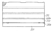
さらに、段ボールよりなる横梁材2は、前記した桁材10の凹欠部15に対応する幅と高さを有するように1枚の段ボール素板をその断面形状が扁平な四角形となるように折曲線より巻回して積層重合して形成したものであって、図示するものは図9に示すように、芯板部201の側縁に切込線入りの折曲線201aを介して折返板部202を連設するとともに、該折返板部202から順次折曲線202aを介して重合板部202を連設した段ボール素板を、断面形状が扁平な四角状となるように巻回して積層重合して形成することが製造が容易で好ましいが、多数の段ボール切断片を桁材10の凹欠部15に対応する幅と高さを有するように接着材で一体としたものであってもよい。
【0020】
【発明の効果】
本発明は前記した実施例による説明から明らかなように、桁材と横梁材とを桁材の凹欠部において組み込んで上面が各桁材と横梁材の上面による水平なデッキ支持面に形成するとともに、横梁材の下面が各桁材間から挿入されるフォーク爪の支持面に形成された格子状のベース材とし、このベース材の水平なデッキ支持面にデッキ材を接着固定したものであるから、デッキ面に重量物をのせられた場合にもデッキ材が歪むことが無く、また、フォーク爪はデッキ材の下面に直接接触することがなく強度的に優れた横梁材の下面を支えることとなるので、デッキ材は強い強度を必要とせず、しかも、桁材は打ち抜き加工した1枚の段ボール素板を折曲すればよいので、多数枚の段ボールを接着剤で積層一体した桁材を使用したものに比べて製造に手数を要しないうえに接着剤の使用量も少なくできて安価に製造できるものである。また、段ボールよりなる四角筒状の桁材の内部に補助脚板部を立設してあるものは、上下方向の荷重がこの桁材の外側脚板部のみならず補助脚板部と外側脚板部の双方により支えられることとなるので、桁材の強度はより優れたものとなって耐久性の点で一層好ましいものとなる。
従って、本発明は従来の段ボール製パレットの問題点を解決したものとして業界にもたらす益大なものである。
【図面の簡単な説明】
【図1】本発明に係る段ボール製パレットの実施の形態を示す分解斜視図である。
【図2】本発明に用いられた桁材の実施の形態を示す斜視図である。
【図3】桁材組立用の段ボール素板を示す平面図である。
【図4】桁材の組立工程を示す斜視図である。
【図5】桁材の組立工程を示す斜視図である。
【図6】桁材の組立工程を示す斜視図である。
【図7】桁材の組立工程を示す斜視図である。
【図8】連結板組立用の段ボール素板を示す平面図である。
【図9】横梁材組立用の段ボール素板を示す平面図である。
【符号の説明】
1 ベース材
2 横梁材
3 デッキ材
4 連結板
10 四角筒状の桁材
11 上板部
12 外側脚板部
13 底板部
14 補助脚板部
15 凹欠部
41 切欠部
41a 折曲線
42 連結片部
111 スリット孔
151 舌片
152 切欠部[0001]
TECHNICAL FIELD OF THE INVENTION
The present invention relates to a cardboard palette.
[0002]
[Prior art]
Conventional corrugated cardboard pallets usually consist of a number of corrugated cardboard laminated with an adhesive, a plurality of girder members arranged in parallel at a required interval, and a deck material directly adhered and fixed to the upper and lower surfaces of these. there were.
[0003]
[Problems to be solved by the invention]
However, in such a conventional device, when a load is applied to the deck surface between the girder materials, the deck material may be distorted and damaged, and a girder obtained by laminating and integrating a large number of cardboards with an adhesive. The material has the problem that it takes time and effort to manufacture and becomes heavy.
[0004]
[Means for Solving the Problems]
A corrugated cardboard pallet of the present invention made to solve the above-mentioned problem is a corrugated cardboard pallet in which a deck material made of corrugated cardboard is bonded and fixed to an upper surface of a base material assembled using a plurality of girder members made of corrugated cardboard as a main material. A square tubular girder having a concave notch for engaging a cross beam on the upper surface is disposed at a predetermined interval as the base member, and these girder members are formed as recesses. The upper surface is formed as a horizontal deck support surface by each girder material and the cross beam material by being connected in a lattice shape with a plurality of cross beam materials made of cardboard arranged in the orthogonal direction by partially engaging with the notch. Along with this, the lower surface of the cross beam is formed on the supporting surface of the fork claw inserted from between the respective girder members, and the rectangular tube-shaped girder member is located below the left and right sides of the upper plate portion. Link the outer leg plate through the folding curve At the same time, a bottom plate of approximately half the width of the upper plate is continuously connected to the lower end of the outer leg plate via an inward folding curve, and an upward auxiliary leg plate is erected at the end of the bottom plate via the folding curve. On the upper part of the girder main body, each of the above-mentioned folded corrugated cardboards is provided with a plurality of concave notches, which are partially cut out from the upper plate, the outer leg plate, and the upper part of the auxiliary leg plate at a required interval. The tongue is bent from the curve to form a square tube, and a tongue is connected to the upper end edge of the recess through a bend. A slit hole is provided in the upper plate portion, a connecting plate is inserted from the slit hole, and an auxiliary leg plate portion is held in a notch provided in the connecting plate. in one formed by folding back the connecting piece of the two having a notch by bending lines of two rows of central Further, a corrugated cardboard plate forming the square tubular girder is provided with a fold curve at an interval in the center, an upper plate portion is formed therebetween, and a fold curve is formed from the fold curve to an outer portion. Forming an outer leg plate portion between the folding curves, forming a bottom plate portion having a half width of the upper plate portion by providing a folding curve at a half width of the upper plate portion from the folding curve. An auxiliary leg plate portion having a two-piece structure including a leg plate main body portion and a folded leg plate portion is formed outside the folding curve by a folding curve, and a square hole is formed in the outer leg plate portion at one side hole. A plurality of edges are provided at predetermined intervals so as to match the folding curve, and a folding curve is provided in an upper plate portion between the ends of both punched holes provided in the opposed outer leg plate portions, and a folding curve facing the folding curve is provided. A cutting line or a cut-out portion communicating with the cutout hole is formed at an intermediate portion between the fold curve and the cut line, and formed between the fold curve and the cut line. A notch is provided from the center of the tip of the cutting line on the tongue piece to be cut, and a plurality of slits are provided in the upper plate portion in the transverse direction for connecting plate insertion at a required interval, and the leg plate body portion by the folding curve ). A double-width punched hole is formed in the auxiliary leg plate that has a double structure with the folded-back leg plate in correspondence with the above-mentioned hole centering on the folding curve to form a notch step for forming a concave notch when folded. Further, the auxiliary leg plate portion is formed with a horizontally long hole for forming a cutout portion for fitting the head of the connecting plate at the time of turning back, corresponding to the slit, centering on the folding curve. This is defined as the invention according to
[0005]
And, as the cross beam of the base material made of the corrugated cardboard according to the invention according to
[0006]
[0007]
BEST MODE FOR CARRYING OUT THE INVENTION
Next, a preferred embodiment of the present invention will be described with reference to the drawings.
[0008]
The pallet made of corrugated cardboard thus configured has a horizontal shape formed by the
[0009]
As shown in FIG. 2, the above-mentioned
[0010]
In this manner, the square
[0011]
Further, this
[0012]
Further, the outer
[0013]
Further, the auxiliary
[0014]
Then, as shown in FIG. 4, the corrugated cardboard blank thus punched out is bent 360 ° via the
[0015]
Thereafter, each
[0016]
[0017]
A plurality of the
[0018]
Further, as shown in FIGS. 7 and 8, the connecting
[0019]
Further, the cross beam member 2 made of corrugated cardboard is formed by folding a single corrugated cardboard plate so as to have a width and a height corresponding to the
[0020]
【The invention's effect】
As is clear from the description of the above-described embodiment, the present invention incorporates a girder material and a cross beam material in a concave notch of a girder material and forms an upper surface on a horizontal deck support surface formed by the upper surfaces of the respective girder materials and the cross beam material. In addition, the lower surface of the cross beam material is a lattice-like base material formed on the support surface of the fork claw inserted from between each girder material, and the deck material is bonded and fixed to the horizontal deck support surface of this base material. Therefore, even if a heavy object is placed on the deck surface, the deck material is not distorted, and the fork claws do not directly contact the lower surface of the deck material and support the lower surface of the cross beam material which is excellent in strength Therefore, the deck material does not need strong strength, and the girder material can be obtained by bending a single punched corrugated cardboard plate. Manufactured compared to used Those which can be produced inexpensively made smaller amount of glue on top does not require the trouble. In addition, in the case where the auxiliary leg plate portion is erected inside a square tubular girder made of corrugated cardboard, the load in the vertical direction is not only on the outer leg plate portion of this girder material, but also on both the auxiliary leg plate portion and the outer leg plate portion. Therefore, the strength of the girder material becomes more excellent, which is more preferable in terms of durability.
Accordingly, the present invention is of great benefit to the industry as solving the problems of conventional cardboard pallets.
[Brief description of the drawings]
FIG. 1 is an exploded perspective view showing an embodiment of a cardboard pallet according to the present invention.
FIG. 2 is a perspective view showing an embodiment of a girder used in the present invention.
FIG. 3 is a plan view showing a corrugated board for assembling a girder material.
FIG. 4 is a perspective view showing a process of assembling the beam members.
FIG. 5 is a perspective view showing a step of assembling the beam members.
FIG. 6 is a perspective view showing a step of assembling the beam members.
FIG. 7 is a perspective view showing a step of assembling the beam members.
FIG. 8 is a plan view showing a cardboard blank for assembling a connecting plate.
FIG. 9 is a plan view showing a corrugated board for assembling a cross beam member.
[Explanation of symbols]
1 Base material 2 Cross beam 3
10 Square tube girder
11 Upper plate
12 Outer leg plate
13 Bottom plate
14 Auxiliary leg plate
15 Notch
41 Notch
41a folding curve
42 connecting piece
111 slit hole
151 Tongue Piece
152 Notch
Claims (2)
Priority Applications (1)
| Application Number | Priority Date | Filing Date | Title |
|---|---|---|---|
| JP2001070451A JP3573720B2 (en) | 2001-03-13 | 2001-03-13 | Cardboard pallets |
Applications Claiming Priority (1)
| Application Number | Priority Date | Filing Date | Title |
|---|---|---|---|
| JP2001070451A JP3573720B2 (en) | 2001-03-13 | 2001-03-13 | Cardboard pallets |
Publications (2)
| Publication Number | Publication Date |
|---|---|
| JP2002274538A JP2002274538A (en) | 2002-09-25 |
| JP3573720B2 true JP3573720B2 (en) | 2004-10-06 |
Family
ID=18928326
Family Applications (1)
| Application Number | Title | Priority Date | Filing Date |
|---|---|---|---|
| JP2001070451A Expired - Lifetime JP3573720B2 (en) | 2001-03-13 | 2001-03-13 | Cardboard pallets |
Country Status (1)
| Country | Link |
|---|---|
| JP (1) | JP3573720B2 (en) |
-
2001
- 2001-03-13 JP JP2001070451A patent/JP3573720B2/en not_active Expired - Lifetime
Also Published As
| Publication number | Publication date |
|---|---|
| JP2002274538A (en) | 2002-09-25 |
Similar Documents
| Publication | Publication Date | Title |
|---|---|---|
| KR101014448B1 (en) | Corrugated board packaging assembly | |
| JP2693715B2 (en) | Girder material and pallet using the girder material | |
| JP3573720B2 (en) | Cardboard pallets | |
| JP2005153917A (en) | Package for transportation | |
| KR101759505B1 (en) | Assembly corrugated cardboard table | |
| JPH0755710B2 (en) | Cardboard pallets | |
| JP4318351B2 (en) | Pallet for conveyance | |
| JP2018047952A (en) | Corrugated cardboard pallet and method for assembling the same | |
| JP4240449B2 (en) | Cardboard pallets | |
| JP4064519B2 (en) | Cardboard tray | |
| JP3101227U (en) | Cardboard pallets | |
| JP4031970B2 (en) | Paper pallet and box with paper pallet | |
| JP3223812U (en) | Box sheet | |
| JP4240229B2 (en) | Cardboard pallets | |
| JP3498071B2 (en) | Girder member and pallet using the girder member | |
| JP3135773U (en) | Girder, skid and pallet using the same | |
| JP2013227024A (en) | Pallet for conveyance | |
| JP4002570B2 (en) | Paper pallet | |
| JP3109432U (en) | Paper pallet support and paper pallet | |
| JP6574509B1 (en) | Assembled storage box and blank set | |
| JP4002573B2 (en) | Paper pallet | |
| JPH0619462Y2 (en) | Paper flat pallet | |
| JPH0939968A (en) | Supporting leg for pallet made of paper | |
| JP3094054U (en) | Girder for cardboard pallets | |
| JP2005320043A (en) | Corrugated fiberboard beam and paper-made pallet using the same |
Legal Events
| Date | Code | Title | Description |
|---|---|---|---|
| A521 | Written amendment |
Free format text: JAPANESE INTERMEDIATE CODE: A523 Effective date: 20040202 |
|
| A131 | Notification of reasons for refusal |
Free format text: JAPANESE INTERMEDIATE CODE: A131 Effective date: 20040413 |
|
| A521 | Written amendment |
Free format text: JAPANESE INTERMEDIATE CODE: A523 Effective date: 20040611 |
|
| TRDD | Decision of grant or rejection written | ||
| A01 | Written decision to grant a patent or to grant a registration (utility model) |
Free format text: JAPANESE INTERMEDIATE CODE: A01 Effective date: 20040625 |
|
| A61 | First payment of annual fees (during grant procedure) |
Free format text: JAPANESE INTERMEDIATE CODE: A61 Effective date: 20040629 |
|
| R150 | Certificate of patent or registration of utility model |
Free format text: JAPANESE INTERMEDIATE CODE: R150 |
|
| FPAY | Renewal fee payment (event date is renewal date of database) |
Free format text: PAYMENT UNTIL: 20100709 Year of fee payment: 6 |