JP3573216B2 - Method and apparatus for cutting sheet glass - Google Patents
Method and apparatus for cutting sheet glass Download PDFInfo
- Publication number
- JP3573216B2 JP3573216B2 JP05068694A JP5068694A JP3573216B2 JP 3573216 B2 JP3573216 B2 JP 3573216B2 JP 05068694 A JP05068694 A JP 05068694A JP 5068694 A JP5068694 A JP 5068694A JP 3573216 B2 JP3573216 B2 JP 3573216B2
- Authority
- JP
- Japan
- Prior art keywords
- sheet glass
- cutting
- cutter
- cutter wheel
- reaction force
- Prior art date
- Legal status (The legal status is an assumption and is not a legal conclusion. Google has not performed a legal analysis and makes no representation as to the accuracy of the status listed.)
- Expired - Fee Related
Links
Images


Classifications
-
- C—CHEMISTRY; METALLURGY
- C03—GLASS; MINERAL OR SLAG WOOL
- C03B—MANUFACTURE, SHAPING, OR SUPPLEMENTARY PROCESSES
- C03B33/00—Severing cooled glass
- C03B33/02—Cutting or splitting sheet glass or ribbons; Apparatus or machines therefor
- C03B33/023—Cutting or splitting sheet glass or ribbons; Apparatus or machines therefor the sheet or ribbon being in a horizontal position
- C03B33/027—Scoring tool holders; Driving mechanisms therefor
Landscapes
- Chemical & Material Sciences (AREA)
- Engineering & Computer Science (AREA)
- Materials Engineering (AREA)
- Organic Chemistry (AREA)
- Re-Forming, After-Treatment, Cutting And Transporting Of Glass Products (AREA)
Description
【0001】
【産業上の利用分野】
本発明は板ガラスにカッタホイールを押圧し、押圧されたカッタホイールを移動して板ガラスに切線を加工する板ガラスの切断方法及び装置に関する。
【0002】
【従来の技術】
板ガラスを所望の形状に切断する場合、先ず板ガラスに押圧したカッタホイール等のカッタ部材を切断方向に移動して板ガラスの表面に切線を加工し、切線加工後、切線で板ガラスを折って所望の形状に切断する。
【0003】
【発明が解決しようとする課題】
しかしながら、板ガラスを切線で折る場合、板ガラス表面に切線が適正に加工されていないと、板ガラスの折り損じが生じたり、板ガラスの折面が不良になるという問題がある。
また、カッタ部材が切線加工開始位置に適正に位置決めされていない状態でカッタ部材を走行すると、カッタ部材が板ガラスの端部に衝突する等の切線加工開始時の不具合が生じるという問題がある。
【0004】
本発明はこのような事情に鑑みてなされたもので、切線の加工状態を最適に維持して板ガラスの折り損じを防止すると共に良好な折面を得ることができ、さらに、切線加工開始時の不具合をなくすことができる板ガラスの切断方法及び装置を提供することを目的とする。
【0005】
【課題を解決するための手段】
本発明は、前記目的を達成する為に、板ガラスに押圧されたカッタ部材を移動して板ガラスの表面に切線を加工する板ガラスの切断方法において、前記カッタ部材を介して前記板ガラスから受ける反力の大きさと方向を検出し、該検出した反力の大きさと方向に基づいて前記切線の良否を判定することを特徴とする板ガラスの切断方法、及び、それを実施するための装置である。
【0006】
また、本発明は、前記目的を達成する為に、板ガラスに押圧されたカッタ部材を移動して板ガラスの表面に切線を加工する板ガラスの切断方法において、前記カッタ部材を前記板ガラスの切線加工位置まで下降した時の前記カッタ部材が受ける反力の大きさと方向を検出し、該検出した反力の大きさと方向に基づいて前記板ガラスの切線加工開始位置に前記カッタ部材が適正に位置決めされているか否かを判定することを特徴とする板ガラスの切断方法、及び、それを実施するための装置である。
【0007】
【作用】
本発明によれば、板ガラスの切断装置に検出部及び判定部を備え、検出部はカッタホイールを介して板ガラスから受ける反力を検出する。そして、判定部は、検出部が検出した反力に基づいて切線が板ガラスに適切に加工されているか否かを判定する。
【0008】
また、本発明によれば、検出部はカッタ部材を板ガラスの切線加工位置まで下降した時のカッタ部材が受ける反力の大きさと方向を検出する。そして、判定部は、検出部が検出した反力の大きさと方向に基づいて板ガラスの切線加工開始位置にカッタ部材が適正に位置決めされているか否かを判定する。
【0009】
【実施例】
実施例1、
以下添付図面に従って本発明に係る板ガラスの切断方法及び装置について詳説する。図1は本発明に係る板ガラスの切断装置の断面図、図2はそのブロック図である。図1に示すように板ガラスの切断装置10は加圧機構12を備え、加圧機構12にはシャフト16が支持されている。
【0010】
シャフト16の下端部には後述するセンサ28を介して支持部材30が固定され、支持部材30にはベアリング32を介してホルダ34の軸部34Aが回動自在に支持されている。ホルダ34の下端部にはピン35を介して前述したカッタホイール36が回動自在に支持され、ピン35の軸芯は軸部34Aの軸芯から後方にL1 だけオフセットされている。このように、ピン35の軸芯は軸部34Aの軸芯から後方にL1 だけオフセットされているので、板ガラスの切断装置10が切断方向(矢印A方向)に移動すると、カッタホイール36は切断方向に対して平行に保持される。カッタホイール36は円板状に形成され、板ガラス14の表面上を回転しながら移動して板ガラス14に切線を加工する。
【0011】
図2に示すように板ガラスの切断装置10は検出部41及び判定部42を備え、検出部41は前述したセンサ28、データ処理部40を有している。センサ28には1例として3成分の力センサが使用され、力センサ28にはカッタホイール36等を介して板ガラス14の反力が伝達される。この反力はX方向、Y方向及びZ方向の分力からなり、力センサ28は伝達されたX方向、Y方向及びZ方向の分力を電気信号に変換する。
【0012】
この場合、図2に示すようにY方向の分力はカッタホイール36の進行方向に対して反対方向に作用し、Z方向の分力はカッタホイール36を上方に押し上げるように作用する。また、X方向の分力はカッタホイール36の進行方向に対して直交する方向に作用する。データ処理部40には力センサ28で電気信号に変換されたX方向、Y方向及びZ方向の分力信号が伝達され、データ処理部40は伝達されたX方向、Y方向及びZ方向の分力信号に基づいてX方向、Y方向及びZ方向の分力を求める。
【0013】
ここで、進行方向反力又はみかけの摩擦係数μ(=Y/Z)、X方向分力(又はX/Z)及びZ方向分力に基づいて切線加工状態を判定する場合について説明する。みかけの摩擦係数μはカッタホイール36の回転状態等の判定に使用される。すなわち、みかけの摩擦係数μが大きいときはカッタホイール36が回転しなくなって、板ガラス14の表面上を滑っている様なときである。これに対し、みかけの摩擦係数μが小さいときはカッタホイール36が良好に回転し、カッタホイール36が板ガラス14の表面に適正な切線を加工しているときである。
【0014】
従って、切線が適正に加工される場合と適正に加工されない場合とを区分けするみかけの摩擦係数μのしきい値をデータとして求めておけば、判定部42は、データ処理部40で求めたみかけの摩擦係数μとしきい値とを比較してカッタホイール36の回転の良否を判定することができる。
また、X方向分力又はX/Zによって進行方向に対するカッタホイール36の傾きを検知することができる。カッタホイール36に傾きが生じる原因としては、次に示すもの等が種々あげられる。
【0015】
(1)装置の角度調整不足
(2)ベアリング32(図1、図2参照)の回転不良
(3)カッタホイール36の摩耗等で板ガラス14に対するカッタホイール36の食い込み不足等が生じ、キャスタ効果が充分に発揮されない場合
(4)カッタホイール36の稜線36A(図1参照)のズレ不良
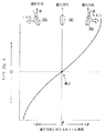
さらに、図3に示すようにカッタホイール36の傾きθが0のときX方向分力又はX/Zがほぼ0であり、カッタホイール36の傾きθが大きくなるに従ってX方向分力又はX/Zの絶対値が増大してくる。そして、カッタホイール36の傾きθが大きくなると切線不良が発生するので、X方向分力又はX/Zのしきい値を設定し、設定したしきい値とX方向分力又はX/Zの絶対値とを比較判定することによって、カッタホイール36の傾きによる切線不良を防止することが可能である。
【0016】
次いで、Z方向分力について説明する。Z方向分力は、例えばシャフト16と軸受(図示せず)との摩擦が増大して切圧が不安定の場合や、カッタホイール36の加圧機構に異常が発生した場合等に不安定になる。この場合、カッタホイール36の板ガラス14に対する押圧力が不安定になるので、板ガラス14に適切な切線を加工することができない。従って、切線が適正に加工される場合と適正に加工されない場合とを区分けするZ方向分力の不安定度のしきい値を設定することにより、判定部42は、データ処理部40で求めたZ方向分力のデータとしきい値とを比較して板ガラス14の切線状態の良否を判定する。
【0017】
また、Z方向分力が一定周期で変動する場合、カッタホイール36の形状異常の判定が可能である。例えば図4に示すようにカッタホイール36がe偏心している場合、カッタホイール36が1回転すると図2、図4の測定長Lは破線で示すような最大変位2eの山形の曲線で変化する。従って、偏心しているカッタホイール36で切線を加工するとZ方向分力(すなわち、真の押付力)は図5の(2)に示すように山形の部分が一定の周期で表れ、板ガラス14に適正な切線を加工することができない。
【0018】
従って、切線が適正に加工される場合と適正に加工されない場合とを区分けするZ方向分力の変動しきい値をデータとして求めることにより、判定部42は、データ処理部40で求めた一定周期で変化するデータと変動しきい値とを比較してカッタホイール36の同心度の良否を判定して、切線が不安定にならないようにする。また、この方法を採用してカッタホイール36の真円度の良否を判定することも可能である。なお、図4において実線のグラフは偏心等がなく正常なカッタホイール36のデータを示し、この場合、図5の(1)に示すようにZ方向分力に一定の周期的変動が少なく、安定したZ方向分力になる。
【0019】
さらに、Z方向分力の一定周期の変動は、カッタホイール36の真円度及び同心度の良否の判定の他に、カッタホイール36の稜線の局部欠陥や局部摩耗の判定、さらに、カレット等の異物のかみ込みや異物のひっかかり等のカッタホイール36の回転系の異常の判定に使用することが可能である。すなわち、判定部42は、データ処理部40で求めた一定周期で変化するデータとしきい値とを比較してこれらの不具合が発生しているか否かを判定することが可能である。また、Z方向分力が一定周期で変動する場合、約5 kHz〜50kHzの高周波域のデータをデータ処理部40で求めて、判定部42がデータ処理部40で求めた高周波域のデータを判定して切線に発生する微細クラックの進行状態を判定することも可能である。
【0020】
このように、判定部42は、X方向、Y方向及びZ方向の分力やみかけの摩擦係数μ更にはX/Zの各々のしきい値と検出部41で求めた各々の値とを比較して切線の良否を判定する。そして、判定部42の判定結果に基づいてカッタホイール36やピン35等を交換する。また、判定部42で判定した結果、加工条件(カッタホイール36の切圧、切速度、旋回角度等)の変更や補正で対応できる場合には、カッタホイール36やピン35等を交換しないで加工条件の変更や補正で対応する。
【0021】
例えば、検出部41で検出したX方向分力又はX/Zの値がしきい値の近傍にある場合、検出した値がしきい値を越えないように、板ガラスの切断装置10のカッタ部の旋回角度を変更する。また、検出部41で検出したみかけの摩擦係数μの値がしきい値の近傍にある場合、検出したみかけの摩擦係数μの値がしきい値を越えないように、板ガラスの切断装置10の切圧を高く変更することにより、カッタホイール36が板ガラス14に強く食い込むので板ガラス14に適正な切線を加工することができる。
【0022】
このように、判定部42が判定した判定結果に基づいて、カッタホイール36やピン35等を交換したり、加工条件を変更、補正することにより、板ガラスの切断装置10は、最適な切線が板ガラス14に加工されるように管理することができる。なお、図2上で46は増幅部、48は板ガラス14が載置されるテーブルである。
【0023】
さらに、カッタホイール36の反力、すなわち、X方向、Y方向及びZ方向の分力を求めることにより、前述した判定の他に板ガラスの切断装置10の調整事項を定量化して管理することも可能である。例えば、X方向、Y方向及びZ方向の分力に基づいてカッタホイール36の下降時の衝撃力を適正に設定してタッチハマ等の発生を防止することができ、また、高圧状態から切圧状態への切替ポイントを最適に設定して機械系遅れに無関係な真の切替ポイントを得ることができる。さらに、カッタホイール36の首振り角度と進行方向との合致を判定することができ、これにより、例えば操作ミスでカッタホイール36を障害物又はガラスエッジ等に衝突させて、首振り角度がズレた場合の角度調整が容易になりまた、切線加工中に、例えばX方向の切りが適正で、Y方向の切りが不適正であるという判定が可能になる。
【0024】
実施例2、
実施例1では板ガラスの切断装置10に判定部42を備えて、X方向、Y方向及びZ方向の分力やみかけの摩擦係数μ又はX/Zの各々のしきい値と、検出部41で求めた各々の値とを比較して、求めた値がしきい値を越えた時切線状態が悪いと判定する場合について説明したが、さらに表示部を設けて検出部41で求めた各々の値を常時表示するようにしてもよい。なお、判定部42を使用せずに表示部のみを使用してもよい。
【0025】
実施例3、
実施例1、2では検出部41で求めたX方向、Y方向及びZ方向の分力やみかけの摩擦係数μ又はX/Zの値に基づいて切線状態の良否を判定する場合について説明したが、これに限らず、カッタホイール36に発生する振動成分を検知して切線の良否を判定することも可能である。すなわち、板ガラスの表面に切線を加工する場合、カッタホイール36を板ガラスの表面に沿って走行させて板ガラスの表面をカッタホイール36で砕いて板ガラスの表面に切線を加工するが、カッタホイール36で板ガラスの表面を砕く場合にカッタホイール36に上下方向の振動が発生する。
【0026】
従って、1成分又は多成分方向の反力センサや加速度センサ等を使用して、切線の加工中にカッタホイール36に発生する高周波域(5kHz〜50kHz)振動成分を検知して、検知したカッタホイール36の振動成分を音に変換し、この音に基づいて切線の良否を判定することが可能である。また、1成分又は多成分方向の反力センサや加速度センサに代えて、マイクロホンを使用して板ガラスの表面に切線を加工する際の音を直接検知して、検知した音に基づいて切線の良否を判定することも可能である。
【0027】
さらに、1成分又は多成分方向の反力センサや加速度センサ等を使用して検知したカッタホイール36の振動成分を周波数解析して、この解析結果に基づいて切線の良否を判定することも可能である。また、マイクロホンを使用して検知した切欠加工音を周波数解析して、この解析結果に基づいて切線の良否を判定することも可能である。
【0028】
実施例4、
実施例1〜3では反力センサ等で検知した値に基づいて切線の良否を判定する場合について説明したが、これに限らず、反力センサを使用することによりカッタホイール36が板ガラスの切線加工開始位置に適正に位置決めされているか否かを判定することをができる。以下図6〜図10により実施例4について説明する。なお、図6〜図8上で実施例1と同一類似部材については同一符号を付して説明を省略する。
【0029】
図6はカッタホイール36を板ガラス14の切線加工開始位置に適正に位置決めする動作を説明する図であり、同図に示すようにカッタホイール36は、下降して板ガラス14の表面を押圧し、この状態で矢印方向に走行して板ガラス14の表面に切線を加工する。そして、カッタホイール36が下降して切線加工開始位置に適正に位置決めされると、カッタホイール36は板ガラス14から一定の大きさのZ成分反力を受ける。このZ成分反力は図2に示す検出部41で検知される。
【0030】
一方、図7に示すようにカッタホイール36が板ガラス14から外れた位置に位置決めされた場合、カッタホイール36を図6の場合と同様に下降させると、カッタホイール36は板ガラス14の表面を押圧しないで、板ガラス14の表面下側まで下降する。従って、この状態でカッタホイール36を矢印方向に走行させると、カッタホイール36が板ガラス14の端部に衝突し、この衝突による衝撃で次の不具合が生じる場合がある。
【0031】
(1)力センサ28の破損
(2)カッタホイール36の破損
(3)カッタホイール36の傾き角度のズレ発生
(4)カッタホイール36の局所欠損
(5)カッタヘッド全体の損傷
これらの不具合を解消するために、検出部41でカッタホイール36を切線加工開始位置まで下降したときのカッタホイール36に作用するZ成分反力を検知し、検知したZ成分反力がしきい値より小さい場合に判定部42(図2参照)でカッタホイール36を矢印方向に走行しないように制御する。
【0032】
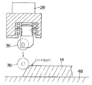
また、図8に示すように板ガラス14の端部が傾斜面状に折られている場合、切線加工開始位置まで下降したカッタホイール36が傾斜面に当接した状態で矢印方向に走行すると、板ガラス14にハマ欠けが発生する場合がある。この場合、カッタホイール36が切線加工開始位置まで下降して傾斜面に当接すると、カッタホイール36は板ガラス14の傾斜面からZ成分反力及びY成分反力を受ける。従って、これらの不具合を解消するために、検出部41でカッタホイール36が切線加工開始位置まで下降したときのZ成分反力及びY成分反力を検知し、検知したZ成分反力及びY成分反力に基づいてY/Z値を求め、判定部42で求められたY/Z値としきい値とを比較して、求められたY/Z値がしきい値を越えた場合にカッタホイール36を矢印方向に走行しないように制御する。また、Yだけに着目しても同様の制御は可能である。
【0033】
以下図9、図10のフローチャートに基づいてカッタホイール36が板ガラス14の切線加工開始位置に適正に位置決めされているか否かを判定する方法について説明する。先ず、図9に基づいて入力ミス、データ転送ミス等により切りデータが正確に入力されないときのカッタホイール36の制御について説明する。切線加工を開始する際に、切りデータを入力又は転送してスタート信号を出力する。これにより、カッタホイール36が原点位置に位置決めされ、切線加工開始位置まで下降される(ステップ70)。次に、検出部41でカッタホイール36に作用するZ成分反力を検知し、検知したZ成分反力としきい値とを比較する(ステップ72)。
【0034】
比較した結果Z成分反力がしきい値以下の場合、カッタホイール36を上昇する(ステップ74)。次いで、カッタホイール36を原点位置まで走行して待機させる(ステップ76)。続いて、切りデータを補正して切線加工を再スタートさせる(ステップ78)。一方、比較した結果Z成分反力がしきい値を越えた場合、カッタホイール36を走行させて板ガラス14の表面に切線を加工する(ステップ80)。これにより、カッタヘッドと板ガラス14の端部との衝突を阻止することができる。
【0035】
次に、図10に基づいて端部が傾斜面状に折られた板ガラス14に切線を加工するときのカッタホイール36の制御について説明する。切線加工を開始する際に、切りデータを入力又は転送してスタート信号を出力する。これにより、カッタホイール36が原点位置に位置決めされ、切線加工開始位置まで下降される(ステップ84)。次に、検出部41でカッタホイール36に作用するZ成分反力及びY成分反力を検知し、検知したZ成分反力及びY成分反力に基づいてY/Z値を求め、Y/Z値としきい値とを比較する(ステップ86)。
【0036】
比較した結果Y/Z値がしきい値以上の場合、カッタホイール36を上昇する(ステップ88)。次いで、カッタホイール36を数mm前進させて(ステップ90)、切線加工を再スタートさせる。一方、比較した結果Y/Z値がしきい値以下の場合、カッタホイール36を走行させて板ガラス14の表面に切線を加工する(ステップ92)。これにより、傾斜面状に折られた板ガラス14の端部にカッタホイール36が当接した状態で切線を加工しないようにすることができる。
【0037】
実施例5、
実施例1〜4では本願発明をエアシリンダ式の加圧機構部を備えた板ガラスの切断装置10に適用した場合について説明したが、これに限らず、本願発明を送りねじを駆動モータで回転する等のその他の加圧機構部を備えた板ガラスの切断装置に適用することも可能である。
【0038】
実施例6、
実施例1〜4ではカッタホイール36で板ガラス14に切線を加工する場合について説明したが、これに限らず、本発明に係る板ガラスの切断装置はガラススクライバー等のその他のカッタ部材で板ガラス14に切線を加工する場合にも適用することも可能である。
【0039】
【発明の効果】
以上説明したように本発明に係る板ガラスの切断方法及び装置によれば、板ガラスの切断装置に検出部及び判定部を備え、検出部はカッタホイールを介して板ガラスから受ける反力を検出する。そして、判定部は、検出部が検出した反力に基づいて切線が板ガラスに適切に加工されているか否かを判定する。このように、切線が適切に加工されているか否かを判定することにより、切線の加工状態を最適に維持して板ガラスの折り損じを防止すると共に良好な折面を得ることができる。
【0040】
また、本発明によれば、検出部はカッタ部材を板ガラスの切線加工位置まで下降した時のカッタ部材が受ける反力の大きさと方向を検出する。そして、判定部は、検出部が検出した反力の大きさと方向に基づいて板ガラスの切線加工開始位置にカッタ部材が適正に位置決めされているか否かを判定する。従って、切線加工開始時の不具合の発生をなくすことができる。
【図面の簡単な説明】
【図1】本発明に係る板ガラスの切断装置の断面図
【図2】本発明に係る板ガラスの切断装置のブロック図
【図3】カッタホイールが進行方向に対する傾きとX方向分力又はX/Zを示すグラフ
【図4】カッタホイールが偏心している場合や偏心していない場合のカッタ先端までの測定長を示すグラフ
【図5】図4の(1)、(2)の場合のZ成分力の周期的変動を示すグラフ
【図6】切線加工開始時のカッタホイール動作を説明する説明図
【図7】切線加工開始時のカッタホイール動作を説明する説明図
【図8】切線加工開始時のカッタホイール動作を説明する説明図
【図9】切線加工開始時のカッタホイール動作を説明するフローチャート
【図10】切線加工開始時のカッタホイール動作を説明するフローチャート
【符号の説明】
10…板ガラスの切断装置
14…板ガラス
28…力センサ
36…カッタホイール
40…データ処理部
41…検出部
42…判定部[0001]
[Industrial applications]
The present invention relates to a method and an apparatus for cutting a glass sheet, in which a cutter wheel is pressed against the glass sheet, and the pressed cutter wheel is moved to make a cutting line in the glass sheet.
[0002]
[Prior art]
When cutting a sheet glass into a desired shape, first, a cutter member such as a cutter wheel pressed against the sheet glass is moved in a cutting direction to form a cutting line on the surface of the sheet glass. After the cutting line processing, the sheet glass is folded at the cutting line to obtain a desired shape. Cut into pieces.
[0003]
[Problems to be solved by the invention]
However, when the sheet glass is folded along the cutting line, if the cutting line is not properly processed on the surface of the sheet glass, there is a problem that the sheet glass is broken or the folding surface of the sheet glass becomes defective.
In addition, when the cutter member travels in a state where the cutter member is not properly positioned at the cutting line processing start position, there is a problem that a problem occurs at the time of starting the cutting line processing, such as the collision of the cutter member with the edge of the sheet glass.
[0004]
The present invention has been made in view of such circumstances, and it is possible to prevent breakage of a sheet glass and to obtain a good folded surface while maintaining the processing state of the cutting line optimally. It is an object of the present invention to provide a method and an apparatus for cutting sheet glass, which can eliminate defects.
[0005]
[Means for Solving the Problems]
The present invention, in order to achieve the above object, in a method of cutting a sheet glass by moving a cutter member pressed against the sheet glass to cut a line on the surface of the sheet glass, the reaction force received from the sheet glass via the cutter member A method for cutting a sheet glass, comprising detecting a size and a direction, and judging the quality of the cut line based on the magnitude and direction of the detected reaction force, and an apparatus for performing the method.
[0006]
Further, in order to achieve the above object, the present invention provides a method for cutting a sheet glass by moving a cutter member pressed by a sheet glass to form a cutting line on the surface of the sheet glass, wherein the cutting member is moved to a cutting line processing position of the sheet glass. Detecting the magnitude and direction of the reaction force received by the cutter member when the cutter member is lowered, and determining whether the cutter member is appropriately positioned at the cutting line processing start position of the sheet glass based on the magnitude and direction of the detected reaction force. the method of cutting sheet glass and judging whether, and an apparatus for carrying it.
[0007]
[Action]
According to the present invention, the sheet glass cutting device includes the detecting unit and the determining unit, and the detecting unit detects a reaction force received from the sheet glass via the cutter wheel. Then, the determination unit determines whether or not the cut line is appropriately processed on the sheet glass based on the reaction force detected by the detection unit.
[0008]
Further, according to the present invention, the detection unit detects the magnitude and direction of the reaction force received by the cutter member when the cutter member is lowered to the cutting position of the sheet glass. Then, the determination unit determines whether or not the cutter member is appropriately positioned at the cutting line starting position of the sheet glass based on the magnitude and direction of the reaction force detected by the detection unit.
[0009]
【Example】
Example 1,
Hereinafter, a method and an apparatus for cutting a sheet glass according to the present invention will be described in detail with reference to the accompanying drawings. FIG. 1 is a sectional view of a sheet glass cutting apparatus according to the present invention, and FIG. 2 is a block diagram thereof. As shown in FIG. 1, the sheet glass cutting apparatus 10 includes a
[0010]
A
[0011]
As shown in FIG. 2, the sheet glass cutting apparatus 10 includes a
[0012]
In this case, as shown in FIG. 2, the component force in the Y direction acts in a direction opposite to the traveling direction of the
[0013]
Here, a case where the cutting line processing state is determined based on the reaction force in the traveling direction or the apparent friction coefficient μ (= Y / Z), the component force in the X direction (or X / Z), and the component force in the Z direction will be described. The apparent friction coefficient μ is used for determining the rotation state of the
[0014]
Therefore, if the threshold value of the apparent friction coefficient μ for distinguishing between the case where the cutting line is properly processed and the case where the cutting line is not properly processed is determined as data, the
Further, the inclination of the
[0015]
(1) Insufficient angle adjustment of the device (2) Poor rotation of the bearing 32 (see FIGS. 1 and 2) (3) Insufficient biting of the
[0016]
Next, the Z-direction component force will be described. The component force in the Z direction becomes unstable, for example, when the friction between the
[0017]
Further, when the component force in the Z direction fluctuates at a constant cycle, it is possible to determine the shape abnormality of the
[0018]
Accordingly, by determining as a data the variation threshold value of the component force in the Z direction, which separates the case where the cutting line is properly processed and the case where the cutting line is not properly processed, the
[0019]
Furthermore, the fluctuation of the component force in the Z direction at a constant cycle is not only the determination of the roundness and the concentricity of the
[0020]
As described above, the
[0021]
For example, when the value of the component force in the X direction or the value of X / Z detected by the
[0022]
As described above, based on the determination result determined by the
[0023]
Further, by calculating the reaction force of the
[0024]
Example 2,
Includes a
[0025]
Example 3,
X-direction was determined by the
[0026]
Therefore, a high-frequency (5 kHz to 50 kHz) vibration component generated in the
[0027]
Further, it is also possible to analyze the vibration component of the
[0028]
Example 4,
In the first to third embodiments, the case where the quality of the cutting line is determined based on the value detected by the reaction force sensor or the like has been described. However, the present invention is not limited to this, and the
[0029]
FIG. 6 is a view for explaining the operation of appropriately positioning the
[0030]
On the other hand, when the
[0031]
(1) Damage of the force sensor 28 (2) Damage of the cutter wheel 36 (3) Deviation of the inclination angle of the cutter wheel 36 (4) Local defect of the cutter wheel 36 (5) Damage of the entire cutter head The
[0032]
As shown in FIG. 8, when the edge of the
[0033]
Hereinafter, a method for determining whether or not the
[0034]
If the Z-component reaction force is equal to or smaller than the threshold value, the
[0035]
Next, a description will be given of control of the
[0036]
If the result of the comparison indicates that the Y / Z value is equal to or greater than the threshold value, the
[0037]
Example 5,
There has been described a case where the actual施例1-4 in the present invention is applied to the cutting device 10 of the glass sheet with a pressing mechanism of the air cylinder type, not limited to this, rotating the screw by the drive motor sends invention It is also possible to apply the present invention to a sheet glass cutting device provided with another pressing mechanism section.
[0038]
Example 6,
Has been described for processing the cut line in the
[0039]
【The invention's effect】
As described above, according to the sheet glass cutting method and apparatus according to the present invention, the sheet glass cutting device includes the detection unit and the determination unit, and the detection unit detects a reaction force received from the sheet glass via the cutter wheel. Then, the determination unit determines whether or not the cut line is appropriately processed on the sheet glass based on the reaction force detected by the detection unit. As described above, by determining whether or not the cut line is appropriately processed, it is possible to maintain the processing state of the cut line optimally, prevent breakage of the sheet glass, and obtain a good folded surface.
[0040]
Further, according to the present invention, the detection unit detects the magnitude and direction of the reaction force received by the cutter member when the cutter member is lowered to the cutting position of the sheet glass. Then, the determination unit determines whether or not the cutter member is properly positioned at the cutting line processing start position of the sheet glass based on the magnitude and direction of the reaction force detected by the detection unit. Therefore, it is possible to eliminate the occurrence of a trouble at the start of the cutting line processing.
[Brief description of the drawings]
FIG. 1 is a cross-sectional view of a sheet glass cutting device according to the present invention. FIG. 2 is a block diagram of a sheet glass cutting device according to the present invention. FIG. 3 is an inclination of a cutter wheel with respect to a traveling direction and a component force in X direction or X / Z. FIG. 4 is a graph showing the measurement length up to the tip of the cutter when the cutter wheel is eccentric or not eccentric. FIG. 5 is a graph showing the Z component force in the cases of (1) and (2) in FIG. FIG. 6 is a graph showing the periodic fluctuation. FIG. 6 is an explanatory diagram illustrating the operation of the cutter wheel at the start of cutting line processing. FIG. 7 is an explanatory diagram illustrating the operation of the cutter wheel at the start of cutting line processing. FIG. 9 is a flowchart for explaining the operation of the cutter wheel at the start of cutting line processing. FIG. 10 is a flowchart for explaining the operation of the cutter wheel at the start of cutting line processing.
DESCRIPTION OF SYMBOLS 10 ... Sheet
Claims (13)
前記カッタ部材を介して前記板ガラスから受ける反力の大きさと方向を検出し、該検出した反力の大きさと方向に基づいて前記切線の良否を判定することを特徴とする板ガラスの切断方法。In a method of cutting a sheet glass, in which a cutting member is moved by pressing a sheet glass and a cutting line is processed on a surface of the sheet glass,
A method for cutting a glass sheet, comprising detecting a magnitude and a direction of a reaction force received from the glass sheet via the cutter member, and determining whether the score line is good or bad based on the magnitude and direction of the detected reaction force.
前記板ガラスの表面に前記カッタ部材で切線を加工しながら前記カッタ部材の力又は加速度又は変位又は速度の振動成分を検知し、該検知された振動成分に基づいて前記切線の良否を判定することを特徴とする板ガラスの切断方法。In a method of cutting a sheet glass, in which a cutting member is moved by pressing a sheet glass and a cutting line is processed on a surface of the sheet glass,
Detecting a force or acceleration or displacement or velocity vibration component of the cutter member wherein while processing the cut line by the cutter member on the surface of the plate glass, to determine the quality of the cut line on the basis of the vibration component which is the detected A sheet glass cutting method characterized by the above-mentioned.
前記カッタ部材を前記板ガラスの切線加工位置まで下降した時の前記カッタ部材が受ける反力の大きさと方向を検出し、該検出した反力の大きさと方向に基づいて前記カッタ部材が前記板ガラスの切線加工開始位置に適正に位置決めされているか否を判定することを特徴とする板ガラスの切断方法。In a method of cutting a sheet glass, in which a cutting member is moved by pressing a sheet glass and a cutting line is processed on a surface of the sheet glass,
Detecting the magnitude and direction of the reaction force received by the cutter member when the cutter member is lowered to the cutting line processing position of the sheet glass, and the cutter member cuts the sheet glass based on the magnitude and direction of the detected reaction force. A method for cutting a glass sheet, comprising determining whether or not the sheet glass is properly positioned at a processing start position.
前記カッタ部材を介して前記板ガラスから受ける反力の大きさと方向を検出する検出部を備えたことを特徴とする板ガラスの切断装置。In a sheet glass cutting apparatus that moves a cutter member pressed by a sheet glass to process a cutting line in the sheet glass,
An apparatus for cutting a sheet glass, comprising: a detecting unit for detecting a magnitude and a direction of a reaction force received from the sheet glass via the cutter member.
前記カッタ部材を介して前記板ガラスから受ける反力の大きさと方向を検出する検出部と、
該検出部が検出した反力の大きさと方向に基づいて前記切線の良否を判定する判定部と、
を備えたことを特徴とする板ガラスの切断装置。In a sheet glass cutting apparatus that moves a cutter member pressed by a sheet glass to process a cutting line in the sheet glass,
A detection unit that detects the magnitude and direction of the reaction force received from the sheet glass via the cutter member,
A determination unit that determines the quality of the cut line based on the magnitude and direction of the reaction force detected by the detection unit,
A sheet glass cutting device comprising:
前記カッタ部材で前記板ガラスの表面に切線を加工する際に前記カッタ部材に発生する力又は加速度又は変位又は速度の振動成分を検知する検出部と、
該検出部が検出した前記カッタ部材の振動成分に基づいて前記切線の良否を判定する判定部と、
を備えたことを特徴とする板ガラスの切断装置。In a sheet glass cutting device that moves the cutter member pressed by the sheet glass and processes a cutting line on the surface of the sheet glass,
A detector for detecting a vibration component of force or acceleration or displacement or velocity generated in the cutter member when processing tangent to the surface of the plate glass with the cutter member,
A determining unit that determines the quality of the cut line based on the vibration component of the cutter member detected by the detecting unit,
A sheet glass cutting device comprising:
前記カッタ部材を前記板ガラスの切線加工位置まで下降した時に前記カッタ部材が受ける反力の大きさと方向を検出する検出部と、
該検出部が検出した反力の大きさと方向に基づいて前記カッタ部材が前記板ガラスの切線加工開始位置に適正に位置決めされているか否を判定する判定部と、
を備えたことを特徴とする板ガラスの切断装置。In a sheet glass cutting device that moves the cutter member pressed by the sheet glass and processes a cutting line on the surface of the sheet glass,
A detector for detecting the magnitude and direction of the reaction force received by the cutter member when the cutter member is lowered to the cutting line processing position of the sheet glass,
A determination unit that determines whether the cutter member is appropriately positioned at the cutting line processing start position of the sheet glass based on the magnitude and direction of the reaction force detected by the detection unit,
A sheet glass cutting device comprising:
Priority Applications (1)
| Application Number | Priority Date | Filing Date | Title |
|---|---|---|---|
| JP05068694A JP3573216B2 (en) | 1994-03-22 | 1994-03-22 | Method and apparatus for cutting sheet glass |
Applications Claiming Priority (1)
| Application Number | Priority Date | Filing Date | Title |
|---|---|---|---|
| JP05068694A JP3573216B2 (en) | 1994-03-22 | 1994-03-22 | Method and apparatus for cutting sheet glass |
Publications (2)
| Publication Number | Publication Date |
|---|---|
| JPH07257935A JPH07257935A (en) | 1995-10-09 |
| JP3573216B2 true JP3573216B2 (en) | 2004-10-06 |
Family
ID=12865815
Family Applications (1)
| Application Number | Title | Priority Date | Filing Date |
|---|---|---|---|
| JP05068694A Expired - Fee Related JP3573216B2 (en) | 1994-03-22 | 1994-03-22 | Method and apparatus for cutting sheet glass |
Country Status (1)
| Country | Link |
|---|---|
| JP (1) | JP3573216B2 (en) |
Families Citing this family (10)
| Publication number | Priority date | Publication date | Assignee | Title |
|---|---|---|---|---|
| US20040187523A1 (en) * | 2003-03-24 | 2004-09-30 | Corning Incorporated | Score bar instrumented with a force sensor |
| ITTO20030322A1 (en) * | 2003-04-29 | 2004-10-30 | Bottero Spa | METHOD FOR ENGRAVING A GLASS SHEET. |
| JP4569749B2 (en) * | 2004-07-23 | 2010-10-27 | 旭硝子株式会社 | Glass plate crack detection method and apparatus, and glass plate polishing method and apparatus |
| KR100745588B1 (en) * | 2005-11-29 | 2007-08-03 | 주식회사 탑 엔지니어링 | Wheel Holder for Brittleness Substrate |
| IT1397279B1 (en) | 2009-10-27 | 2013-01-04 | Biesse Spa | MACHINE AND PROCEDURE TO CARRY OUT CUTTING OPERATIONS ON A GLASS SHEET, IN PARTICULAR A LAMINATED GLASS SHEET, ALONG A PREDETERMINED TRAJECTORY |
| KR20130040818A (en) * | 2010-04-12 | 2013-04-24 | 아사히 가라스 가부시키가이샤 | Apparatus and method for processing glass sheet |
| JP2012056779A (en) * | 2010-09-06 | 2012-03-22 | Mitsuboshi Diamond Industrial Co Ltd | Holder joint |
| JP5862455B2 (en) * | 2012-05-25 | 2016-02-16 | 日本電気硝子株式会社 | Scribe head and scribing device |
| DE102019215077A1 (en) * | 2019-09-30 | 2021-04-01 | Hegla Gmbh & Co. Kg | Cutting process and cutting device for scribing components made of glass or ceramic, as well as processes for dividing components made of glass or ceramic |
| CN111410412A (en) * | 2020-04-27 | 2020-07-14 | 深圳市华晟自动化设备有限公司 | Cutter driving mechanism |
-
1994
- 1994-03-22 JP JP05068694A patent/JP3573216B2/en not_active Expired - Fee Related
Also Published As
| Publication number | Publication date |
|---|---|
| JPH07257935A (en) | 1995-10-09 |
Similar Documents
| Publication | Publication Date | Title |
|---|---|---|
| JP3573216B2 (en) | Method and apparatus for cutting sheet glass | |
| WO2018103323A1 (en) | Ultrasonic cutter detection method and device | |
| JPH0258060B2 (en) | ||
| JPH03173610A (en) | Method of slicing rod-like work piece into sheets using inner periphery blade saw and inner periphery blade saw using said method | |
| CN113508009B (en) | Apparatus for manufacturing glass plate and method for manufacturing glass plate | |
| JP6489889B2 (en) | Surface processing equipment | |
| JP4781944B2 (en) | Tire test method and tire test apparatus | |
| JP2004534664A (en) | Inspection device and inspection method for machining process of machine tool | |
| JP2003002675A (en) | Method and apparatus for splitting glass plate | |
| JPH09174383A (en) | Abnormality detection method and device for rotating tool | |
| JP2002542945A (en) | Adjustable monitoring guide | |
| JPH08225332A (en) | Method for cutting plate glass and system therefor | |
| JP2002001615A (en) | Dressing method and apparatus for saw blade | |
| JP2656393B2 (en) | Dicing apparatus and method | |
| CN1822916A (en) | Apparatus and method for the position checking of a mechanical part | |
| TWM633701U (en) | Turning Chatter Monitoring and Avoidance System | |
| CN117412931A (en) | Apparatus for producing at least one useful part from a glass sheet | |
| JP2007105838A (en) | Device and method of abnormality detection for machining tool | |
| JP4240935B2 (en) | Control method and control device for rotary tool for friction stir welding | |
| JPH11295054A (en) | Method and device for end surface inspecting device of ring | |
| CN111442720A (en) | Online machining detection device and method for roller | |
| KR100267584B1 (en) | Apparatus for auto monitoring of press work | |
| JPH08224635A (en) | Device for feeding billet | |
| US20240001507A1 (en) | Method for controlling and/or monitoring a workpiece machining process | |
| JP4665288B2 (en) | Scratch scratch application device and application position setting device |
Legal Events
| Date | Code | Title | Description |
|---|---|---|---|
| A131 | Notification of reasons for refusal |
Free format text: JAPANESE INTERMEDIATE CODE: A131 Effective date: 20040308 |
|
| A521 | Written amendment |
Free format text: JAPANESE INTERMEDIATE CODE: A523 Effective date: 20040507 |
|
| TRDD | Decision of grant or rejection written | ||
| A01 | Written decision to grant a patent or to grant a registration (utility model) |
Free format text: JAPANESE INTERMEDIATE CODE: A01 Effective date: 20040610 |
|
| A61 | First payment of annual fees (during grant procedure) |
Free format text: JAPANESE INTERMEDIATE CODE: A61 Effective date: 20040623 |
|
| R150 | Certificate of patent or registration of utility model |
Free format text: JAPANESE INTERMEDIATE CODE: R150 |
|
| FPAY | Renewal fee payment (event date is renewal date of database) |
Free format text: PAYMENT UNTIL: 20080709 Year of fee payment: 4 |
|
| FPAY | Renewal fee payment (event date is renewal date of database) |
Free format text: PAYMENT UNTIL: 20080709 Year of fee payment: 4 |
|
| FPAY | Renewal fee payment (event date is renewal date of database) |
Free format text: PAYMENT UNTIL: 20090709 Year of fee payment: 5 |
|
| FPAY | Renewal fee payment (event date is renewal date of database) |
Free format text: PAYMENT UNTIL: 20090709 Year of fee payment: 5 |
|
| FPAY | Renewal fee payment (event date is renewal date of database) |
Free format text: PAYMENT UNTIL: 20100709 Year of fee payment: 6 |
|
| FPAY | Renewal fee payment (event date is renewal date of database) |
Free format text: PAYMENT UNTIL: 20100709 Year of fee payment: 6 |
|
| FPAY | Renewal fee payment (event date is renewal date of database) |
Free format text: PAYMENT UNTIL: 20110709 Year of fee payment: 7 |
|
| FPAY | Renewal fee payment (event date is renewal date of database) |
Free format text: PAYMENT UNTIL: 20110709 Year of fee payment: 7 |
|
| FPAY | Renewal fee payment (event date is renewal date of database) |
Free format text: PAYMENT UNTIL: 20120709 Year of fee payment: 8 |
|
| FPAY | Renewal fee payment (event date is renewal date of database) |
Free format text: PAYMENT UNTIL: 20120709 Year of fee payment: 8 |
|
| S531 | Written request for registration of change of domicile |
Free format text: JAPANESE INTERMEDIATE CODE: R313531 |
|
| FPAY | Renewal fee payment (event date is renewal date of database) |
Free format text: PAYMENT UNTIL: 20120709 Year of fee payment: 8 |
|
| R371 | Transfer withdrawn |
Free format text: JAPANESE INTERMEDIATE CODE: R371 |
|
| S531 | Written request for registration of change of domicile |
Free format text: JAPANESE INTERMEDIATE CODE: R313531 |
|
| FPAY | Renewal fee payment (event date is renewal date of database) |
Free format text: PAYMENT UNTIL: 20120709 Year of fee payment: 8 |
|
| R350 | Written notification of registration of transfer |
Free format text: JAPANESE INTERMEDIATE CODE: R350 |
|
| FPAY | Renewal fee payment (event date is renewal date of database) |
Free format text: PAYMENT UNTIL: 20130709 Year of fee payment: 9 |
|
| LAPS | Cancellation because of no payment of annual fees |