【0001】
【発明の属する技術分野】
本発明は、CVD法による薄膜生成装置等の半導体製造装置用ガス導入ノズルにおいて、薄膜の化学合成の原料となる一種乃至数種のガス、若しくは反応に寄与しないガスをキャリアとした原料微粒子等をチャンバーに導入するためのガス導入管路に関する。
【0002】
【従来の技術】
従来、例えば図4に有るようにCVD法による薄膜生成装置において、薄膜の化学合成の原料となる一種乃至数種のガス、若しくは反応に寄与しないガスをキャリアとした原料微粒子(以降、総称して原料ガス7と呼ぶ)の導入管路1は、原料ガス7を導入管路1の分岐の無い単一のパイプ及び単一の原料ガス導入孔6を用いてチャンバー11内部に導入し、CVD反応のエネルギー13を与えながら、基体フォルダ10により保持された基体8上の基体コート面9まで導き、CVD薄膜を合成し、残留物及びキャリアガスを排気系12からチャンバー11外に排出する、単一パイプ導入孔構造である物が多かった。しかしながら、単一パイプ導入孔構造では、合成された薄膜の膜厚分布にばらつき、偏りが生じるという問題があった。
【0003】
そこで、図5に示すような複数の原料ガス導入管路17及び原料ガス導入孔6を有する複数パイプ導入孔構造も提案されている。複数パイプ導入孔構造とは、一本の導入パイプの管路1を途中より分岐部16で分岐させることで、原料ガス7を反応槽11内へ、より均等に導入することを目的とした管路構造を指す。
【0004】
【発明が解決しようとする課題】
しかしながら図5に示すような複数パイプ導入孔構造では、原料ガス導入管路の分岐部16の構造が複雑になり、分岐後の各導入管路17からの原料ガス7の均一導入が困難になるという理由から原料ガス導入孔6の数を多くすることが困難であった。そのため、基体コート面9の面積に対する原料ガスの導入孔6の数が少なく、基体8上に生成した薄膜の膜厚分布に導入孔6の数だけの膜厚の偏在箇所が生じるという欠点があった。また、導入管路の分岐部16の構造を全ての導入管路17に対して均一の構造、仕上げにしておかなければ、各導入管路に分岐する際の原料ガス流体の比エネルギー損失が均一にならないため、各導入管路に分岐する流量が同一にならず、損失の少ない管路に原料ガスが多く流れ、その方向のみ膜厚が厚くなるという欠点もあった。
【0005】
さらに原料ガスが2種類以上である場合には、管路の取り回しが複雑になるばかりでなく、分岐部以降の管路の長さや管路形状を同一にすることが非常に困難であり、損失の少ない管路に原料ガスが多く流れるという不具合があった。すなわち複数パイプ導入孔構造では、分岐部以降の管路損失を均一にしなければ、各導入孔からのガス流出量は均一にならないため、理想的な配置としては各導入孔を同心円上に配置し、その中心に分岐点をとる必要がある。しかしながら複数パイプ導入孔構造で原料ガスが2種類以上である場合には、各々の原料ガス管路の干渉のため分岐部全てを各導入孔の同心円の中心に配置する事が困難である。すなわち図6にあるように2種類以上の原料ガスの各導入孔6を全て同一の同心円上に配置すれば、何れかの原料ガス管路の分岐部16を偏心させて分岐部16以降の管路17の管路長を違えなければならず、分岐後の管路径が同じ場合、長くなった導入管路17の管路抵抗が大きくなり、短くなった導入管路17に比べ原料ガス流量が減ることになる。それを避けるためには長くなった導入管路17の管路径を短くなった導入管路のものより大きくし、管路が長くなることによる管路抵抗の増加分と、管路径を大きくすることによる管路抵抗の減少分を同一にする必要がある。しかしながら、流体力学的に管路損失が同じになるように設計しても、実際には計算外の損失により、両者の損失を同じにすることは非常に困難である。
【0006】
また図7にあるように分岐部16以降の全ての管路長を、それぞれの原料ガス導入管路について同一にするならば、各々の原料ガス導入管路の各導入孔を同じ同心円上に配置し、それぞれの同心円の中心を同じにすることは取り回しの複雑化、及び管路損失の増大の意味から困難である。そのため、各分岐部16のうち、一方を偏心させた分岐部16とする必要があり、その際、基体コート面上での生成したCVD薄膜の膜厚分布に偏りが生じる。特に原料ガスが腐食性ガスである場合には導入管路を耐食性のある材質を用いる必要があり、その加工の難しさから原料ガスの均一導入できうる管路の製造が困難であった。
【0007】
さらに、図5、図6,図7に示すような複数の原料ガス導入孔6において、原料ガス導入孔6からCVDチャンバーへの原料ガスの流出速度を大きくし、原料ガスが導入孔開口部端から薄膜CVD対象である基体に至るまでの化学反応を抑制させ、基体に原料ガスが当たり導入孔流れ方向の流速が落ちた時点で効率よくCVD化学反応を起こさせる目的で、原料ガス導入孔6の口径を絞る場合、前述のように各原料ガス導入孔6からの原料ガス7の流出流量がそれぞれ異なるため、口径を同一にした場合でも、レイノルズ数が通常条件での臨界レイノルズ数下限値である、約2,320を越えてしまう各原料ガス導入孔6と、越えないものとが出てくることがあった。この臨界レイノルズ数下限値を越えると流れが乱流となる場合があり、そうなるとCVD生成膜の膜厚にムラが更に生じる原因となっていた。
【0008】
なお、個々の流体粒子が、なめらかな線を描いて整然と運動する状態を層流と言い、それに対して不規則に混乱した運動を乱流と言うが、有る管内の流れが層流になるか、乱流になるかは、管の内径d、管内平均流速v、及びその管を流れる流体の動粘度νによって導出されるレイノルズ数
Re=vd/ν
で定まることが知られている。すなわちレイノルズ数Reがある値Recよりも小さければ流れは層流となり、逆にRecよりも高ければ流れは乱流となる。この境界をなすレイノルズ数の値Recを臨界レイノルズ数という。但し、流体の流速を徐々に高めていって、層流が乱流に代わるときの臨界レイノルズ数と、逆に流体の流速を徐々に減じていって、乱流が層流に代わるときの臨界レイノルズ数とは差があり、前者を臨界レイノルズ数の上限、後者を臨界レイノルズ数の下限という。レイノルズ数が、臨界レイノルズ数の下限よりも更に低いときには、流体の流れを故意に乱して乱流としても、それは自然に収まり、流れは層流になる。通常の流れの条件のもとで、臨界レイノルズ数の下限は、約2,320である。
【0009】
【課題を解決するための手段】
本発明は、流体力学の観点から検討を重ねた結果、ガス導入管路に、管路中で最もガスの静圧が高くなるような、流量制御室と呼ぶガスのタンクを管路途中に設け、さらに流量制御室とチャンバーとの隔壁に複数のガス導入孔を設けることで、流量制御室内で貯気槽状態、すなわち流れの殆ど無いよどみ状態となったガスを複数のガス導入孔からチャンバーへ均一流量、均一流速で、若しくは各々任意の流量、流速で導入することができるようになり、基体コート面上での膜厚分布に偏りやばらつきを減らすことができる。
【0010】
また流量制御室構造を管路途中に設けることで、ガス管路の配置を複雑にしていたガス流入口の位置を自由に配置でき、ガス導入管路の複雑化及びガスの均一導入ができる。
【0011】
また、上記構造により、従来のパイプ構造の場合は加工上の理由から使用が困難であったカーボン、セラミック等の耐食性部材を容易に使用することができ、耐食性を向上させることが出来る。
【0012】
さらに、流量制御室の複数のガス導入孔の開口部の一部若しくは全部を脱着可能な構造とすることで、ガス導入孔を塞ぐ、若しくは導入孔の出口抵抗を著しく高める生成物の除去を容易にし、かつ劣化した上記ガス導入孔の開口部の一部若しくは全部を容易に交換できる。
【0013】
また、流量制御室構造によりガス導入孔からのガス供給量が一定となるため、複数のガス導入孔の口径を、レイノルズ数が通常条件での臨界レイノルズ数下限値である、2,320を越えないような範囲とすることで、流量制御室からチャンバーへのガスの流出速度を大きくし、ガスが導入孔開口部端から対象である基体に至るまでの化学反応を抑制させ、基体にガスが当たり導入孔流れ方向の流速が落ちた時点で効率よく化学反応を起こすことができる。
【0014】
【発明の実施の形態】
本発明の一実施形態としてCVD薄膜形成装置について説明する。
【0015】
図1に有るようにCVD法による薄膜生成装置において、薄膜の化学合成の原料となる一種乃至数種のガス、若しくは反応に寄与しないガスをキャリアとした原料微粒子(以降、総称して原料ガス7と呼ぶ)の導入管路1は、原料ガス7を導入管路1の途中に設けた、可能な限り大きな流量制御室3と呼ぶ原料ガスのタンクを通してチャンバー11内部に導入し、CVD反応のエネルギー13を与えながら、基体フォルダ10により保持された基体8上の基体コート面9まで導き、CVD薄膜を合成し、残留物及びキャリアガスを排気系12からチャンバー11外に排出する。
【0016】
従来の単一パイプ導入孔構造では、合成された薄膜の膜厚分布にばらつき、偏りが生じるという問題があった。これに対し、原料ガス導入管路途中に図1にあるような、可能な限り大きな流量制御室3と呼ぶ原料ガスのタンクを設けることで、ベルヌーイの定理により、原料ガスは流量制御室3内にて貯気槽状態、すなわち原料ガスの流速を殆ど無くしたよどみ状態となり、流量制御室3内において原料ガスは管路中で最も高い圧力を示す。さらに流量制御室3とCVDチャンバー11との隔壁に複数の原料ガス導入管路5及び原料ガス導入孔6を設けることで、流量制御室3内で貯気槽状態となった原料ガスを、CVDチャンバー11へ均一な流量、流速で導入することが出来る。貯気槽状態では流量制御室3内壁面において、その場所の如何に関わらず原料ガスがほぼ均一の圧力を示すので、複数の原料ガス導入管路5及び原料ガス導入孔6での圧力損失及び出口抵抗が均一になるように原料ガス導入孔6の材質、表面面粗度、口径、導入管路5の管路長、管路形状、流量制御室3と原料ガス導入管路5との繋ぎ部4の形状、及び原料ガス導入孔6の開口部形状等を均一になるようにすれば、ほぼ均一な流量、流速で原料ガス7をCVDチャンバー11内へ導入することが出来るからである。
【0017】
その際、流量制御室3内容量がほぼ貯気槽状態となるような大きさ、すなわち流量制御室3へ流入した原料ガスの流速が0となるような無限に大きな大きさを有すれば、流量制御室3への原料ガス流入口2の位置を自由に配置できる。これは、流量制御室3へ流入した原料ガスの流速が殆ど無いよどみ状態となることで、ベルヌーイの定理により流体は流速という形ではなく静圧として流量制御室3内壁面全てに伝搬するため、原料ガス流入口2からの距離に関係なく原料ガスは各原料ガス導入管路5に均一な圧力として伝搬されるためである。すなわち図5〜7に示す従来の複数パイプ導入孔構造では、前述の分岐部16以降の原料ガス導入管路17の管路長を均一にする目的で原料ガス導入孔6を同心円上に配置する場合、分岐部以前の原料ガス導入管路1を同心円の中心に配置する必要があった。しかしこれに対し、図1に示す本発明の流量制御室構造では流量制御室3への原料ガス流入口2を自由に配置しても流量制御室3内が貯気槽状態となれば、原料ガス導入孔6からの原料ガス7の流速、供給量には影響を与えない。
【0018】
しかしながら、流量制御室3の大きさにより流量制御室3内をほぼ貯気槽状態とする事は常識的には殆ど不可能なので、流量制御室3からCVDチャンバー11への原料ガスの流出抵抗を大きくし、流量制御室3内の圧力を高くすることで貯気槽状態に近づけることができる。これを簡単に考えると、チャンバー11内の圧力が一定であると仮定すると、流量制御室3の原料ガス導入管路5及び原料ガス導入孔6の管路損失の比エネルギー損失に原料ガス流体の密度を乗じた全圧損失を大きくすることで、全圧損失がそのまま流量制御室3内の圧力の増分となるためである。
【0019】
ここで流量制御室3内の圧力を上げる方法として最も簡単なものは原料ガス導入孔6の口径を小さくして原料ガス導入孔6より流出する原料ガス7の流速を大きくする事と、繋ぎ部4の形状をC面形状の損失の大きな形状にすることである。具体的には、原料ガス導入孔の口径を1/xにすると、流出する原料ガス7の流速はxの2乗倍となり、全圧損失はxの4乗倍となる。すなわち原料ガス導入孔の口径を1/2にすると、全圧
損失は16倍となる。
【0020】
また、繋ぎ部4の形状をR形状面取りからC面形状面取りにすることで全圧損失は約1.25倍となる。
【0021】
また、口径を小さくすることで原料ガス7が原料ガス導入孔6より流出してから基体コート面9に当たり流速が落ちるまでの間の原料ガス7の流速を大きくすることが出来る。これにより、その間に原料ガス7に与えられるエネルギー13を小さく抑えることができCVD化学反応を最小限に出来るため、原料ガスを効率よく基体コート面9上でCVD薄膜とすることができるという長所も生まれる。
【0022】
ただし、原料ガス導入孔6の口径を小さくしすぎると原料ガス7の流出時の流れが乱流となり基体コート面9上での膜厚分布に影響を与える。よって原料ガス7の流出時の流れを層流とする必要がある。そのためには原料ガス7が原料ガス導入孔から流出した際の流れのレイノルズ数が通常条件での臨界レイノルズ数下限値である、約2,320を越えないような導入孔口径を下限とする必要がある。
【0023】
さらに従来の複数パイプ導入孔構造では、構造上の理由より原料ガス導入孔6の数が制限されており(通常は導入孔数4個、導入孔の径5mmφが用いられている)、原料ガス7が原料ガス導入孔6から流出してから基体コート面9に当たり流速が落ちるまでの間のCVD化学反応を最小限にするために導入孔口径を小さくする場合、レイノルズ数が通常条件での臨界レイノルズ数下限値である、約2,320を越えないようにするためには、単位時間当たりの原料ガス供給量を増やすことができなかった。すなわち原料ガス7の流速を早くするために導入孔口径を小さくすることで、原料ガスの流量制御室への総供給量、すなわちCVD化学反応に使われる原料ガス総量を犠牲にする必要があった。しかし本発明の流量制御室構造では原料ガス導入孔6の数を殆ど自由に増やすことができるため、原料ガスの流速を早くでき、なおかつ原料ガス供給量も原料ガス導入孔6の数を多く増やした分だけCVD化学反応に使用される原料ガス総量を増やすことができるようになる。それによりCVD化学反応パラメータの一つである原料ガス供給量を調整することが容易になった。
【0024】
また原料ガスを供給する圧力を作る手段としてポンプ等を用いている場合、ポンプの回転数とポンプの羽根枚数の積だけの圧力の高低の周期、すなわち脈動を持つが、流量制御室3の内貯気槽状態がクッションの役割をするため、原料ガス7の原料ガス導入孔から流出する際の脈動を無くすことができることも長所として挙げられる。
【0025】
また、原料ガス導入孔6からの原料ガス7の流出方向に対して、CVD対象である基体の薄膜コート面9を鉛直方向に位置させている場合、基体コート面9の単位面積当たりで原料ガスの供給量がほぼ均一になるように原料ガス導入孔6を配置することで、基体コート面9上でのCVD薄膜の膜厚分布をほぼ均一にすることが出来る。また逆に、原料ガス導入孔6の出口損失及び配置を場所により任意に違えて設計することで、各原料ガス導入孔からの原料ガスの流量、流速を任意にコントロールでき、基体コート面9上での膜厚分布を任意に制御する事が出来るという長所も生まれる。
【0026】
さらにCVD装置作成の際、加工の難易度、コストの面から考えると、従来の複数パイプ導入孔構造で各原料ガス導入管路及び原料ガス導入孔6の原料ガス流出方向の平行度を均一にするような加工を行うよりも、本発明のように流量制御室構造での各原料ガス導入管路5及び原料ガス導入孔6の原料ガス流出方向の平行度を均一にする加工を行う方が有利である。これは従来の複数パイプ導入孔構造の場合、パイプベンダによるパイプを曲げ加工や、管路分岐部16での溶接加工により管路を取り回すため加工精度が低く、また管路そのものに残留応力が残り、CVD反応のためのヒートサイクルで短期間で破損すること等のためである。
【0027】
これに対し、本発明の流量制御室構造では、機械切削加工で殆どの加工工程が済むため加工精度を比較的高くでき、さらに構造を強固にできることにより管路の寿命を長くできる。
【0028】
また原料ガスが腐食性ガスである場合、管路に耐食性のある材質を用いることになるが、耐食性金属の溶接は困難である場合が多いため、従来の複数パイプ導入孔構造ではより加工の難易度が上がる。それにより、本発明の流量制御室構造では加工が容易である為、各導入孔の原料ガス流出方向軸の平行度の均一化の効果はより向上する。また、本発明の流量制御室構造では、カーボン、セラミックを採用しすやすい。これは、カーボン、セラミックはその加工に切削等の塑性加工を要するため、パイプ形状に加工することは困難であるが、流量制御室構造では加工が比較的容易であるからである。
【0029】
また、図2のように流量制御室壁面を構成する流量制御室筐体14と、原料ガス導入管路5との接合部15をはめ込み構造、若しくはねじ構造等により脱着可能な構造とすることで、原料ガス導入管路5内径部や原料ガス導入孔6を塞ぐ、若しくは原料ガス導入孔6の出口抵抗を著しく高めるように形成されたCVD生成物の除去作業を容易にし、かつ劣化した原料ガス導入管路5を、その接合部15から容易に交換できる。
【0030】
さらに、原料ガスが2種類以上である場合には図3にあるような、各原料ガス毎に独立した流量制御室3、3’を有する複槽流量制御室構造を用いることで、流量制御室3、3’への原料ガス流入口2、2’の位置を自由に配置できる装置の構成を簡略化できる。
【0031】
図3に示す構造の流量制御室でも同様に、CVDチャンバーへ均一流量、均一流速で、若しくは各々任意の流量、流速で導入することができるようになり、基体コート面上での膜厚分布に偏りやばらつきを減らすことができる。
【0032】
また、カーボン、セラミック等の耐食性部材を容易に使用することができ、さらに複数の原料ガス導入孔の開口部の一部若しくは全部を脱着可能な構造とすることもできる。
【0034】
【実施例】
本発明の実施例として、図3のような、本発明の複槽流量制御室構造を持つ外熱式CVD反応炉を用いて、実際に、窒化アルミニウム焼結体からなる基体表面に化学気相合成法によってAlN膜を形成した。AlN膜の成膜は、AlN基体を外熱式によって950℃に加熱した炉に入れ、窒素8SLM(SLM=標準温度での流量Litter/min.)、アンモニア1SLMの混合ガスを複槽流量制御室のうち一方の流量制御室3、及び8個の導入孔6(φ5mm)を経由して流し、もう一方の流量制御室3及び12個の導入孔6(φ5mm)を経由して塩化アルミニウムを0.3SLM流して圧力を80torrとして反応を開始させ、3時間の反応によって、平均膜厚約100μmのAlN膜を形成した。このときのレイノルズ数は、導入口径の長さは問わず約、Re=226、ガス導入孔における全圧損失は4.56Paであった。
【0035】
比較例として、図7にあるような、従来の複数パイプ導入孔構造を持つ外熱式CVD反応炉を用いて、上記実施例と同じ製膜条件、すなわちAlN基体を外熱式によって950℃に加熱した炉に入れ、窒素8SLM、アンモニア1SLMの混合ガスを原料ガス分岐部16が偏心してある原料ガス導入管路1を経由して流し、円盤状AlN基体中心と原料ガス管路分岐部16とが同じ原料ガス流出方向軸上にある原料ガス導入管路1を経由して塩化アルミニウムを0.3SLM流して圧力を80torrとして反応を開始させ、3時間の反応によってAlN膜を形成した。
【0036】
それぞれのAlN膜の厚みバラツキを測定したところ、比較例の製膜により得られたAlN膜には、塩化アルミニウム導入管路の4箇所の導入孔6の流れ方向軸下流部にあたるAlN基体上に、膜厚が厚く偏在した箇所が4箇所できた。その膜厚が偏在した箇所とそれ以外の箇所の最も膜厚が薄い箇所との膜厚差は、表1の通り、5回の製膜で42〜76μmとなった。
【0037】
一方、本発明実施例のAlN膜には、原料ガス導入孔6の流れ方向軸下流部にあたるAlN基体上に、膜厚が厚く偏在した箇所は見られなかった。最も膜厚が薄い箇所との膜厚差は、表1の通り、8回の製膜で18〜31μmとなった。なお、表1の製膜回数は上記条件で行ったAlN薄膜の製膜回数を示す。また、膜厚差範囲(μm)は最も厚い膜厚と最も薄い膜厚との膜厚差の製膜回数分の範囲、膜厚差平均(μm)はその平均、膜厚差分散(μm2 )はその分散をあらわす。
【0038】
【表1】
【0039】
表1より本発明と比較例では膜厚差平均に差があるとおもわれる。よって、等分散性の検定、母平均の差の検定を行い確認する。なお、表2は有意水準を5%としたF検定(等分散性の検定)、表3は有意水準を5%としたt検定(分散が等しくないと仮定した標本による検定)の結果である。
【0040】
【表2】
【0041】
表2よりF=8.157 >7.847 より、有意水準1%で高度に有意であり、導入孔構造が複数パイプ構造と複槽チャンバー構造では分散が等しいとは言えない。よって、表3に有意水準を5%としたt検定(分散が等しくないと仮定した標本による検定)を行う。
【0042】
【表3】
【0043】
表3よりt=5.114>2.571より、有意水準5%で有意であり、本発明と比較例では母平均に差があると判断できる。よって、母平均の点推定値で比較すると、導入孔構造を複数パイプ構造から本発明の複槽流量制御室構造にする事で、製膜されたAlN薄膜の膜厚差平均は56.4(μm)から24.6(μm)となり、半分以下になったと言える。
【0044】
【発明の効果】
本発明により、以下の様な多くの効果を得ることが出来る。
【0045】
(1)ガス導入管路に、流量制御室および複数のガス導入孔を設けることで、ガスを複数のガス導入孔からチャンバーへ均一流量、均一流速で導入することができるようになり、基体コート面上での膜厚分布に偏りやばらつきを減らすことができ、ガス導入孔の数を殆んど自由に増やすことができるためガス供給量を調整することが容易になる。
【0046】
(2)簡単な構造とできる為、カーボン、セラミック等の切削加工を要する耐食性部材を容易に使用することができる。
【0047】
(3)ガス導入孔を脱着可能な構造とすることにより、導入孔を塞ぐ生成物の除去を容易にし、かつ劣化した上記ガス導入孔の開口部の一部若しくは全部を容易に交換できる。
【0048】
(4)複数のガス導入孔の口径を、レイノルズ数が通常条件での臨界レイノルズ数下限値である、約2,320を越えないようにすることで、対象である基体に至るまでの反応を抑制させ、基体にガスが当たり導入孔流れ方向の流速が落ちた時点で効率よく反応を起こさせることができ、更にガスを効率よく基体コート面上で薄膜化することができる。
【図面の簡単な説明】
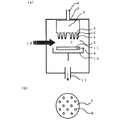
【図1】本発明のガス導入ノズルを備えた外熱式CVD反応炉の一例を示す概略図であり、(a)は炉断面図、(b)は流量制御室の底面図である。
【図2】本発明のガス導入ノズルにおけるガス導入孔近傍の拡大図である。
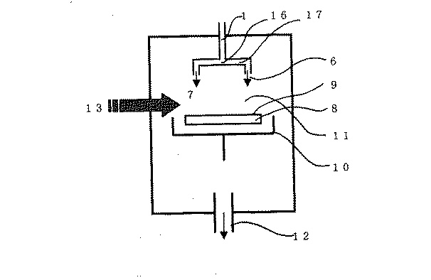
【図3】本発明に係わる、ガス複槽流量制御室導入孔構造を有する外熱式CVD反応炉の他の実施形態を示す概略図であり、(a)は炉断面図、(b)は流量制御室底面図である。
【図4】従来のガス導入ノズルを用いた外熱式CVD反応炉の一例を示す概略図である。
【図5】従来のガス導入ノズルを用いた外熱式CVD反応炉の一例を示す概略図である。
【図6】従来のガス導入ノズルを示す概略図であり、(a)は側面図、(b)は底面図である。
【図7】従来のガス導入ノズルを示す概略図であり、(a)は側面図、(b)は底面図である。
【符号の説明】
1、1’:ガス導入管
2、2’:流量制御室流入口
3、3’:流量制御室
4、4’:流量制御室流出口
5、5’:流量制御室以降の原料ガス導入管
6、6’:ガス導入孔
7、7’:導入孔以降のガス
8:基体
9:基体コート面
10:基体フォルダ
11:CVDチャンバー
12:排気系
13:エネルギー
14:流量制御室筐体
15:導入孔脱着構造部
16、16’:分岐部
17、17’:分岐部以降のガス導入管[0001]
TECHNICAL FIELD OF THE INVENTION
The present invention provides a gas introduction nozzle for a semiconductor manufacturing apparatus such as a thin film generation apparatus using a CVD method, wherein one or several kinds of gases serving as a raw material for chemical synthesis of a thin film, or raw material fine particles using a gas that does not contribute to a reaction as a carrier. The present invention relates to a gas introduction pipe for introducing into a chamber.
[0002]
[Prior art]
Conventionally, for example, as shown in FIG. 4, in a thin film forming apparatus by a CVD method, one or several kinds of gas as a raw material for chemical synthesis of a thin film, or raw material fine particles (hereinafter collectively referred to as a gas) that does not contribute to the reaction. The source gas 7 is introduced into the chamber 11 through a single pipe and a single source gas inlet 6 without branching the source gas 1, and a CVD reaction is performed. While applying the energy 13 to the substrate coating surface 9 on the substrate 8 held by the substrate folder 10, synthesizing a CVD thin film, and discharging the residue and carrier gas from the exhaust system 12 to the outside of the chamber 11. There were many pipe introduction hole structures. However, the single pipe introduction hole structure has a problem in that the thickness distribution of the synthesized thin film varies and biases.
[0003]
Therefore, a multiple pipe introduction hole structure having a plurality of source gas introduction pipes 17 and source gas introduction holes 6 as shown in FIG. 5 has also been proposed. The multi-pipe introduction hole structure is a pipe which aims to introduce the raw material gas 7 more evenly into the reaction tank 11 by branching the pipe 1 of one introduction pipe at a branch portion 16 from the middle. Road structure.
[0004]
[Problems to be solved by the invention]
However, in the multiple pipe introduction hole structure as shown in FIG. 5, the structure of the branch portion 16 of the source gas introduction pipe becomes complicated, and it becomes difficult to uniformly introduce the source gas 7 from each of the introduction pipes 17 after branching. For this reason, it was difficult to increase the number of source gas introduction holes 6. Therefore, there is a disadvantage that the number of the raw material gas introduction holes 6 with respect to the area of the substrate coating surface 9 is small, and the film thickness distribution of the thin film formed on the substrate 8 has uneven distribution of the film thickness corresponding to the number of the introduction holes 6. Was. Unless the structure of the branch portion 16 of the introduction pipe is made uniform and finished for all the introduction pipes 17, the specific energy loss of the source gas fluid at the time of branching into each introduction pipe is uniform. Therefore, there is a disadvantage that the flow rates branched to the respective introduction pipelines are not the same, a large amount of the raw material gas flows through the pipelines with low loss, and the film thickness is increased only in that direction.
[0005]
Further, when there are two or more types of raw material gas, not only the route of the pipe becomes complicated, but also it is extremely difficult to make the length and the pipe shape of the pipe after the branch portion the same. There was a problem that a large amount of the raw material gas flowed through a pipeline having a small flow rate. In other words, in the multiple pipe introduction hole structure, the gas outflow from each introduction hole will not be uniform unless the pipe loss after the branch portion is made uniform, so that each introduction hole is arranged concentrically as an ideal arrangement. , It is necessary to take a branch point at the center. However, when there are two or more types of source gases in a multiple pipe introduction hole structure, it is difficult to arrange all the branch portions at the centers of concentric circles of the respective introduction holes due to interference of the respective source gas pipelines. That is, as shown in FIG. 6, if all the introduction holes 6 for two or more types of source gas are arranged on the same concentric circle, the branch 16 of any of the source gas pipelines is eccentric and the pipes after the branch 16 are deviated. If the pipe length of the pipe 17 must be different, and the pipe diameter after branching is the same, the pipe resistance of the longer inlet pipe 17 increases, and the flow rate of the raw material gas is smaller than that of the shorter inlet pipe 17. Will be reduced. In order to avoid this, the diameter of the longer introduction pipe 17 should be larger than that of the shorter introduction pipe, and the increase in the pipe resistance due to the longer pipe and the larger pipe diameter. It is necessary to make the reduction of the pipeline resistance due to the same. However, even if the pipes are designed to have the same pipe loss in terms of fluid dynamics, it is actually very difficult to make the two losses the same due to a loss outside the calculation.
[0006]
Also, as shown in FIG. 7, if the lengths of all the pipelines after the branching section 16 are the same for each of the source gas introduction pipelines, the respective introduction holes of the respective source gas introduction pipelines are arranged on the same concentric circle. However, it is difficult to make the centers of the concentric circles the same from the viewpoint of complicated handling and increased pipe loss. Therefore, it is necessary to make one of the branch portions 16 an eccentric branch portion 16, and at this time, the thickness distribution of the generated CVD thin film on the base coat surface is biased. In particular, when the raw material gas is a corrosive gas, it is necessary to use a corrosion-resistant material for the introduction pipe, and it is difficult to manufacture a pipe that can uniformly introduce the raw material gas due to the difficulty of the processing.
[0007]
Further, in a plurality of source gas introduction holes 6 as shown in FIGS. 5, 6, and 7, the flow rate of the source gas from the source gas introduction holes 6 to the CVD chamber is increased, so that the source gas flows into the end of the introduction hole opening. In order to suppress the chemical reaction from the substrate to the substrate to be subjected to thin film CVD, and to cause a chemical reaction efficiently at the time when the raw material gas hits the substrate and the flow velocity in the flow direction of the introduction hole is reduced, the source gas introduction hole 6 is formed. When the diameter is reduced, the flow rates of the raw material gas 7 from the raw material gas introduction holes 6 are different from each other as described above. Therefore, even when the diameter is the same, the Reynolds number is lower than the critical Reynolds number under normal conditions. In some cases, some raw material gas introduction holes 6 exceeding about 2,320 and others not. If the critical Reynolds number is lower than the lower limit, the flow may become turbulent, and this causes a further unevenness in the thickness of the CVD-produced film.
[0008]
In addition, the state in which individual fluid particles move smoothly in a smooth line is called laminar flow, and the irregularly disturbed movement is called turbulent flow, but the flow in a certain pipe becomes laminar. The turbulence is determined by the Reynolds number Re = vd / ν derived from the inner diameter d of the pipe, the average flow velocity v in the pipe, and the kinematic viscosity ν of the fluid flowing through the pipe.
It is known to be determined by That is, if the Reynolds number Re is smaller than a certain value Rec, the flow becomes laminar, and if it is higher than Rec, the flow becomes turbulent. The value Rec of the Reynolds number that forms this boundary is called a critical Reynolds number. However, the critical Reynolds number when the flow velocity of the fluid gradually increases and the laminar flow replaces the turbulent flow, and the critical Reynolds number when the flow velocity of the fluid gradually decreases and the turbulent flow replaces the laminar flow There is a difference from the Reynolds number. The former is called the upper limit of the critical Reynolds number, and the latter is called the lower limit of the critical Reynolds number. When the Reynolds number is even lower than the lower limit of the critical Reynolds number, even if the flow of the fluid is intentionally disturbed into turbulence, it will naturally settle and the flow will become laminar. Under normal flow conditions, the lower limit of the critical Reynolds number is about 2,320.
[0009]
[Means for Solving the Problems]
According to the present invention, as a result of repeated studies from the viewpoint of fluid dynamics, a gas tank called a flow rate control chamber is provided in the gas introduction pipe in the middle of the pipe so that the static pressure of gas is highest in the pipe. Further, by providing a plurality of gas introduction holes in the partition wall between the flow control chamber and the chamber, the gas in a gas storage tank state, that is, a stagnation state with almost no flow in the flow control chamber is transferred from the plurality of gas introduction holes to the chamber. It can be introduced at a uniform flow rate, a uniform flow rate, or at an arbitrary flow rate and flow rate, respectively, and it is possible to reduce unevenness and variation in the film thickness distribution on the substrate-coated surface.
[0010]
In addition, by providing the flow control chamber structure in the middle of the pipe, the position of the gas inlet, which has complicated the arrangement of the gas pipe, can be freely arranged, and the gas introduction pipe can be complicated and the gas can be uniformly introduced.
[0011]
Further, with the above structure, it is possible to easily use a corrosion-resistant member such as carbon or ceramic which has been difficult to use in the case of a conventional pipe structure due to processing reasons, and to improve the corrosion resistance.
[0012]
Furthermore, by making a part or all of the openings of the plurality of gas introduction holes of the flow rate control chamber detachable, it is easy to remove the products that block the gas introduction holes or significantly increase the exit resistance of the introduction holes. In addition, part or all of the deteriorated gas introduction hole can be easily replaced.
[0013]
In addition, since the gas supply amount from the gas introduction hole becomes constant by the flow control chamber structure, the diameter of the plurality of gas introduction holes exceeds the critical Reynolds number lower limit of 2,320, which is the critical Reynolds number under normal conditions. In such a range, the outflow rate of the gas from the flow control chamber to the chamber is increased, and the chemical reaction from the gas to the target substrate from the end of the opening of the introduction hole is suppressed. When the flow velocity in the flow direction of the contact hole falls, a chemical reaction can be efficiently caused.
[0014]
BEST MODE FOR CARRYING OUT THE INVENTION
A CVD thin film forming apparatus will be described as an embodiment of the present invention.
[0015]
As shown in FIG. 1, in a thin film forming apparatus by a CVD method, raw material fine particles (hereinafter collectively referred to as raw material gas 7) using one or several kinds of gases as raw materials for chemical synthesis of a thin film or a gas not contributing to a reaction as a carrier. The source gas 7 is introduced into the chamber 11 through a source gas tank, which is provided in the middle of the source pipe 1 and is called a flow control chamber 3 as large as possible. While providing the substrate 13, it is guided to the substrate coat surface 9 on the substrate 8 held by the substrate folder 10, a CVD thin film is synthesized, and the residue and the carrier gas are discharged from the exhaust system 12 to the outside of the chamber 11.
[0016]
In the conventional single pipe introduction hole structure, there is a problem that the thickness distribution of the synthesized thin film is varied and biased. On the other hand, by providing a source gas tank called a flow control chamber 3 as large as possible as shown in FIG. 1 in the source gas introduction pipe, the source gas is supplied into the flow control chamber 3 by Bernoulli's theorem. , A stagnation state in which the flow velocity of the source gas is almost eliminated, and the source gas in the flow control chamber 3 exhibits the highest pressure in the pipeline. Further, by providing a plurality of source gas introduction pipes 5 and source gas introduction holes 6 in a partition wall between the flow control chamber 3 and the CVD chamber 11, the source gas in the gas storage state in the flow control chamber 3 is subjected to CVD. It can be introduced into the chamber 11 at a uniform flow rate and flow rate. In the gas storage tank state, the source gas exhibits a substantially uniform pressure on the inner wall surface of the flow rate control chamber 3 regardless of its location, so that the pressure loss in the source gas introduction pipes 5 and the source gas introduction holes 6 and The material, the surface roughness, the diameter, the pipe length of the inlet pipe 5, the pipe shape, and the connection between the flow rate control chamber 3 and the source gas inlet pipe 5 so that the outlet resistance becomes uniform. If the shape of the portion 4 and the shape of the opening of the material gas introduction hole 6 are made uniform, the material gas 7 can be introduced into the CVD chamber 11 at a substantially uniform flow rate and flow rate.
[0017]
At this time, if the flow rate control chamber 3 has a size such that the internal capacity is substantially in an air storage tank state, that is, an infinitely large size such that the flow rate of the raw material gas flowing into the flow rate control chamber 3 becomes zero, The position of the raw material gas inlet 2 to the flow control chamber 3 can be freely arranged. This is because the flow rate of the raw material gas flowing into the flow control chamber 3 becomes almost stagnation with almost no flow velocity, and the fluid propagates as a static pressure to the entire inner wall surface of the flow control chamber 3 instead of the flow velocity form according to Bernoulli's theorem. This is because the source gas is transmitted to each source gas introduction pipe 5 as a uniform pressure regardless of the distance from the source gas inlet 2. In other words, in the conventional multiple pipe introduction hole structure shown in FIGS. 5 to 7, the source gas introduction holes 6 are arranged concentrically for the purpose of making the length of the source gas introduction pipeline 17 after the branch portion 16 uniform. In this case, it is necessary to arrange the raw material gas introduction pipe 1 before the branch at the center of the concentric circle. On the other hand, in the flow control chamber structure of the present invention shown in FIG. 1, even if the raw material gas inlet 2 to the flow control chamber 3 is freely arranged, if the inside of the flow control chamber 3 is in an air storage tank state, It does not affect the flow rate and supply amount of the raw material gas 7 from the gas inlet 6.
[0018]
However, due to the size of the flow control chamber 3, it is almost impossible to make the inside of the flow control chamber 3 substantially in an air storage tank state, so that the resistance of the flow of the source gas from the flow control chamber 3 to the CVD chamber 11 is reduced. By increasing the pressure and increasing the pressure in the flow control chamber 3, it is possible to approach the state of the air storage tank. Considering this simply, assuming that the pressure in the chamber 11 is constant, the specific energy loss of the source gas introduction line 5 and the line loss of the source gas introduction hole 6 in the flow rate control chamber 3 is reduced by the source gas fluid. This is because, by increasing the total pressure loss multiplied by the density, the total pressure loss becomes the pressure increase in the flow control chamber 3 as it is.
[0019]
Here, the simplest method for increasing the pressure in the flow control chamber 3 is to reduce the diameter of the raw material gas introduction hole 6 to increase the flow velocity of the raw material gas 7 flowing out from the raw material gas introduction hole 6, The fourth object is to make the shape of the C-plane shape large in loss. Specifically, when the diameter of the source gas introduction hole is 1 / x, the flow rate of the source gas 7 flowing out is twice as large as x, and the total pressure loss is four times as large as x. That is, when the diameter of the raw material gas introduction hole is reduced to 1 /, the total pressure loss becomes 16 times.
[0020]
Further, by changing the shape of the connecting portion 4 from the R-shaped chamfer to the C-shaped chamfer, the total pressure loss becomes about 1.25 times.
[0021]
In addition, by reducing the diameter, the flow rate of the source gas 7 from when the source gas 7 flows out of the source gas introduction hole 6 to when the flow rate of the source gas 7 falls on the base coat surface 9 can be increased. As a result, the energy 13 applied to the source gas 7 during that time can be kept small and the CVD chemical reaction can be minimized, so that the source gas can be efficiently formed into a CVD thin film on the base coat surface 9. to be born.
[0022]
However, if the diameter of the raw material gas introduction hole 6 is too small, the flow of the raw material gas 7 at the time of outflow becomes turbulent, which affects the film thickness distribution on the base coat surface 9. Therefore, it is necessary to make the flow when the source gas 7 flows out into a laminar flow. For this purpose, the lower limit of the inlet hole diameter is such that the Reynolds number of the flow when the raw material gas 7 flows out of the raw material gas inlet hole does not exceed the critical Reynolds number lower limit value under normal conditions of about 2,320. There is.
[0023]
Furthermore, in the conventional multiple pipe introduction hole structure, the number of source gas introduction holes 6 is limited for structural reasons (usually, four introduction holes and a diameter of the introduction hole of 5 mmφ are used). When the diameter of the inlet hole is reduced in order to minimize the CVD chemical reaction between the time when the gas flows out of the raw material gas inlet hole 6 and the time when the flow rate falls and hits the base coat surface 9, the Reynolds number is critical under normal conditions. In order not to exceed the lower limit of Reynolds number of about 2,320, it was not possible to increase the supply amount of source gas per unit time. That is, it is necessary to sacrifice the total supply amount of the raw material gas to the flow rate control chamber, that is, the total amount of the raw material gas used for the CVD chemical reaction, by reducing the diameter of the introduction hole in order to increase the flow velocity of the raw material gas 7. . However, in the flow rate control chamber structure of the present invention, the number of the source gas introduction holes 6 can be almost freely increased, so that the flow rate of the source gas can be increased, and the supply amount of the source gas can be increased by increasing the number of the source gas introduction holes 6. The total amount of source gas used for the CVD chemical reaction can be increased accordingly. Thereby, it becomes easy to adjust the supply amount of the source gas, which is one of the parameters of the CVD chemical reaction.
[0024]
When a pump or the like is used as a means for generating the pressure for supplying the source gas, the pressure has a cycle of high and low pressures corresponding to the product of the number of rotations of the pump and the number of blades of the pump, that is, a pulsation. Since the state of the air storage tank functions as a cushion, there is also an advantage that pulsation when the raw material gas 7 flows out of the raw material gas introduction hole can be eliminated.
[0025]
Further, when the thin film coating surface 9 of the substrate to be CVD is positioned vertically with respect to the outflow direction of the source gas 7 from the source gas introduction hole 6, the source gas per unit area of the substrate coating surface 9 By disposing the raw material gas introduction holes 6 so that the supply amount of the CVD thin film is substantially uniform, the film thickness distribution of the CVD thin film on the base coat surface 9 can be made substantially uniform. Conversely, by designing the outlet loss and the arrangement of the source gas introduction holes 6 arbitrarily different depending on the place, the flow rate and flow rate of the source gas from each source gas introduction hole can be arbitrarily controlled, and There is also an advantage that the film thickness distribution can be arbitrarily controlled.
[0026]
Furthermore, when manufacturing a CVD apparatus, considering the difficulty of processing and cost, the parallelism of the source gas introduction direction of each source gas introduction pipe and the source gas introduction hole 6 is made uniform with the conventional multiple pipe introduction hole structure. Rather than performing such processing, it is more preferable to perform processing for uniforming the parallelism of the source gas introduction directions of the source gas introduction pipes 5 and the source gas introduction holes 6 in the flow rate control chamber structure as in the present invention. It is advantageous. This is because, in the case of the conventional multiple pipe introduction hole structure, the pipe is bent by the pipe bender and the pipe is routed by welding at the pipe branch portion 16, so that the processing accuracy is low, and the residual stress in the pipe itself is low. This is because, for example, it is damaged in a short time in a heat cycle for the CVD reaction.
[0027]
On the other hand, in the flow rate control chamber structure of the present invention, since most of the machining steps are completed in the mechanical cutting, the machining accuracy can be relatively high, and the structure can be strengthened, so that the life of the pipeline can be extended.
[0028]
Also, when the raw material gas is a corrosive gas, a corrosion-resistant material is used for the pipeline, but it is often difficult to weld a corrosion-resistant metal. The degree goes up. Accordingly, the flow rate control chamber structure of the present invention facilitates processing, so that the effect of equalizing the parallelism of the raw material gas outflow direction axis of each introduction hole is further improved. Further, in the flow control chamber structure of the present invention, it is easy to adopt carbon and ceramic. This is because carbon and ceramics require plastic processing such as cutting for their processing, so that it is difficult to process them into a pipe shape, but the processing is relatively easy with a flow rate control chamber structure.
[0029]
Further, as shown in FIG. 2, a joint 15 between the flow control chamber housing 14 constituting the flow control chamber wall surface and the raw material gas introduction pipe 5 has a fitting structure or a structure that can be detached by a screw structure or the like. The removal of the CVD product formed so as to close the inner diameter of the source gas introduction pipe 5 and the source gas introduction hole 6 or to significantly increase the exit resistance of the source gas introduction hole 6, and to reduce the deteriorated source gas. The introduction conduit 5 can be easily replaced from its joint 15.
[0030]
Further, when there are two or more types of raw material gases, a flow control chamber structure having a multiple tank flow control chamber having independent flow control chambers 3 and 3 'for each raw material gas as shown in FIG. It is possible to simplify the configuration of an apparatus that can freely arrange the positions of the raw material gas inlets 2 and 2 ′ to 3, 3 ′.
[0031]
Similarly, the flow rate control chamber having the structure shown in FIG. 3 can be introduced into the CVD chamber at a uniform flow rate and a uniform flow rate, or at an arbitrary flow rate and flow rate. Unevenness and variation can be reduced.
[0032]
Further, a corrosion-resistant member such as carbon or ceramic can be easily used, and a part or all of the openings of the plurality of source gas introduction holes can be configured to be detachable.
[0034]
【Example】
As an embodiment of the present invention, an externally heated CVD reactor having a double-tank flow rate control chamber structure of the present invention as shown in FIG. An AlN film was formed by a synthesis method. To form the AlN film, the AlN substrate was placed in a furnace heated to 950 ° C. by an external heating method, and a mixed gas of 8 SLM of nitrogen (SLM = Liter / min. At standard temperature) and 1 SLM of ammonia was supplied to a multi-tank flow control chamber. Through one of the flow control chambers 3 and the eight inlet holes 6 (φ5 mm), and through the other flow control chamber 3 and the twelve inlet holes 6 (φ5 mm) to reduce aluminum chloride to 0. The reaction was started at a pressure of 80 torr by flowing 0.3 SLM, and an AlN film having an average thickness of about 100 μm was formed by the reaction for 3 hours. The Reynolds number at this time was approximately irrespective of the length of the inlet diameter, Re = 226, and the total pressure loss in the gas inlet was 4.56 Pa.
[0035]
As a comparative example, using an externally-heated CVD reactor having a conventional multiple-pipe introduction hole structure as shown in FIG. In a heated furnace, a mixed gas of 8 SLM of nitrogen and 1 SLM of ammonia flows through the source gas introduction line 1 in which the source gas branch portion 16 is eccentric, and the center of the disk-shaped AlN substrate, the source gas line branch portion 16 and The reaction was started at a pressure of 80 torr by flowing 0.3 SLM of aluminum chloride through the raw material gas introduction pipe line 1 on the same raw gas outflow direction axis, and an AlN film was formed by the reaction for 3 hours.
[0036]
When the thickness variation of each AlN film was measured, the AlN film obtained by the film formation of the comparative example was placed on an AlN substrate corresponding to the downstream portion in the flow direction axis of the four introduction holes 6 of the aluminum chloride introduction conduit. Four places where the film thickness was unevenly distributed were formed. As shown in Table 1, the film thickness difference between the portion where the film thickness was unevenly distributed and the portion where the film thickness was the smallest was 42 to 76 μm in five times of film formation.
[0037]
On the other hand, in the AlN film of the example of the present invention, no thick and unevenly distributed portion was found on the AlN substrate downstream of the source gas introduction hole 6 in the flow direction axis. As shown in Table 1, the difference in film thickness from the thinnest portion was 18 to 31 μm after eight film formations. The number of times of film formation in Table 1 indicates the number of times of forming the AlN thin film under the above conditions. Further, the thickness difference range (μm) is the range of the number of film forming times of the thickness difference between the thickest and the thinnest film thickness, the average thickness difference (μm) is the average, and the thickness difference variance (μm 2 ) Represents its variance.
[0038]
[Table 1]
[0039]
From Table 1, it is considered that there is a difference in the average film thickness difference between the present invention and the comparative example. Therefore, a test for equal variance and a test for the difference between population means are performed and confirmed. Table 2 shows the results of the F-test (test of equal variance) with the significance level set to 5%, and Table 3 shows the results of the t-test (test with samples assuming that the variances are not equal) with the significance level of 5%. .
[0040]
[Table 2]
[0041]
From Table 2, F = 8.157> 7.847 is highly significant at the significance level of 1%, and it cannot be said that the variance is equal between the multi-pipe structure and the multi-chamber structure with the introduction hole structure. Therefore, a t-test (test using a sample assuming that the variances are not equal) with a significance level of 5% is performed in Table 3.
[0042]
[Table 3]
[0043]
From Table 3, t = 5.114> 2.571 indicates that the significance is significant at the significance level of 5%, and it can be determined that there is a difference between the population mean in the present invention and the comparative example. Therefore, when comparing the point estimation values of the population mean, the average thickness difference of the formed AlN thin film is 56.4 (by changing the introduction hole structure from the multiple pipe structure to the double tank flow control room structure of the present invention). μm) to 24.6 (μm), which is less than half.
[0044]
【The invention's effect】
According to the present invention, many effects as described below can be obtained.
[0045]
(1) By providing a flow control chamber and a plurality of gas introduction holes in the gas introduction pipe, gas can be introduced from the plurality of gas introduction holes into the chamber at a uniform flow rate and a uniform flow rate. Unevenness and variation in the film thickness distribution on the surface can be reduced, and the number of gas introduction holes can be almost freely increased, so that the gas supply amount can be easily adjusted.
[0046]
(2) Since a simple structure can be used, a corrosion-resistant member that requires cutting such as carbon or ceramic can be easily used.
[0047]
(3) By adopting a structure in which the gas introduction hole is detachable, it is easy to remove a product that blocks the introduction hole, and it is possible to easily replace a part or all of the deteriorated opening of the gas introduction hole.
[0048]
(4) By controlling the diameter of the plurality of gas introduction holes so that the Reynolds number does not exceed the critical Reynolds number lower limit of about 2,320, which is a normal condition, the reaction up to the target substrate can be performed. Thus, when the gas hits the substrate and the flow velocity in the flow direction of the introduction hole drops, the reaction can be efficiently caused, and the gas can be efficiently thinned on the substrate coating surface.
[Brief description of the drawings]
FIG. 1 is a schematic view showing an example of an external heating type CVD reactor provided with a gas introduction nozzle of the present invention, wherein (a) is a cross-sectional view of the furnace, and (b) is a bottom view of a flow control chamber.
FIG. 2 is an enlarged view near a gas introduction hole in a gas introduction nozzle of the present invention.
FIGS. 3A and 3B are schematic views showing another embodiment of an externally heated CVD reactor having a gas double-tank flow rate control chamber introduction hole structure according to the present invention, wherein FIG. 3A is a cross-sectional view of the furnace, and FIG. It is a flow control room bottom view.
FIG. 4 is a schematic view showing an example of an externally heated CVD reactor using a conventional gas introduction nozzle.
FIG. 5 is a schematic view showing an example of an externally heated CVD reactor using a conventional gas introduction nozzle.
6A and 6B are schematic diagrams showing a conventional gas introduction nozzle, wherein FIG. 6A is a side view and FIG. 6B is a bottom view.
7A and 7B are schematic views showing a conventional gas introduction nozzle, wherein FIG. 7A is a side view and FIG. 7B is a bottom view.
[Explanation of symbols]
1, 1 ': gas introduction pipe 2, 2': flow control chamber inlet 3, 3 ': flow control chamber 4, 4': flow control chamber outlet 5, 5 ': source gas introduction pipe after the flow control chamber 6, 6 ': gas introduction holes 7, 7': gas after the introduction holes 8: substrate 9: substrate coated surface 10: substrate folder 11: CVD chamber 12: exhaust system 13: energy 14: flow control chamber housing 15: Inlet / detachment structure 16, 16 ': Branch 17, 17': Gas inlet pipe after the branch