JP3572166B2 - Corrugated sheet folding equipment - Google Patents
Corrugated sheet folding equipment Download PDFInfo
- Publication number
- JP3572166B2 JP3572166B2 JP10498997A JP10498997A JP3572166B2 JP 3572166 B2 JP3572166 B2 JP 3572166B2 JP 10498997 A JP10498997 A JP 10498997A JP 10498997 A JP10498997 A JP 10498997A JP 3572166 B2 JP3572166 B2 JP 3572166B2
- Authority
- JP
- Japan
- Prior art keywords
- cardboard sheet
- folded
- sheet
- corrugated cardboard
- folding
- Prior art date
- Legal status (The legal status is an assumption and is not a legal conclusion. Google has not performed a legal analysis and makes no representation as to the accuracy of the status listed.)
- Expired - Fee Related
Links
Images


Description
【0001】
【発明の属する技術分野】
本発明は、段ボールシートに罫線加工を施した後、この罫線に沿って段ボールシートを折り曲げ、折り畳まれた状態の段ボールシートを形成する段ボールシート折り畳み装置に関する。
【0002】
【従来の技術】
従来から、段ボール製凾機には、印刷,罫線,スロッタ溝及び打ち抜き等の加工を施した後、罫線に沿って段ボールシートを折り曲げ、折り畳まれた状態の段ボールシートを形成する段ボールシート折り畳み装置が備えられている。
段ボールシート折り畳み装置は、図10に示すように、図示しないスロッタクリーザと、罫線Kに沿って段ボールシート1を折り曲げ、折り畳まれた状態の段ボールシート1を形成する段ボールシート折り曲げ加工部40とを備えて構成される。
【0003】
ここで、スロッタクリーザは、段ボールシート折り曲げ加工部40の上流側に配設され、段ボールシート1に搬送方向に沿って2条の罫線K,スロッタ溝S等の加工を施すものである。
このスロッタクリーザは、2組の上下一対の罫線ローラを搬送方向に直交する方向に並列に備えて構成される。ここで、上下一対の罫線ローラは、上側罫線ローラと下側罫線ローラとから構成され、下側罫線ローラには1条の凸部が形成されており、これらの上側罫線ローラと下側罫線ローラとの間に段ボールシート1が導入されて挟持され、段ボールシート1に罫線Kを入れる加工が施されるようになっている。
【0004】
なお、この罫線Kを入れる加工(罫線加工)が施されることにより、段ボールシート1は罫線Kにより仕切られることになり、そのシート中央部の両端部に折り曲げ片2a,2bが形成される。
段ボールシート折り曲げ加工部40は、図10に示すように、段ボールシート1を支持し、段ボールシート1の折り曲げ片(段ボールシートパネル)2a,2bを罫線Kに沿って折り曲げ、折り畳む際に定規として機能するシートガイド20a,20bと、これらのシートガイド20a,20bの上方に対向するように配設され、段ボールシート1を搬送する搬送用ベルト17a,17bと、これらのシートガイド20a,20b及び搬送用ベルト17a,17bの下側側方に配設され、段ボールシート1の折り曲げ片(段ボールシートパネル)2a,2bを案内しながら折り曲げる折り曲げバー21a,21bと、この折り曲げバー21a,21bの下流側に配設され、段ボールシート1の折り曲げ片2a,2bを案内しながら押し上げて折り畳む折り畳み用ベルト5a,5bとを備えて構成される。
【0005】
ここで、搬送用ベルト17a,17bは、搬送用ローラ17c,17dに巻回されており、これらの搬送用ローラ17c,17dにより回転駆動されるようになっている。
折り曲げバー21a,21bは、シート搬送方向に沿って、漸次高さ方向及び幅方向の位置が変わるように傾斜されて配設されており、段ボールシート1の折り曲げ片2a,2bを案内しながら、徐々に折り曲げるようになっている。
【0006】
また、折り畳み用ベルト5a,5bも、シート搬送方向に沿って、漸次高さ方向及び幅方向の位置が変わるように傾斜されて配設されており、段ボールシート1の折り曲げ片2a,2bを案内しながら、徐々に折り畳み、折り曲げ片2bをその端部に形成された糊付片6を介して折り曲げ片2aに貼り合わせるようになっている。
【0007】
なお、折り畳み用ベルト5a,5bにより段ボールシート1の折り曲げ片2a,2bが折り畳まれる際には、段ボールシート1の両側端部は図示しないサイドローラに摺接し、これらのサイドローラにより押圧されるようになっている。
なお、図10では、段ボールシート1の折り曲げ片2a,2bの折り畳まれていく状態を、順次、二点鎖線及び実線で示しており、図中の矢印は折り畳まれる方向を示している。
【0008】
そして、図10に示すように、スロッタクリーザで罫線K,スロッタ溝Sの加工を施された段ボールシート1は、その折り曲げ片2a,2bが水平になるような状態でシートガイド20a,20bと搬送用ベルト17a,17bとの間隙に導入され、搬送用ベルト17a,17bの搬送力(段ボールシートと搬送用ベルトとの間に生じる摩擦力)によって、順次、下流側へ移送される。この際、段ボールシート1の折り曲げ片2a,2bの上面が、折り曲げバー21a,21bに摺接しながら案内され、定規として機能するシートガイド20a,20bに沿って罫線Kの位置で折り曲げられる。
【0009】
このようにして折り曲げられた段ボールシート1の折り曲げ片2a,2bは、さらに、折り畳みベルト5a,5bに摺接しながら徐々に折り畳まれ、折り曲げ片2bがその端部に形成された糊付片6を介して折り曲げ片2aに貼り合わされ、図9に示すような折り畳まれた状態の段ボールシート1が形成される。なお、図9中、Kは罫線、Sはスロッタ溝である。
【0010】
なお、折り曲げ片2bがその端部に形成された糊付片6を介して折り曲げ片2aに貼り合わされると、糊付片6の両側方にスロッタ溝Sが形成される。
このようにして折り畳まれた段ボールシート1は、その下流側に移送され、積重される。
【0011】
【発明が解決しようとする課題】
しかしながら、このような従来の段ボールシート折り畳み装置では、段ボールシート1の罫線Kに沿って、定規として機能するシートガイド20a,20bの角部を当てた状態で、折り曲げバー21a,21b及び折り畳み用ベルト5a,5bにより、段ボールシート1の折り曲げ片2a,2bを水平状態から略180°折り畳むようにしているが、その折曲部では、図11(a)に示すように、段ボールシート1本体の下側のライナ22aとこのライナ22aと重ね合わせる折り曲げ片2bのライナ22bとがぶつかり合い、これらのライナ22,22bのうち、潰れにくい方のライナが潰れ易い方のライナを押し潰すことになる。
【0012】
つまり、段ボールシート1本体の下側のライナ22aの方が潰れ易い場合は、図11(b)に示すように、罫線Kの位置がライナ接合面よりも上側になり、逆に、折り曲げ片2bのライナ22bの方が潰れ易い場合は、図11(c)に示すように、罫線Kの位置がライナ接合面よりも下側になる。
この場合、段ボールシート1の横方向(図中、左右方向)の長さは、サイドローラ16,16により規制されるため、図11(b)に示すように、罫線Kの位置がライナ接合面よりも上側になる場合は、段ボールシート1の折り曲げ片2a,2bの糊付部の両端に形成されるスロッタ溝Sの隙間が、図中、Paで示すように広くなってしまい、逆に、図11(c)に示すように、罫線Kの位置がライナ接合面よりも下側になる場合は、段ボールシート1の折り曲げ片2a,2bの糊付部の両端に形成されるスロッタ溝Sの隙間が、図中、Pbで示すように狭くなってしまう。
【0013】
このようにスロッタ溝Sの隙間が広くなったり、狭くなったりする場合、折り曲げ片2bの端部に形成された糊付片6の重なる部分も大きくなったり、小さくなったりするため、段ボールシート1を箱型化した場合にいびつになったり、その強度が著しく低下することになり、さらに、見映えも悪くなる。
また、罫線Kの位置がライナ接合面よりも上側になったり、下側になったりすると、段ボールシート1の折曲部が曲線になってしまうこともあり、これによっても、段ボールシート1を箱型化した場合の強度が低下し、その品質が著しく低下することになる。
【0014】
このような段ボールシート1の折曲部の精度不良に対処すべく、図示しないスロッタクリーザにおける罫線加工において、より強い押圧力により段ボールシート1を押し潰して罫線加工を行なうことが考えられるが、このように強い押圧力により段ボールシート1を押し潰すと、ライナの破れ(罫割れ)等が生じてしまうため好ましくない。
【0015】
また、折り曲げ片2a,2bの折り畳み(図9参照)や、折り曲げ片2bの糊付片6と折り曲げ片2aとの貼り合わせは、段ボールシート1を搬送用ベルト17a,17bにより搬送しながら行なわれるので、折り曲げ片2aと折り曲げ片2bとの貼り合わせが確実に行なえず、図12に示すように、折り畳まれた状態の段ボールシート1の上側部分と下側部分とが搬送方向に対して前後にズレて貼り合わされてしまうこともあり、その品質を著しく低下させるという課題もある。
【0016】
本発明は、このような課題に鑑み創案されたもので、段ボールシートの折り畳み精度を向上させて、段ボールシートを箱型化した段ボール箱の品質を向上させるようにした、段ボールシート折り畳み装置を提供することを目的とする。
【0017】
【課題を解決するための手段】
このため、請求項1記載の本発明の段ボールシート折り畳み装置は、罫線加工を施された段ボールシートを搬送しながら罫線に沿って該段ボールシートの両側部に形成された折り曲げ片をそれぞれ折り畳み状態とする段ボールシート折り畳み装置において、上記の各折り曲げ片を折り曲げて折り畳む折り曲げ加工手段と、上記の各折り曲げ片を折り畳まれた状態の該段ボールシートの両側部に当接するサイドローラと、該折り曲げ加工手段により折り畳まれる上記の各折り曲げ片を案内するシート案内手段とをそなえ、該シート案内手段が、上記の折り畳まれた状態の各折り曲げ片の端部が当接するように配設されていることを特徴としている。
【0018】
請求項2記載の本発明の段ボールシート折り畳み装置は、請求項1記載の装置において、上記の折り畳み状態の段ボールシートを搬送する係合部を有するシート搬送手段を備え、該係合部が、該折り畳み状態の段ボールシートの後端部に係合するように速度制御されることを特徴としている。
請求項3記載の本発明の段ボールシート折り畳み装置は、請求項1又は2記載の装置において、一対の罫線ロールを有し、該罫線ロールにより該段ボールシートに該罫線加工を施すスロッタクリーザを備え、該スロッタクリーザの該1対の罫線ロールのうちの少なくとも一方の罫線ロールは、該罫線用の凸部を複数条そなえていることを特徴としている。
【0019】
【発明の実施形態】
以下、図面により、本発明の実施の形態について説明する。
図1〜図8は本発明の一実施形態にかかる段ボールシート折り畳み装置を示すものである。
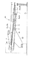
本実施形態の段ボールシート折り畳み装置は、段ボール製凾機に設けられ、図示しないスロッタクリーザと、図1に示すように、罫線Kに沿って段ボールシート1を折り曲げ、折り畳まれた状態の段ボールシート1を形成する段ボールシート折り曲げ加工部40とを備えて構成される。
【0020】
ここで、スロッタクリーザは、段ボールシート折り曲げ加工部40の上流側に配設され、段ボールシート1に搬送方向に沿って罫線K,スロッタ溝S等の加工を施すものである。
このスロッタクリーザは、シート横幅方向に並設された2組の上下一対の罫線ローラを備えて構成される。ここで、上下一対の罫線ローラは、図8に示すように、上側罫線ローラ19aと下側罫線ローラ19bとから構成され、下側罫線ローラ19bの外周面には複数条(ここでは、2条)の凸部19c,19cが形成されており、これらの上側罫線ローラ19aと下側罫線ローラ19bとの間に段ボールシート1が導入されて挟持され、段ボールシート1の折り曲げ箇所にそれぞれ複数条(ここでは、2条)の罫線Kを入れる加工(罫線加工)が施されるようになっている。
【0021】
なお、この罫線加工が施されることにより、段ボールシート1が罫線Kにより仕切られて、その両端部に折り曲げ片2a,2bが形成される。
段ボールシート折り曲げ加工部40は、図1に示すように、搬送用ベルト17a,17bと、折り曲げバー(折り曲げ手段)21a,21bと、折り畳み用ベルト(折り曲げ手段)5a,5bと、サイドローラ16,16と、シート貼合部ガイド(シート案内手段)3と、シート搬送装置(シート搬送手段)4とを備えて構成される。
【0022】
ここで、搬送用ベルト17a,17bは、段ボールシート1の上側面に当接して段ボールシート1を搬送するものである。
折り曲げバー21a,21bは、搬送用ベルト17a,17bの下側側方に配設され、段ボールシート1の折り曲げ片(段ボールシートパネル)2a,2bを案内しながら折り曲げるものである。
【0023】
これらの折り曲げバー21a,21bは、シート搬送方向に沿って、漸次高さ方向及び幅方向の位置が変わるように傾斜させて配設されており、段ボールシート1の折り曲げ片2a,2bを案内しながら、徐々に折り曲げるように構成されている。
折り畳み用ベルト5a,5bは、折り曲げバー21a,21bの下流側に配設され、段ボールシート1の折り曲げ片2a,2bを案内しながら押し上げるようにして折り畳むものである。
【0024】
これらの折り畳み用ベルト5a,5bも、シート搬送方向に沿って、漸次高さ方向及び幅方向の位置が変わるように傾斜させて配設されており、段ボールシート1の折り曲げ片2a,2bを案内しながら、徐々に折り畳むように構成されている。
サイドローラ16,16は、これらの折り畳み用ベルト5a,5bにより折り曲げ片2a,2bを折り畳む際に、段ボールシート1の両側端部に摺接しながら押圧するものである。
【0025】
シート貼合部ガイド3は、段ボールシート1の折り曲げ片2a,2bを案内するものである。
シート搬送装置(シート搬送手段)4は、シート貼合ガイド3の下流側上方に配設され、折り畳まれた状態の段ボールシート1を搬送するものである。
なお、図1中、30は幅方向移動フレームである。また、図1中の矢印は搬送方向を示しており、段ボールシート1はシートパスライン上を搬送する。
【0026】
また、従来の段ボールシート折り畳み装置と同様に、本段ボールシート折り畳み装置においても、段ボールシート1を支持し、段ボールシート1の折り曲げ片(段ボールシートパネル)2a,2bを罫線Kに沿って折り曲げ、折り畳む際に定規として機能するシートガイド20a,20b(図10参照)も備えられている。シートガイド20a,20bは、搬送用ベルト17a,17bの下方に対向するように配設されている。
【0027】
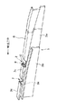
次に、本実施形態において特徴となるシート貼合部ガイド3について、図2〜図4を参照しながら説明する。
本シート貼合部ガイド3は、折り畳み用ベルト5a,5bにより段ボールシート1の折り曲げ片2a,2bを折り畳む工程及び段ボールシート1の折り曲げ片2a,2bの端部を貼り合わせる初期の工程において、段ボールシート1の折り曲げ片2a,2bを徐々に折り畳む際にこれらの折り曲げ片2a,2bを案内するものである。
【0028】
このシート貼合部ガイド3は、図2の一部破断した模式的斜視図に示すように、折り畳み用ベルト5bにより折り畳まれる段ボールシート1の一方の折り曲げ片2bを案内する本体部3aと、この本体部3aの上方に一体に設けられ、折り畳まれる折り曲げ片2bが上方へ逃げないように所定の高さ位置に保持するストッパ部8と、ストッパ部8の下流側に一体に形成されたガイドプレート部3cと、本体部3aの側面に固着され、段ボールシート1の他方の折り曲げ片2aを案内するL形案内部3bとを備えて構成される。なお、図2中、Zは破断部分である。
【0029】
ここで、本体部3aは、その上端部に、折り畳み用ベルト5bにより折り畳まれる折り曲げ片2bの端部が干渉しないように、折り曲げ片2bの折り曲げ状態に応じて徐々に上方位置になるように傾斜させて形成されたL形段差部3dを備え、このL形段差部3dとストッパ部8とにより、折り曲げ片2bを案内する溝9が形成されている。
【0030】
また、本体部3aのL形段差部3dには、溝9の内側に突出するように突起10が形成されており、この突起10により折り曲げ片2bが支持され、糊7を供給された折り曲げ片2bの糊付片6が本体部3aのL形段差部3dに接触しないで案内されるようになっている。
ガイドプレート部3cには、本体部3aに形成された突起10に支持される一方の折り曲げ片2bの水平方向へのズレを規制できるように段差部3eが形成されている。
【0031】
このように構成されるシート貼合部ガイド3は、折り曲げ片2a,2bが折り畳まれた状態で、折り曲げ片2a,2bのそれぞれの端部が当接するような位置に配設されており〔図4(d)参照〕、折り曲げ片2a,2bの折り畳み時に生じる水平方向へのズレを規制するようになっている。つまり、折り曲げ片2bの端部は、折り畳み時に溝9を構成するL形段差部3dの側面に当接し、折り畳み時に生じる水平方向へのズレが生じないようになっており、また、折り曲げ片2aの端部は、折り畳み時に本体部3aの側面に当接し、折り畳み時に生じる水平方向へのズレが生じないようになっている。
【0032】
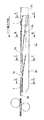
そして、段ボールシート1は、図3の模式的側面図において一点鎖線で示すように、その折り曲げ片2aが、徐々に折り曲げられて、折り畳まれた状態の段ボールシート1が形成され、その下流側に移送される。
つまり、シート貼合部ガイド3の図3のA−A矢視部では、図4(a)に示すように、段ボールシート1は搬送ベルト17により搬送されながら、その一方の折り曲げ片2bが、他方の折り曲げ片2aよりも一方の折り曲げ片2bの折曲角度θの方が先に小さくなるように他方の折り曲げ片2aに先行して、折り畳み用ベルト5bにより折り畳まれる。なお、折り曲げ片2aは折り畳み用ベルト5bにより折り畳まれる。
【0033】
この場合、シート貼合部ガイド3の上方には、溝9が形成されているため、折り曲げ片2bは本体部3aに干渉することなく折り畳まれることになる。なお、図4(a)中、符号13はフレームである。
次に、シート貼合部ガイド3の図3のB−B矢視部では、図4(b)に示すように、段ボールシート1の一方の折り曲げ片2bの端部は、折り畳み用ベルト5bにより折り畳まれながら、折り曲げ片2bの折り畳み状態に応じて徐々に上方位置になるように設けられた本体部3aのL形段差部3dに沿って本体部3aの上方に案内され、本体部3aのL形段差部3dとストッパ部8とにより形成された溝9内に収容される。
【0034】
この場合、折り曲げ片2bの端部は本体部3aの側面に当接し、折り曲げ片2bの折り畳み時に水平方向へのズレが生じることなく、正確に折り畳まれる。また、折り曲げ片2bは、糊7を塗布された糊付片6が本体部3aに接触しないように、本体部3aに形成された突起10に支持される。
次に、シート貼合部ガイド3の図3のC−C矢視部では、図4(c)に示すように、折り畳み用ベルト5bにより折り畳まれた段ボールシート1の一方の折り曲げ片2bは、その端部をストッパ部8と突起10との間に挟持される。一方、段ボールシート1の他方の折り曲げ片2aは、L形案内部3bの上面に沿うように案内されて、折り畳み用ベルト5aにより折り畳まれる。
【0035】
この場合、折り畳まれる段ボールシート1の両側部は、サイドローラ16,16により押圧され、折り畳まれる段ボールシート1の水平方向へのズレが生じないように規制される。また、一方の折り曲げ片2bの端部は、本体部3aのL形段差部3dの側面に当接し、折り曲げ片2bの折り畳み時に水平方向にズレを生じさせることなく、正確に折り畳まれる。
【0036】
次に、シート貼合部ガイド3の図3のD−D矢視部では、図4(d)に示すように、一方の折り曲げ加工部2bは、ガイドプレート3cと本体部3aの上端部との間に挟持される一方、他方の折り曲げ加工部2aは、折り曲げ加工部2aの折り畳み状態に応じて徐々に上方位置になるように設けられた案内部3bにより本体部3aの上方に案内され、本体部3aの上端部に設けられたガイドプレート3cの段差部3eに当接し、ガイドプレート3cと案内部3bとの間に挟持される。
【0037】
この場合、一方の折り曲げ片2bの端部は、ガイドプレート部3cに形成された段差部3eに当接し、折り曲げ片2bの折り畳み時に水平方向にズレを生じさせることなく、正確に折り畳まれた状態で、他方の折り曲げ片2aの端部が、本体部3aの側面に当接し、折り曲げ片2aの折り畳み時に水平方向にズレを生じさせることなく、正確に折り畳まれて、一方の折り曲げ片2bの糊付片6と他方の折り曲げ片2aの端部との重なり状態(重なり寸法)が正確に調整されて貼り合わされる。これにより、折り曲げ片2a,2bの折り畳み時の貼り合わせ精度を向上させることができる。
【0038】
次に、本実施形態において特徴となるシート搬送装置4について、図5〜図7を参照しながら説明する。
このシート搬送装置4は、本段ボールシート折り畳み装置の下流側であって、シートパスラインの上方に配設され、折り畳まれた状態の段ボールシート1の搬送を補助するものである。
【0039】
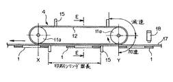
このシート搬送装置4は、図5の模式的断面図に示すように、シート横幅方向に並設された2組のタイミングベルト12,12を備え、これらのタイミングベルト12,12はそれぞれシンクロプーリ11a,11bに巻回されて構成されている。
これらのタイミングベルト12,12には、図5及び図6に示すように、その外周面に、前工程の印刷シリンダの周長に相当するピッチ(間隔)で、複数の爪部(係合部)15が固着されている。そして、タイミングベルト12,12に固着された爪部15が、折り畳まれた状態の段ボールシート1の後端部に係合し、折り畳まれた状態の段ボールシート1の上側部分と下側部分とがズレないようにして、段ボールシート1を搬送するようになっている。
【0040】
また、シンクロプーリ11a,11bは、それぞれフレーム13,13へ軸受を介して軸支されており、それぞれサーボモータ14,14により駆動されるようになっており、2組のタイミングベルト12,12は、同期して走行するようになっている。
これらのタイミングベルト12,12は、図6及び図7に示すように、タイミングベルト12,12に固着された爪部15が段ボールシート1に係合する直前の位置で、一旦減速した後、光電管18による段ボールシート1の後端部の検知信号をフィードバックしてサーボモータ14を駆動して加速させ、タイミングベルト12の外周面へ固着した爪部15を、搬送される段ボールシート1の後端へ追いつかせて係合させ、係合させた後は所定時間同速度(図7参照)で段ボールシート1を搬送するようになっている。このような速度制御は、段ボールシート1が搬入される毎に繰り返し行なわれる。
【0041】
具体的には、タイミングベルト12,12に固着された爪部15の速度は、図7の速度線図に示すように、タイミングベルト12,12の各位置X,Y,Oで、一旦遅くなった後、速くなるように制御され、その他の位置では、搬送ベルトの速度よりも速くなるように制御されるようになっている。
なお、タイミングベルト12の爪部15のタイミングを段ボールシート1の後端部に合わせるため、タイミングベルト12,12が巻回されている上流側のシンクロプーリ11aの回転軸と下流側のシンクロプーリ11aの回転軸との距離(図6参照)は、前工程の印刷シリンダ周長の整数倍に設定している。
【0042】
本実施形態の段ボールシート折り畳み装置は、上述のように構成されるため、以下に示すように動作する。
つまり、図1に示すように、図示しないスロッタクリーザで罫線K,スロッタ溝Sの加工を施された段ボールシート1は、その折り曲げ片2a,2bが水平になるような状態で、シートガイド20a,20bと搬送用ベルト17a,17bとの間隙に導入され、搬送用ベルト17a,17bの搬送力(段ボールシートと搬送用ベルトとの間に生じる摩擦力)によって、順次、下流側へ移送される。この際、段ボールシート1の折り曲げ片2a,2bの上面が、折り曲げバー21a,21bに摺接しながら、図示しない定規として機能するシートガイド20a,20bに沿って罫線Kの位置で折り曲げられる。
【0043】
このようにして折り曲げられた段ボールシート1の折り曲げ片2a,2bは、さらに、折り畳み用ベルト5a,5bに摺接しながら徐々に折り畳まれて、折り畳まれた状態の段ボールシート1が形成される。
このように段ボールシート1が搬送される際に、図4(a)〜(d)に示すように、段ボールシート1の折り曲げ片2bは、シート貼合部ガイド3の本体部3aのL形段差部3dに沿って案内され、L形段差部3dの側面に当接して折り畳み時の水平方向へのズレが生じないような状態で、折り畳みベルト5bにより正確に折り畳まれた状態で、段ボールシート1の折り曲げ片2bがシート貼合部ガイド3のL形案内部3bに沿って案内され、本体部3aの側面に当接して折り畳み時の水平方向へのズレが生じないような状態で、折り畳みベルト5aにより正確に折り畳まれ、折り曲げ片2bの糊付片6と折り曲げ片2aの端部との重なり状態(重なり寸法)が正確に調整されて貼り合わされる。
【0044】
そして、折り畳まれた状態の段ボールシート1は、その後端部が、下流側に配設されたシート搬送装置4のタイミングベルト12,12に固着された爪部15に係合して搬送される。このため、その上側部分と下側部分とにズレが生じることがなく、段ボールシート1を箱型化した場合の平行及び直角部の精度を維持することができることになる。
【0045】
その後、このようにして折り畳まれた段ボールシート1は、その下流側の後工程に移送され、積重される。
したがって、本実施形態の段ボールシート折り畳み装置によれば、段ボールシート1を折り畳む際に、サイドローラ16,16により段ボールシート1の水平方向へのズレが生じないように規制された状態で、シート貼合部ガイド3により段ボールシート1の折り曲げ片2a,2bの折り畳み時に生じる水平方向へのズレが生じないように規制されるため、段ボールシート1の折曲部での罫線Kの位置が、ライナ接合面よりも上方になったり、下方になったり、さらには曲線になったりすることがなく、折り曲げ片2bの糊付片6と折り曲げ片2aとの重なり状態(重なり寸法)にズレが生じないようにし、貼合部のスリット溝Sの幅が正確に形成できるようになり、折り曲げ片2b,2aの折り畳み精度を向上させることができ、正確な寸法,形状を有する高品質の段ボール箱を形成できるという利点がある。
【0046】
また、段ボールシート1の折り目が、直線的に、かつ確実に形成できるため段ボール箱の強度を大幅に向上させることができるため、その用途によっては、薄いライナや質の悪い原紙に変更することもでき、省資源化や製造原価の低減を図ることができる。また、段ボール箱の成形時の見映えが良くなり製品の美的品質が向上する。
【0047】
また、折り畳まれた状態の段ボールシート1は、シート搬送手段4のタイミングベルト12に固着された爪部15は、段ボールシート1の後端部に係合するように速度制御され、折り畳まれた状態の段ボールシート1が、このように速度制御されるシート搬送手段4のタイミングベルト12に固着された爪部15に係合することにより搬送されるため、段ボールシート1の上側部分と下側部分とが搬送方向に対して前後にズレが生じるおそれがなく、折り曲げ片2bの糊付片6と折り曲げ片2aとを正確な位置で、確実に貼り合わせることができ、段ボール箱の組立時の歪みをなくすことができるという利点もある。
【0048】
また、本実施形態の段ボールシート折り畳み装置では、スロッタクリーザの下側罫線ローラ19bの外周面に、複数条(ここでは、2条)の凸部19c,19cが形成されており、段ボールシート1の折り曲げ箇所にそれぞれ複数条(ここでは、2条)の罫線Kを入れる加工が施されるようになっているため、段ボールシート1の折り曲げ片2a,2bを折り曲げて折り畳む際の折り目位置に罫線幅方向の融通性ができ、段ボールシート1の折り畳み寸法の精度をより向上させることができるという利点がある。
【0049】
なお、本実施形態の段ボールシート折り畳み装置では、シート搬送装置4をシートパスラインの上方に設けているが、シートパスラインの下方に設けてもよい。
また、本実施形態の段ボールシート折り畳み装置では、シート搬送装置4の係合部を爪部15として構成しているが、これに限られるものではなく、折り畳まれた状態の段ボールシート1に係合しうるものであればよい。
【0050】
さらに、本実施形態の段ボールシート折り畳み装置では、シート搬送装置4の速度を一旦減速させた後に加速して、シート搬送装置4の爪部15が折り畳まれた状態の段ボールシート1の後端部に係合するようにしているが、シート搬送装置4の速度制御は、これに限られるものではなく、シート搬送装置4の爪部15が折り畳まれた状態の段ボールシート1の後端部に係合させることができるのであればよい。
【0051】
また、本実施形態の段ボールシート折り畳み装置では、シート貼合部ガイド3,シート搬送装置4を備えるものとして構成し、さらに、スロッタクリーザの罫線ロールを複数条の凸部を有するものとして構成しているが、例えば、シート貼合部ガイド3のみを備えるものとして構成し、スロッタクリーザの罫線ロールを1条の凸部を有するものとして構成しても良いし、また、シート貼合部ガイド3,シート搬送装置4を備えるものとして構成し、スロッタクリーザの罫線ロールを1条の凸部を有するものとして構成しても良い。
【0052】
【発明の効果】
以上詳述したように、請求項1記載の本発明の段ボールシート折り畳み装置によれば、段ボールシートを折り畳む際に、サイドローラにより段ボールシートの水平方向へのズレが生じないように規制されるとともに、シート案内手段により段ボールシートの折り曲げ片の折り畳み時に生じる水平方向へのズレが生じないように規制され、折り曲げ片の折り畳み精度を向上させることができ、これにより、一方の折り曲げ片と他方の折り曲げ片とを正確に貼り合わせ、貼合部のスリット溝の幅を正確に形成できるようになるため、正確な寸法,形状を有する高品質の段ボール箱を形成できるという利点がある。
【0053】
請求項2記載の本発明の段ボールシート折り畳み装置によれば、シート搬送手段の係合部は、段ボールシートの後端部に係合するように速度制御され、折り畳まれた状態の段ボールシートが、このように速度制御されるシート搬送手段の係合部に係合することにより搬送されるため、段ボールシートの上側部分と下側部分とが搬送方向に対して前後にズレが生じるおそれがなく、一方の折り曲げ片と他方の折り曲げ片とを正確な位置で、確実に貼り合わせることができ、段ボール箱の組立時の歪みをなくすことができるという利点がある。
【0054】
請求項3記載の本発明の段ボールシート折り畳み装置によれば、スロッタクリーザの罫線ローラの外周面に、複数条の凸部が形成されており、これらの複数条の凸部により、段ボールシートに複数条の罫線加工が施されるため、段ボールシートの折り曲げ片を折り曲げ、折り畳む際の折り目位置に罫線幅方向の融通性ができ、段ボールシートの折り畳み精度をより向上させることができ、これにより、より高品質の段ボール箱を形成できるという利点がある。
【図面の簡単な説明】
【図1】本発明の一実施形態にかかる段ボールシート折り畳み装置の全体構成を示す模式的側面図である。
【図2】本発明の一実施形態にかかる段ボールシート折り畳み装置のシート貼合部ガイドを示す模式的斜視図である。
【図3】本発明の一実施形態にかかる段ボールシート折り畳み装置のシート貼合部ガイドを示す模式的側面図である。
【図4】本発明の一実施形態にかかる段ボールシート折り畳み装置のシート貼合部ガイドを示す模式図であり、(a)は図3のA−A矢視断面図、(b)は図3のB−B矢視断面図、(c)は図3のC−C矢視断面図、(d)は図3のD−D矢視断面図である。
【図5】本発明の一実施形態にかかる段ボールシート折り畳み装置のシート搬送装置を示す模式的断面図である。
【図6】本発明の一実施形態にかかる段ボールシート折り畳み装置のシート搬送装置を示す模式的側面図である。
【図7】本発明の一実施形態にかかる段ボールシート折り畳み装置のシート搬送装置の速度線図である。
【図8】本発明の一実施形態にかかる段ボールシート折り畳み装置の前工程におけるスロッタクリーザを示す模式的断面図である。
【図9】折り畳まれた状態の段ボールシートを示す模式的斜視図である。
【図10】従来の段ボールシート折り畳み装置を示す模式的断面図である。
【図11】従来の段ボールシート折り畳み装置における段ボールシートを折り畳む際の課題を説明するための図であり、(a)は折り畳まれる際の段ボールシートの模式的断面図、(b)は罫線部分がライナ接合面よりも上がった状態を示す模式的断面図、(c)は罫線部分がライナ接合面よりも下がった状態を示す模式的断面図である。
【図12】従来の段ボールシート折り畳み装置における折り畳まれた状態の段ボールシートを搬送する際の課題を説明するための模式図である。
【符号の説明】
1 段ボールシート
2a,2b 折り曲げ片(段ボールシートパネル)
3 シート貼合部ガイド(シート案内手段)
3a 本体部
3b L形案内部
3c ガイドプレート部
3d L形段差部
3e 段差部
4 シート搬送装置(シート搬送手段)
5a,5b 折り畳み用ベルト(折り曲げ手段)
6 糊付片
7 糊
8 ストッパ部
9 案内溝
10 突起
11a,11b シンクロプーリ
12 タイミングベルト
13 フレーム
14 サーボモータ
15 爪部
16 サイドローラ
17a,17b 搬送ベルト
17c,17d 搬送用ローラ
18 光電管
19 罫線ロール
19a 上側罫線ロール
19b 下側罫線ロール
19c 凸部
20a,20b シートガイド
21a,21b 折り曲げバー(折り曲げ手段)
22 ライナ
30 幅方向移動フレーム
40 段ボールシート折り曲げ加工部[0001]
TECHNICAL FIELD OF THE INVENTION
The present invention relates to a corrugated cardboard sheet folding apparatus that forms a folded corrugated cardboard sheet after subjecting the corrugated cardboard sheet to crease processing, and then folding the corrugated cardboard sheet along the crease lines.
[0002]
[Prior art]
2. Description of the Related Art Conventionally, a corrugated cardboard box folding machine has been provided with a corrugated cardboard sheet folding device that performs processes such as printing, crease lines, slotter grooves and punching, and then folds the corrugated cardboard sheets along the crease lines to form a folded corrugated cardboard sheet. Provided.
As shown in FIG. 10, the corrugated cardboard sheet folding device includes a slotter creaser (not shown) and a corrugated cardboard
[0003]
Here, the slotter cleaner is disposed on the upstream side of the corrugated cardboard
This slotter cleaner is provided with two pairs of upper and lower ruled line rollers arranged in parallel in a direction orthogonal to the transport direction. Here, the pair of upper and lower ruled rollers are composed of an upper ruled roller and a lower ruled roller, and the lower ruled roller is formed with one convex portion. The
[0004]
By performing the process of inserting the ruled line K (ruled line processing), the
As shown in FIG. 10, the corrugated cardboard
[0005]
Here, the
The
[0006]
Further, the
[0007]
When the folded
In FIG. 10, the state in which the folded
[0008]
Then, as shown in FIG. 10, the
[0009]
The folded
[0010]
When the
The
[0011]
[Problems to be solved by the invention]
However, in such a conventional corrugated cardboard sheet folding apparatus, the
[0012]
In other words, when the liner 22a on the lower side of the
In this case, the length of the
[0013]
When the gap of the slotter groove S is widened or narrowed in this way, the overlapping portion of the glued
Also, if the position of the ruled line K is above or below the liner joint surface, the bent portion of the
[0014]
In order to cope with such inaccuracy of the bent portion of the
[0015]
The folding of the folded
[0016]
The present invention has been made in view of such problems, and provides a cardboard sheet folding apparatus that improves the folding accuracy of a cardboard sheet and improves the quality of a cardboard box in which a cardboard sheet is formed into a box. The purpose is to do.
[0017]
[Means for Solving the Problems]
For this reason, the corrugated cardboard sheet folding device of the present invention according to
[0018]
According to a second aspect of the present invention, there is provided a cardboard sheet folding apparatus according to the first aspect, further comprising a sheet conveying means having an engaging portion for conveying the folded corrugated cardboard sheet, wherein the engaging portion is The speed is controlled so as to engage with the rear end of the folded cardboard sheet.
The corrugated cardboard sheet folding device of the present invention according to
[0019]
DETAILED DESCRIPTION OF THE INVENTION
Hereinafter, embodiments of the present invention will be described with reference to the drawings.
1 to 8 show a cardboard sheet folding apparatus according to an embodiment of the present invention.
The cardboard sheet folding apparatus of the present embodiment is provided in a cardboard box machine, and a
[0020]
Here, the slotter cleaner is disposed on the upstream side of the corrugated cardboard
This slotter cleaner includes two pairs of upper and lower ruled rollers arranged side by side in the sheet width direction. Here, as shown in FIG. 8, the pair of upper and lower ruled line rollers includes an upper ruled line roller 19a and a lower ruled
[0021]
By applying the ruled line processing, the
As shown in FIG. 1, the corrugated cardboard
[0022]
Here, the
The bending bars 21a, 21b are disposed below the
[0023]
These bending bars 21a and 21b are arranged so as to be inclined so that the positions in the height direction and the width direction gradually change along the sheet conveyance direction, and guide the
The
[0024]
These
The
[0025]
The sheet
The sheet conveying device (sheet conveying means) 4 is disposed above the downstream side of the
In addition, in FIG. 1, 30 is a width direction moving frame. The arrow in FIG. 1 indicates the transport direction, and the
[0026]
Further, similarly to the conventional corrugated cardboard sheet folding apparatus, the corrugated cardboard sheet folding apparatus also supports the
[0027]
Next, the sheet
The sheet
[0028]
As shown in a partially broken schematic perspective view of FIG. 2, the sheet
[0029]
Here, the main body 3a is inclined at the upper end so that the end of the folded
[0030]
Further, a
The
[0031]
The sheet
[0032]
As shown by the dashed line in the schematic side view of FIG. 3, the folded
In other words, in the section AA of FIG. 3 of the sheet
[0033]
In this case, since the
Next, as shown in FIG. 4 (b), the end of one
[0034]
In this case, the end of the
Next, as shown in FIG. 4C, in the sheet
[0035]
In this case, both sides of the
[0036]
Next, as shown in FIG. 4D, in the sheet
[0037]
In this case, the end of one of the
[0038]
Next, the sheet conveying device 4 which is a feature of the present embodiment will be described with reference to FIGS.
The sheet conveying device 4 is disposed on the downstream side of the present corrugated cardboard sheet folding device and above the sheet path line, and assists the conveyance of the folded
[0039]
As shown in the schematic cross-sectional view of FIG. 5, the sheet conveying device 4 includes two sets of timing
As shown in FIGS. 5 and 6, these timing
[0040]
Further, the synchro pulleys 11a and 11b are supported by bearings on the
As shown in FIGS. 6 and 7, these timing
[0041]
Specifically, the speed of the
In order to adjust the timing of the
[0042]
Since the corrugated cardboard sheet folding device of the present embodiment is configured as described above, it operates as follows.
That is, as shown in FIG. 1, the
[0043]
The folded
When the
[0044]
Then, the
[0045]
Thereafter, the
Therefore, according to the corrugated cardboard sheet folding apparatus of the present embodiment, when folding the
[0046]
In addition, since the folds of the
[0047]
In the folded
[0048]
Further, in the corrugated cardboard sheet folding device of the present embodiment, a plurality of (here, two)
[0049]
Although the sheet conveying device 4 is provided above the sheet path line in the corrugated cardboard sheet folding device of the present embodiment, it may be provided below the sheet path line.
Further, in the corrugated cardboard sheet folding device of the present embodiment, the engaging portion of the sheet conveying device 4 is configured as the
[0050]
Further, in the corrugated cardboard sheet folding device of the present embodiment, the speed of the sheet conveying device 4 is temporarily reduced and then accelerated, so that the
[0051]
Further, the corrugated cardboard sheet folding apparatus according to the present embodiment is configured to include the sheet
[0052]
【The invention's effect】
As described above in detail, according to the corrugated cardboard sheet folding apparatus of the present invention, when the corrugated cardboard sheet is folded, the corrugated cardboard sheet is regulated by the side rollers so as not to be displaced in the horizontal direction. In addition, the sheet guide means restricts the occurrence of horizontal displacement occurring when folding the folded piece of the corrugated cardboard sheet, thereby improving the folding accuracy of the folded piece, whereby one folded piece and the other folded piece can be folded. Since the pieces can be accurately bonded to each other and the width of the slit groove in the bonded portion can be accurately formed, there is an advantage that a high-quality cardboard box having accurate dimensions and shape can be formed.
[0053]
According to the cardboard sheet folding device of the present invention, the engaging portion of the sheet conveying means is speed-controlled so as to engage with the rear end of the cardboard sheet, and the folded cardboard sheet is Since the sheet is conveyed by engaging the engaging portion of the sheet conveying means whose speed is controlled in this manner, there is no possibility that the upper portion and the lower portion of the cardboard sheet are displaced back and forth in the conveying direction, There is an advantage that one bent piece and the other bent piece can be securely bonded to each other at an accurate position and distortion at the time of assembling the cardboard box can be eliminated.
[0054]
According to the corrugated cardboard sheet folding device of the present invention, a plurality of projections are formed on the outer peripheral surface of the ruled line roller of the slotter creaser. Since the crease processing of the strip is performed, the bent piece of the corrugated cardboard sheet is bent, and the fold position at the time of folding can have flexibility in the crease width direction, and the folding accuracy of the corrugated cardboard sheet can be further improved, thereby, There is an advantage that a high quality cardboard box can be formed.
[Brief description of the drawings]
FIG. 1 is a schematic side view showing the entire configuration of a cardboard sheet folding apparatus according to an embodiment of the present invention.
FIG. 2 is a schematic perspective view showing a sheet bonding portion guide of the cardboard sheet folding apparatus according to one embodiment of the present invention.
FIG. 3 is a schematic side view showing a sheet bonding portion guide of the cardboard sheet folding apparatus according to one embodiment of the present invention.
4A and 4B are schematic views showing a sheet bonding portion guide of the cardboard sheet folding apparatus according to one embodiment of the present invention, wherein FIG. 4A is a cross-sectional view taken along the line AA of FIG. 3, and FIG. 3 (c) is a sectional view taken along the line CC of FIG. 3, and FIG. 3 (d) is a sectional view taken along the line DD of FIG.
FIG. 5 is a schematic cross-sectional view showing a sheet conveying device of the cardboard sheet folding device according to one embodiment of the present invention.
FIG. 6 is a schematic side view showing a sheet conveying device of the cardboard sheet folding device according to one embodiment of the present invention.
FIG. 7 is a velocity diagram of a sheet conveying device of the cardboard sheet folding device according to one embodiment of the present invention.
FIG. 8 is a schematic sectional view showing a slotter cleaner in a pre-process of the cardboard sheet folding apparatus according to one embodiment of the present invention.
FIG. 9 is a schematic perspective view showing the cardboard sheet in a folded state.
FIG. 10 is a schematic sectional view showing a conventional cardboard sheet folding apparatus.
11A and 11B are diagrams for explaining a problem in folding a corrugated cardboard sheet in a conventional corrugated cardboard sheet folding device, wherein FIG. 11A is a schematic cross-sectional view of the corrugated cardboard sheet when folded, and FIG. FIG. 4C is a schematic cross-sectional view showing a state where the line is higher than the liner bonding surface, and FIG. 4C is a schematic cross-sectional view showing a state where a ruled line portion is lower than the liner bonding surface.
FIG. 12 is a schematic diagram for explaining a problem in conveying a folded cardboard sheet in a conventional cardboard sheet folding apparatus.
[Explanation of symbols]
1 Cardboard sheet
2a, 2b Folded piece (corrugated cardboard sheet panel)
3 Sheet bonding part guide (sheet guide means)
3a main body
3b L-shaped guide
3c Guide plate
3d L-shaped step
3e Step
4 Sheet conveying device (sheet conveying means)
5a, 5b Folding belt (folding means)
6 glued pieces
7 glue
8 Stopper
9 Guide groove
10 protrusions
11a, 11b Synchro pulley
12 Timing belt
13 frames
14 Servo motor
15 Claws
16 Side rollers
17a, 17b conveyor belt
17c, 17d Transport roller
18 Phototube
19 Ruled line roll
19a Upper ruled line roll
19b Lower ruled line roll
19c convex part
20a, 20b Sheet guide
21a, 21b Bending bar (bending means)
22 Liner
30 Width moving frame
40 Corrugated sheet bending section
Claims (3)
上記の各折り曲げ片を折り曲げて折り畳む折り曲げ加工手段と、
上記の各折り曲げ片を折り畳まれた状態の該段ボールシートの両側部に当接するサイドローラと、
該折り曲げ加工手段により折り畳まれる上記の各折り曲げ片を案内するシート案内手段とをそなえ、
該シート案内手段が、上記の折り畳まれた状態の各折り曲げ片の端部が当接するように配設されていることを特徴とする、段ボールシート折り畳み装置。In a corrugated cardboard sheet folding device for folding folded pieces formed on both sides of the corrugated cardboard sheet along the crease line while conveying the corrugated cardboard sheet subjected to crease processing,
Bending processing means for bending and folding each of the above bending pieces,
A side roller that abuts on both sides of the corrugated cardboard sheet in a state in which each of the bent pieces is folded;
And sheet guide means for guiding each of the bent pieces folded by the bending means,
A cardboard sheet folding apparatus, wherein the sheet guide means is disposed such that the end of each of the folded pieces in the folded state comes into contact with each other.
該係合部が、該折り畳み状態の段ボールシートの後端部に係合するように速度制御されることを特徴とする、請求項1記載の段ボールシート折り畳み装置。A sheet conveying means having an engaging portion for conveying the folded cardboard sheet,
2. The cardboard sheet folding apparatus according to claim 1, wherein a speed of the engaging portion is controlled so as to be engaged with a rear end of the folded cardboard sheet.
該スロッタクリーザの該1対の罫線ロールのうちの少なくとも一方の罫線ロールは、該罫線用の凸部を複数条そなえていることを特徴とする、請求項1又は2記載の段ボールシート折り畳み装置。A slotter cleaner having a pair of ruled line rolls and performing the ruled line processing on the corrugated cardboard sheet by the ruled line rolls,
3. The corrugated paperboard sheet folding device according to claim 1, wherein at least one of the pair of ruled rolls of the slotter creaser has a plurality of protrusions for the ruled line.
Priority Applications (1)
| Application Number | Priority Date | Filing Date | Title |
|---|---|---|---|
| JP10498997A JP3572166B2 (en) | 1997-04-22 | 1997-04-22 | Corrugated sheet folding equipment |
Applications Claiming Priority (1)
| Application Number | Priority Date | Filing Date | Title |
|---|---|---|---|
| JP10498997A JP3572166B2 (en) | 1997-04-22 | 1997-04-22 | Corrugated sheet folding equipment |
Publications (2)
| Publication Number | Publication Date |
|---|---|
| JPH10296885A JPH10296885A (en) | 1998-11-10 |
| JP3572166B2 true JP3572166B2 (en) | 2004-09-29 |
Family
ID=14395515
Family Applications (1)
| Application Number | Title | Priority Date | Filing Date |
|---|---|---|---|
| JP10498997A Expired - Fee Related JP3572166B2 (en) | 1997-04-22 | 1997-04-22 | Corrugated sheet folding equipment |
Country Status (1)
| Country | Link |
|---|---|
| JP (1) | JP3572166B2 (en) |
Families Citing this family (5)
| Publication number | Priority date | Publication date | Assignee | Title |
|---|---|---|---|---|
| JP4496032B2 (en) * | 2004-07-29 | 2010-07-07 | レンゴー株式会社 | Cardboard sheet folding device |
| JP5112845B2 (en) * | 2007-12-27 | 2013-01-09 | 花王株式会社 | Absorbent package |
| ITVE20080011A1 (en) * | 2008-02-14 | 2009-08-15 | Giorgio Trani | MULTILAYER PAPER MATERIAL PROCEDURE FOR OBTAINING SUCH MATERIALS WRAPPED BY THIS MATERIAL AND PROCEDURE TO OBTAIN THESE INSERT |
| JP5382299B2 (en) * | 2008-09-24 | 2014-01-08 | 株式会社Isowa | Folder gluer |
| JP4493052B1 (en) * | 2009-01-23 | 2010-06-30 | 株式会社Isowa | Folder gluer |
-
1997
- 1997-04-22 JP JP10498997A patent/JP3572166B2/en not_active Expired - Fee Related
Also Published As
| Publication number | Publication date |
|---|---|
| JPH10296885A (en) | 1998-11-10 |
Similar Documents
| Publication | Publication Date | Title |
|---|---|---|
| US8579777B2 (en) | Method and device for producing box of corrugated board sheet | |
| JP5517399B2 (en) | Cardboard sheet ruled line forming apparatus and corrugated sheet box making machine | |
| WO2018074362A1 (en) | Sheet folding device and box-making machine | |
| JP2013169690A (en) | Sheet folding device and carton former | |
| EP0687641B1 (en) | Method and apparatus for feeding sheets | |
| JP3572166B2 (en) | Corrugated sheet folding equipment | |
| US9017240B2 (en) | Transporting apparatus and sheet-processing machine with a transporting apparatus | |
| JP4294029B2 (en) | Box forming method and folder gluer | |
| JP4122146B2 (en) | Sheet folding apparatus and method | |
| JP5492529B2 (en) | Cardboard sheet folding method and apparatus | |
| CN110799329B (en) | Paperboard folding device and box making machine | |
| JPH05318626A (en) | Slotter devic in corrugated fibreboard box making machine | |
| JP2836933B2 (en) | Paper feed timing correction device | |
| EP0030097B1 (en) | Sheet folding apparatus | |
| JP4496032B2 (en) | Cardboard sheet folding device | |
| JP2006150748A (en) | Folder gluer | |
| JP2012006754A (en) | Creasing device, paper post-processing device, apparatus and system for forming image | |
| JP4554091B2 (en) | Folder gluer | |
| JP3222201B2 (en) | Paper folding machine | |
| JPH0687176A (en) | Device for folding corrugated board sheet | |
| JP3782506B2 (en) | Paperboard feeder | |
| JPH01214567A (en) | Sheet stacking device | |
| JPS6123380Y2 (en) | ||
| JPH01182032A (en) | Air folding device for forming of corrugated box | |
| JPH09327868A (en) | Box making apparatus |
Legal Events
| Date | Code | Title | Description |
|---|---|---|---|
| A977 | Report on retrieval |
Free format text: JAPANESE INTERMEDIATE CODE: A971007 Effective date: 20040223 |
|
| A131 | Notification of reasons for refusal |
Free format text: JAPANESE INTERMEDIATE CODE: A131 Effective date: 20040302 |
|
| A521 | Written amendment |
Free format text: JAPANESE INTERMEDIATE CODE: A523 Effective date: 20040427 |
|
| TRDD | Decision of grant or rejection written | ||
| A01 | Written decision to grant a patent or to grant a registration (utility model) |
Free format text: JAPANESE INTERMEDIATE CODE: A01 Effective date: 20040601 |
|
| A61 | First payment of annual fees (during grant procedure) |
Free format text: JAPANESE INTERMEDIATE CODE: A61 Effective date: 20040628 |
|
| FPAY | Renewal fee payment (event date is renewal date of database) |
Free format text: PAYMENT UNTIL: 20080702 Year of fee payment: 4 |
|
| FPAY | Renewal fee payment (event date is renewal date of database) |
Free format text: PAYMENT UNTIL: 20080702 Year of fee payment: 4 |
|
| FPAY | Renewal fee payment (event date is renewal date of database) |
Free format text: PAYMENT UNTIL: 20090702 Year of fee payment: 5 |
|
| FPAY | Renewal fee payment (event date is renewal date of database) |
Free format text: PAYMENT UNTIL: 20100702 Year of fee payment: 6 |
|
| FPAY | Renewal fee payment (event date is renewal date of database) |
Free format text: PAYMENT UNTIL: 20110702 Year of fee payment: 7 |
|
| S111 | Request for change of ownership or part of ownership |
Free format text: JAPANESE INTERMEDIATE CODE: R313111 |
|
| FPAY | Renewal fee payment (event date is renewal date of database) |
Free format text: PAYMENT UNTIL: 20110702 Year of fee payment: 7 |
|
| R350 | Written notification of registration of transfer |
Free format text: JAPANESE INTERMEDIATE CODE: R350 |
|
| FPAY | Renewal fee payment (event date is renewal date of database) |
Free format text: PAYMENT UNTIL: 20120702 Year of fee payment: 8 |
|
| FPAY | Renewal fee payment (event date is renewal date of database) |
Free format text: PAYMENT UNTIL: 20130702 Year of fee payment: 9 |
|
| LAPS | Cancellation because of no payment of annual fees |