JP3568736B2 - Air breather structure for automatic transmission - Google Patents
Air breather structure for automatic transmission Download PDFInfo
- Publication number
- JP3568736B2 JP3568736B2 JP11988697A JP11988697A JP3568736B2 JP 3568736 B2 JP3568736 B2 JP 3568736B2 JP 11988697 A JP11988697 A JP 11988697A JP 11988697 A JP11988697 A JP 11988697A JP 3568736 B2 JP3568736 B2 JP 3568736B2
- Authority
- JP
- Japan
- Prior art keywords
- oil pump
- air breather
- transmission case
- chamber
- clutch
- Prior art date
- Legal status (The legal status is an assumption and is not a legal conclusion. Google has not performed a legal analysis and makes no representation as to the accuracy of the status listed.)
- Expired - Fee Related
Links
Images


Classifications
-
- F—MECHANICAL ENGINEERING; LIGHTING; HEATING; WEAPONS; BLASTING
- F16—ENGINEERING ELEMENTS AND UNITS; GENERAL MEASURES FOR PRODUCING AND MAINTAINING EFFECTIVE FUNCTIONING OF MACHINES OR INSTALLATIONS; THERMAL INSULATION IN GENERAL
- F16H—GEARING
- F16H57/00—General details of gearing
- F16H57/02—Gearboxes; Mounting gearing therein
- F16H57/027—Gearboxes; Mounting gearing therein characterised by means for venting gearboxes, e.g. air breathers
Description
【0001】
【発明の属する技術分野】
本発明は、自動変速機のエアブリーザ構造に関する。
【0002】
【従来の技術】
従来の自動変速機のエアブリーザ構造は、クラッチドラムなどの回転体近傍にエア取入口を配置したものが多い。
【0003】
【発明が解決しようとする課題】
しかしながら、回転体近傍にエア取入口を配置すると、回転体の遠心力で飛び散った油がエア取入口に直接入りやすくなってトランスミッションケース内で上昇した圧だけを取り出せなくなるという不都合がある。
【0004】
本発明はかかる不都合を解消するためになされたものであり、遠心力で飛び散った油がエア取入口に直接入らないようにして、トランスミッションケース内で上昇した圧だけを良好に取り出せるようにした自動変速機のエアブリーザ構造を提供することを目的とする。
【0005】
【課題を解決するための手段】
かかる目的を達成するために、請求項1に係る自動変速機のエアブリーザ構造は、トランスミッションケースの軸方向の端部に取り付けられるオイルポンプと、該オイルポンプに隣接して前記トランスミッションケース内に配設され、回転可能に取り付けられたクラッチドラムを有し内蔵ピストンの作動により回転力を係断する内側クラッチと、前記クラッチドラムの径方向外方に位置して前記トランスミッションケース内に回転不能に取り付けられる外側多板ブレーキとを備えた自動変速機のエアブリーザ構造において、前記オイルポンプ内にエアブリーザ室を設け、当該エアブリーザ室へのエア取入口を、前記オイルポンプの前記トランスミッションケース内を臨む部分であって径方向の位置が前記外側多板ブレーキの係合・離脱を行う円筒状ピストンより外側に位置して設けると共に、前記オイルポンプを鋳造で製作して前記エアブリーザ室を上流側から下流側に向けて隔壁を介して互いに連通する複数の室に画成し、互いに隣り合う一組の室の連通部を前記隔壁と前記トランスミッションケースへの取付ボルト用ボス部とで挟まれる位置に配置し、前記連通部の底部に鋳造により得られた補強リブを配置して該連通部に絞りを与えたことを特徴とする。
【0006】
請求項2に係る自動変速機のエアブリーザ構造は、請求項1記載の発明において、前記エア取入口と前記クラッチドラムとの間に位置する前記オイルポンプの前記トランスミッションケース内を臨む部分に、周方向に沿って開口するシリンダ室を設け、該シリンダ室に前記円筒状ピストンを収容したことを特徴とする。
【0007】
請求項3に係る自動変速機のエアブリーザ構造は、請求項1又は2記載の発明において、前記内側クラッチを前進クラッチとするとともに、前記外側多板ブレーキを後進ブレーキとし、前記前進クラッチ及び前記後進ブレーキの前記オイルポンプから離間する側の前記トランスミッションケース内にトロイダル変速機構を配設したことを特徴とする。
【0009】
【発明の実施の形態】
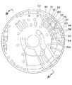
以下、本発明の実施の形態の一例を図1〜図6を参照して説明する。図1は本発明の実施の形態の一例であるトロイダル型無段自動変速機のエアブリーザ構造を説明するための要部断面図、図2はオイルポンプのカバー部をトランスミッションケースの内部側から見た平面図、図3は図2の背面図、図4は図3のIV−IV線断面図、図5はピストンをトランスミッションケースの内部側から見た平面図、図6は図5のVI−VI線断面図である。
【0010】
図1に示すように、トランスミッションケース1内には、回転駆動源に連結された入力軸2と、該入力軸2の右側に同心に連結される回転軸3とが配置され、入力軸2側には、トランスミッションケース1の軸方向の端部にボルト4を介して取り付けられたオイルポンプ5と、該オイルポンプ5の右側に隣接配置されて前進クラッチ(内側クラッチ)6及び後進ブレーキ(外側ブレーキ)7の操作により遊星歯車機構8を介して図示しないトロイダル変速機構に対する前後進の切換えを行う前後進切換機構9とが配設され、回転軸3側には、前記トロイダル変速機構が配設されている。
【0011】
両軸2,3間には、入力軸2にニードルベアリング12を介して回転自在に支持されて前後進切換機構9の遊星歯車機構8を構成するサンギヤ13と、このサンギヤ13に設けられた爪部13aに係合し且つ回転軸3に回転自在に支持されたローディングカム14と、このローディングカム14に係合ローラ15を介して連結され且つ回転軸3にボールスプライン16を介して支持された入力ディスク17とが介在されている。入力軸2からの回転力は前後進切換機構9を介してサンギヤ13の爪部13aからローディングカム14、係合ローラ15、入力ディスク17及びボールスプライン16を順次経由して回転軸3に伝達されるようになっている。
【0012】
ローディングカム14及び入力ディスク17の対向面には係合ローラ15が係合する波状のカム面がそれぞれ形成されており、ローディングカム14と入力ディスク17との間に供給された油圧により、係合ローラ15によるカム面のリードによるトルクに比例した推力に加えて、油圧に比例した回転軸3ひいてはトロイダル変速機構の入力軸2側への推力(移動力)を調整可能にしている。
【0013】
前後進切換機構9は、前進クラッチ6、後進ブレーキ7及び遊星歯車機構8によって構成されており、前進クラッチ7は、オイルポンプ5とサンギヤ13との間に位置して入力軸2に外嵌されたクラッチドラム18を備える。クラッチドラム18は入力軸2と一体的に回転するようになっており、該クラッチドラム18の径方向内側には遊星歯車機構8のサンギヤ13に支持されたクラッチハブ19が配設されている。クラッチドラム18とクラッチハブ19とは交互に配置されたクラッチディスク20を支持するようになっている。
【0014】
クラッチドラム18の基端部(オイルポンプ5側の端部)内はシリンダ室21とされており、該シリンダ室21にはピストン22が収容されている。ピストン22とシリンダ室21との間には油圧室23が形成されており、該油圧室23への作動油の供給を制御してピストン22を進退させることにより、クラッチディスク20を押圧するか又は該押圧を解除して前進クラッチ6の係合・離脱を行うようになっている。なお、図において符号24は、クラッチディスク20の押圧解除時に、ピストン22を元の位置に復帰させるリターンスプリングである。
【0015】
また、クラッチドラム18の先端側内周部にはリングギヤ25が取り付けられており、該リングギヤ25はピニオン26を介して上述したサンギヤ13に噛合している。ピニオン26は、キャリア27の互いに対向するキャリアプレート28a,28bに両端部が固定されたピニオンシャフト29に回転可能に支持されている。
【0016】
後進ブレーキ7は、クラッチドラム18の径方向外方に回転不能に配置されており、該後進ブレーキ7のブレーキドラム30は、オイルポンプ5の右側部からトロイダル変速機構側に向けて延びるドラム状の延設部材よって構成されてオイルポンプ5と一体化されている。ブレーキドラム30と前進クラッチ6のクラッチドラム18との間にはハブ31が配設されており、該ハブ31はキャリア27のトロイダル変速機構側のキャリアプレート28bに支持されている。ブレーキドラム30とハブ31とは交互に配置されたブレーキディスク32を支持するようになっている。
【0017】
なお、図1において符号33は、ブレーキドラム30の後進ブレーキ7よりトロイダル変速機構側の内周壁にスナップリング34を介して取り付けられた支持壁である。この支持壁33は、前後進切換機構9側で発生するキャリア27からのスラスト力を受け止めるべくキャリア27のトロイダル変速機構側のキャリアプレート28bに対向配置されており、これにより、前記スラスト力がトロイダル変速機構に伝わらないようにしている。
【0018】
オイルポンプ5は、円板状をなして中央部に入力軸2を回転可能に支持する支持孔5aが形成されており、軸方向に二つに分割された本体部35とカバー部36とを備える。本体部35及びカバー部36は共に鋳造により製作されており、本体部35とカバー部36とは分割面で接合されて固定ボルト37によって一体化されている。一体化されたオイルポンプ5は、カバー部36をトランスミッションケース1内に向けた状態で取付ボルト4を介してトランスミッションケース1の軸方向の端部に取り付けられている。
【0019】
ブレーキドラム30とクラッチドラム18との間に位置するカバー部36のトランスミッションケース1内を臨む部分には、図2及び図3に示すように、周方向全周に沿って延びる二条の周壁部37a,37bが径方向に互いに離間して形成されており、周壁部37a,37b間にはシリンダ室38が形成されている。シリンダ室38には円環状のピストン部材39が収納されており、ピストン部材39とシリンダ室38との間には油圧室41が形成されている。
【0020】
図5及び図6に示すように、ピストン部材39には、トランスミッションケース1内に向けて延びるピストン42が周方向に等間隔で4か所設けられている。油圧室41への作動油の供給を制御してピストン42を進退させることにより、ブレーキディスク32を押圧するか又は該押圧を解除して後進ブレーキ7の係合・離脱を行うようになっている。なお、図6及び図1において符号43は、ピストン部材39の各ピストン42間に設けられて該ピストン42によるブレーキディスク32の押圧解除時に、ピストン42を元の位置に復帰させるリターンスプリングである。
【0021】
そして、前進時には、前進クラッチ6のクラッチディスク20がピストン22により押圧されて該前進クラッチ6が係合状態とされ、後進ブレーキ7のブレーキディスク32はピストン42による押圧が解除されて該後進ブレーキ7が離脱状態とされている。かかる状態においては、入力軸2、クラッチドラム18、リングギヤ25、キャリア27及びサンギヤ13が一体となって同一方向に回転すし、これにより、該回転力がサンギヤ13の爪部13aに係合するローディングカム14を経てトロイダル変速機構に伝達される。
【0022】
一方、後進時には、前進クラッチ6のクラッチディスク20はピストン22による押圧が解除されて該前進クラッチ6が離脱状態とされ、後進ブレーキ7のブレーキディスク32がピストン42により押圧されて該後進ブレーキ7が係合状態とされ、ピニオン26の公転がハブ31及びキャリア27を介して阻止されている。かかる状態においては、入力軸2及びクラッチドラム18の一体的な回転力はリングギヤ25からピニオン26を介してサンギヤ13に伝達されるが、上述したようにピニオン26の公転が阻止されているため、サンギヤ13は入力軸2に対して反対方向に回転し、該回転力がサンギヤ13の爪部13aに係合するローディングカム14を経てトロイダル変速機構に伝達される。
【0023】
また、オイルポンプ5の本体部35とカバー部36との接合面間には、エアブリーザ室50が設けられている。エアブリーザ室50へのエア取入口51は、カバー部36のトランスミッションケース1内を臨む部分であって径方向の位置が後進ブレーキ7の径方向外方で且つピストン部材39より外側に位置して設けられている。これにより、エア取入口51とクラッチドラム18との間にピストン部材39のピストン42が配置されるようになっている。
【0024】
エアブリーザ室50は、オイルポンプ5の本体部35とカバー部36との各接合面に形成された凹部35a,36aを互いに対向させることにより、本体部35とカバー部36との接合面間に設けられたものであり、図3に示すように、上流側から下流側に向けて隔壁52を介して画成された第1の室53、第2の室54及び第3の室55を備える。カバー部36側の凹部36aを参照してエアブリーザ室50を説明すると、隔壁52の高さは凹部36aの深さに対応しており、また、第1〜第3の室53,54,55は互いに連通している。第1の室53はエア取入口51から流入したエアを図3において時計回り方向に導いて第2の室54に導入する通路として機能しており、第2の室54に導入されたエアの一部はエア取出口56から取り出される。第2の室54に残ったエアは第1の室53の径方向外方位置に隔壁52を介して設けられた第3の室55に流れ込み、該第3の室55のエア取出口57から取り出される。
【0025】
ここで、第1の室53と第2の室54との連通部58及び第2の室54と第3の室55との連通部59には凹部36a内を放射状に延びる補強リブ60が配置されている。補強リブ60は鋳造により得られたもので凹部36aの底部より若干高く且つ隔壁52より低く形成されており、これにより、第1の室53と第2の室54との連通部58に絞りが付与されるようになっている。また、第2の室54と第3の室55との連通部59は、隔壁52と該隔壁52の径方向外方位置に設けられた取付ボルト4用のボス部61との間に挟まれる位置に配置されており、このボス部61と上述した補強リブ60とによって連通部59に絞りが付与されるようになっている。
【0026】
上記の説明から明らかなように、かかる構成のトロイダル型無段自動変速機のエアブリーザ構造においては、エアブリーザ室50をオイルポンプ5内に設けるとともに、該エアブリーザ室50へのエア取入口51をカバー部36のトランスミッションケース1内を臨む部分であって径方向の位置が回転するクラッチドラム18より回転しない後進ブレーキ7の径方向外方に設けているため、後進ブレーキ7がクラッチドラム18などの遠心力で飛び散った油を遮る干渉材として機能してエア取入口51に油が直接入りにくくすることができる。
【0027】
また、エア取入口51とクラッチドラム18との間に後進ブレーキ7の係合・離脱を行うピストン42が配置されているため、クラッチドラム18の遠心力で飛び散った油の一部を後進ブレーキ7の手前で遮ることができるとともに、ピストン42と後進ブレーキ7とによってクラッチドラム18からエア取入口51までの空間に一種の迷路を形成することができ、この結果、遠心力により飛び散った油がエア取入口51へ直接入るのをより効果的に防止することができる。
【0028】
更に、上記エアブリーザ構造をトロイダル型無段自動変速機に用いることにより、エア取入口51を、出力ギヤなどが常時高速回転して内圧が非常に高くなるトロイダル変速機構側ではなく、内圧が比較的低いオイルポンプ5側に配置することができるため、上述した後進ブレーキ7及びピストン42の油遮断機能と相まってエア取入口51への油の侵入をより効果的に防止することができる。
【0029】
更に、鋳造により得られた補強リブ60と取付ボルト4用のボス部61とを用いて互いに隣り合う第2の室54と第3の室55との連通部59に絞りを付与することができるため、該連通部59の絞りを別途形成する必要がなくなり、製作の手間を軽減することができる。
【0030】
なお、上記実施の形態では、トロイダル型無段自動変速機に本発明を適用した場合を例に採ったが、これに限定されず、通常のオートマチックトランスミッション(AT)などにも本発明を適用できるのは勿論である。
【0031】
【発明の効果】
上記の説明から明らかなように、請求項1の発明によれば、エアブリーザ室をオイルポンプ内に設けるとともに、該エアブリーザ室へのエア取入口をオイルポンプのトランスミッションケース内を臨む部分であって径方向の位置が前記外側多板ブレーキの係合・離脱を行う円筒状ピストンより外側に位置して設けているため、円筒状ピストンがクラッチドラムなどの遠心力で飛び散った油を遮る干渉材として機能してエア取入口に油が直接入りにくくすることができ、トランスミッションケース内で上昇した圧を良好に取り出すことができるという効果が得られる。また、鋳造により得られた補強リブと取付ボルト用のボス部とを用いて、互いに隣り合う一組の室の連通部に絞りを付与することができるため、該連通部の絞りを別途形成する必要がなくなって制作の手間を軽減することができるという効果も得られる。
【0032】
請求項2の発明によれば、請求項1に加えて、エア取入口とクラッチドラムとの間に位置するオイルポンプのトランスミッションケース内を臨む部分に、周方向に沿って開口するシリンダ室を設け、該シリンダ室に前記円筒状ピストンを収容しているため、クラッチドラムの遠心力で飛び散った油の一部を外側多板ブレーキの手前で遮ることができるとともに、シリンダ室、ピストン及び外側多板ブレーキとによってクラッチドラムからエア取入口までの空間に一種の迷路を形成することができ、この結果、遠心力により飛び散った油がエア取入口へ直接入るのをより効果的に防止することができるという効果が得られる。
【0034】
請求項3の発明によれば、請求項1又は2に加えて、上記エアブリーザ構造をトロイダル型無段自動変速機に用いることにより、エア取入口を、出力ギヤなどが常時高速回転して内圧が非常に高くなるトロイダル変速機構側ではなく、内圧が比較的低いオイルポンプ側に配置することができるため、上述した外側ブレーキやピストンの油遮断機能と相まってエア取入口への油の浸入をより効果的に防止することができるという効果が得られる。
【図面の簡単な説明】
【図1】本発明の実施の形態の一例であるトロイダル型無段自動変速機のエアブリーザ構造を説明するための要部断面図である。
【図2】オイルポンプのカバーをトランスミッションケース内部側から見た平面図である。
【図3】図2の背面図である。
【図4】図3のIV−IV線断面図である。
【図5】ピストンをトランスミッションケースの内部側から見た平面図である。
【図6】図5のVI−VI線断面図である。
【符号の説明】
1…トランスミッションケース
5…オイルポンプ
6…前進クラッチ(内側クラッチ)
7…後進ブレーキ(外側多板クラッチ)
18…クラッチドラム
38…シリンダ室
42…ピストン(円筒状ピストン)
50…エアブリーザ室
51…エア取入口
52…隔壁
53…第1の室
54…第2の室
55…第3の室
58,59…連通部
60…補強リブ
61…取付ボルト用ボス部[0001]
TECHNICAL FIELD OF THE INVENTION
The present invention relates to an air breather structure for an automatic transmission.
[0002]
[Prior art]
2. Description of the Related Art A conventional air breather structure of an automatic transmission often has an air intake disposed near a rotating body such as a clutch drum.
[0003]
[Problems to be solved by the invention]
However, if the air intake is arranged near the rotating body, the oil scattered by the centrifugal force of the rotating body tends to directly enter the air intake, so that there is a disadvantage that only the increased pressure in the transmission case cannot be taken out.
[0004]
The present invention has been made in order to solve such inconvenience, and has been made to prevent oil scattered by centrifugal force from directly entering an air intake, and to be able to satisfactorily take out only the increased pressure in the transmission case. An object of the present invention is to provide an air breather structure for a transmission.
[0005]
[Means for Solving the Problems]
In order to achieve the above object, an air breather structure for an automatic transmission according to claim 1 is provided in an oil pump attached to an axial end of a transmission case and disposed in the transmission case adjacent to the oil pump. An inner clutch that has a clutch drum rotatably mounted and interrupts the rotational force by the operation of a built-in piston, and is mounted non-rotatably in the transmission case at a position radially outward of the clutch drum. In an air breather structure of an automatic transmission having an outer multi-plate brake, an air breather chamber is provided in the oil pump, and an air intake to the air breather chamber is a portion facing the transmission case of the oil pump. The radial position engages and disengages the outer multiple disc brake Provided with is located from the cylindrical piston outwardly, defining a plurality of chambers communicating with each other through the partition wall toward the downstream side of the air breather chamber made the oil pump casting from the upstream side, next to each other A communication portion of a set of mating chambers is arranged at a position sandwiched between the partition wall and a boss portion for mounting bolts to the transmission case, and a reinforcing rib obtained by casting is arranged at the bottom of the communication portion to form the communication portion. It is characterized in that an aperture is given to the part .
[0006]
An air breather structure for an automatic transmission according to a second aspect is the invention according to the first aspect, wherein a portion of the oil pump located between the air intake and the clutch drum facing the inside of the transmission case is provided with a circumferential direction. And a cylinder chamber that opens along the cylinder chamber, and the cylindrical piston is housed in the cylinder chamber.
[0007]
An air breather structure for an automatic transmission according to
[0009]
BEST MODE FOR CARRYING OUT THE INVENTION
Hereinafter, an example of an embodiment of the present invention will be described with reference to FIGS. FIG. 1 is a sectional view of an essential part for explaining an air breather structure of a toroidal type continuously variable automatic transmission which is an example of an embodiment of the present invention, and FIG. 2 is a view of a cover part of an oil pump viewed from the inside of a transmission case. FIG. 3 is a rear view of FIG. 2, FIG. 4 is a sectional view taken along line IV-IV of FIG. 3, FIG. 5 is a plan view of the piston as viewed from the inside of the transmission case, and FIG. 6 is VI-VI of FIG. It is a line sectional view.
[0010]
As shown in FIG. 1, an input shaft 2 connected to a rotary drive source and a
[0011]
A sun gear 13 rotatably supported by the input shaft 2 via a needle bearing 12 and constituting a
[0012]
Corrugated cam surfaces with which the
[0013]
The forward / reverse switching mechanism 9 includes a forward clutch 6, a
[0014]
The inside of the base end (the end on the
[0015]
A
[0016]
The
[0017]
In FIG. 1,
[0018]
The
[0019]
As shown in FIGS. 2 and 3, a portion of the
[0020]
As shown in FIGS. 5 and 6, the
[0021]
During forward movement, the
[0022]
On the other hand, at the time of reversing, the
[0023]
An
[0024]
The
[0025]
Here, reinforcing
[0026]
As is clear from the above description, in the air breather structure of the toroidal-type continuously variable automatic transmission having such a configuration, the
[0027]
Further, since the
[0028]
Further, by using the air breather structure in a toroidal-type continuously variable automatic transmission, the
[0029]
Further, the communicating
[0030]
In the above embodiment, the case where the present invention is applied to a toroidal-type continuously variable automatic transmission is taken as an example. However, the present invention is not limited to this, and the present invention can be applied to a normal automatic transmission (AT) and the like. Of course.
[0031]
【The invention's effect】
As is apparent from the above description, according to the invention of claim 1, the air breather chamber is provided in the oil pump, and the air intake to the air breather chamber is a portion facing the inside of the transmission case of the oil pump and having a diameter. Since the position in the direction is provided outside the cylindrical piston that engages and disengages the outer multiple disc brake, the cylindrical piston functions as an interference material that blocks oil scattered by centrifugal force such as a clutch drum. As a result, it is possible to make it difficult for oil to directly enter the air intake, and it is possible to obtain the effect that the pressure that has risen in the transmission case can be favorably taken out. In addition, a throttle can be given to a communicating portion of a pair of chambers adjacent to each other by using a reinforcing rib obtained by casting and a boss portion for a mounting bolt, so that a throttle for the communicating portion is separately formed. There is also an advantage that the need for production can be reduced by eliminating the need.
[0032]
According to the second aspect of the present invention, in addition to the first aspect, a cylinder chamber that opens in the circumferential direction is provided at a portion facing the inside of the transmission case of the oil pump located between the air intake and the clutch drum. Since the cylindrical piston is housed in the cylinder chamber, a part of the oil scattered by the centrifugal force of the clutch drum can be blocked before the outer multi-plate brake , and the cylinder chamber, the piston and the outer multi-plate can be blocked. A kind of maze can be formed in the space from the clutch drum to the air intake by the brake, and as a result, the oil scattered by centrifugal force can be more effectively prevented from directly entering the air intake. The effect is obtained.
[0034]
According to the third aspect of the present invention, in addition to the first or second aspect, by using the air breather structure in a toroidal-type continuously variable automatic transmission, the output gear or the like constantly rotates the air intake at a high speed to reduce the internal pressure. It can be located on the oil pump side where the internal pressure is relatively low, not on the toroidal transmission mechanism side where it becomes extremely high, so that oil penetration into the air intake is more effective in combination with the above-mentioned oil blocking function of the outer brake and piston The effect is obtained that it can be prevented.
[Brief description of the drawings]
FIG. 1 is a cross-sectional view of a main part for describing an air breather structure of a toroidal-type continuously variable automatic transmission that is an example of an embodiment of the present invention.
FIG. 2 is a plan view of the cover of the oil pump as viewed from the inside of a transmission case.
FIG. 3 is a rear view of FIG. 2;
FIG. 4 is a sectional view taken along line IV-IV of FIG. 3;
FIG. 5 is a plan view of the piston as viewed from the inside of the transmission case.
FIG. 6 is a sectional view taken along line VI-VI of FIG. 5;
[Explanation of symbols]
1: Transmission case 5: Oil pump 6: Forward clutch (inner clutch)
7. Reverse brake ( outside multiple disc clutch )
18
50
Claims (3)
前記オイルポンプ内にエアブリーザ室を設け、当該エアブリーザ室へのエア取入口を、前記オイルポンプの前記トランスミッションケース内を臨む部分であって径方向の位置が前記外側多板ブレーキの係合・離脱を行う円筒状ピストンより外側に位置して設けると共に、
前記オイルポンプを鋳造で製作して前記エアブリーザ室を上流側から下流側に向けて隔壁を介して互いに連通する複数の室に画成し、互いに隣り合う一組の室の連通部を前記隔壁と前記トランスミッションケースへの取付ボルト用ボス部とで挟まれる位置に配置し、前記連通部の底部に鋳造により得られた補強リブを配置して該連通部に絞りを与えたことを特徴とする自動変速機のエアブリーザ構造。An oil pump attached to an axial end of the transmission case, and a clutch drum disposed in the transmission case adjacent to the oil pump and rotatably mounted, and having a built-in piston to actuate a rotational force. An air breather structure for an automatic transmission, comprising: an inner clutch to be engaged; and an outer multi-plate brake which is positioned radially outward of the clutch drum and is non-rotatably mounted in the transmission case.
An air breather chamber is provided in the oil pump, and an air intake to the air breather chamber is a portion facing the inside of the transmission case of the oil pump, and a radial position of the air breather chamber engages and disengages the outer multiple disc brake. Along with being provided outside the cylindrical piston to be performed ,
The oil pump is manufactured by casting to define the air breather chamber into a plurality of chambers communicating with each other through a partition from the upstream side to the downstream side, and a communication portion of a pair of chambers adjacent to each other with the partition wall. The automatic transmission is characterized in that it is arranged at a position sandwiched by a boss for a mounting bolt to the transmission case, and a reinforcing rib obtained by casting is arranged at the bottom of the communication part to give a throttle to the communication part. Transmission air breather structure.
Priority Applications (1)
| Application Number | Priority Date | Filing Date | Title |
|---|---|---|---|
| JP11988697A JP3568736B2 (en) | 1997-05-09 | 1997-05-09 | Air breather structure for automatic transmission |
Applications Claiming Priority (1)
| Application Number | Priority Date | Filing Date | Title |
|---|---|---|---|
| JP11988697A JP3568736B2 (en) | 1997-05-09 | 1997-05-09 | Air breather structure for automatic transmission |
Publications (2)
| Publication Number | Publication Date |
|---|---|
| JPH10311408A JPH10311408A (en) | 1998-11-24 |
| JP3568736B2 true JP3568736B2 (en) | 2004-09-22 |
Family
ID=14772678
Family Applications (1)
| Application Number | Title | Priority Date | Filing Date |
|---|---|---|---|
| JP11988697A Expired - Fee Related JP3568736B2 (en) | 1997-05-09 | 1997-05-09 | Air breather structure for automatic transmission |
Country Status (1)
| Country | Link |
|---|---|
| JP (1) | JP3568736B2 (en) |
Families Citing this family (8)
| Publication number | Priority date | Publication date | Assignee | Title |
|---|---|---|---|---|
| DE50305259D1 (en) * | 2003-05-15 | 2006-11-16 | Ford Global Tech Llc | casing |
| JP4350692B2 (en) * | 2005-09-21 | 2009-10-21 | ジヤトコ株式会社 | Automatic transmission |
| KR100793703B1 (en) | 2006-09-29 | 2008-01-11 | 현대 파워텍 주식회사 | An air breather for transmission |
| KR100903321B1 (en) | 2007-10-23 | 2009-06-18 | 현대자동차주식회사 | Thrust removing apparatus of automatic transmission |
| JP5392195B2 (en) * | 2010-06-15 | 2014-01-22 | アイシン・エィ・ダブリュ株式会社 | Automatic transmission brake mechanism |
| JP2014173685A (en) * | 2013-03-11 | 2014-09-22 | Jatco Ltd | Seal structure, seal structure of differential mechanism and manufacturing method of seal structure |
| DE102017121056A1 (en) * | 2017-09-12 | 2019-03-14 | Dr. Ing. H.C. F. Porsche Ag | Transmission with an oil guide device |
| DE102022210237A1 (en) * | 2022-09-28 | 2024-03-28 | Zf Friedrichshafen Ag | Gearbox housing |
-
1997
- 1997-05-09 JP JP11988697A patent/JP3568736B2/en not_active Expired - Fee Related
Also Published As
| Publication number | Publication date |
|---|---|
| JPH10311408A (en) | 1998-11-24 |
Similar Documents
| Publication | Publication Date | Title |
|---|---|---|
| US8286773B2 (en) | Frictional engagement apparatus | |
| JP2008502859A (en) | Planar coupling device assembly for automatic transmission | |
| JP2677397B2 (en) | Hydraulically actuated starting clutch | |
| US5020646A (en) | Torque converter device | |
| US6878086B2 (en) | Automatic transmission | |
| JP3568736B2 (en) | Air breather structure for automatic transmission | |
| JPH0251648A (en) | Structure for oil passage of automatic transmission | |
| JP3369437B2 (en) | Support wall structure for toroidal type continuously variable automatic transmission | |
| JPH0617691B2 (en) | Friction type automatic starter | |
| JPH0424577B2 (en) | ||
| JP3696664B2 (en) | Multi-plate clutch structure | |
| JP3777055B2 (en) | Connecting structure of planetary gear mechanism and friction fastening mechanism in automatic transmission | |
| JPH04107324A (en) | Wet type multiple disk clutch | |
| JPH0419425A (en) | Wet clutch | |
| JP2558970Y2 (en) | Disc brake device for automatic transmission | |
| JPS6325213B2 (en) | ||
| JP4585087B2 (en) | Automatic transmission | |
| JP3524394B2 (en) | transmission | |
| JP4012273B2 (en) | Multi-plate friction engagement device | |
| JPH0649959Y2 (en) | Automatic transmission | |
| JPH10213191A (en) | Automatic transmission and assembling method thereof | |
| JPH01210624A (en) | Clutch drum structure of automatic transmission | |
| JP7129301B2 (en) | friction engagement device | |
| JPH0453461Y2 (en) | ||
| JPH0453460Y2 (en) |
Legal Events
| Date | Code | Title | Description |
|---|---|---|---|
| A131 | Notification of reasons for refusal |
Free format text: JAPANESE INTERMEDIATE CODE: A131 Effective date: 20040217 |
|
| A521 | Written amendment |
Free format text: JAPANESE INTERMEDIATE CODE: A523 Effective date: 20040416 |
|
| TRDD | Decision of grant or rejection written | ||
| A01 | Written decision to grant a patent or to grant a registration (utility model) |
Free format text: JAPANESE INTERMEDIATE CODE: A01 Effective date: 20040525 |
|
| A61 | First payment of annual fees (during grant procedure) |
Free format text: JAPANESE INTERMEDIATE CODE: A61 Effective date: 20040616 |
|
| R150 | Certificate of patent (=grant) or registration of utility model |
Free format text: JAPANESE INTERMEDIATE CODE: R150 |
|
| FPAY | Renewal fee payment (prs date is renewal date of database) |
Free format text: PAYMENT UNTIL: 20080625 Year of fee payment: 4 |
|
| FPAY | Renewal fee payment (prs date is renewal date of database) |
Free format text: PAYMENT UNTIL: 20090625 Year of fee payment: 5 |
|
| FPAY | Renewal fee payment (prs date is renewal date of database) |
Free format text: PAYMENT UNTIL: 20090625 Year of fee payment: 5 |
|
| FPAY | Renewal fee payment (prs date is renewal date of database) |
Free format text: PAYMENT UNTIL: 20100625 Year of fee payment: 6 |
|
| FPAY | Renewal fee payment (prs date is renewal date of database) |
Free format text: PAYMENT UNTIL: 20100625 Year of fee payment: 6 |
|
| FPAY | Renewal fee payment (prs date is renewal date of database) |
Free format text: PAYMENT UNTIL: 20110625 Year of fee payment: 7 |
|
| FPAY | Renewal fee payment (prs date is renewal date of database) |
Free format text: PAYMENT UNTIL: 20110625 Year of fee payment: 7 |
|
| FPAY | Renewal fee payment (prs date is renewal date of database) |
Free format text: PAYMENT UNTIL: 20120625 Year of fee payment: 8 |
|
| FPAY | Renewal fee payment (prs date is renewal date of database) |
Free format text: PAYMENT UNTIL: 20120625 Year of fee payment: 8 |
|
| FPAY | Renewal fee payment (prs date is renewal date of database) |
Free format text: PAYMENT UNTIL: 20130625 Year of fee payment: 9 |
|
| FPAY | Renewal fee payment (prs date is renewal date of database) |
Free format text: PAYMENT UNTIL: 20130625 Year of fee payment: 9 |
|
| FPAY | Renewal fee payment (prs date is renewal date of database) |
Free format text: PAYMENT UNTIL: 20140625 Year of fee payment: 10 |
|
| S111 | Request for change of ownership or part of ownership |
Free format text: JAPANESE INTERMEDIATE CODE: R313117 |
|
| R350 | Written notification of registration of transfer |
Free format text: JAPANESE INTERMEDIATE CODE: R350 |
|
| LAPS | Cancellation because of no payment of annual fees |