JP3566147B2 - Hybrid vehicle cooling fan failure detection device - Google Patents
Hybrid vehicle cooling fan failure detection device Download PDFInfo
- Publication number
- JP3566147B2 JP3566147B2 JP26123999A JP26123999A JP3566147B2 JP 3566147 B2 JP3566147 B2 JP 3566147B2 JP 26123999 A JP26123999 A JP 26123999A JP 26123999 A JP26123999 A JP 26123999A JP 3566147 B2 JP3566147 B2 JP 3566147B2
- Authority
- JP
- Japan
- Prior art keywords
- battery
- cooling fan
- temperature change
- change amount
- motor
- Prior art date
- Legal status (The legal status is an assumption and is not a legal conclusion. Google has not performed a legal analysis and makes no representation as to the accuracy of the status listed.)
- Expired - Fee Related
Links
- 238000001816 cooling Methods 0.000 title claims description 111
- 238000001514 detection method Methods 0.000 title claims description 52
- 230000020169 heat generation Effects 0.000 claims description 7
- 239000003507 refrigerant Substances 0.000 description 11
- 238000000034 method Methods 0.000 description 7
- 230000000694 effects Effects 0.000 description 6
- 230000008929 regeneration Effects 0.000 description 5
- 238000011069 regeneration method Methods 0.000 description 5
- 238000010586 diagram Methods 0.000 description 4
- 238000007599 discharging Methods 0.000 description 4
- 239000000446 fuel Substances 0.000 description 4
- 230000006870 function Effects 0.000 description 4
- 230000010354 integration Effects 0.000 description 4
- 230000005540 biological transmission Effects 0.000 description 3
- 230000007423 decrease Effects 0.000 description 3
- 230000004044 response Effects 0.000 description 2
- 230000002159 abnormal effect Effects 0.000 description 1
- 230000005856 abnormality Effects 0.000 description 1
- 230000001133 acceleration Effects 0.000 description 1
- 238000002485 combustion reaction Methods 0.000 description 1
- 230000006866 deterioration Effects 0.000 description 1
- 230000007659 motor function Effects 0.000 description 1
- 230000001141 propulsive effect Effects 0.000 description 1
- 230000001172 regenerating effect Effects 0.000 description 1
Images


Classifications
-
- B—PERFORMING OPERATIONS; TRANSPORTING
- B60—VEHICLES IN GENERAL
- B60W—CONJOINT CONTROL OF VEHICLE SUB-UNITS OF DIFFERENT TYPE OR DIFFERENT FUNCTION; CONTROL SYSTEMS SPECIALLY ADAPTED FOR HYBRID VEHICLES; ROAD VEHICLE DRIVE CONTROL SYSTEMS FOR PURPOSES NOT RELATED TO THE CONTROL OF A PARTICULAR SUB-UNIT
- B60W10/00—Conjoint control of vehicle sub-units of different type or different function
- B60W10/24—Conjoint control of vehicle sub-units of different type or different function including control of energy storage means
- B60W10/26—Conjoint control of vehicle sub-units of different type or different function including control of energy storage means for electrical energy, e.g. batteries or capacitors
-
- B—PERFORMING OPERATIONS; TRANSPORTING
- B60—VEHICLES IN GENERAL
- B60K—ARRANGEMENT OR MOUNTING OF PROPULSION UNITS OR OF TRANSMISSIONS IN VEHICLES; ARRANGEMENT OR MOUNTING OF PLURAL DIVERSE PRIME-MOVERS IN VEHICLES; AUXILIARY DRIVES FOR VEHICLES; INSTRUMENTATION OR DASHBOARDS FOR VEHICLES; ARRANGEMENTS IN CONNECTION WITH COOLING, AIR INTAKE, GAS EXHAUST OR FUEL SUPPLY OF PROPULSION UNITS IN VEHICLES
- B60K6/00—Arrangement or mounting of plural diverse prime-movers for mutual or common propulsion, e.g. hybrid propulsion systems comprising electric motors and internal combustion engines ; Control systems therefor, i.e. systems controlling two or more prime movers, or controlling one of these prime movers and any of the transmission, drive or drive units Informative references: mechanical gearings with secondary electric drive F16H3/72; arrangements for handling mechanical energy structurally associated with the dynamo-electric machine H02K7/00; machines comprising structurally interrelated motor and generator parts H02K51/00; dynamo-electric machines not otherwise provided for in H02K see H02K99/00
- B60K6/20—Arrangement or mounting of plural diverse prime-movers for mutual or common propulsion, e.g. hybrid propulsion systems comprising electric motors and internal combustion engines ; Control systems therefor, i.e. systems controlling two or more prime movers, or controlling one of these prime movers and any of the transmission, drive or drive units Informative references: mechanical gearings with secondary electric drive F16H3/72; arrangements for handling mechanical energy structurally associated with the dynamo-electric machine H02K7/00; machines comprising structurally interrelated motor and generator parts H02K51/00; dynamo-electric machines not otherwise provided for in H02K see H02K99/00 the prime-movers consisting of electric motors and internal combustion engines, e.g. HEVs
- B60K6/42—Arrangement or mounting of plural diverse prime-movers for mutual or common propulsion, e.g. hybrid propulsion systems comprising electric motors and internal combustion engines ; Control systems therefor, i.e. systems controlling two or more prime movers, or controlling one of these prime movers and any of the transmission, drive or drive units Informative references: mechanical gearings with secondary electric drive F16H3/72; arrangements for handling mechanical energy structurally associated with the dynamo-electric machine H02K7/00; machines comprising structurally interrelated motor and generator parts H02K51/00; dynamo-electric machines not otherwise provided for in H02K see H02K99/00 the prime-movers consisting of electric motors and internal combustion engines, e.g. HEVs characterised by the architecture of the hybrid electric vehicle
- B60K6/48—Parallel type
- B60K6/485—Motor-assist type
-
- B—PERFORMING OPERATIONS; TRANSPORTING
- B60—VEHICLES IN GENERAL
- B60L—PROPULSION OF ELECTRICALLY-PROPELLED VEHICLES; SUPPLYING ELECTRIC POWER FOR AUXILIARY EQUIPMENT OF ELECTRICALLY-PROPELLED VEHICLES; ELECTRODYNAMIC BRAKE SYSTEMS FOR VEHICLES IN GENERAL; MAGNETIC SUSPENSION OR LEVITATION FOR VEHICLES; MONITORING OPERATING VARIABLES OF ELECTRICALLY-PROPELLED VEHICLES; ELECTRIC SAFETY DEVICES FOR ELECTRICALLY-PROPELLED VEHICLES
- B60L50/00—Electric propulsion with power supplied within the vehicle
- B60L50/10—Electric propulsion with power supplied within the vehicle using propulsion power supplied by engine-driven generators, e.g. generators driven by combustion engines
- B60L50/15—Electric propulsion with power supplied within the vehicle using propulsion power supplied by engine-driven generators, e.g. generators driven by combustion engines with additional electric power supply
-
- B—PERFORMING OPERATIONS; TRANSPORTING
- B60—VEHICLES IN GENERAL
- B60L—PROPULSION OF ELECTRICALLY-PROPELLED VEHICLES; SUPPLYING ELECTRIC POWER FOR AUXILIARY EQUIPMENT OF ELECTRICALLY-PROPELLED VEHICLES; ELECTRODYNAMIC BRAKE SYSTEMS FOR VEHICLES IN GENERAL; MAGNETIC SUSPENSION OR LEVITATION FOR VEHICLES; MONITORING OPERATING VARIABLES OF ELECTRICALLY-PROPELLED VEHICLES; ELECTRIC SAFETY DEVICES FOR ELECTRICALLY-PROPELLED VEHICLES
- B60L58/00—Methods or circuit arrangements for monitoring or controlling batteries or fuel cells, specially adapted for electric vehicles
- B60L58/10—Methods or circuit arrangements for monitoring or controlling batteries or fuel cells, specially adapted for electric vehicles for monitoring or controlling batteries
- B60L58/24—Methods or circuit arrangements for monitoring or controlling batteries or fuel cells, specially adapted for electric vehicles for monitoring or controlling batteries for controlling the temperature of batteries
- B60L58/26—Methods or circuit arrangements for monitoring or controlling batteries or fuel cells, specially adapted for electric vehicles for monitoring or controlling batteries for controlling the temperature of batteries by cooling
-
- H—ELECTRICITY
- H01—ELECTRIC ELEMENTS
- H01M—PROCESSES OR MEANS, e.g. BATTERIES, FOR THE DIRECT CONVERSION OF CHEMICAL ENERGY INTO ELECTRICAL ENERGY
- H01M10/00—Secondary cells; Manufacture thereof
- H01M10/60—Heating or cooling; Temperature control
- H01M10/61—Types of temperature control
- H01M10/613—Cooling or keeping cold
-
- H—ELECTRICITY
- H01—ELECTRIC ELEMENTS
- H01M—PROCESSES OR MEANS, e.g. BATTERIES, FOR THE DIRECT CONVERSION OF CHEMICAL ENERGY INTO ELECTRICAL ENERGY
- H01M10/00—Secondary cells; Manufacture thereof
- H01M10/60—Heating or cooling; Temperature control
- H01M10/62—Heating or cooling; Temperature control specially adapted for specific applications
- H01M10/625—Vehicles
-
- H—ELECTRICITY
- H01—ELECTRIC ELEMENTS
- H01M—PROCESSES OR MEANS, e.g. BATTERIES, FOR THE DIRECT CONVERSION OF CHEMICAL ENERGY INTO ELECTRICAL ENERGY
- H01M10/00—Secondary cells; Manufacture thereof
- H01M10/60—Heating or cooling; Temperature control
- H01M10/63—Control systems
- H01M10/633—Control systems characterised by algorithms, flow charts, software details or the like
-
- H—ELECTRICITY
- H01—ELECTRIC ELEMENTS
- H01M—PROCESSES OR MEANS, e.g. BATTERIES, FOR THE DIRECT CONVERSION OF CHEMICAL ENERGY INTO ELECTRICAL ENERGY
- H01M10/00—Secondary cells; Manufacture thereof
- H01M10/60—Heating or cooling; Temperature control
- H01M10/65—Means for temperature control structurally associated with the cells
- H01M10/656—Means for temperature control structurally associated with the cells characterised by the type of heat-exchange fluid
- H01M10/6561—Gases
- H01M10/6563—Gases with forced flow, e.g. by blowers
-
- B—PERFORMING OPERATIONS; TRANSPORTING
- B60—VEHICLES IN GENERAL
- B60K—ARRANGEMENT OR MOUNTING OF PROPULSION UNITS OR OF TRANSMISSIONS IN VEHICLES; ARRANGEMENT OR MOUNTING OF PLURAL DIVERSE PRIME-MOVERS IN VEHICLES; AUXILIARY DRIVES FOR VEHICLES; INSTRUMENTATION OR DASHBOARDS FOR VEHICLES; ARRANGEMENTS IN CONNECTION WITH COOLING, AIR INTAKE, GAS EXHAUST OR FUEL SUPPLY OF PROPULSION UNITS IN VEHICLES
- B60K11/00—Arrangement in connection with cooling of propulsion units
- B60K11/06—Arrangement in connection with cooling of propulsion units with air cooling
-
- B—PERFORMING OPERATIONS; TRANSPORTING
- B60—VEHICLES IN GENERAL
- B60K—ARRANGEMENT OR MOUNTING OF PROPULSION UNITS OR OF TRANSMISSIONS IN VEHICLES; ARRANGEMENT OR MOUNTING OF PLURAL DIVERSE PRIME-MOVERS IN VEHICLES; AUXILIARY DRIVES FOR VEHICLES; INSTRUMENTATION OR DASHBOARDS FOR VEHICLES; ARRANGEMENTS IN CONNECTION WITH COOLING, AIR INTAKE, GAS EXHAUST OR FUEL SUPPLY OF PROPULSION UNITS IN VEHICLES
- B60K1/00—Arrangement or mounting of electrical propulsion units
- B60K2001/003—Arrangement or mounting of electrical propulsion units with means for cooling the electrical propulsion units
-
- B—PERFORMING OPERATIONS; TRANSPORTING
- B60—VEHICLES IN GENERAL
- B60L—PROPULSION OF ELECTRICALLY-PROPELLED VEHICLES; SUPPLYING ELECTRIC POWER FOR AUXILIARY EQUIPMENT OF ELECTRICALLY-PROPELLED VEHICLES; ELECTRODYNAMIC BRAKE SYSTEMS FOR VEHICLES IN GENERAL; MAGNETIC SUSPENSION OR LEVITATION FOR VEHICLES; MONITORING OPERATING VARIABLES OF ELECTRICALLY-PROPELLED VEHICLES; ELECTRIC SAFETY DEVICES FOR ELECTRICALLY-PROPELLED VEHICLES
- B60L2240/00—Control parameters of input or output; Target parameters
- B60L2240/40—Drive Train control parameters
- B60L2240/54—Drive Train control parameters related to batteries
- B60L2240/545—Temperature
-
- B—PERFORMING OPERATIONS; TRANSPORTING
- B60—VEHICLES IN GENERAL
- B60W—CONJOINT CONTROL OF VEHICLE SUB-UNITS OF DIFFERENT TYPE OR DIFFERENT FUNCTION; CONTROL SYSTEMS SPECIALLY ADAPTED FOR HYBRID VEHICLES; ROAD VEHICLE DRIVE CONTROL SYSTEMS FOR PURPOSES NOT RELATED TO THE CONTROL OF A PARTICULAR SUB-UNIT
- B60W50/00—Details of control systems for road vehicle drive control not related to the control of a particular sub-unit, e.g. process diagnostic or vehicle driver interfaces
- B60W50/02—Ensuring safety in case of control system failures, e.g. by diagnosing, circumventing or fixing failures
- B60W50/0205—Diagnosing or detecting failures; Failure detection models
- B60W2050/021—Means for detecting failure or malfunction
-
- Y—GENERAL TAGGING OF NEW TECHNOLOGICAL DEVELOPMENTS; GENERAL TAGGING OF CROSS-SECTIONAL TECHNOLOGIES SPANNING OVER SEVERAL SECTIONS OF THE IPC; TECHNICAL SUBJECTS COVERED BY FORMER USPC CROSS-REFERENCE ART COLLECTIONS [XRACs] AND DIGESTS
- Y02—TECHNOLOGIES OR APPLICATIONS FOR MITIGATION OR ADAPTATION AGAINST CLIMATE CHANGE
- Y02E—REDUCTION OF GREENHOUSE GAS [GHG] EMISSIONS, RELATED TO ENERGY GENERATION, TRANSMISSION OR DISTRIBUTION
- Y02E60/00—Enabling technologies; Technologies with a potential or indirect contribution to GHG emissions mitigation
- Y02E60/10—Energy storage using batteries
-
- Y—GENERAL TAGGING OF NEW TECHNOLOGICAL DEVELOPMENTS; GENERAL TAGGING OF CROSS-SECTIONAL TECHNOLOGIES SPANNING OVER SEVERAL SECTIONS OF THE IPC; TECHNICAL SUBJECTS COVERED BY FORMER USPC CROSS-REFERENCE ART COLLECTIONS [XRACs] AND DIGESTS
- Y02—TECHNOLOGIES OR APPLICATIONS FOR MITIGATION OR ADAPTATION AGAINST CLIMATE CHANGE
- Y02T—CLIMATE CHANGE MITIGATION TECHNOLOGIES RELATED TO TRANSPORTATION
- Y02T10/00—Road transport of goods or passengers
- Y02T10/60—Other road transportation technologies with climate change mitigation effect
- Y02T10/62—Hybrid vehicles
-
- Y—GENERAL TAGGING OF NEW TECHNOLOGICAL DEVELOPMENTS; GENERAL TAGGING OF CROSS-SECTIONAL TECHNOLOGIES SPANNING OVER SEVERAL SECTIONS OF THE IPC; TECHNICAL SUBJECTS COVERED BY FORMER USPC CROSS-REFERENCE ART COLLECTIONS [XRACs] AND DIGESTS
- Y02—TECHNOLOGIES OR APPLICATIONS FOR MITIGATION OR ADAPTATION AGAINST CLIMATE CHANGE
- Y02T—CLIMATE CHANGE MITIGATION TECHNOLOGIES RELATED TO TRANSPORTATION
- Y02T10/00—Road transport of goods or passengers
- Y02T10/60—Other road transportation technologies with climate change mitigation effect
- Y02T10/70—Energy storage systems for electromobility, e.g. batteries
-
- Y—GENERAL TAGGING OF NEW TECHNOLOGICAL DEVELOPMENTS; GENERAL TAGGING OF CROSS-SECTIONAL TECHNOLOGIES SPANNING OVER SEVERAL SECTIONS OF THE IPC; TECHNICAL SUBJECTS COVERED BY FORMER USPC CROSS-REFERENCE ART COLLECTIONS [XRACs] AND DIGESTS
- Y02—TECHNOLOGIES OR APPLICATIONS FOR MITIGATION OR ADAPTATION AGAINST CLIMATE CHANGE
- Y02T—CLIMATE CHANGE MITIGATION TECHNOLOGIES RELATED TO TRANSPORTATION
- Y02T10/00—Road transport of goods or passengers
- Y02T10/60—Other road transportation technologies with climate change mitigation effect
- Y02T10/7072—Electromobility specific charging systems or methods for batteries, ultracapacitors, supercapacitors or double-layer capacitors
-
- Y—GENERAL TAGGING OF NEW TECHNOLOGICAL DEVELOPMENTS; GENERAL TAGGING OF CROSS-SECTIONAL TECHNOLOGIES SPANNING OVER SEVERAL SECTIONS OF THE IPC; TECHNICAL SUBJECTS COVERED BY FORMER USPC CROSS-REFERENCE ART COLLECTIONS [XRACs] AND DIGESTS
- Y10—TECHNICAL SUBJECTS COVERED BY FORMER USPC
- Y10S—TECHNICAL SUBJECTS COVERED BY FORMER USPC CROSS-REFERENCE ART COLLECTIONS [XRACs] AND DIGESTS
- Y10S903/00—Hybrid electric vehicles, HEVS
- Y10S903/902—Prime movers comprising electrical and internal combustion motors
- Y10S903/903—Prime movers comprising electrical and internal combustion motors having energy storing means, e.g. battery, capacitor
Landscapes
- Engineering & Computer Science (AREA)
- Chemical & Material Sciences (AREA)
- Electrochemistry (AREA)
- General Chemical & Material Sciences (AREA)
- Mechanical Engineering (AREA)
- Transportation (AREA)
- Manufacturing & Machinery (AREA)
- Chemical Kinetics & Catalysis (AREA)
- Power Engineering (AREA)
- Combustion & Propulsion (AREA)
- Automation & Control Theory (AREA)
- Life Sciences & Earth Sciences (AREA)
- Sustainable Development (AREA)
- Sustainable Energy (AREA)
- Electric Propulsion And Braking For Vehicles (AREA)
- Hybrid Electric Vehicles (AREA)
- Secondary Cells (AREA)
Description
【0001】
【発明の属する技術分野】
この発明は、ハイブリッド車両に搭載されるバッテリの冷却を行う冷却ファンの故障検知装置に関するものである。
【0002】
【従来の技術】
従来から、走行用の動力源としてエンジンの他にモータを備えたハイブリッド車両が知られている。ハイブリッド車両にはシリーズハイブリッド車とパラレルハイブリッド車がある。シリーズハイブリッド車はエンジンによって駆動される発電機の発電出力等を用いてモータを駆動し、モータによって車輪を駆動する車両である。
したがって、エンジンと車輪が機械的に連結されていないため、エンジンを高燃費低エミッションの回転数領域にてほぼ一定回転で運転することができ、従来のエンジン車両に比べ良好な燃費及び低いエミッションを実現できる。
【0003】
これに対しパラレルハイブリッド車は、エンジンに連結されたモータによってエンジンの駆動軸を駆動補助すると共に、このモータを発電機として使用して得られた電気エネルギーを蓄電装置に充電し、さらにこの発電された電気エネルギーは車両内の電装品にも用いられる。
したがって、エンジンの運転負荷を軽減できるため、やはり従来のエンジン車に比べ良好な燃費及び低エミッションを実現できる。
【0004】
上記パラレルハイブリッド車には、エンジンの出力軸にエンジンの出力を補助するモータが直結され、このモータが減速時等に発電機として機能してバッテリ等に蓄電をするタイプや、エンジンとモータのいずれか、あるいは、双方で駆動力を発生することができ発電機を別に備えたタイプのもの等がある。
このようなハイブリッド車両にあっては、例えば、加速時においてはモータによってエンジンの出力を補助し、減速時においては減速回生によってバッテリ等への充電を行なう等様々な制御を行い、バッテリの電気エネルギー(以下、バッテリ残容量という)を確保して運転者の要求に対応できるようになっている。
【0005】
【発明が解決しようとする課題】
ところで、ハイブリッド車両に用いられるバッテリは、バッテリ自身の温度が上昇すると充電効率が急激に低下してしまう温度が存在する。この温度はバッテリの性能によって予め決まっている温度である。バッテリの温度がこの温度を超えている状態において充電を行っても熱に変換されるだけで、充電された電力をバッテリに蓄えることができない。また、バッテリの温度が高い状態で充放電を行うとさらなる温度上昇が発生し、バッテリを劣化させてしまう。このため、車両に搭載されるバッテリはバッテリ自身を冷却する冷却ファンが備えられ、充電効率が急激に低下してしまう温度以下にバッテリ温度が保たれるようになっている。
【0006】
しかしながら、冷却ファンが何らかの原因によって故障していることを知らずにバッテリの充放電を行うとバッテリの温度上昇が顕著になりバッテリの劣化を早めてしまう。そこで、冷却ファンが故障したこと検知する装置が必要となる。ところが、冷却ファンの故障検知を行うには、故障検知をするセンサや故障検知回路等を新たに備える必要があり、コストアップや車両重量の増加を招くという問題がある。また、断線ショート検出などの電気的な検出方法では冷媒の吸気口や排気口が何らかの原因で塞がれることによって冷却能力が低下していることを検出することは困難であるという問題もある。
【0007】
本発明は、このような事情に鑑みてなされたもので、新たに故障検知回路やセンサを設けることなく冷却ファンの故障検知を行うことができるハイブリッド車両の冷却ファン故障検知装置を提供するものである。
【0008】
【課題を解決するための手段】
請求項1に記載の発明は、車両の推進力を出力するエンジン(例えば、実施形態におけるエンジン1)と、エンジンの出力を補助する補助駆動力を発生するモータ(例えば、実施形態におけるモータ2)と、該モータに電力を供給すると共に補助駆動力が必要ないときにモータを発電機として作動させて得られた電気エネルギーを充電するバッテリ(例えば、実施形態におけるバッテリ3)と該バッテリを冷却する冷却ファン(例えば、実施形態における冷却ファン18)とを備えたハイブリッド車両の冷却ファン故障検知装置であって、前記冷却ファン故障検知装置は、前記冷却ファンの冷却能力を算出する冷却能力算出手段(例えば、実施形態における温度差算出部62)と、前記バッテリの発熱量を算出するバッテリ発熱量算出手段(例えば、実施形態における入出力電力算出部61)と、前記発熱量と前記冷却能力とから前記バッテリの想定温度変化量を算出する想定温度変化量算出手段(例えば、実施形態における想定温度変化量算出部63)と、前記バッテリの実温度変化量を算出する実温度変化量算出手段(例えば、実施形態における実温度変化量算出部64)と、前記想定温度変化量算出部において算出された想定温度変化量と実温度変化量算出部において算出された実温度変化量とを比較した結果に基づいて前記冷却ファンの故障を検知する故障判定手段(例えば、実施形態における故障判定部66)とを備え、前記故障判定手段が前記冷却ファンを故障と判断した場合には、前記モータの使用を制限して、前記エンジンのみで走行する制御を行うことを特徴とする。
【0009】
請求項1に記載の発明によれば、バッテリの発熱量と冷却ファンの冷却能力とからバッテリの想定温度変化量を算出する想定温度変化量算出手段と、バッテリの実温度変化量を算出する実温度変化量算出手段と、想定温度変化量算出部において算出された想定温度変化量と実温度変化量算出部において算出された実温度変化量とを比較した結果に基づいて冷却ファンの故障を検知する故障判定手段とを備え、既に備えられているセンサ出力に基づき演算処理によって冷却ファンの故障を検知するようにしたため、新たに故障検知に必要なセンサ類を設けることなく冷却ファンの故障を検知することができるという効果が得られる。また、バッテリ温度の変化量に基づいて故障の判定を行うようにしたため、吸気口や排気口が塞がれることにより冷却能力が低下したことも検知することができるという効果も得られる。
また、請求項2に記載の発明は、前記故障判定手段は、前記バッテリの温度上昇に基づいて前記モータの使用を制限するパワーセーブが実施されている場合に、前記冷却ファンの故障検知を開始することを特徴とする。
【0010】
【発明の実施の形態】
以下、本発明の一実施形態によるハイブリッド車両の制御装置を図面を参照して説明する。
図1は、この発明の一実施形態によるハイブリッド車両の一種であるパラレルハイブリッド車の全体構成を示すブロック図である。この図において、符号1は燃料の燃焼エネルギーで作動するエンジンであり、符号2はエンジンと併用して用いられ電気エネルギーで作動するモータである。エンジン1及びモータ2の両方の駆動力は、オートマチックトランスミッションあるいはマニュアルトランスミッションよりなるトランスミッション(図示せず)を介して駆動輪(図示せず)に伝達される。また、ハイブリッド車両の減速時には、駆動輪からモータ2に駆動力が伝達され、モータ2は発電機として機能し、車体の運動エネルギーを電気エネルギーとして回収する。
【0011】
符号3は、モータ2に電力を供給すると共に駆動力が必要ないときにモータを発電機として作動させて得られた電気エネルギーを充電するバッテリである。ここで、バッテリ3は、例えば、複数のセルを直列に接続したモジュールを1単位として、更に複数個のモジュールを直列に接続して、高圧系のバッテリとして構成される。バッテリ3を構成するモジュールには温度センサ19が取り付けられている。また、これらのモジュールはバッテリボックスに収納されており、このバッテリボックスにはモジュールを空冷によって冷却するための吸気口と排気口が設けられ、さらに排気口には冷却ファン18が備えられている。バッテリボックスの吸気口は車内の空気を取り入れることができる位置に設けられ、排気口は冷却ファン18によって排気される空気が車外に排出される位置に設けられている。
なお、以下の説明において、単にバッテリ温度と称した場合は、モジュールのそれぞれに取り付けられた温度センサのうち最大出力値の温度のことである。
【0012】
符号4はエンジン制御装置であり、エンジン回転数、車速等を所定期間毎にモニタしており、これらの結果からモータ回生や、アシスト、減速などのモードを判断する。また、エンジン制御装置4は、同時に前述したモードに対応して、アシスト/回生量の決定を行い、これらモードやアシスト/回生量に関する情報等をモータ制御装置5に出力する。モータ制御装置5は、上述したような情報をエンジン制御装置4から受け取ると、この指示通りにモータ2を駆動/回生させるパワードライブユニット7等の制御を行う。符号6はバッテリ制御装置であり、バッテリ3の残容量の算出を行う。また、バッテリ制御装置6は、バッテリ3の保護のために、バッテリ3の温度が所定値以下となるようにバッテリ3を収納するバッテリボックスに設置された冷却ファン18の制御も行う。
なお、エンジン制御装置4、モータ制御装置5、バッテリ制御装置6は、CPU(中央演算装置)およびメモリにより構成され、制御装置の機能を実現するためのプログラムを実行することによりその機能を実現させる。
【0013】
符号7はパワードライブユニットであり、スイッチング素子が2つ直列接続されたものが3つ並列接続されて構成されている。このパワードライブユニット7内部のスイッチング素子は、モータ制御装置5によってオン、オフされ、これによりバッテリ3からパワードライブユニット7に供給されている高圧系のDC分が三相線を介してモータ2に供給される。
また、符号9は各種補機類を駆動するための12ボルトバッテリであり、この12Vバッテリ9はコンバータ8を介してバッテリ3に接続されている。コンバータ8は、バッテリ3からの電圧を降圧して12Vバッテリ9に供給する。
符号10はプリチャージコンタクタ、符号11はメインコンタクタであり、バッテリ3とパワードライブユニット7は、これらのコンタクタを介して接続される。プリチャージコンタクタ10、及びメインコンタクタ11はモータ制御装置5によってオン、オフ制御が行われる。
【0014】
符号12はモータ2の位置及び回転数を検出するセンサであり、符号13は三相線に流れている電流を検出する電流センサである。これらセンサ12,13の検出値は、モータ制御装置5に入力される。
【0015】
符号14はパワードライブユニット7入力部の電圧を検出する電圧センサであり、符号15はパワードライブユニット7に入力される電流を検出する電流センサである。符号16は、バッテリ3側の電圧を検出する電圧センサである。この電圧センサ14、16および電流センサ15によって検出された電圧値及び電流値はモータ制御装置5へ入力される。
符号17は、コンタクタを介してバッテリ3側を流れる電流を検出するバッテリ3側の電流センサであり、検出された電流値はバッテリ制御装置6に入力される。
上述したように、各センサ14〜16は、コンタクタ10、11を介して、バッテリ3側の電圧及び電流と、コンタクタを介してパワードライブユニット7側の電圧及び電流を検出している。また、電流センサ15で検出される電流は、コンバータ8に流れている電流分を差し引いた値となる。
【0016】
次に上述した構成からなるハイブリッド車両の各制御装置の動作を簡単に説明する。
先ず、バッテリ制御装置6がバッテリ3側における入出電流、電圧等の値よりの残容量を算出し、その値をモータ制御装置5へ出力する。モータ制御装置5は、受け取った残容量をエンジン制御装置4へ出力する。
エンジン制御装置5は、残容量、エンジン回転数、スロットル開度、エンジントルク、モータの実トルク等によりモード(アシスト、回生、始動、減速等)と、モータ2における必要電力を決定し、モードと要求電力をモータ制御装置5へ出力する。
【0017】
モータ制御装置5は、エンジン制御装置4からモード及び要求電力を受け取ると、アシスト及び減速時において、パワードライブユニット7の入力側の電力(図1の電圧センサ14、及び電流センサ15側)が、エンジン制御装置5から受け取った要求電力になるようにフィードバックを行い、トルクを算出する。一方、モータ制御装置5は、クルーズ時において、バッテリ3の電力値(図1の電圧センサ16、及び電流センサ17側)が要求電力になるようにフィードバックを行いトルクを算出する。このようにトルクが算出されると、モータ制御装置5は算出したトルクに従ってパワードライブユニット7を制御する。また、モータ制御装置5は、始動時において、パワードライブユニット7を制御することにより、モータ2によるエンジン始動制御を行う。
【0018】
次に、モータ制御装置5はパワードライブユニット7から、実トルクを受け取ると、実トルクをエンジン制御装置4へ出力する。
エンジン制御装置4、モータ制御装置5、バッテリ制御装置6は、上述した処理を所定のタイミングで随時行うことにより、エンジン1、モータ2、バッテリ3の制御を行い、ハイブリッド車両を駆動させる。
【0019】
次に、図2を参照して、図1に示すバッテリ制御装置6の構成を説明する。図2は、バッテリ制御装置6の構成を示すブロック図である。この図において、符号61は、バッテリ3の電圧及び充放電電流からバッテリ3の入出力電力を算出する入出力電力算出部である。符号62は、冷却ファン18の冷媒温度とバッテリ3の温度との温度差を算出する温度差算出部62である。符号63は、入出力電力算出部61の出力と温度差算出部62の出力から想定温度変化量を算出する想定温度変化量算出部である。符号64は、バッテリ3の温度から温度変化量を算出する実温度変化量算出部である。
【0020】
符号65は、バッテリ3の入出力電力と、冷媒温度とバッテリ温度との温度差と、温度変化量との関係が定義された想定温度変化量マップである。符号66は、想定温度変化量算出部63の出力と実温度変化量算出部64の出力に基づいて冷却ファン18の故障を判定する故障判定部である。符号6aは、入出力電力算出部61、温度差算出部62、想定温度変化量算出部63、実温度変化量算出部64、想定温度変化量マップ65及び故障判定部66からなる故障検知部である。符号67は、バッテリ電圧、バッテリ電流及びバッテリ温度からバッテリ3の残容量を算出するバッテリ残容量算出部である。符号68は、バッテリ3の温度に応じて冷却ファン18を制御する冷却ファン制御部である。
なお、バッテリ制御装置6において参照されるバッテリ電圧、バッテリ電流及びバッテリ温度は、それぞれ電圧センサ16、電流センサ17、温度センサ19の出力が用いられる。
【0021】
次に、図2を参照してバッテリ制御装置6の動作を説明する。まず、バッテリ3の残容量の算出について説明する。バッテリ残容量算出部67は、バッテリ3の電圧、充放電の電流、バッテリの温度などを参照してバッテリ3の残容量を算出する。バッテリ電圧とバッテリ残容量の間には相関関係があり、バッテリ残容量が大きいほどバッテリ電圧も高くなる。バッテリ残容量が中程度(約20%〜80%)の時はこの間の残容量の変化に対してバッテリ電圧の変化は小さいが、バッテリ残容量が所定値(約80%)を超えるとバッテリ電圧の上昇が顕著になり、また、残容量が所定値(約20%)以下になるとバッテリ電圧の低下が顕著になる。よって、バッテリ電圧の上昇/低下が顕著になる現象を検出することでバッテリの残容量を推定できる。
【0022】
また、バッテリ残容量が中程度の間の残容量の変化に対してバッテリ3の電圧変化は小さいため、この間は、バッテリ3の充電量及び放電量の積算によって、バッテリ残容量を算出している。ただし、電流の積算によって算出する手法は、電流検出の検出誤差も積算されてしまう。このため、電流積算によって算出されたバッテリ残容量は、修正値によってリセットすることで充放電電流の積算誤差による残容量の検出誤差を吸収する。この積算誤差のリセットは、バッテリ電圧の上昇/低下が顕著になる現象を検出した時点において、バッテリ残容量を所定値(ここでは、20%または80%)に置き換えることによって行われる。
【0023】
また、バッテリ残容量算出部67には、バッテリ残容量が所定値になる時のバッテリ電圧の上限値及び下限値を、バッテリ温度とバッテリ充放電電流からなる図示しない3次元マップに記憶している。バッテリ残容量算出部67は、現時点のバッテリ温度とバッテリ充放電電流に基づいて、この3次元マップを参照して、バッテリ残容量が所定値なるときのバッテリ電圧を得る。この得られたバッテリ電圧に基づいて、バッテリ残容量の置き換えが行われる。このようにして算出された残容量はモータ制御装置5へ通知され、モータ制御装置5は、通知されたバッテリ残容量の値に応じて、モータ2の制御を行う。
【0024】
次に、冷却ファン18を制御する動作について説明する。冷却ファン制御部68は、バッテリ温度を参照して、冷却ファン18の風量を制御する。冷却ファン18は、バッテリ温度に応じて風量を3段階(Hi/Lo/OFF)に切り換えることが可能である。風量が「Hi」の状態は、大きい風量を得ることができる状態であり、風量が「Lo」の状態は、小さい風量を得ることができる状態である。バッテリ3は、常に温度が低い状態で使用されるのが最適であるわけではなく、低温状態では充放電効率が悪くなる。また、前述したように高温状態でも充放電効率が悪くなるため、バッテリ3は常温(0〜50[℃]程度)付近で使用されるのが望ましい。したがって、バッテリ温度が低温の場合は、冷却ファン18を停止し、高温の場合は、冷却ファン18を「Hi」状態にする制御が冷却ファン制御部68によって行われる。
【0025】
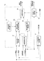
次に、図3、4を参照して、冷却ファンの故障検知を行う動作を説明する。図3は、図2に示す故障検知部6aが冷却ファンの故障検知を行う動作を示すフローチャートである。また、図4は、冷却ファン制御部68が故障検知処理を開始する指示を出す動作を示すフローチャートである。初めに図4を参照して、故障検知処理を開始する指示を出す動作について説明する。
【0026】
まず、冷却ファン制御部68はバッテリ3の温度を読み取る(ステップS11)。この温度は、バッテリ3を構成するモジュールに取り付けられた温度センサ19の出力が用いられる。
【0027】
次に、冷却ファン制御部68は、読み取ったバッテリ温度に応じて、冷却ファン18の風量を制御する。冷却ファン制御部68内には、バッテリ温度と冷却ファンの風量の関係が定義されたマップ(図示せず)が記憶されており、このマップを参照することによって、冷却ファン18の風量を決定し、この決定された風量を識別できる信号を冷却ファン18に対して出力する。これを受けて、冷却ファン18は、冷却ファン制御部68から出力された信号に基づいて風量を切り換える。また、同時に冷却ファン制御部68は、冷却ファンが動作する条件(ここでは、冷却ファン18が「Hi」または「Lo」の状態のこと)を満たしているか否かを判定する(ステップS12)。
【0028】
この判定の結果、条件を満たしていなければ、ステップS11へ戻り、条件を満たすまで繰り返す。一方、冷却ファン18が動作する条件を満たしている場合、冷却ファン制御部68は、モータ制御装置5から出力されるパワーセーブ情報を読み取る(ステップS13)。ここでいうパワーセーブとは、バッテリ3の温度が上昇して、これ以上充放電を繰り返すと充放電の効率が悪化し、さらなる温度上昇が発生するために、モータ2の使用を制限することである。パワーセーブ情報は、このパワーセーブが実施されている状態であるか否かを示す情報であり、モータ制御装置5より出力される。
【0029】
次に、冷却ファン制御部68は、パワーセーブ情報に基づいて、故障検知を開始する条件であるか(ここではパワーセーブが実施されているか)否かを判定する(ステップS14)。この判定の結果、読み取ったパワーセーブ情報がパワーセーブを実施していることを示す情報でない場合はステップS11へ戻り、処理を繰り返す。一方、パワーセーブが実施されている場合、冷却ファン制御部68は、故障判定部66へ故障検知を開始するように指示を出す(ステップS15)。
【0030】
このように冷却ファン制御部68は、バッテリ温度及びパワーセーブ情報に基づいて、故障検知を行うか否かを決定する。
【0031】
次に、図3を参照して、図2に示す故障検知部6aが冷却ファン18の故障を検知する動作を説明する。まず故障判定部66は、冷却ファン制御部68から故障検知の開始指示を読み取る(ステップS1)。続いて故障判定部66は、読み取った内容が故障検知を開始する指示であるか否かを判定する(ステップS2)。この判定の結果、通知された指示が故障検知開始を指示する内容でない場合、故障判定部66は、ステップS1へ戻り、開始指示が出されるまで待機する。
【0032】
一方、冷却ファン制御部68から故障検知を開始する指示が出された場合、故障判定部66は、故障が発生しているかを判定する処理を開始する。故障判定部66は、冷却ファン制御部68から故障検知開始指示が出されている間だけ冷却ファン18が故障しているか否かを示す故障検知結果を出力する。この故障検知結果は以下に説明する動作によって出力される。
【0033】
まず、入出力電力算出部61は、バッテリ3の電圧と充放電電流を読み取り、バッテリ3の入出力電力を算出する(ステップS3)。入出力電力は、電圧と電流を乗算することによって算出される。ただし、ここで算出される入出力電力は、所定時間内の平均電力である。ここでいう所定時間とは、例えば5分であり、図示しないタイマによって計測される。ここで算出される入出力電力は、バッテリ3の発熱量に相当する。バッテリ3が発する熱は、バッテリ3を出入りする電力に比例するため、ここでは、電力を算出することによってバッテリ3の発熱量を推定している。
【0034】
次に、温度差算出部62は、バッテリ3を冷却する冷媒の温度とバッテリ3の温度を読み込み、その温度差を算出する(ステップS4)。ここでいう冷媒とは、ハイブリッド車両内の空気であり、バッテリ3は、ハイブリッド車両内の空気によって冷却される。したがって、冷媒温度は車内に設けられた気温センサ(図示せず)の出力が用いられる。この気温センサの出力は、空調装置(エアコン)に備えられた気温センサの出力を利用するようにしてもよい。ここで算出される温度差は、現時点における冷却ファン18の冷却能力に相当する。冷却ファン18の能力は、冷却する対象(ここではバッテリ3)と冷媒の温度差が大きいほど冷却能力が高くなるため、ここでは、この温度差を算出することによって冷却ファン18の冷却能力を推定している。
【0035】
次に、実温度変化量算出部64は、所定時間内のバッテリ3の温度の変化量を算出する(ステップS5)。この変化量は、ステップS3において、平均電力を算出する場合に用いられたタイマによって計測された所定時間(ここでは、例えば5分とする)内のバッテリ3の温度変化量であり、この変化量を実温度変化量Tdと称する。
【0036】
次に、想定温度変化量算出部63は、入出力電力算出部61において算出された入出力電力と、温度差算出部62において算出された温度差とに基づいて、想定温度変化量マップ65を参照して、バッテリ3の想定温度変化量Tmを求める(ステップS6)。ここで参照される想定温度変化量マップ65は、バッテリ3の発熱量に相当する入出力電力と、冷却ファン18の冷却能力に相当する冷媒とバッテリ温度との温度差と、バッテリ3において想定される温度変化量Tmとの関係が定義されている。このマップを参照することによって、冷媒とバッテリ温度の差がある温度差であるときに、所定時間内にバッテリ3に対してある電力を出入りさせると、どれだけバッテリ温度が変化するかを示す想定温度変化量Tmを得ることができる。
【0037】
次に、故障判定部66は、想定温度変化量算出部63において求められた想定温度変化量Tmと実温度変化量算出部64において求められた実温度変化量Tdを比較する(ステップS7)。この判定の結果、実温度変化量Tdが想定温度変化量Tmより大きい値である場合、故障判定部66は、冷却ファン18が故障していると判断し、故障検知結果をモータ制御装置5へ通知する(ステップS8)。ただし、この故障検知結果がモータ制御装置5へ通知されるのは、冷却ファン制御部68から故障検知開始指示が出されている間だけである。一方、実温度変化量Tdが想定温度変化量Tmより大きい値でない場合、故障判定部66は、冷却ファン18は異常なしと判断し、その旨をモータ制御部5へ通知する。
【0038】
この通知を受けて、モータ制御装置5は、冷却ファン18が故障している場合、車両の運転者に対して、警告を発するとともに、モータ2の使用を制限する。これによって、ハイブリッド車両は、エンジン1のみで走行することとなる。ただし、バッテリ3の温度が十分に低い範囲である場合のみ充放電を許可するようにしてもよい。
【0039】
このように、バッテリの発熱量と冷却ファンの冷却能力と温度変化量とからなる想定温度変化量マップを備え、発熱量と冷却能力とに基づき想定温度変化量マップを参照して想定温度変化量を算出するようにしたため、想定温度変化量算出手段における演算処理を簡単にすることができ、想定温度変化量を高速に算出することができるという効果が得られる。さらに、想定温度変化量マップには、正常な状態である時のバッテリに対する入出力電力に応じた温度変化量が定義されているため、何らかの原因によってバッテリに異常な温度上昇が発生した状態も検知することができる。
【0040】
なお、故障検知部6aでは、図3のステップS3〜S5に示す処理が常に動作しており、冷却ファン制御部68から故障検知開始指示が出された時点の故障検知結果を出力する。このようにすることによって、冷却ファン18が故障しているにもかかわらず、故障検知に要する時間内にバッテリ3の充放電が行われることを防止することができる。
【0041】
また、バッテリ3を構成するモジュールに取り付けられる温度センサは全てのモジュールに取り付けるのではなく、冷却ファン18の冷却効果を最も受けやすい位置に配置されているモジュールに取り付けるようにしてもよい。
【0042】
また、想定温度変化量算出部63は、バッテリ3の入出力電力と冷媒とバッテリの温度差に基づいて、直接演算によって想定温度変化量Tmを算出するようにしてもよい。このようにすることによって、想定温度変化量マップ65を記憶しておく必要がないために、故障検知部6aの記憶容量の規模を小さくすることができる。
【0043】
また、想定温度変化量マップ65を備えた構成とする場合、このマップに記憶する値は、演算によって予め算出した値または、実測した値を用いるようにする。さらに、想定温度変化量算出部63は、バッテリ3の発熱量に相当する入出力電力から想定温度変化量を求めるようにして、故障判定部66は、この想定温度変化量と実温度変化量とによって故障検知を行うようにしてもよい。これは、パワーセーブが実施されるバッテリ温度が車内の気温より十分に高い場合に適用することができる。
【0044】
すなわち、故障検知が行われるバッテリ温度が気温より十分に高い場合、冷却ファン18によって冷却がされていれば、入出力電力に応じた温度上昇の割合が冷却されていない場合に比べて小さくなるはずであり、この温度上昇の割合を予め求めておき、この割合に近い温度上昇が発生しているか否かによって故障判定を行えばよい。このとき、想定温度変化量マップは、バッテリ3の発熱量に相当する入出力電力と想定温度変化量との2次元マップとすればよい。このようにすることによって、冷媒温度を測定する必要がなくなり、故障判定の処理を簡単にすることができる。
【0045】
このように、バッテリ制御装置6内においてバッテリ残容量を算出するために必要なセンサ出力のみを用いて、冷却ファン18の故障検知を行うようにしたため、故障検知を行うために新たにセンサ等を設けることなく故障検知を行うことができる。また、冷却ファン18の故障検知の結果に応じて、モータ2の使用を制限するようにしたため、バッテリ3のさらなる温度上昇を抑え、バッテリの劣化を防止することができる。
【0046】
【発明の効果】
以上説明したように、この発明によれば、バッテリの発熱量と冷却ファンの冷却能力とからバッテリの想定温度変化量を算出する想定温度変化量算出手段と、バッテリの実温度変化量を算出する実温度変化量算出手段と、想定温度変化量算出部において算出された想定温度変化量と実温度変化量算出部において算出された実温度変化量とを比較した結果に基づいて冷却ファンの故障を検知する故障判定手段とを備え、既に備えられているセンサ出力に基づき演算処理によって冷却ファンの故障を検知するようにしたため、新たに故障検知に必要なセンサ類を設けることなく冷却ファンの故障を検知することができるという効果が得られる。また、バッテリ温度の変化量に基づいて故障の判定を行うようにしたため、吸気口や排気口が塞がれることにより冷却能力が低下したことも検知することができるという効果も得られる。
【図面の簡単な説明】
【図1】ハイブリッド車両の制御装置の構成を示すブロック図である。
【図2】図1に示すバッテリ制御装置6の構成を示すブロック図である。
【図3】図2に示す故障検知部6aの動作を示すフローチャートである。
【図4】図2に示す冷却ファン制御部68の動作を示すフローチャートである。
【符号の説明】
1・・・エンジン、
2・・・モータ、
3・・・バッテリ、
6・・・バッテリ制御装置、
61・・・入出力電力算出部、
62・・・温度差算出部、
63・・・想定温度変化量算出部、
64・・・実温度変化量算出部、
65・・・想定温度変化量マップ、
66・・・故障判定部、
67・・・バッテリ残容量算出部、
68・・・冷却ファン制御部。[0001]
TECHNICAL FIELD OF THE INVENTION
The present invention relates to a cooling fan failure detection device that cools a battery mounted on a hybrid vehicle.
[0002]
[Prior art]
2. Description of the Related Art Conventionally, a hybrid vehicle provided with a motor in addition to an engine as a power source for traveling has been known. Hybrid vehicles include series hybrid vehicles and parallel hybrid vehicles. A series hybrid vehicle is a vehicle in which a motor is driven by using a power output of a generator driven by an engine or the like, and wheels are driven by the motor.
Therefore, since the engine and the wheels are not mechanically connected, the engine can be operated at a substantially constant speed in a high fuel consumption and low emission rotation speed region, and a better fuel efficiency and lower emission than the conventional engine vehicle can be obtained. realizable.
[0003]
On the other hand, in a parallel hybrid vehicle, a motor connected to the engine assists the drive shaft of the engine, and the electric energy obtained by using the motor as a generator is charged in a power storage device. The electrical energy is also used for electrical components in vehicles.
Therefore, since the driving load of the engine can be reduced, better fuel economy and lower emission can be realized as compared with the conventional engine vehicle.
[0004]
In the parallel hybrid vehicle, a motor that assists the output of the engine is directly connected to the output shaft of the engine, and this motor functions as a generator during deceleration or the like to store power in a battery or the like. Alternatively, there is a type in which a driving force can be generated by both, and a generator is separately provided.
In such a hybrid vehicle, various controls are performed such as, for example, assisting the output of the engine by a motor during acceleration and charging a battery or the like by deceleration regeneration during deceleration. (Hereinafter referred to as the remaining battery capacity) to meet the driver's requirements.
[0005]
[Problems to be solved by the invention]
By the way, a battery used in a hybrid vehicle has a temperature at which the charging efficiency sharply decreases when the temperature of the battery itself increases. This temperature is a temperature determined in advance by the performance of the battery. Even if charging is performed in a state where the temperature of the battery exceeds this temperature, only charging is converted into heat, and the charged power cannot be stored in the battery. Further, if charging and discharging are performed in a state where the temperature of the battery is high, a further rise in temperature occurs, which deteriorates the battery. For this reason, the battery mounted on the vehicle is provided with a cooling fan for cooling the battery itself, so that the battery temperature is maintained at a temperature lower than a temperature at which the charging efficiency sharply decreases.
[0006]
However, if the battery is charged and discharged without knowing that the cooling fan has failed for some reason, the temperature of the battery rises remarkably, and the deterioration of the battery is accelerated. Therefore, a device that detects that the cooling fan has failed is required. However, in order to detect the failure of the cooling fan, it is necessary to newly provide a sensor for detecting the failure, a failure detection circuit, and the like, and there is a problem that the cost is increased and the vehicle weight is increased. In addition, there is a problem that it is difficult to detect that the cooling capacity has been reduced by the electrical detection method such as the disconnection short-circuit detection because the intake port and the exhaust port of the refrigerant are blocked for some reason.
[0007]
The present invention has been made in view of such circumstances, and provides a cooling fan failure detection device for a hybrid vehicle that can detect a failure of a cooling fan without newly providing a failure detection circuit or a sensor. is there.
[0008]
[Means for Solving the Problems]
According to the first aspect of the present invention, an engine that outputs a propulsive force of a vehicle (for example, the
[0009]
According to the first aspect of the present invention, the assumed temperature change amount calculating means for calculating the assumed temperature change amount of the battery from the heat generation amount of the battery and the cooling capacity of the cooling fan, and the actual temperature change amount for calculating the actual temperature change amount of the battery. Detecting a cooling fan failure based on a result of comparing the assumed temperature change amount calculated by the assumed temperature change amount calculation unit with the actual temperature change amount calculated by the actual temperature change amount calculation unit; And a failure judging means for detecting the failure of the cooling fan by arithmetic processing based on the sensor output already provided, so that the failure of the cooling fan can be detected without newly providing sensors necessary for failure detection. The effect is obtained. Further, since the failure is determined based on the amount of change in the battery temperature, it is also possible to detect that the cooling capacity has been reduced due to the blockage of the intake port and the exhaust port.
Further, in the invention according to
[0010]
BEST MODE FOR CARRYING OUT THE INVENTION
Hereinafter, a control device for a hybrid vehicle according to an embodiment of the present invention will be described with reference to the drawings.
FIG. 1 is a block diagram showing the overall configuration of a parallel hybrid vehicle, which is a type of hybrid vehicle according to one embodiment of the present invention. In this figure,
[0011]
In the following description, when simply referred to as the battery temperature, it refers to the temperature of the maximum output value among the temperature sensors attached to each of the modules.
[0012]
The
[0013]
[0014]
[0015]
As described above, the
[0016]
Next, the operation of each control device of the hybrid vehicle having the above configuration will be briefly described.
First, the
The
[0017]
When the
[0018]
Next, when receiving the actual torque from the
The
[0019]
Next, the configuration of the
[0020]
The outputs of the
[0021]
Next, the operation of the
[0022]
Further, since the change in the voltage of the
[0023]
Further, the remaining battery
[0024]
Next, an operation for controlling the cooling
[0025]
Next, an operation for detecting a failure of the cooling fan will be described with reference to FIGS. FIG. 3 is a flowchart showing an operation in which the failure detection unit 6a shown in FIG. 2 performs failure detection of the cooling fan. FIG. 4 is a flowchart illustrating an operation in which the cooling
[0026]
First, the cooling
[0027]
Next, the cooling
[0028]
As a result of this determination, if the condition is not satisfied, the process returns to step S11, and is repeated until the condition is satisfied. On the other hand, if the condition for operating the cooling
[0029]
Next, based on the power save information, the cooling
[0030]
As described above, the cooling
[0031]
Next, with reference to FIG. 3, an operation in which the failure detection unit 6a shown in FIG. 2 detects a failure of the cooling
[0032]
On the other hand, when an instruction to start failure detection is issued from the cooling
[0033]
First, the input / output
[0034]
Next, the temperature
[0035]
Next, the actual temperature change
[0036]
Next, the assumed temperature change
[0037]
Next, the
[0038]
In response to the notification, when the cooling
[0039]
As described above, the estimated temperature change map including the heat generation amount of the battery, the cooling capacity of the cooling fan, and the temperature change amount is provided, and the estimated temperature change amount is referred to based on the heat generation amount and the cooling capacity. Is calculated, the calculation process in the assumed temperature change amount calculating means can be simplified, and the effect that the assumed temperature change amount can be calculated at a high speed can be obtained. In addition, since the assumed temperature change map defines the temperature change corresponding to the input / output power to the battery when it is in a normal state, it is possible to detect the state where an abnormal temperature rise has occurred in the battery for some reason. can do.
[0040]
In addition, in the failure detection unit 6a, the processing shown in steps S3 to S5 in FIG. 3 is always operating, and outputs a failure detection result at the time when the failure detection start instruction is issued from the cooling
[0041]
Further, the temperature sensors attached to the modules constituting the
[0042]
Further, the assumed temperature change
[0043]
Further, when the configuration is provided with the assumed temperature
[0044]
That is, when the battery temperature at which the failure detection is performed is sufficiently higher than the air temperature, if the cooling is performed by the cooling
[0045]
As described above, the failure detection of the cooling
[0046]
【The invention's effect】
As described above, according to the present invention, the assumed temperature change amount calculating means for calculating the assumed temperature change amount of the battery from the heat generation amount of the battery and the cooling capacity of the cooling fan, and the actual temperature change amount of the battery are calculated. An actual temperature change amount calculating unit, based on a result of comparing the assumed temperature change amount calculated by the assumed temperature change amount calculation unit with the actual temperature change amount calculated by the actual temperature change amount calculation unit, to determine a failure of the cooling fan; And a failure determination means for detecting the failure of the cooling fan by arithmetic processing based on the sensor output already provided, so that the failure of the cooling fan can be detected without newly providing sensors necessary for failure detection. The effect of being able to detect is obtained. Further, since the failure is determined based on the amount of change in the battery temperature, it is also possible to detect that the cooling capacity has been reduced due to the blockage of the intake port and the exhaust port.
[Brief description of the drawings]
FIG. 1 is a block diagram showing a configuration of a control device for a hybrid vehicle.
FIG. 2 is a block diagram showing a configuration of a
FIG. 3 is a flowchart showing an operation of a failure detection unit 6a shown in FIG.
4 is a flowchart showing an operation of a cooling
[Explanation of symbols]
1 ... engine,
2 ... motor,
3 ... battery,
6 ... Battery control device,
61 ... input / output power calculation unit,
62 ... temperature difference calculation unit,
63: assumed temperature change amount calculation unit
64: actual temperature change amount calculation unit,
65: assumed temperature change amount map,
66 ··· Failure determination unit
67 ... battery remaining capacity calculation unit
68 ... Cooling fan control unit.
Claims (2)
前記冷却ファン故障検知装置は、
前記冷却ファンの冷却能力を算出する冷却能力算出手段と、
前記バッテリの発熱量を算出するバッテリ発熱量算出手段と、
前記発熱量と前記冷却能力とから前記バッテリの想定温度変化量を算出する想定温度変化量算出手段と、
前記バッテリの実温度変化量を算出する実温度変化量算出手段と、
前記想定温度変化量算出部において算出された想定温度変化量と実温度変化量算出部において算出された実温度変化量とを比較した結果に基づいて前記冷却ファンの故障を検知する故障判定手段と、
を備え、
前記故障判定手段が前記冷却ファンを故障と判断した場合には、前記モータの使用を制限して、前記エンジンのみで走行する制御を行うことを特徴とする冷却ファン故障検知装置。An engine that outputs the propulsion force of the vehicle, a motor that generates an auxiliary driving force that assists the output of the engine, and a power supply that supplies power to the motor and operates the motor as a generator when no auxiliary driving force is required. A cooling fan failure detection device for a hybrid vehicle including a battery that charges the electrical energy obtained and a cooling fan that cools the battery,
The cooling fan failure detection device,
Cooling capacity calculating means for calculating the cooling capacity of the cooling fan,
Battery calorific value calculating means for calculating the calorific value of the battery;
Assumed temperature change amount calculating means for calculating an assumed temperature change amount of the battery from the heat generation amount and the cooling capacity,
An actual temperature change amount calculating means for calculating an actual temperature change amount of the battery,
Failure determination means for detecting a failure of the cooling fan based on a result of comparing the estimated temperature change calculated by the assumed temperature change calculator and the actual temperature change calculated by the actual temperature change calculator. ,
Equipped with a,
A cooling fan failure detection device, wherein when the failure determination unit determines that the cooling fan has failed, the use of the motor is limited and control for running only with the engine is performed .
Priority Applications (3)
| Application Number | Priority Date | Filing Date | Title |
|---|---|---|---|
| JP26123999A JP3566147B2 (en) | 1999-09-14 | 1999-09-14 | Hybrid vehicle cooling fan failure detection device |
| US09/661,286 US6377880B1 (en) | 1999-09-14 | 2000-09-13 | Cooling fan failure detection apparatus for hybrid vehicle |
| DE2000145426 DE10045426B4 (en) | 1999-09-14 | 2000-09-14 | Cooling fan fault detection device for a hybrid vehicle |
Applications Claiming Priority (1)
| Application Number | Priority Date | Filing Date | Title |
|---|---|---|---|
| JP26123999A JP3566147B2 (en) | 1999-09-14 | 1999-09-14 | Hybrid vehicle cooling fan failure detection device |
Publications (2)
| Publication Number | Publication Date |
|---|---|
| JP2001086601A JP2001086601A (en) | 2001-03-30 |
| JP3566147B2 true JP3566147B2 (en) | 2004-09-15 |
Family
ID=17359081
Family Applications (1)
| Application Number | Title | Priority Date | Filing Date |
|---|---|---|---|
| JP26123999A Expired - Fee Related JP3566147B2 (en) | 1999-09-14 | 1999-09-14 | Hybrid vehicle cooling fan failure detection device |
Country Status (3)
| Country | Link |
|---|---|
| US (1) | US6377880B1 (en) |
| JP (1) | JP3566147B2 (en) |
| DE (1) | DE10045426B4 (en) |
Families Citing this family (61)
| Publication number | Priority date | Publication date | Assignee | Title |
|---|---|---|---|---|
| JP4872143B2 (en) * | 2000-05-01 | 2012-02-08 | トヨタ自動車株式会社 | Cooling device for secondary battery |
| US20020163198A1 (en) * | 2001-05-03 | 2002-11-07 | Gee Thomas Scott | Fail-safe engine cooling control algorithm for hybrid electric vehicle |
| JP2002343449A (en) * | 2001-05-16 | 2002-11-29 | Nissan Motor Co Ltd | Failure determination device for cooling device |
| JP3638263B2 (en) * | 2001-09-10 | 2005-04-13 | 本田技研工業株式会社 | Vehicle drive device |
| JP4030929B2 (en) * | 2003-07-22 | 2008-01-09 | 本田技研工業株式会社 | Output control device for power storage device |
| JP2005160132A (en) * | 2003-11-20 | 2005-06-16 | Toyota Motor Corp | Device for determining abnormality of cooler |
| JP2005287136A (en) * | 2004-03-29 | 2005-10-13 | Honda Motor Co Ltd | Precharger of smoothing capacitor |
| US7484377B2 (en) * | 2004-07-30 | 2009-02-03 | Continental Automotive Systems Us, Inc. | Method and apparatus for cooling system failure detection |
| JP2006058325A (en) * | 2004-08-17 | 2006-03-02 | Murata Mach Ltd | Image forming apparatus |
| CA2557865C (en) | 2004-08-25 | 2009-10-13 | Toyota Jidosha Kabushiki Kaisha | Power supply device |
| JP2008517195A (en) * | 2004-10-15 | 2008-05-22 | ベール ゲーエムベーハー ウント コー カーゲー | Automotive fan system |
| JP4557756B2 (en) * | 2005-03-11 | 2010-10-06 | トヨタ自動車株式会社 | Electric motor cooling device and control method thereof, and abnormality determination method at the time of starting the cooling device |
| JP4772374B2 (en) * | 2005-04-27 | 2011-09-14 | プライムアースEvエナジー株式会社 | Battery pack device |
| US9104650B2 (en) | 2005-07-11 | 2015-08-11 | Brooks Automation, Inc. | Intelligent condition monitoring and fault diagnostic system for preventative maintenance |
| US7882394B2 (en) * | 2005-07-11 | 2011-02-01 | Brooks Automation, Inc. | Intelligent condition-monitoring and fault diagnostic system for predictive maintenance |
| JP5008863B2 (en) | 2005-11-30 | 2012-08-22 | プライムアースEvエナジー株式会社 | Secondary battery control device, secondary battery deterioration determination method using secondary battery temperature estimation method |
| JP4254783B2 (en) * | 2006-01-27 | 2009-04-15 | トヨタ自動車株式会社 | Hybrid control device |
| JP4773848B2 (en) * | 2006-03-03 | 2011-09-14 | プライムアースEvエナジー株式会社 | Secondary battery charge / discharge control system, battery control device, and program |
| US7735331B2 (en) * | 2006-09-20 | 2010-06-15 | Ford Global Technologies, Llc | System and method for controlling temperature of an energy storage device in a vehicle |
| JP5033385B2 (en) | 2006-09-27 | 2012-09-26 | 日立ビークルエナジー株式会社 | Power storage device |
| JP5369371B2 (en) * | 2006-10-03 | 2013-12-18 | 日産自動車株式会社 | Failure diagnosis device for battery cooling system |
| US8234025B2 (en) * | 2006-11-28 | 2012-07-31 | GM Global Technology Operations LLC | Control system for a hybrid powertrain system |
| JP4434199B2 (en) | 2006-12-14 | 2010-03-17 | トヨタ自動車株式会社 | Cooling device for electric equipment, cooling method, program for causing computer to realize cooling method, and recording medium recording the program |
| JP2008230281A (en) * | 2007-03-16 | 2008-10-02 | Honda Motor Co Ltd | Hybrid vehicle |
| US20080297136A1 (en) * | 2007-05-30 | 2008-12-04 | Ford Global Technologies, Llc | System and method to detect, in a vehicle, blockage of an airflow passage to a power storage unit |
| JP5178094B2 (en) * | 2007-08-27 | 2013-04-10 | キヤノン株式会社 | Battery, control method, and program |
| US7789794B2 (en) * | 2007-10-23 | 2010-09-07 | Ford Global Technologies, Llc | Method and system for controlling a propulsion system of an alternatively powered vehicle |
| US20100148708A1 (en) * | 2008-12-11 | 2010-06-17 | Jorgenson Joel A | Voltage scaling of an electric motor load to reduce power consumption |
| EP2404802A1 (en) * | 2009-03-06 | 2012-01-11 | Toyota Jidosha Kabushiki Kaisha | Hybrid vehicle control device and control method |
| MX2012008536A (en) * | 2010-01-21 | 2012-11-06 | Epower Engine Systems L L C | Hydrocarbon fueled-electric series hybrid propulsion systems. |
| JP5378264B2 (en) * | 2010-02-19 | 2013-12-25 | 富士重工業株式会社 | Electric vehicle inverter cooling system |
| US20110165829A1 (en) * | 2010-02-25 | 2011-07-07 | Ford Global Technologies, Llc | Automotive vehicle and method for operating climate system of same |
| JP2012164472A (en) * | 2011-02-04 | 2012-08-30 | Mitsubishi Heavy Ind Ltd | Cooling mechanism of battery system |
| PL2530273T3 (en) * | 2011-06-01 | 2020-11-16 | Joseph Vögele AG | Construction machine with automatic ventilator rotation speed regulator |
| JP5699880B2 (en) * | 2011-09-21 | 2015-04-15 | トヨタ自動車株式会社 | Battery cooling system |
| JP5770649B2 (en) * | 2012-01-27 | 2015-08-26 | 日野自動車株式会社 | Abnormality detection apparatus, hybrid vehicle, abnormality detection method, and program |
| US10744901B2 (en) * | 2012-06-13 | 2020-08-18 | Ford Global Technologies, Llc | Cooling system having active cabin venting for a vehicle battery |
| US20140012459A1 (en) * | 2012-07-05 | 2014-01-09 | BlueRadios, Inc. | System And Method To Instrument And Gather Three Dimensional (3-D) Vehicle Tracking And Information |
| US9168844B2 (en) * | 2012-07-30 | 2015-10-27 | GM Global Technology Operations LLC | Methods and systems for diagnosing performance of active cooling system in an electric vehicle |
| US9300017B2 (en) * | 2012-08-03 | 2016-03-29 | Ford Global Technologies, Llc | Detecting blockage of air flow through vehicle traction battery |
| JP6081130B2 (en) * | 2012-10-12 | 2017-02-15 | 日野自動車株式会社 | On-vehicle power control device cooling system and abnormality diagnosis method |
| JP5776735B2 (en) * | 2013-07-04 | 2015-09-09 | 株式会社デンソー | Battery temperature control device |
| US9448131B2 (en) * | 2013-08-27 | 2016-09-20 | Ford Global Technologies, Llc | Battery pack leak detection assembly and method |
| US10086718B2 (en) * | 2013-10-15 | 2018-10-02 | Ford Global Technologies, Llc | System and method for operating a battery pack |
| JP6187309B2 (en) * | 2014-02-21 | 2017-08-30 | トヨタ自動車株式会社 | Electric vehicle power supply device |
| JP5877856B2 (en) * | 2014-03-03 | 2016-03-08 | ファナック株式会社 | Numerical control device with heat dissipation characteristic estimation unit |
| US20150291054A1 (en) * | 2014-04-15 | 2015-10-15 | Ford Global Technologies, Llc | Traction Battery Air Thermal Management Control System |
| US10059222B2 (en) * | 2014-04-15 | 2018-08-28 | Ford Global Technologies, Llc | Battery temperature estimation system |
| JP6299549B2 (en) * | 2014-09-29 | 2018-03-28 | トヨタ自動車株式会社 | Battery cooling system |
| FR3042314B1 (en) * | 2015-10-07 | 2021-05-14 | Renault Sas | METHOD OF DETECTION OF A THERMAL INTERFACE FAULT BETWEEN A BATTERY AND ITS THERMAL CONDITIONING SYSTEM |
| JP6210105B2 (en) * | 2015-11-04 | 2017-10-11 | トヨタ自動車株式会社 | Battery device |
| JP6790614B2 (en) * | 2016-09-06 | 2020-11-25 | トヨタ自動車株式会社 | Charge / discharge control system for secondary batteries |
| JP6790729B2 (en) * | 2016-11-01 | 2020-11-25 | トヨタ自動車株式会社 | In-vehicle battery cooling system |
| DE102018206487A1 (en) * | 2018-04-26 | 2019-10-31 | Robert Bosch Gmbh | Method for determining a state of the thermal connection of at least one component within an electrical energy storage system to a heat source or heat sink |
| DE102018220045A1 (en) * | 2018-11-22 | 2020-05-28 | Robert Bosch Gmbh | Method for determining a state of a thermal management system of an electrical energy store and corresponding device, corresponding electrical energy store, corresponding computer program and corresponding machine-readable storage medium |
| JP7292908B2 (en) * | 2019-03-13 | 2023-06-19 | 株式会社東芝 | Abnormality detection device, abnormality detection method, and program |
| CN112103593A (en) * | 2019-06-17 | 2020-12-18 | 比亚迪股份有限公司 | Vehicle thermal management method and device, vehicle and storage medium |
| JP7435201B2 (en) * | 2020-04-21 | 2024-02-21 | マツダ株式会社 | temperature control device |
| JP7359105B2 (en) * | 2020-08-12 | 2023-10-11 | トヨタ自動車株式会社 | Air blower system abnormality diagnosis device |
| CN113135117B (en) * | 2021-03-29 | 2023-02-10 | 广州小鹏汽车科技有限公司 | Cooling system detection method and device, vehicle and storage medium |
| JPWO2023120054A1 (en) * | 2021-12-21 | 2023-06-29 |
Family Cites Families (10)
| Publication number | Priority date | Publication date | Assignee | Title |
|---|---|---|---|---|
| DE4018347A1 (en) * | 1990-06-08 | 1991-12-12 | Audi Ag | ARRANGEMENT FOR COOLING THE BATTERY OF A MOTOR VEHICLE |
| JP3125198B2 (en) * | 1991-12-04 | 2001-01-15 | 本田技研工業株式会社 | Battery temperature control device for electric vehicle |
| DE4433836C1 (en) * | 1994-09-22 | 1995-11-09 | Daimler Benz Ag | Device for heating an interior of an electric vehicle |
| US5620057A (en) * | 1994-12-19 | 1997-04-15 | General Motors Corporation | Electric vehicle battery enclosure |
| DE19500897A1 (en) * | 1995-01-13 | 1996-07-18 | Plasto Textil Gmbh | Drive belt |
| JP3116781B2 (en) * | 1995-09-11 | 2000-12-11 | トヨタ自動車株式会社 | Radiator cooling fan system abnormality detector |
| US6186254B1 (en) * | 1996-05-29 | 2001-02-13 | Xcelliss Fuel Cell Engines Inc. | Temperature regulating system for a fuel cell powered vehicle |
| US6009362A (en) * | 1996-08-29 | 1999-12-28 | Nissan Motor Co., Ltd. | Anomalous condition detecting apparatus for cooling motor fan |
| JP3240973B2 (en) * | 1997-03-05 | 2001-12-25 | トヨタ自動車株式会社 | Battery cooling system for vehicles |
| JP4069484B2 (en) * | 1998-02-02 | 2008-04-02 | 株式会社デンソー | Vehicle fan failure diagnosis device |
-
1999
- 1999-09-14 JP JP26123999A patent/JP3566147B2/en not_active Expired - Fee Related
-
2000
- 2000-09-13 US US09/661,286 patent/US6377880B1/en not_active Expired - Lifetime
- 2000-09-14 DE DE2000145426 patent/DE10045426B4/en not_active Expired - Fee Related
Also Published As
| Publication number | Publication date |
|---|---|
| DE10045426A1 (en) | 2001-05-31 |
| JP2001086601A (en) | 2001-03-30 |
| US6377880B1 (en) | 2002-04-23 |
| DE10045426B4 (en) | 2008-03-27 |
Similar Documents
| Publication | Publication Date | Title |
|---|---|---|
| JP3566147B2 (en) | Hybrid vehicle cooling fan failure detection device | |
| JP3857146B2 (en) | Control device for hybrid vehicle | |
| JP3568840B2 (en) | Hybrid vehicle control device | |
| JP3926518B2 (en) | Battery control device for hybrid vehicle | |
| US7438984B2 (en) | Electric system for fuel cell, fuel cell vehicle, and method of supplying electric power | |
| US10381695B2 (en) | Cooling system for secondary battery | |
| JP3529680B2 (en) | Motor control device for hybrid vehicle | |
| JP4116609B2 (en) | Power supply control device, electric vehicle and battery control unit | |
| US6225784B1 (en) | Battery control apparatus for battery carried by hybrid vehicle | |
| US6329772B1 (en) | Control apparatus of hybrid vehicles | |
| JP5547699B2 (en) | Vehicle drive device | |
| JP2001065437A (en) | Control device for hybrid vehicle | |
| JPH05146008A (en) | Drive controller for series hybrid vehicle | |
| JP2010273417A (en) | Electric vehicle | |
| JPH09289042A (en) | Cooling device of battery for electric vehicle | |
| JP2002325373A (en) | Control device for battery capacity | |
| JP5436785B2 (en) | Power supply | |
| JP3152122B2 (en) | Battery cooling device | |
| JP2008189236A (en) | Control device of hybrid vehicle | |
| JPH09289701A (en) | Output controller of electric automobile | |
| JP2004281077A (en) | Cooling control device of battery pack | |
| US11695292B2 (en) | Power supply system for mobile body | |
| JP3730246B2 (en) | Control device and control method for hybrid vehicle | |
| JP2001103612A (en) | Fan controller of hybrid vehicle | |
| JP5237649B2 (en) | Vehicle power control device and secondary battery life determination device |
Legal Events
| Date | Code | Title | Description |
|---|---|---|---|
| TRDD | Decision of grant or rejection written | ||
| A01 | Written decision to grant a patent or to grant a registration (utility model) |
Free format text: JAPANESE INTERMEDIATE CODE: A01 Effective date: 20040601 |
|
| A61 | First payment of annual fees (during grant procedure) |
Free format text: JAPANESE INTERMEDIATE CODE: A61 Effective date: 20040609 |
|
| R150 | Certificate of patent or registration of utility model |
Free format text: JAPANESE INTERMEDIATE CODE: R150 |
|
| FPAY | Renewal fee payment (event date is renewal date of database) |
Free format text: PAYMENT UNTIL: 20080618 Year of fee payment: 4 |
|
| FPAY | Renewal fee payment (event date is renewal date of database) |
Free format text: PAYMENT UNTIL: 20090618 Year of fee payment: 5 |
|
| FPAY | Renewal fee payment (event date is renewal date of database) |
Free format text: PAYMENT UNTIL: 20090618 Year of fee payment: 5 |
|
| FPAY | Renewal fee payment (event date is renewal date of database) |
Free format text: PAYMENT UNTIL: 20100618 Year of fee payment: 6 |
|
| FPAY | Renewal fee payment (event date is renewal date of database) |
Free format text: PAYMENT UNTIL: 20110618 Year of fee payment: 7 |
|
| FPAY | Renewal fee payment (event date is renewal date of database) |
Free format text: PAYMENT UNTIL: 20110618 Year of fee payment: 7 |
|
| FPAY | Renewal fee payment (event date is renewal date of database) |
Free format text: PAYMENT UNTIL: 20130618 Year of fee payment: 9 |
|
| FPAY | Renewal fee payment (event date is renewal date of database) |
Free format text: PAYMENT UNTIL: 20130618 Year of fee payment: 9 |
|
| FPAY | Renewal fee payment (event date is renewal date of database) |
Free format text: PAYMENT UNTIL: 20140618 Year of fee payment: 10 |
|
| LAPS | Cancellation because of no payment of annual fees |