JP3557728B2 - Data recording / reproducing apparatus and method, and disk-shaped recording medium - Google Patents
Data recording / reproducing apparatus and method, and disk-shaped recording medium Download PDFInfo
- Publication number
- JP3557728B2 JP3557728B2 JP17681695A JP17681695A JP3557728B2 JP 3557728 B2 JP3557728 B2 JP 3557728B2 JP 17681695 A JP17681695 A JP 17681695A JP 17681695 A JP17681695 A JP 17681695A JP 3557728 B2 JP3557728 B2 JP 3557728B2
- Authority
- JP
- Japan
- Prior art keywords
- data
- bytes
- recording
- sector
- recording medium
- Prior art date
- Legal status (The legal status is an assumption and is not a legal conclusion. Google has not performed a legal analysis and makes no representation as to the accuracy of the status listed.)
- Expired - Fee Related
Links
Images


Classifications
-
- G—PHYSICS
- G11—INFORMATION STORAGE
- G11B—INFORMATION STORAGE BASED ON RELATIVE MOVEMENT BETWEEN RECORD CARRIER AND TRANSDUCER
- G11B20/00—Signal processing not specific to the method of recording or reproducing; Circuits therefor
- G11B20/10—Digital recording or reproducing
- G11B20/12—Formatting, e.g. arrangement of data block or words on the record carriers
- G11B20/1262—Formatting, e.g. arrangement of data block or words on the record carriers with more than one format/standard, e.g. conversion from CD-audio format to R-DAT format
Landscapes
- Engineering & Computer Science (AREA)
- Multimedia (AREA)
- Signal Processing (AREA)
- Signal Processing For Digital Recording And Reproducing (AREA)
Description
【0001】
【産業上の利用分野】
この発明は、異なるフォーマットのデータ記録媒体、特に、異なるセクタサイズのデータ記録媒体の間の信号処理を簡単化できるデータ記録/再生装置、および方法、並びにディスク状記録媒体に関する。
【0002】
【従来の技術】
コンピュータの外部記憶装置として、大容量、高速アクセスの利点から光ディスクドライブが注目され、既に、CD−ROM(またはCD−I(CD Interactive) )ドライブ、MO(イレーザブルディスクの一つである光磁気ディスク)ドライブの採用は、急速に拡がりつつある。これら以外にも、ディスク直径が2.5インチのMD(ミニディスク;イレーザブルディスク)も提案されている。さらに、映像記憶媒体として、DVD(ディジタル・ビデオ・ディスク)が開発されつつある。
【0003】
DVDは、CDと同一の直径の再生専用ディスク、またはMOディスクあるいは相変化型ディスクとされた記録/再生可能な光ディスクであって、MPEG等で圧縮した映像情報を再生、または記録/再生できるディスクである。DVDでは、レーザ光の短波長化の進展と、対物レンズのNAの増大と共に、ディジタル変調およびエラー訂正符号化の処理の改良によって、記録密度がより一層、向上され、単層ディスクの場合でも、データ記憶容量が約3.7Gバイトと膨大なものである。CD、MDが当初は、ディジタルオーディオディスクとして開発され、その後、コンピュータの外部記憶媒体としても利用されるのと同様に、より大容量のDVDもコンピュータの外部記憶媒体として利用されることが期待されている。
【0004】
従来では、磁気テープ、磁気ディスク、フレキシブルディスク、上述した光ディスク等の媒体毎に異なるフォーマットが規定されており、互換性についての考慮がされているとは言えなかった。そのため、新媒体と既存媒体との互換をとる場合には、論理的な領域でしか対応せず、効率的ではなかった。例えばコンピュータの外部記憶媒体の場合では、128バイト×2i のセクタサイズ(512バイト、2,048バイト(2Kバイト)等)が主流であるのに対して、CD−ROMは2,352バイト(同期信号を除いた場合には、2,340バイト、同期信号およびヘッダを除いた場合には、2,336バイト)を1ブロックとしており、物理的に両者が対応しにくい問題があった。
【0005】
【発明が解決しようとする課題】
上述したDVDは、CDと同様の読出し専用ディスク、記録可能なMOディスク、または相変化型ディスクでも実現できるものであり、その容量が既存の光ディスクの何れと比較しても、かなり大きいという利点がある。かかるDVDを新たに外部記憶媒体として利用する場合、既存の光ディスク媒体、特に、広範に普及しており、また、略同一のディスクサイズであり、さらに、同一の読み取り方式を採用するCD−ROMとの互換性を考慮することは、CD−ROMとDVDとの間のデータの相互乗り入れを簡単とし、また、ドライブの共用化を可能とし、さらに、CD−ROMの資産を活用するうえで不可欠なことである。
【0006】
従って、この発明の目的は、512バイトの整数倍の長さらのデータを含むセクタと、CDフォーマットに準ずるバイト長のデータからなるセクタとの何れにも対応することができるデータ記録/再生装置および方法、並びにディスク状記録媒体を提供することにある。
【0007】
【課題を解決するための手段】
上述の目的を達成するために、この発明は、データ記録媒体に対してディジタルデータを記録するようにしたデータ記録装置において、
データ部分が512バイトの整数倍の長さに区切られた第1のデータおよびデータ部分がCDフォーマットに準ずるバイト長に区切られた第2のデータを受け取るための入力手段と、
第1および第2のデータをセクタ構造に変換するためのフォーマット化手段と、
フォーマット化手段からのデータに対してエラー訂正符号化を行うためのエンコード手段と、
エラー訂正符号化されたデータをディジタル変調するための変調手段と、
変調手段からの記録データをデータ記録媒体に対して記録するための記録手段とからなることを特徴とするデータ記録装置である。また、この発明は、上述のようにデータを記録する記録方法である。
【0008】
また、この発明は、データ部分が512バイトの整数倍の長さに区切られた第1のデータおよびデータ部分がCDフォーマットに準ずるバイト長に区切られた第2のデータがセクタ構造に変換され、さらに、エラー訂正符号化およびディジタル変調の処理がされてなるデータが記録されたデータ記録媒体を再生するデータ再生装置において、
データ記録媒体からデータを再生するための手段と、
再生されたデータをディジタル復調するための手段と、
復調されたデータをエラー訂正するためのデコード手段と、
エラー訂正された第1のデータおよび第2のデータを送出するための手段とからなるデータ再生装置である。また、この発明は、上述のようにデータを再生する再生方法である。
【0010】
よりさらに、この発明は、データ部分が512バイトの整数倍の長さに区切られた第1のデータおよび第1のデータを識別する情報がエラー訂正符号化およびディジタル変調の処理がされて記録される第1の記録層と、データ部分がCDフォーマットに準ずるバイト長に区切られた第2のデータおよび第2のデータを識別する情報がエラー訂正符号化およびディジタル変調の処理がされて記録される第2の記録層とが単一のディスク内に各別に設けられたことを特徴とするデータ記録媒体である。
【0011】
【作用】
512バイトの整数倍例えば2,048バイトとCDフォーマットに準ずるバイト長例えば2,352バイトの長さのデータをそれぞれ有する二つのセクタに、物理的な領域で対応することが可能となり、同一の記録媒体上に、コンピュータストレージ用のデータとCD−ROM用のデータとを移植することができる。
【0012】
【実施例】
以下、この発明の一実施例について図面を参照して説明する。図1は、この発明による光ディスク記録システムを示し、図2は、光ディスク再生システムを示す。記録システムでは、入力端子1から記録データが供給され、これが光ディスク2に記録される。記録データは、圧縮されたビデオデータ、圧縮されたオーディオデータ、コンピュータ用のデータ等である。現在提案されているDVDの記録可能なタイプ(光磁気型あるいは相変化型のディスク)は、光ディスク2の一例である。なお、図1の記録システムは、記録可能な光ディスク2に対して適用されるのみならず、再生専用ディスクのマスタリングシステムに対しても適用できる。
【0013】
ここで、この発明を適用できる光ディスク2のデータ構造、特に、アクセス(記録または再生)のためのデータ単位について説明する。最初にCD−ROMデータのセクタ構造について説明する。CD−ROMは、周知のCDから発展したものである。CDは、図3に示すように、伝送フレーム(EFMフレーム、C1フレームとも称されることがある)内に、1バイトのサブコード、24バイトのデータ、各4バイトのC1パリティおよびC2パリティが配置されたものである。CD上には、EFM変調により各バイトが14チャンネルビットのコードワードに変換され、結合ビット(3チャンネルビット)を介して記録される。さらに、各伝送フレームの先頭に、11T(Tは、チャンネルビットの周期)の反転間隔が連続し、その後に2チャンネルビットが付加された計24チャンネルビットのシンク(同期信号を意味する)が付加される。
【0014】
サブコードは、98伝送フレームを周期として1単位となるように構成されている。従って、CD−DA(Digital Audio) では、98伝送フレーム内に、
24バイト×98=2,352バイト
のユーザデータが含まれる。また、サブコードまでを含めると、
25バイト×98=2,450バイト
となる。このように、CD−DAのフォーマットでは、2,352バイトと2,450バイトの2種類のデータサイズが存在する。
【0015】
このCDの伝送フォーマットに基づいてCD−ROMのデータ構造が規定されている。すなわち、CD−ROMは、サブコードの周期の98フレームに含まれるデータである、2,352バイトをアクセス単位とする。このアクセス単位は、ブロックとも称されるが、以下の記述では、セクタと称することにする。図4は、CD−ROMの1セクタのデータ構造を示す。
【0016】
CD−ROMでは、モード0、モード1、モード2が規定されている。これらのモードに共通して、セクタの区切りを示すシンク(12バイト)、ヘッダ(4バイト)が付加される。モード0は、これらのシンクおよびヘッダ以外が全て“0” のデータであり、ダミーデータとして使用される。図4は、モード1およびモード2の1セクタのデータ構造を示す。ヘッダは、CDのサブコードと同様の3バイトのアドレス情報と1バイトのモード情報とからなる。
【0017】
モード1のデータ構造では、ユーザデータが2,048(2K)バイトであり、エラー訂正能力を高めるために、288バイトの補助データが付加されている。すなわち、エラー検出符号(4バイト)、スペース(8バイト相当)、Pパリティ(172バイト)、Qパリティ(104バイト)が付加されている。モード1は、文字コード、コンピュータデータ等のように、信頼性が高いことが要求されるデータの記録に好適である。モード2は、288バイトの補助データが付加されず、従って、2,336バイトのユーザデータの記録が可能なモードである。モード2は、ビデオデータ、オーディオデータのようなエラーを補間できるデータの記録に適している。
【0018】
さらに、CD−ROMと同様の読出し専用ディスクとして、CD−Iが規格化されている。図5は、CD−Iの1セクタのデータ構造を示す。CD−ROMと同様に、12バイトのシンク、4バイトのヘッダを付加され、ヘッダ中のモード情報は、モード2とされる。ヘッダの後に、CD−Iでは、8バイトのサブヘッダが付加される。サブヘッダは、各2バイトのファイルナンバー、チャンネルナンバ、サブモード、データタイプからなる。
【0019】
さらに、CD−ROMのモード1とモード2と同様に、CD−Iでは、フォーム1および2が規定されている。フォーム1では、4バイトのエラー検出符号、172バイトのPパリティ、104バイトのQパリティが付加される。CD−ROMのモード1におけるスペースが存在せず、ユーザデータの領域が2,048バイトである。フォーム2では、リザーブ領域(4バイト)が設けられ、ユーザデータの領域が2,324バイトである。
【0020】
以上のように、CDフォーマットに準ずるバイト長としては、2,352バイトを基本として、付加的データ(ヘッダ、サブコード等)の扱いによって、2,340バイト、2,336バイト、または2,450バイトが存在しうる。
【0021】
次に、セクタ構造の他の例について説明すると、これは、図6Aに示すように、1セクタの2,048(=2K)バイトのユーザデータに対して、データシンク(4バイト)およびヘッダ(16バイト)が付加され、また、信頼性の向上のためのエラー検出符号EDC(4バイト)が付加されたものである。従って、1セクタの長さが2,072バイトである。
【0022】
図6Bは、ヘッダのデータをより詳細に示す。すなわち、ヘッダに対するエラー検出符号(具体的にはCRC)の2バイト、コピー可否を管理するための管理情報CGMSの1バイト、単層ディスクと多層ディスクとを識別するとともに、そのディスクに含まれる層数、データが記録されている層の番号を示すレイヤーの1バイト、アドレスの4バイト、補助的データの8バイトとからヘッダが構成される。この一実施例では、補助的データ中にセクタ構造を識別するためのセクタID信号が挿入される。
【0023】
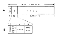
一方、上述したCD−ROM、CD−I、CD−DA等のCDフォーマットに準ずるデータは、例えば2,352バイトであるから、この部分をユーザデータとして、図7Aに示すように、データシンク(4バイト)およびヘッダ(12バイト)を付加する。従って、1セクタの長さが2,368バイトである。CD−DAの場合では、98伝送フレーム内に2,352バイトのユーザデータが含まれる。ヘッダは、図7Bに拡大して示すように、CRC(2バイト)、コピー管理情報CGMS、レイヤー、アドレス、および補助的データ(4バイト)からなる。補助的データの長さがより短くされていること以外は、図6Bに示すヘッダと同一の情報を図7Bのヘッダが有する。
【0024】
このように、1セクタの長さは、異なるものとなり、然も、整数比の関係にはない。この一実施例では、二つの異なるセクタサイズをAおよびBとするときに、nAとmB(n、mは、それぞれ整数で、n≠m、n>mである)が所定サイズのデータ単位(ブロックと称する)に入るように、ブロックを規定する。そして、ブロックの単位で、データを記録/再生(すなわち、アクセス)するものである。n、mの規定の方法には、nおよびmを互いに素に選ぶ。とくに、AおよびBのサイズが近い場合には、m=m−1で構成するように考える方法と、n=2j (jは自然数)で構成する方法がある。mおよびnを互いに素に規定する方法は、ブロックサイズを最小とする場合に採用される。n=2j と規定する方法は、コンピュータシステムとの親和性を考える場合に採用される。
【0025】
上述の例において、ユーザデータのみを考えると、n=8、m=7と規定すると、
2,048バイト×8=16,384バイト
2,336バイト×7=16,352バイト
となり、16Kバイト(16,384)バイトのブロックにおさまる。
【0026】
さらに、上述したように、データシンクおよびヘッダを付加したものをセクタサイズとして考えると、A´=2,072、B´=2,368であるから、n=8、m=7と選定し、ブロックサイズは、
2,072×8=2,368×7=16,576バイト
となり、共通の同一ブロックサイズを規定することができる。
【0027】
この場合の1ブロックのデータ構造として、図8に示すように、(148×112=16,576バイト)の2次元配列を規定し、この2次元配列に対してエラー訂正符号を適用することによって、エラー訂正能力を高くすることができる。エラー訂正符号としては、縦方向(各列)の162バイトに対して、第1のエラー訂正符号(C1符号と称する)の符号化を行い、8バイトをC1パリティを生成し、斜め方向の156バイトに対して、第2のエラー訂正符号(C2符号と称する)の符号化を行い、14バイトのC2パリティを付加する、畳み込み型の2重符号化を採用できる。
【0028】
勿論、エラー訂正符号としては、これ以外に、積符号、ブロック完結型の2重符号化、LDC(Long Distance Code)等を採用しても良く、単なるエラー検出符号による符号化を行なうことも可能である。
【0029】
2つの異なるサイズのセクタを同一サイズのブロックに統合する場合について、図9を参照してより具体的に説明する。図9Aは、図6Aに示すセクタサイズが2,072バイトのセクタ(以下、2Kバイトセクタと称する)の場合の処理を示す。この1セクタをR/W方向に148バイト毎に区切り、148×14=2,072バイトの2次元配列を形成する。従って、この配列の1セクタは、1ブロック内に8個含まれ、1ブロックが8セクタのデータ構造が形成される。
【0030】
図9Bは、図7Aに示すセクタサイズが2,368バイトのセクタ(以下、CDセクタと称する)の場合の処理を示す。この1セクタをR/W方向に148バイト毎に区切り、148×16=2,368バイトの2次元配列を形成する。従って、この配列の1セクタは、1ブロック内に7個含まれ、1ブロックが7セクタのデータ構造が形成される。記録/再生時には、データの2,072バイトまたは2,368バイトをカウントするカウンタを設け、7個または8個のセクタシンクを検出することによって、ブロックの区切りを決定する。この方法に限らず、セクタシンクと別のブロックシンクを付加しても良い。このブロックは、エラー訂正符号がブロック完結型の場合には、必要とされるが、この発明では、必須の事項ではない。
【0031】
上述の説明では、コンピュータからのデータの1セクタに2Kバイトのデータが含まれるものとしたが、512バイトの整数倍のデータがセクタに含まれれば良い。例えば512×2=1,024(=1K)バイトのデータを含むセクタ構造としては、図10Aに示すものを採用できる。このセクタには、1,024バイトのユーザデータ以外に、2バイトのデータシンク、8バイトのヘッダ、4バイトのエラー検出符号が含まれる。また、ヘッダは、図10Bに示すように、ヘッダのエラー検出のためのCRC(1バイト)、コピー管理情報CGMS(1バイト)、レイヤー情報(1バイト)、アドレス(4バイト)、補助的データ(1バイト)から構成される。各情報の意味は、上述したものと同様である。
【0032】
そして、この1Kバイトのセクタをブロック化する場合、A=1,024(=1K)バイト、A´を1,036バイトとすると、n=16、m=7で同様にブロック化することができる。すなわち、図11に示すように、R/W方向に148バイト毎に区切り、148×7=1,036バイトの2次元配列を形成し、16セクタによって、1ブロックのデータが形成される。
【0033】
図1に戻って、この発明の一実施例の記録システムについて説明する。入力端子1からのディジタルデータがインターフェース3例えばSCSIを介してスイッチ回路5aに供給され、スイッチ回路5aにより選択的にフォーマット化回路4a、4bに供給される。これらのフォーマット化回路4a、4bは、受け取ったディジタルデータをセクタ毎に区切り、データシンクおよびヘッダを付加する。すなわち、フォーマット化回路4aは、受け取ったデータを図6Aに示す2Kバイセクタのセクタ構造に変換し、フォーマット化回路4bは、受け取ったデータを図7Aに示すようなCDセクタのセクタ構造に変換する。
【0034】
スイッチ回路5aは、インターフェース3から出力されるID信号により制御され、インターフェース3が受け付けたデータと対応してスイッチ回路5aが切り替えられる。例えばコンピュータから2Kバイトで区切られたデータを受け取った場合では、ID信号によって、スイッチ回路5aがフォーマット化回路4aを選択する。一方、例えばCD−ROMドライブから2,352バイトで区切られたデータを受け取った場合では、スイッチ回路5aがフォーマット化回路4bを選択する。また、ID信号がフォーマット化回路4a、4bに供給され、各セクタのヘッダに対して、例えば補助的データの一部として、ID信号が挿入される。フォーマット化回路4a、4bの出力データがブロック化回路6に供給される。
【0035】
図1では示されていないが、ID信号をTOC発生回路に供給し、ID信号を含むTOCデータを生成しても良い。TOC(Table Of Contents) データは、ディスクのコントロール情報、ディレクトリ情報等を含み、例えば最内周トラックに記録されるデータであって、ディスクをドライブに装着した時にTOCデータが読み取られる。DIT(Disk Information Table)と称される場合もあるが、これもTOCデータと同様のものである。
【0036】
また、入力端子1に対して、ユーザデータのみならず、このTOCデータも供給し、TOCデータもユーザデータと共に、セクタ構造に変換しても良い。この場合、TOCデータからなるTOCセクタとユーザデータからなるユーザセクタとの関係としては、次のようなものが可能である。第1のデータ構造は、TOCセクタが2Kセクタであり、ユーザセクタが2KセクタまたはCDセクタのものである。第2のデータ構造は、TOCセクタがCDセクタであり、ユーザセクタがCDセクタのものである。これは、CD−ROMのデータの全体をそっくり光ディスク2に記録する場合に該当する。第3のものは、TOCセクタが2Kセクタの第1のTOCセクタと、CDセクタの第2のTOCセクタとからなり、ユーザセクタがCDセクタのものである。これは、CD−ROMのデータの全体をそっくり記録するとともに、光ディスク2(例えばDVD)のTOCデータを2Kセクタとして構成する場合に該当する。
【0037】
ブロック化回路6は、7セクタまたは8セクタからなるブロックを構成する。ブロック化回路6からのデータがエラー訂正符号のエンコーダ8に供給される。エンコーダ8は、図8に示すような畳み込み型の二重符号化のエラー訂正符号の符号化を行なう。エンコーダ8の具体的処理については後述する。
【0038】
エンコーダ8の出力がディジタル変調回路9に供給される。ディジタル変調回路9は、例えば1バイト(8ビット)のデータシンボルを16ビットのコードワードに、予め決めたテーブルに従ってマッピングすることによって、直流分の少ない変調出力を生成する。勿論、CDにおけるEFM、8ビットのデータシンボルを15ビットのコードワードに変換する8−15変調等をディジタル変調として採用することができる。ディジタル変調回路9の出力がスイッチ回路5bを介してシンク付加回路10a、10bに対して選択的に供給される。
【0039】
シンク付加回路10a、10bは、シンク信号(セクタシンク、付加的シンクS1、C1シンクS2、およびブロックシンク)を変調されたデータに対して付加する。この一実施例では、後述するように、これらの付加されるシンクのパターンを利用してセクタ構造を識別することを可能としている。シンク付加回路10aは、2Kバイトセクタのためのシンクをデータに付加し、シンク付加回路10bは、CDセクタのためのシンクをデータに付加する。これらのシンクとしては、変調されたデータ中に現れることがない、特異なビットパターンのものが使用される。
【0040】
シンク付加回路10a、10bの出力がドライバ11を介して光ピックアップ12に供給され、光磁気記録、または相変化によって光ディスク2に記録される。光ディスク2は、スピンドルモータ13によって、CLV(線速度一定)またはCAV(角速度一定)によって回転される。光ピックアップ12によって記録/再生されるデータの最小単位が上述の1ブロックである。
【0041】
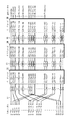
シンク付加回路10a、10bから出力される記録データについて図12を参照して説明する。図12Aは、2Kバイトセクタの記録データを示す。図12Aに示すように、1セクタ(2,072バイト)が148個のデータ毎に区切られ、このデータに対して畳み込み型の2重符号化によって、8バイトのパリティPおよび14バイトのパリティQが付加される。従って、(148+22=170)個のデータシンボルが生成される。このデータシンボルが85個のデータシンボルに等分される。85個のデータシンボルは、ディジタル変調(8−16変調)によって、85×16=1,360チャンネルビットに変換される。
【0042】
そして、前半の変調データシンボルに対して、32チャンネルビットのセクタシンクS3または付加的シンクS1が付加され、結果として、(1,360+32=1,392チャンネルビット)の1伝送フレームのデータが構成される。後半の変調データシンボルに対して32チャンネルビットの付加的シンクS1が付加され、同様に、1伝送フレームが構成される。図12Aに示すように、(14×2=28)個の伝送フレームが2Kバイトセクタの記録データを構成する。この28個の伝送フレームの先頭の伝送フレームに対しては、C1シンクS2に代えてセクタシンクS3が付加される。
【0043】
CDセクタの記録データを図12Bに示す。上述の2Kバイトの記録データと同一のフォーマットの伝送フレームの(16×2=32)個によって、1セクタの記録データが構成される。この伝送フレームの先頭のものに対して、C1シンクS2に代えて、セクタシンクS4が付加される。このCDセクタの場合では、後半の変調データシンボルに対するフレームシンクもS2である。従って、2KバイトセクタおよびCDセクタの識別は、セクタシンクS3またはS4によって区別でき、また、フレームシンク(付加的シンクS1、C1シンクS2)によっても区別できる。従って、セクタシンクを同一として、フレームシンクのみで、セクタ構造を識別しても良い。
【0044】
図13は、フレームシンクを同一として、セクタシンクのみで、セクタ構造を識別する例である。すなわち、図13Aに示すように、2Kバイトセクタの記録データでは、セクタシンクS3をセクタの先頭に付加し、図13Bに示すように、CDセクタでは、セクタシンクS4をセクタの先頭に付加する。セクタシンクが付加されない各伝送フレームの先頭には、C1シンクS2および付加的シンクS1がそれぞれ付加される。
【0045】
上述したように、2Kバイトセクタが28伝送フレームにより構成され、CDセクタが32伝送フレームにより構成されるので、フォーマットの形成、およびフォーマットの分解に際して、フレーム同期をとりながら、28と32とを切り換えて対応するようにすれば良く、セクタの管理が容易となる。さらに、1Kバイトセクタが14伝送フレーム、4Kバイトセクタが56伝送フレーム、サブコードを含むCDセクタ(1セクタのバイト長が2,516バイトとする)が34フレームの構成とできる。従って、14、56、34を切り換えることで、各セクタに対応することができる。特に、CDにおけるエラー訂正符号や、後述するような畳み込み型(連続型)のエラー訂正符号を用いる場合に、フレーム数の管理のみで、容易に複数のセクタサイズに対応することができる。
【0046】
次に、ブロックシンクS5を付加するための一つの方法を図14に示す。上述したように、1ブロックは、8個の2Kバイトセクタ、または7個のCDセクタからなる。従って、1ブロック内の先頭のセクタの先頭の伝送フレームに関しては、セクタシンクS3またはS4の代わりにブロックシンクS5を付加する。他のセクタの先頭の伝送フレームに関しては、セクタシンクS3またはS4を付加する。ブロックシンクS5をセクタシンクと独立して付加しても良い。さらに、ブロックシンクは、必ずしも付加しないでも良く、セクタシンクの個数をカウントすることによって、ブロックの区切りを検出しても良い。
【0047】
図15は、シンクの具体的なビットパターンを示す。ディジタル変調方式として、(8−16)変調(EFMプラスと称される)を採用した場合のシンクのビットパターンを示す。状態1、2、3および4は、(8−16)変調方式において定義されるもので、状態1および2におけるシンクのビットパターンと、状態3および4におけるシンクのビットパターンとがそれぞれ規定される。最上位ビット(msb)が“0” の場合が状態1および2で、これが“1” の場合が状態3および4である。伝送フレームには、msbから順に挿入される。
【0048】
付加的シンクS1、C1シンクS2、セクタシンクS3またはS4、ブロックシンクS5のビットパターンは、図15に示されるように互いに異なり、また、これらのビットパターンは、データシンボルを変調したコードワード系列内に現れることがないものである。より具体的には、11T(T;チャンネルビットのビットセル)の反転間隔が2個連続するパターンを含むことによって、シンクワードであることが分かる。
【0049】
上述のようにデータが記録された光ディスク2の再生回路について図2を参照して説明する。光ディスク2には、2KバイトセクタまたはCD−ROMセクタが記録されている。なお、後述のように、1枚の光ディスク上に両方のセクタが混在して記録されることもある。セクタ構造の識別は、シンクパターンおよび各セクタのヘッダ中のID信号によって可能である。なお、図2において、光ディスク2、光ピックアップ12、スピンドルモータ13に対して、記録回路(図1)と同一の参照符号を使用しているが、このことは、記録および再生を同一の装置で行なうことを意味しない。特に、読出し専用ディスクの場合では、図1の記録装置がマスタリングシステムであり、図2の再生装置がディスクドライブである。
【0050】
光ピックアップ12で読出された再生データがRFアンプ21を介してクロック抽出用のPLL回路22に供給される。図示しないが、記録側および再生側には、光ピックアップ12のフォーカスサーボ、トラッキングサーボ、送り動作(シーク)の制御、記録時のレーザパワーコントロール等を行うために、サーボコントロール回路が設けられている。PLL回路22の出力データがシンク分離回路23に供給され、フレームシンク、セクタシンクおよびブロックシンクとそれぞれ対応するシンク検出信号がシンク分離回路23から発生する。
【0051】
シンク検出信号がID信号生成回路24に供給される。再生データ中のシンクのビットパターンを調べることによって、再生データのセクタ構造と対応したシンクID信号を生成できる。また、図示しないが、シンク検出信号がタイミング生成回路に供給され、再生データと同期したセクタ周期、ブロック周期等の種々のタイミング信号が生成される。
【0052】
シンク分離回路23に対して、ディジタル復調回路25が接続される。ディジタル変調回路9と逆の処理によって、コードワードがデータシンボルに戻されたデータが復調回路25から発生する。ディジタル復調回路25の出力データがエラー訂正符号のデコーダ26に供給される。このデコーダ26によって、再生データのエラー訂正がなされる。デコーダ26は、記録側のエンコーダ8と対応して畳み込み型の二重符号化の復号を行なう。
【0053】
デコーダ26の復号出力がブロック分解回路27に供給される。ブロック分解回路27は、記録側のブロック化回路6の処理と逆の処理を行い、セクタ構造のデータをブロック分解回路27が出力する。ブロック分解回路27に対してヘッダ識別回路28およびスイッチ回路29が接続される。スイッチ回路29によって、ブロック分解回路27の出力が選択的にフォーマット分解回路30a、30bに供給される。
【0054】
ヘッダ識別回路28は、各セクタのヘッダの情報を識別する。ヘッダ中の例えば補助的データ内に挿入されているセクタID信号から各セクタが2Kバイトセクタか、CDセクタかが判別される。この場合、シンクID信号もヘッダ識別回路28に供給され、セクタID信号およびシンクID信号の両者を含むID信号がヘッダ識別回路28から発生する。シンクID信号は、ディジタル復調の前に得られるので、セクタ構造の識別を容易とできる利点があり、また、セクタID信号は、セクタ毎にセクタ構造を識別できる。さらに、これらのセクタID信号およびシンクID信号の両者を使用して高信頼性の識別も可能となる。
【0055】
ヘッダ識別回路28からのID信号によってスイッチ回路29が制御される。すなわち、再生データが2Kバイトセクタの場合では、スイッチ回路29がフォーマット分解回路30aを選択し、これがCDセクタの場合では、スイッチ回路29がフォーマット分解回路30bを選択する。
【0056】
フォーマット分解回路30aは、記録側のフォーマット化回路4aの処理と逆の処理を行い、フォーマット分解回路30bは、フォーマット化回路4bの処理と逆の処理を行う。フォーマット分解回路30aによって、2Kバイトセクタから2,048バイトのユーザデータが切り出され、フォーマット分解回路30bによって、CDセクタから2,336バイトのユーザデータが切り出される。フォーマット分解回路30aまたは30bで切り出されたユーザデータがインターフェース31に供給され、インターフェース31から出力端子32に再生データが取り出される。
【0057】
この発明の一実施例において使用されるエラー訂正符号の一例について説明する。図16は、エラー訂正符号のエンコーダ8によりなされるエラー訂正符号の符号化の処理を表すブロック図である。このエラー訂正符号は、CDにおいて採用されている、クロスインターリーブ・リード・ソロモン符号(畳み込み型の2重符号化の一例)と類似したものである。
【0058】
148バイトの入力シンボルがC1エンコーダ41に供給される。C1エンコーダ41の出力(データシンボル148バイトおよび8バイトのC1パリティP)がインターリーブ用の遅延回路群42を介してC2エンコーダ43に供給される。C2エンコーダ43では、〔170,156,15〕リード・ソロモン符号の符号化によって、14バイトのC2パリティQが形成される。また、C1エンコーダ41では、データのみならず、C2パリティQもC1符号化するので、C2エンコーダ43から遅延回路群42aを介してC2パリティQがC1エンコーダ41にフィードバックされる。従って、C1エンコーダ41は、〔170,162,9〕リード・ソロモン符号の符号化を行う。
【0059】
C1エンコーダ41からの170バイト(148バイトのデータ、8バイトのC1パリティ、14バイトのC2パリティからなる)が遅延回路を含む配列変更回路44を介して出力シンボルとして取り出される。この出力シンボルがディジタル変調回路18に供給される。この畳み込み型の2重符号化のインターリーブ長(インターリーブの拘束長、インターリーブの深さとも言われる)は、遅延回路による最大遅延量と対応して170フレーム(ここでのフレームは、C1符号系列の長さであり、上述した伝送フレームの2フレームを意味する)である。
【0060】
図16に示すエンコーダと対応するデコーダの処理を図17を参照して説明する。ディジタル復調回路25からの入力シンボル(170バイト)が配列変更回路51を介してC1デコーダ52に供給される。配列変更回路51は、エンコーダの配列変更回路44と逆の処理を行う。C1デコーダ52は、〔170,162,9〕リード・ソロモン符号の復号を行う。
【0061】
C1デコーダ52の出力が遅延回路群53を介してC2デコーダ54に供給される。C2デコーダ54は、〔170,156,15〕リード・ソロモン符号の復号を行う。さらに、C2デコーダ54の復号出力がディインターリーブ用の遅延回路55を介してC1デコーダ56に供給される。このように、C1復号、C2復号およびC1復号の処理によって、エラー訂正された148バイトの出力シンボルが取り出される。
【0062】
エラー訂正符号化としては、畳み込み型に限らず、所定の単位毎にエラー訂正符号化の処理が完結するブロック完結型の符号化を採用することができる。但し、同一のディスク上に二つのセクタ構造が混在する場合では、連続的にデータを記録する点において、畳み込み型の符号化の方がブロック完結型よりも優れている。
【0063】
以上の一実施例では、1枚の光ディスクが一つのセクタ構造を有するものとしている。しかしながら、この発明は、1枚の光ディスク上に二つのセクタ構造を混在させることができる。いくつかの例について図18を参照して説明する。まず、図18Aは、光ディスク40の記録領域をゾーン41とゾーン42とに分割し、各ゾーンに異なるセクタ構造のデータを分離して記録するものである。図の例では、ゾーン41に記録されるデータがCDセクタ構造を有し、ゾーン42に記録されるデータが2Kバイトセクタ構造を有するようにしたものである。
【0064】
図18Bは、ファイル単位で異なるセクタ構造を持つことを可能とした例である。すなわち、記録領域をファイル記録領域に分割し、各ファイル記録領域に異なるセクタ構造のデータを分離して記録するものである。図の例では、例えばトラック上のaからbの区間のファイル記録領域が2Kバイトセクタの構造とされ、その次のcからdの区間のファイル記録領域がCDセクタの構造とされる。
【0065】
図18Cは、トラック単位で異なるセクタ構造を持つことを可能とした例である。すなわち、記録領域に含まれる、各トラックに異なるセクタ構造のデータを分離して記録するものである。例えばTaで示すトラックに記録されるデータは、2Kバイトのセクタの構造とされ、Tbで示すトラックに記録されるデータは、CDセクタの構造とされる。
【0066】
図18Dは、セクタ単位で異なるセクタ構造を持つことを可能とした例である。すなわち、記録領域をセクタ記録領域に分割し、各セクタ記録領域に異なるセクタ構造のデータを分離して記録するものである。例えばSECaで示すセクタに記録されるデータは、2Kバイトのセクタの構造とされ、SECbで示すセクタに記録されるデータは、CDセクタの構造とされる。
【0067】
さらに、光ディスクのより大容量化を図るために、片面多層ディスクあるいは両面多層ディスクが提案されている。片面2層ディスクの場合では、図18Eに示すように、記録層43および44を有し、一方の面からの読み取りが可能とされる。そして、記録層43にCDセクタ構造のデータが記録され、記録層44に2Kバイト構造のデータが記録される。両面多層ディスクの場合でも、同様に記録面毎に分離して異なるセクタ構造を記録しても良い。
【0068】
以上の説明では、光ディスクを例に説明したが、ハードディスクや、フレキシブルディスク(FD)、さらには、半導体メモリ、テープ状記録媒体に対しても、この発明を同様に適用することができる。
【0069】
【発明の効果】
以上のように、この発明は、512バイトの整数倍のデータ例えば2KバイトセクタとCDフォーマットに準ずるCDセクタとを物理的な領域で対応可能とでき、同一のデータ記録媒体上で、コンピュータストレージ用のソフトウェアデータとCD−ROM用のソフトウェアの資産との何れをも移植することが可能となる。
【0070】
また、この発明は、エラー訂正符号化/復号化およびディジタル変調/復調を二つのセクタに対して共通とすることができるので、ハードウエアの規模を小さくすることができるのみならず、同一の記録媒体上で、コンピュータストレージ用のソフトウェアデータとCD−ROM用のソフトウェアの資産との何れをも移植することが容易となる。
【0071】
さらに、この発明は、二つのセクタのそれぞれが伝送データのフレーム数の整数倍に含まれるので、フレーム同期をとりながらフォーマット形成、フォーマット分解を行なうことができ、フォーマット形成、フォーマット分解を容易となしうる利点がある。
【図面の簡単な説明】
【図1】この発明による記録回路の一実施例のブロック図である。
【図2】この発明による再生回路の一実施例のブロック図である。
【図3】従来のCDのデータ構造を説明するための略線図である。
【図4】従来のCD−ROMのデータ構造を説明するための略線図である。
【図5】従来のCD−Iのデータ構造を説明するための略線図である。
【図6】この発明の一実施例における2Kバイトセクタのデータ構造の一例を示す略線図である。
【図7】この発明の一実施例におけるCDセクタのデータ構造の一例を示す略線図である。
【図8】この発明の一実施例におけるブロックのデータ構造を示す略線図である。
【図9】この発明の一実施例におけるセクタとブロックの関係を示す略線図である。
【図10】この発明が適用できる1Kバイトセクタのデータ構造の一例を示す略線図である。
【図11】この発明か適用できる1Kバイトセクタからなるブロックのデータ構造を示す略線図である。
【図12】この発明の一実施例における1セクタの伝送データの構成の一例を示す略線図である。
【図13】この発明の一実施例における1セクタの伝送データの構成の他の例を示す略線図である。
【図14】この発明の一実施例における1ブロックの伝送データの構成の一例を示す略線図である。
【図15】この発明の一実施例におけるセクタシンク、フレームシンクおよびブロックシンクのビットパターンを示す略線図である。
【図16】この発明の一実施例に適用できる畳み込み型のエラー訂正符号化のエンコーダの一例の処理を示すブロック図である。
【図17】この発明の一実施例に適用できる畳み込み型のエラー訂正符号化のデコーダの一例の処理を示すブロック図である。
【図18】この発明のいくつかの応用例の説明に用いる略線図である。
【符号の説明】
1 記録データの入力端子
2 光ディスク
4a,4b フォーマット化回路
5a、5b スイッチ回路
8 エラー訂正符号のエンコーダ
9 ディジタル変調回路
10a、10b シンク付加回路[0001]
[Industrial applications]
The present invention relates to a data recording / reproducing apparatus and method capable of simplifying signal processing between data recording media of different formats, in particular, data recording media of different sector sizes, and a method thereof. Disk shape It relates to a recording medium.
[0002]
[Prior art]
2. Description of the Related Art As an external storage device of a computer, an optical disk drive has attracted attention because of its advantages of large capacity and high speed access, and a CD-ROM (or CD-Interactive) drive and an MO (optically erasable disk) are already known. ) Drive adoption is rapidly expanding. Other than these, an MD (mini-disc; erasable disc) having a disc diameter of 2.5 inches has also been proposed. Further, a DVD (digital video disk) is being developed as a video storage medium.
[0003]
A DVD is a read-only disk having the same diameter as a CD, or a recordable / reproducible optical disk such as an MO disk or a phase-change disk, and a disk capable of reproducing or recording / reproducing video information compressed by MPEG or the like. It is. In DVDs, the recording density has been further improved by the progress of shortening the wavelength of the laser beam and the NA of the objective lens, and the processing of digital modulation and error correction coding has been further improved. The data storage capacity is enormous, about 3.7 Gbytes. Just as CDs and MDs were initially developed as digital audio discs and later used as external storage media for computers, larger capacity DVDs are expected to be used as external storage media for computers. ing.
[0004]
Conventionally, different formats are defined for each medium such as a magnetic tape, a magnetic disk, a flexible disk, and the above-described optical disk, and it cannot be said that compatibility is taken into consideration. Therefore, when the new medium is compatible with the existing medium, it is only effective in a logical area and is not efficient. For example, in the case of a computer external storage medium, 128 bytes × 2 i While the sector size (512 bytes, 2,048 bytes (2 Kbytes), etc.) is the mainstream, the CD-ROM has 2,352 bytes (2,340 bytes when the sync signal is removed, and When a signal and a header are excluded, 2,336 bytes) is defined as one block, and there is a problem in that it is physically difficult to cope with both.
[0005]
[Problems to be solved by the invention]
The above-mentioned DVD can be realized by a read-only disk, a recordable MO disk, or a phase change type disk similar to a CD, and has an advantage that its capacity is considerably larger than any of the existing optical disks. is there. When such a DVD is newly used as an external storage medium, an existing optical disk medium, in particular, a CD-ROM that is widely used, has substantially the same disk size, and further employs the same reading method, is used. Considering the compatibility of the CD-ROM makes it easy to transfer data between the CD-ROM and the DVD, enables the drive to be shared, and is indispensable for utilizing the assets of the CD-ROM. That is.
[0006]
Therefore, an object of the present invention is to provide a data recording / reproducing apparatus capable of coping with both a sector including data having a length of an integral multiple of 512 bytes and a sector including data having a byte length conforming to the CD format. Method and disk Status record To provide a medium.
[0007]
[Means for Solving the Problems]
In order to achieve the above object, the present invention provides a data recording device for recording digital data on a data recording medium,
The first data and the first data whose data portion is divided into integer multiples of 512 bytes. And Input means for receiving second data whose data portion is divided into byte lengths conforming to the CD format;
Formatting means for converting the first and second data into a sector structure;
Encoding means for performing error correction encoding on the data from the formatting means;
Modulation means for digitally modulating the error-correction encoded data,
A data recording apparatus comprising: recording means for recording recording data from a modulation means on a data recording medium. Further, the present invention is a recording method for recording data as described above.
[0008]
In addition, the present invention provides a method in which a data portion is divided into lengths of an integral multiple of 512 bytes. And de The second data, the data portion of which is divided into byte lengths conforming to the CD format, is converted into a sector structure, and further, a data recording medium on which data obtained by performing error correction coding and digital modulation processing is recorded. Data reproducing device,
Means for reproducing data from the data recording medium;
Means for digitally demodulating the reproduced data;
Decoding means for correcting the error of the demodulated data;
Error-corrected first data and And the second 2 is a data reproducing device comprising means for transmitting the data of the second type. Further, the present invention is a reproducing method for reproducing data as described above.
[0010]
Still further, the present invention provides a method for generating a first data having a data portion divided into integer multiples of 512 bytes in length. And the information identifying the first data Error correction coding and digital modulation processing The first recording layer to be recorded and the data portion Second data divided into byte lengths according to the CD format And a second recording layer in which information for identifying the second data is subjected to error correction coding and digital modulation processing and recorded. A data recording medium characterized by the following.
[0011]
[Action]
Integer multiple of 512 bytes, eg 2,048 bytes and CD format It is possible to correspond to two sectors each having a data length of, for example, 2,352 bytes in accordance with the physical area, by using a physical area, and to store data for computer storage and CD-ROM on the same recording medium. Data and can be ported.
[0012]
【Example】
Hereinafter, an embodiment of the present invention will be described with reference to the drawings. FIG. 1 shows an optical disk recording system according to the present invention, and FIG. 2 shows an optical disk reproducing system. In the recording system, recording data is supplied from an
[0013]
Here, a data structure of the
[0014]
The subcode is configured to be one unit with a period of 98 transmission frames. Therefore, in CD-DA (Digital Audio), within 98 transmission frames,
24 bytes x 98 = 2,352 bytes
User data is included. Also, including the subcode,
25 bytes x 98 = 2,450 bytes
It becomes. As described above, in the CD-DA format, there are two kinds of data sizes of 2,352 bytes and 2,450 bytes.
[0015]
The data structure of the CD-ROM is defined based on the transmission format of the CD. That is, the CD-ROM uses 2,352 bytes, which are data included in 98 frames of the subcode cycle, as an access unit. This access unit is also called a block, but will be called a sector in the following description. FIG. 4 shows a data structure of one sector of the CD-ROM.
[0016]
In the CD-ROM, mode 0,
[0017]
In the data structure of
[0018]
Further, CD-I is standardized as a read-only disk similar to a CD-ROM. FIG. 5 shows the data structure of one sector of the CD-I. As with the CD-ROM, a 12-byte sync and a 4-byte header are added, and the mode information in the header is set to
[0019]
Further, similarly to the
[0020]
As described above, the byte length based on the CD format is basically 2,352 bytes, and is 2,340 bytes, 2,336 bytes, or 2,450 bytes depending on the handling of additional data (header, subcode, etc.). There may be bytes.
[0021]
Next, another example of the sector structure will be described. As shown in FIG. 6A, this corresponds to a data sync (4 bytes) and a header (2 bytes) for 2,048 (= 2K) bytes of user data in one sector. 16 bytes) and an error detection code EDC (4 bytes) for improving reliability. Therefore, the length of one sector is 2,072 bytes.
[0022]
FIG. 6B shows the data of the header in more detail. That is, two bytes of an error detection code (specifically, CRC) for the header, one byte of management information CGMS for managing whether or not copying is possible, a single-layer disc and a multi-layer disc are identified, and the layers included in the disc are identified. The header is composed of 1 byte of a layer indicating the number and the number of the layer on which data is recorded, 4 bytes of an address, and 8 bytes of auxiliary data. In this embodiment, a sector ID signal for identifying a sector structure is inserted into auxiliary data.
[0023]
On the other hand, the data conforming to the CD format such as the above-described CD-ROM, CD-I, and CD-DA is, for example, 2,352 bytes. Therefore, this portion is used as user data, as shown in FIG. 4 bytes) and a header (12 bytes). Therefore, the length of one sector is 2,368 bytes. In the case of CD-DA, 2,352 bytes of user data are included in a 98 transmission frame. The header is composed of a CRC (2 bytes), copy management information CGMS, a layer, an address, and auxiliary data (4 bytes) as shown in an enlarged manner in FIG. 7B. The header of FIG. 7B has the same information as the header shown in FIG. 6B, except that the length of the auxiliary data is shorter.
[0024]
As described above, the lengths of one sector are different from each other, and are not in an integer ratio relationship. In this embodiment, when two different sector sizes are A and B, nA and mB (n and m are integers, respectively, and n ≠ m, n> m) are included in a data unit (referred to as a block) of a predetermined size. Then, data is recorded / reproduced (that is, accessed) in units of blocks. For the prescribed method of n and m, n and m are chosen relatively prime. In particular, when the sizes of A and B are close to each other, there are a method of configuring m = m-1 and a method of configuring n = 2j (j is a natural number). The method of defining m and n relatively prime is adopted when the block size is minimized. The method of defining n = 2j is adopted when considering the affinity with the computer system.
[0025]
In the above example, considering only user data, if n = 8 and m = 7 are defined,
2,048 bytes x 8 = 16,384 bytes
2,336 bytes x 7 = 16,352 bytes
And fits in a block of 16 Kbytes (16,384) bytes.
[0026]
Further, as described above, when a data size added with a data sink and a header is considered as a sector size, A '= 2,072 and B' = 2,368, so that n = 8 and m = 7 are selected. The block size is
2,072 × 8 = 2,368 × 7 = 16,576 bytes
Thus, a common same block size can be defined.
[0027]
As shown in FIG. 8, a two-dimensional array of (148 × 112 = 16,576 bytes) is defined as a data structure of one block in this case, and an error correction code is applied to the two-dimensional array. , The error correction capability can be increased. As the error correction code, the first error correction code (referred to as C1 code) is coded for 162 bytes in the vertical direction (each column), C1 parity is generated for 8 bytes, and 156 bytes in the diagonal direction are generated. Convolutional double encoding, in which a byte is encoded with a second error correction code (referred to as C2 code) and a 14-byte C2 parity is added, can be employed.
[0028]
Of course, as the error correction code, in addition to this, a product code, a block complete type double coding, an LDC (Long Distance Code), or the like may be employed, and coding using a simple error detection code may be performed. It is.
[0029]
A case where two different size sectors are integrated into the same size block will be described more specifically with reference to FIG. FIG. 9A shows processing in the case where the sector size shown in FIG. 6A is a sector of 2,072 bytes (hereinafter, referred to as a 2K byte sector). This one sector is divided into 148 bytes in the R / W direction to form a two-dimensional array of 148 × 14 = 2,072 bytes. Therefore, one sector in this array is included in one block, and a data structure in which one block has eight sectors is formed.
[0030]
FIG. 9B shows a process when the sector size shown in FIG. 7A is a sector having a size of 2,368 bytes (hereinafter, referred to as a CD sector). This one sector is divided into 148 bytes in the R / W direction to form a two-dimensional array of 148 × 16 = 2,368 bytes. Therefore, one sector in this array is included in one block, and a data structure of seven sectors in one block is formed. At the time of recording / reproduction, a counter for counting 2,072 bytes or 2,368 bytes of data is provided, and a block break is determined by detecting seven or eight sector syncs. Not limited to this method, a block sync different from a sector sync may be added. This block is required when the error correction code is a block complete type, but is not an essential item in the present invention.
[0031]
In the above description, one sector of data from the computer includes 2K bytes of data. However, it is sufficient that data of an integral multiple of 512 bytes is included in a sector. For example, as a sector structure including 512 × 2 = 1,024 (= 1K) bytes of data, the one shown in FIG. 10A can be adopted. This sector includes a 2-byte data sync, an 8-byte header, and a 4-byte error detection code, in addition to the 1,024-byte user data. As shown in FIG. 10B, the header includes a CRC (1 byte) for detecting an error in the header, CGMS (1 byte) of copy management information, layer information (1 byte), an address (4 bytes), and auxiliary data. (1 byte). The meaning of each information is the same as that described above.
[0032]
When the 1-Kbyte sector is to be blocked, if A = 1,024 (= 1K) bytes and A ′ is 1,036 bytes, n = 16 and m = 7 can be similarly blocked. . That is, as shown in FIG. 11, a two-dimensional array of 148 × 7 = 1,036 bytes is formed in the R / W direction, divided into 148 bytes, and one block of data is formed by 16 sectors.
[0033]
Returning to FIG. 1, a recording system according to an embodiment of the present invention will be described. Digital data from the
[0034]
The
[0035]
Although not shown in FIG. 1, the ID signal may be supplied to a TOC generation circuit to generate TOC data including the ID signal. The TOC (Table Of Contents) data includes disc control information, directory information, and the like, and is data recorded on, for example, the innermost track, and is read when the disc is mounted on the drive. It may be called a DIT (Disk Information Table), which is also the same as the TOC data.
[0036]
Further, not only the user data but also the TOC data may be supplied to the
[0037]
The blocking
[0038]
The output of the
[0039]
The
[0040]
The outputs of the
[0041]
The recording data output from the
[0042]
Then, a 32-channel bit sector sync S3 or an additional sync S1 is added to the first half modulated data symbol, and as a result, (1,360 + 32 = 1,392 channel bits) data of one transmission frame is configured. You. An additional sync S1 of 32 channel bits is added to the second half modulation data symbol, and one transmission frame is similarly formed. As shown in FIG. 12A, (14 × 2 = 28) transmission frames constitute recording data of a 2 Kbyte sector. A sector sync S3 is added to the first transmission frame of the 28 transmission frames instead of the C1 sync S2.
[0043]
FIG. 12B shows the recording data of the CD sector. One sector of recording data is constituted by (16 × 2 = 32) transmission frames having the same format as the above-mentioned 2 Kbyte recording data. A sector sync S4 is added to the head of the transmission frame instead of the C1 sync S2. In the case of this CD sector, the frame sync for the second half modulated data symbol is also S2. Therefore, the identification of the 2K byte sector and the CD sector can be distinguished by the sector sync S3 or S4, and also by the frame sync (additional sync S1, C1 sync S2). Therefore, the sector structure may be identified only by the frame sync with the same sector sync.
[0044]
FIG. 13 shows an example in which the frame structure is the same and the sector structure is identified only by the sector sync. That is, as shown in FIG. 13A, the sector sync S3 is added to the head of the sector in the recording data of a 2K byte sector, and as shown in FIG. 13B, the sector sync S4 is added to the head of the sector in the CD sector. At the beginning of each transmission frame to which no sector sync is added, a C1 sync S2 and an additional sync S1 are respectively added.
[0045]
As described above, since the 2K byte sector is composed of 28 transmission frames and the CD sector is composed of 32 transmission frames, when forming a format and disassembling the format, switching between 28 and 32 is performed while maintaining frame synchronization. And the sector management becomes easy. Further, the configuration can be such that the 1 Kbyte sector has 14 transmission frames, the 4 Kbyte sector has 56 transmission frames, and the CD sector including the subcode (the byte length of one sector is 2,516 bytes) is 34 frames. Therefore, by switching between 14, 56 and 34, each sector can be handled. In particular, when using an error correction code in a CD or a convolutional (continuous) error correction code as described later, it is possible to easily cope with a plurality of sector sizes only by managing the number of frames.
[0046]
Next, one method for adding the block sync S5 is shown in FIG. As described above, one block is composed of eight 2K byte sectors or seven CD sectors. Therefore, for the first transmission frame of the first sector in one block, a block sync S5 is added instead of the sector sync S3 or S4. A sector sync S3 or S4 is added to the first transmission frame of another sector. The block sync S5 may be added independently of the sector sync. Further, the block sync may not always be added, and a block break may be detected by counting the number of sector syncs.
[0047]
FIG. 15 shows a specific bit pattern of the sink. The sync bit pattern when (8-16) modulation (referred to as EFM plus) is adopted as the digital modulation method is shown.
[0048]
The bit patterns of the additional sync S1, the C1 sync S2, the sector sync S3 or S4, and the block sync S5 are different from each other as shown in FIG. 15, and these bit patterns are included in a codeword sequence obtained by modulating a data symbol. It does not appear in. More specifically, it can be understood that the sync word is a sync word because the inversion interval of 11T (T: bit cell of a channel bit) includes a pattern in which two consecutive bits are inverted.
[0049]
A reproduction circuit of the
[0050]
The reproduction data read by the
[0051]
The sync detection signal is supplied to the ID
[0052]
A
[0053]
The decoded output of the
[0054]
The
[0055]
The
[0056]
The format decomposing circuit 30a performs a process reverse to the process of the recording-side formatting circuit 4a, and the
[0057]
An example of an error correction code used in one embodiment of the present invention will be described. FIG. 16 is a block diagram illustrating a process of encoding an error correction code performed by the
[0058]
The 148-byte input symbol is supplied to the
[0059]
170 bytes (consisting of 148 bytes of data, 8 bytes of C1 parity, and 14 bytes of C2 parity) from the
[0060]
The processing of the decoder corresponding to the encoder shown in FIG. 16 will be described with reference to FIG. The input symbol (170 bytes) from the
[0061]
The output of the C1 decoder 52 is supplied to the
[0062]
The error correction coding is not limited to the convolution type, but may be a block complete type coding in which the error correction coding process is completed for each predetermined unit. However, when two sector structures are mixed on the same disk, convolutional coding is superior to block-complete coding in that data is continuously recorded.
[0063]
In the above embodiment, one optical disk has one sector structure. However, according to the present invention, two sector structures can be mixed on one optical disk. Some examples will be described with reference to FIG. First, FIG. 18A divides the recording area of the
[0064]
FIG. 18B is an example in which it is possible to have a different sector structure for each file. That is, the recording area is divided into file recording areas, and data having different sector structures are separately recorded in each file recording area. In the example shown in the figure, for example, the file recording area in the section from a to b on the track has a 2K byte sector structure, and the file recording area in the next section from c to d has the CD sector structure.
[0065]
FIG. 18C is an example in which it is possible to have a different sector structure for each track. That is, data having a different sector structure is separately recorded in each track included in the recording area. For example, data recorded on a track indicated by Ta has a 2K byte sector structure, and data recorded on a track indicated by Tb has a CD sector structure.
[0066]
FIG. 18D is an example in which it is possible to have a different sector structure for each sector. That is, the recording area is divided into sector recording areas, and data having different sector structures is separately recorded in each sector recording area. For example, data recorded in a sector indicated by SECa has a 2K byte sector structure, and data recorded in a sector indicated by SECb has a CD sector structure.
[0067]
Further, in order to increase the capacity of the optical disk, a single-sided multilayer disk or a double-sided multilayer disk has been proposed. In the case of a single-sided dual-layer disc, as shown in FIG. 18E, it has
[0068]
In the above description, the optical disk has been described as an example. However, the present invention can be similarly applied to a hard disk, a flexible disk (FD), a semiconductor memory, and a tape-shaped recording medium.
[0069]
【The invention's effect】
As described above, according to the present invention, data of an integral multiple of 512 bytes, for example, a 2 Kbyte sector and a CD sector conforming to the CD format can be supported in a physical area, and can be used for computer storage on the same data recording medium. It is possible to transfer both the software data and the software assets for CD-ROM.
[0070]
According to the present invention, error correction encoding / decoding and digital modulation / demodulation can be common to two sectors, so that not only can the hardware scale be reduced, but also the same recording can be performed. It becomes easy to port both the computer storage software data and the CD-ROM software assets on a medium.
[0071]
Further, according to the present invention, since each of the two sectors is included in an integral multiple of the number of frames of the transmission data, the format can be formed and the format decomposed while synchronizing the frames, and the format and the format can be easily decomposed. There are advantages.
[Brief description of the drawings]
FIG. 1 is a block diagram of an embodiment of a recording circuit according to the present invention.
FIG. 2 is a block diagram of an embodiment of a reproducing circuit according to the present invention.
FIG. 3 is a schematic diagram for explaining a data structure of a conventional CD.
FIG. 4 is a schematic diagram for explaining a data structure of a conventional CD-ROM.
FIG. 5 is a schematic diagram for explaining a data structure of a conventional CD-I.
FIG. 6 is a schematic diagram illustrating an example of a data structure of a 2K byte sector in one embodiment of the present invention.
FIG. 7 is a schematic diagram illustrating an example of a data structure of a CD sector according to an embodiment of the present invention.
FIG. 8 is a schematic diagram illustrating a data structure of a block according to an embodiment of the present invention.
FIG. 9 is a schematic diagram showing a relationship between a sector and a block in one embodiment of the present invention.
FIG. 10 is a schematic diagram illustrating an example of a data structure of a 1-Kbyte sector to which the present invention can be applied.
FIG. 11 is a schematic diagram showing a data structure of a block composed of 1 Kbyte sectors to which the present invention can be applied.
FIG. 12 is a schematic diagram illustrating an example of a configuration of transmission data of one sector according to an embodiment of the present invention.
FIG. 13 is a schematic diagram illustrating another example of a configuration of transmission data of one sector in one embodiment of the present invention.
FIG. 14 is a schematic diagram illustrating an example of a configuration of one block of transmission data according to an embodiment of the present invention.
FIG. 15 is a schematic diagram showing bit patterns of a sector sync, a frame sync, and a block sync in one embodiment of the present invention.
FIG. 16 is a block diagram illustrating an example of a process of a convolutional error correction encoding encoder applicable to an embodiment of the present invention;
FIG. 17 is a block diagram showing a process of an example of a convolutional error correction coding decoder applicable to an embodiment of the present invention;
FIG. 18 is a schematic diagram used for describing some application examples of the present invention.
[Explanation of symbols]
1 Recording data input terminal
2 Optical disk
4a, 4b formatting circuit
5a, 5b switch circuit
8 Error correction code encoder
9 Digital modulation circuit
10a, 10b Sink addition circuit
Claims (30)
データ部分が512バイトの整数倍の長さに区切られた第1のデータおよびデータ部分がCDフォーマットに準ずるバイト長に区切られた第2のデータを受け取るための入力手段と、
上記第1および第2のデータをセクタ構造に変換するためのフォーマット化手段と、
上記フォーマット化手段からのデータに対してエラー訂正符号化を行うためのエンコード手段と、
上記エラー訂正符号化されたデータをディジタル変調するための変調手段と、
上記変調手段からの記録データを上記データ記録媒体に対して記録するための記録手段とからなることを特徴とするデータ記録装置。In a data recording device that records digital data on a data recording medium,
Input means for receiving first data whose data part is divided into integer multiples of 512 bytes and second data whose data part is divided into byte lengths conforming to the CD format;
Formatting means for converting the first and second data into a sector structure;
Encoding means for performing error correction encoding on the data from the formatting means,
Modulation means for digitally modulating the error correction encoded data,
A data recording apparatus, comprising recording means for recording the recording data from the modulation means on the data recording medium.
上記データ記録媒体から上記データを再生するための手段と、
再生された上記データをディジタル復調するための手段と、
復調されたデータをエラー訂正するためのデコード手段と、
エラー訂正された上記第1のデータおよび第2のデータを送出するための手段とからなるデータ再生装置。The first data in which the data part is divided into integer multiples of 512 bytes and the second data in which the data part is divided into byte lengths conforming to the CD format are converted into a sector structure, and further error correction coding And a data reproducing apparatus for reproducing a data recording medium on which data obtained by digital modulation processing is recorded,
Means for reproducing the data from the data recording medium;
Means for digitally demodulating the reproduced data;
Decoding means for correcting the error of the demodulated data;
Means for transmitting the first data and the second data having been error-corrected.
データ部分が512バイトの整数倍の長さに区切られた第1のデータおよびデータ部分がCDフォーマットに準ずるバイト長に区切られた第2のデータを受け取るステップと、
上記第1および第2のデータをセクタ構造に変換するためのフォーマット化ステップと、
上記フォーマット化されたデータに対してエラー訂正符号化を行うステップと、
上記エラー訂正符号化されたデータをディジタル変調するステップと、
上記ディジタル変調により形成された記録データを上記データ記録媒体に対して記録するステップとからなることを特徴とするデータ記録方法。In a data recording method for recording digital data on a data recording medium,
Receiving first data whose data portion is divided into integer multiples of 512 bytes and second data whose data portion is divided into byte lengths conforming to the CD format;
Formatting the first and second data into a sector structure;
Performing error correction encoding on the formatted data;
Digitally modulating the error correction encoded data;
Recording the recording data formed by the digital modulation on the data recording medium.
上記データ記録媒体から上記データを再生するステップと、
再生された上記データをディジタル復調するステップと、
復調されたデータをエラー訂正するステップと、
エラー訂正されたデータから上記第1のデータおよび第2のデータを送出するステップとからなるデータ再生方法。The first data in which the data part is divided into integer multiples of 512 bytes and the second data in which the data part is divided into byte lengths conforming to the CD format are converted into a sector structure, and further error correction coding And a data reproducing method for reproducing a data recording medium on which data obtained by digital modulation processing is recorded,
Reproducing the data from the data recording medium;
Digitally demodulating the reproduced data;
Error correcting the demodulated data;
Transmitting the first data and the second data from the error-corrected data.
TOC領域の少なくとも一部が512バイトの整数倍の長さに区切られた構成とされることを特徴とするディスク状記録媒体。Oite to claim 5,
A disk-shaped recording medium characterized in that at least a part of the TOC area is divided into integer multiples of 512 bytes.
上記第2のデータが2,352バイト、2,340バイト、2,336バイト、または2,450バイトの長さに区切られることを特徴とするデータ記録装置。In claim 1,
A data recording apparatus, wherein the second data is divided into a length of 2,352 bytes, 2,340 bytes, 2,336 bytes, or 2,450 bytes.
上記第2のデータが2,352バイト、2,340バイト、2,336バイト、または2,450バイトの長さに区切られることを特徴とするデータ再生装置。In claim 2 ,
A data reproducing apparatus, wherein the second data is divided into a length of 2,352 bytes, 2,340 bytes, 2,336 bytes, or 2,450 bytes.
上記第2のデータが2,352バイト、2,340バイト、2,336バイト、または2,450バイトの長さに区切られるステップを含むことを特徴とするデータ記録方法。In claim 3 ,
A data recording method comprising the step of dividing the second data into lengths of 2,352 bytes, 2,340 bytes, 2,336 bytes, or 2,450 bytes.
上記第2のデータが2,352バイト、2,340バイト、2,336バイト、または2,450バイトの長さに区切られるステップを含むことを特徴とするデータ再生方法。In claim 4,
A data reproducing method comprising the step of dividing the second data into lengths of 2,352 bytes, 2,340 bytes, 2,336 bytes, or 2,450 bytes.
上記第2のデータが2,352バイト、2,340バイト、2,336バイト、または2,450バイトの長さに区切られるステップを含むことを特徴とするディスク状記録媒体。In claim 5 ,
A disc-shaped recording medium, comprising a step of dividing the second data into a length of 2,352 bytes, 2,340 bytes, 2,336 bytes, or 2,450 bytes.
データ記録媒体上に記録されるデータは、伝送フレームが連続するものであり、上記第1および第2のデータのセクタがそれぞれ異なる数の上記伝送フレームに含まれることを特徴とするデータ記録装置。In claim 1,
A data recording apparatus characterized in that data recorded on a data recording medium is a series of transmission frames, and the sectors of the first and second data are included in different numbers of the transmission frames.
データ記録媒体上に記録されるデータは、伝送フレームが連続するものであり、上記第1および第2のデータのセクタがそれぞれ異なる数の上記伝送フレームに含まれることを特徴とするデータ再生装置。In claim 2,
A data reproducing apparatus characterized in that data recorded on a data recording medium is a sequence of transmission frames, and wherein the sectors of the first and second data are included in different numbers of the transmission frames.
データ記録媒体上に記録されるデータは、伝送フレームが連続するものであり、上記第1および第2のデータのセクタがそれぞれ異なる数の上記伝送フレームに含まれることを特徴とするデータ記録方法。In claim 3,
A data recording method, characterized in that data recorded on a data recording medium is a sequence of transmission frames, and wherein the first and second data sectors are respectively included in different numbers of the transmission frames.
データ記録媒体上に記録されるデータは、伝送フレームが連続するものであり、上記第1および第2のデータのセクタがそれぞれ異なる数の上記伝送フレームに含まれることを特徴とするデータ再生方法。In claim 4,
A data reproducing method, wherein data recorded on a data recording medium is a sequence of transmission frames, and the sectors of the first and second data are included in different numbers of the transmission frames.
データ記録媒体上に記録されるデータは、伝送フレームが連続するものであり、上記第1および第2のデータのセクタがそれぞれ異なる数の上記伝送フレームに含まれることを特徴とするディスク状記録媒体。In claim 5 ,
Data recorded on a data recording medium is a sequence of transmission frames, and the sectors of the first and second data are included in different numbers of the transmission frames, respectively. .
エラー訂正符号化として、畳み込み型の符号化が用いられることを特徴とするデータ記録装置。In claim 1,
A data recording device, wherein convolutional coding is used as error correction coding.
エラー訂正符号化として、畳み込み型の符号化が用いられることを特徴とするデータ再生装置。In claim 2,
A data reproducing apparatus, wherein convolutional coding is used as error correction coding.
エラー訂正符号化として、畳み込み型の符号化が用いられることを特徴とするデータ記録方法。In claim 3,
A data recording method, wherein convolutional coding is used as error correction coding.
エラー訂正符号化として、畳み込み型の符号化が用いられることを特徴とするデータ再生方法。In claim 4,
A data reproducing method, wherein convolutional coding is used as error correction coding.
エラー訂正符号化として、畳み込み型の符号化が用いられることを特徴とするディスク状記録媒体。In claim 5 ,
A disc-shaped recording medium, wherein convolutional coding is used as error correction coding.
セクタ構造を指示するID情報を上記データ記録媒体に記録することを特徴とするデータ記録装置。In claim 1,
A data recording apparatus for recording ID information indicating a sector structure on the data recording medium.
セクタ構造を指示するID情報を上記データ記録媒体に記録することを特徴とするデータ再生装置。In claim 2,
A data reproducing apparatus for recording ID information indicating a sector structure on the data recording medium.
セクタ構造を指示するID情報を上記データ記録媒体に記録することを特徴とするデータ記録方法。In claim 3,
A data recording method, wherein ID information indicating a sector structure is recorded on the data recording medium.
セクタ構造を指示するID情報を上記データ記録媒体に記録することを特徴とするデータ再生方法。In claim 4,
A data reproducing method, characterized by recording ID information indicating a sector structure on the data recording medium.
伝送のために付加される同期信号のパターンによって、第1および第2のデータのセクタ構造を判別することを特徴とするデータ記録装置。In claim 1,
A data recording device, wherein a sector structure of first and second data is determined based on a pattern of a synchronization signal added for transmission.
伝送のために付加される同期信号のパターンによって、第1および第2のデータのセクタ構造を判別することを特徴とするデータ再生装置。In claim 2,
A data reproducing apparatus, wherein a sector structure of first and second data is determined based on a pattern of a synchronization signal added for transmission.
伝送のために付加される同期信号のパターンによって、第1および第2のデータのセクタ構造を判別することを特徴とするデータ記録方法。In claim 3,
A data recording method, wherein a sector structure of first and second data is determined based on a pattern of a synchronization signal added for transmission.
伝送のために付加される同期信号のパターンによって、第1および第2のデータのセクタ構造を判別することを特徴とするデータ再生方法。In claim 4,
A data reproducing method characterized by determining a sector structure of first and second data according to a pattern of a synchronization signal added for transmission.
伝送のために付加される同期信号のパターンによって、第1および第2のデータのセクタ構造を判別することを特徴とするディスク状記録媒体。In claim 5 ,
A disc-shaped recording medium characterized in that a sector structure of first and second data is determined based on a pattern of a synchronization signal added for transmission.
Priority Applications (10)
| Application Number | Priority Date | Filing Date | Title |
|---|---|---|---|
| JP17681695A JP3557728B2 (en) | 1995-06-20 | 1995-06-20 | Data recording / reproducing apparatus and method, and disk-shaped recording medium |
| TW085107300A TW307862B (en) | 1995-06-20 | 1996-06-17 | |
| AU56017/96A AU5601796A (en) | 1995-06-20 | 1996-06-18 | Method for recording/reproducing data with a plurality of sector formats on record medium and apparatus thereof |
| US08/666,670 US5757752A (en) | 1995-06-20 | 1996-06-18 | Method for recording/reproducing data with a plurality of sector formats on record medium and apparatus thereof |
| EP96109887A EP0750307B1 (en) | 1995-06-20 | 1996-06-19 | Method for recording/reproducing data with a plurality of sector formats on record medium and apparatus thereof |
| DE69635293T DE69635293T2 (en) | 1995-06-20 | 1996-06-19 | Method for recording / reproducing data with different sector formats on a recording medium and apparatus therefor |
| MYPI96002484A MY116656A (en) | 1995-06-20 | 1996-06-19 | Method for recording/reproducing data with a plurality of sector formats on record medium and data apparatus thereof |
| KR1019960022467A KR100436943B1 (en) | 1995-06-20 | 1996-06-20 | Method for recording/reproducing data with a plurality of sector formats on record medium and apparatus thereof |
| SG1996010108A SG50739A1 (en) | 1995-06-20 | 1996-06-20 | Method for recording/reproducing data with a plurality of sector formats on record medium and apparatus thereof |
| CN96110962A CN1103992C (en) | 1995-06-20 | 1996-06-20 | Method for recording/reproducing data with plurality of sector formats on record medium and apparatus thereof |
Applications Claiming Priority (1)
| Application Number | Priority Date | Filing Date | Title |
|---|---|---|---|
| JP17681695A JP3557728B2 (en) | 1995-06-20 | 1995-06-20 | Data recording / reproducing apparatus and method, and disk-shaped recording medium |
Publications (2)
| Publication Number | Publication Date |
|---|---|
| JPH097305A JPH097305A (en) | 1997-01-10 |
| JP3557728B2 true JP3557728B2 (en) | 2004-08-25 |
Family
ID=16020354
Family Applications (1)
| Application Number | Title | Priority Date | Filing Date |
|---|---|---|---|
| JP17681695A Expired - Fee Related JP3557728B2 (en) | 1995-06-20 | 1995-06-20 | Data recording / reproducing apparatus and method, and disk-shaped recording medium |
Country Status (1)
| Country | Link |
|---|---|
| JP (1) | JP3557728B2 (en) |
-
1995
- 1995-06-20 JP JP17681695A patent/JP3557728B2/en not_active Expired - Fee Related
Also Published As
| Publication number | Publication date |
|---|---|
| JPH097305A (en) | 1997-01-10 |
Similar Documents
| Publication | Publication Date | Title |
|---|---|---|
| KR100436311B1 (en) | Data recording / reproducing apparatus and method and data recording medium | |
| KR100456175B1 (en) | Information data reproduction system, information data reproduction apparatus and method, data formation apparatus, and reproduction prohibition method of information data | |
| EP1304698B1 (en) | Disc recording medium, disc drive apparatus, and reproduction method | |
| US5757752A (en) | Method for recording/reproducing data with a plurality of sector formats on record medium and apparatus thereof | |
| EP1262976B1 (en) | Data recording/reproducing apparatus, method thereof, and data record medium | |
| KR100452570B1 (en) | Data recording / reproducing apparatus and method, and data recording medium | |
| JP4209953B2 (en) | Data recording / reproducing apparatus and method, and disk-shaped recording medium | |
| JP3509394B2 (en) | Information data reproduction system, reproduction apparatus, reproduction method, and copy prohibition method | |
| US6118754A (en) | Data recording/reproducing apparatus and method corresponding to a plurality of data formats, and data recording medium | |
| JP3735865B2 (en) | Data recording apparatus and method, and data reproducing apparatus | |
| JP3557729B2 (en) | Data recording / reproducing apparatus and method, and disk-shaped recording medium | |
| JP3557728B2 (en) | Data recording / reproducing apparatus and method, and disk-shaped recording medium | |
| US20030012110A1 (en) | Optical disk, optical disk playback apparatus, and optical disk playback method, optical disk recording apparatus and optical disk recording method, and recording medium | |
| JP3496345B2 (en) | Data recording device and method | |
| AU765318B2 (en) | Method for recording/reproducing data with a plurality of sector formats on record medium and apparatus thereof | |
| JP3775412B2 (en) | Data recording medium and information data writing device | |
| JP2712324B2 (en) | Data recording device | |
| JPH08329616A (en) | Device and method for recording/reproducing data and data recording medium | |
| JPH0963200A (en) | Data recording and reproducing device, method thereof and data recording medium | |
| JPH0935416A (en) | Method and unit for reading/writing data and data recording medium | |
| JP2006196176A (en) | Data recording/reproducing device, method thereof, and disk-like recording medium |
Legal Events
| Date | Code | Title | Description |
|---|---|---|---|
| A521 | Written amendment |
Free format text: JAPANESE INTERMEDIATE CODE: A523 Effective date: 20040330 |
|
| A911 | Transfer of reconsideration by examiner before appeal (zenchi) |
Free format text: JAPANESE INTERMEDIATE CODE: A911 Effective date: 20040406 |
|
| TRDD | Decision of grant or rejection written | ||
| A01 | Written decision to grant a patent or to grant a registration (utility model) |
Free format text: JAPANESE INTERMEDIATE CODE: A01 Effective date: 20040427 |
|
| A61 | First payment of annual fees (during grant procedure) |
Free format text: JAPANESE INTERMEDIATE CODE: A61 Effective date: 20040510 |
|
| FPAY | Renewal fee payment (event date is renewal date of database) |
Free format text: PAYMENT UNTIL: 20090528 Year of fee payment: 5 |
|
| FPAY | Renewal fee payment (event date is renewal date of database) |
Free format text: PAYMENT UNTIL: 20100528 Year of fee payment: 6 |
|
| LAPS | Cancellation because of no payment of annual fees |