JP3553449B2 - Gaming machine - Google Patents
Gaming machine Download PDFInfo
- Publication number
- JP3553449B2 JP3553449B2 JP37360699A JP37360699A JP3553449B2 JP 3553449 B2 JP3553449 B2 JP 3553449B2 JP 37360699 A JP37360699 A JP 37360699A JP 37360699 A JP37360699 A JP 37360699A JP 3553449 B2 JP3553449 B2 JP 3553449B2
- Authority
- JP
- Japan
- Prior art keywords
- display
- display control
- command
- symbol
- reach
- Prior art date
- Legal status (The legal status is an assumption and is not a legal conclusion. Google has not performed a legal analysis and makes no representation as to the accuracy of the status listed.)
- Expired - Fee Related
Links
Images


Landscapes
- Pinball Game Machines (AREA)
- Display Devices Of Pinball Game Machines (AREA)
Description
【0001】
【発明の属する技術分野】
本発明は、たとえば、パチンコ遊技機やコイン遊技機あるいはスロットマシン等で代表される遊技機に関する。詳しくは、複数種類の識別情報の更新表示が可能な可変表示装置を含む遊技機に関する。
【0002】
【従来の技術】
この種の遊技機において、従来から一般的に知られているものに、たとえば、図柄等の複数種類の識別情報の更新表示(可変表示)が可能な可変表示装置を含む遊技機があった。このような遊技機は、たとえば、可変表示装置が可変開始した後表示結果が導出表示され、その表示結果が予め定められた特定の表示態様(たとえば777)となった場合に遊技者にとって有利な状態(たとえば大当り状態)に制御されるように構成されていた。
【0003】
このような遊技機では、遊技機の遊技状態を制御するための遊技制御用マイクロコンピュータよりなる遊技制御手段から可変表示装置の表示状態を制御するための表示制御用マイクロコンピュータよりなる表示制御手段に可変表示装置の表示制御内容を指令するための表示制御コマンドが与えられる。そして、可変表示制御手段の側においては、受けた表示制御コマンドに従って可変表示装置の表示状態を制御していた。そして、この種の遊技機では、可変表示装置において、所定の識別情報を表示するべく図柄の差替え表示を行なったり、遊技者を楽しませるためにある種の予告表示を行なったりして、可変表示態様を多様化させていた。
【0004】
【発明が解決しようとする課題】
しかし、この従来の遊技機においては、可変表示での表示内容決定等の表示制御の管理が遊技制御手段側に委ねられていた。このため、可変表示装置における可変表示態様を多様化すればする程、表示内容をより細かく指令する必要がある等、遊技制御手段の演出表示制御面での制御負担が増大してしまい、遊技制御手段が他の遊技制御のために費やすことができる処理時間が大幅に制限されるという問題があった。このように遊技制御手段の制御負担が増大すれば、遊技状態の制御に悪影響を及ぼすおそれがあった。
【0005】
本発明は、かかる実情に鑑み考え出されたものであり、その目的は、遊技制御手段側の制御負担を軽減し、遊技制御手段が本来の遊技制御にかけられる時間を増やすことが可能となる遊技機を提供することである。
【0006】
【課題を解決するための手段】
請求項1に記載の本発明は、複数種類の識別情報を順番に更新表示することが可能であって前記識別情報の更新表示の表示結果を導出表示する可変表示装置を含み、前記識別情報の更新表示の表示結果が予め定められた特定の表示態様となったことを条件に遊技者にとって有利な状態に制御可能となる遊技機であって、
遊技の進行を制御する遊技制御手段と、
前記可変表示装置の表示制御を行なう表示制御手段とを含み、
前記遊技制御手段は、前記識別情報の変動時間と前記識別情報の更新表示の表示結果とをそれぞれランダムカウンタの抽出値に基づいて決定し、前記表示制御手段が前記可変表示装置の表示制御を行なうための表示制御コマンドとして、前記識別情報の変動時間および前記識別情報の更新表示の表示結果が前記特定の表示態様となるか否かを示す変動時間コマンドと前記識別情報の更新表示の表示結果を示す表示結果コマンドとを前記識別情報の更新表示を開始するときに前記表示制御手段に送信するとともに、前記変動時間コマンドにより前記表示制御手段に通知した前記識別情報の変動時間が経過したときに、前記識別情報の確定時期であることを示す確定時期コマンドを、前記変動時間コマンドとは別に前記表示制御手段に送信し、
前記遊技制御手段は、前記変動時間コマンドにより前記表示制御手段に通知した前記識別情報の変動時間が経過したときに前記確定時期コマンドを送信するための時間管理手段を含み、
該時間管理手段は、前記変動時間コマンドにより前記表示制御手段に通知した前記識別情報の変動時間を測定するための変動時間タイマを有し、かつ、
前記変動時間コマンドの送信が完了してから前記変動時間タイマをスタートさせ、
前記遊技制御手段は、前記変動時間タイマがタイムアップしたときに、前記確定時期コマンドを前記表示制御手段に送信し、
前記遊技制御手段と前記表示制御手段との間では、前記遊技制御手段から前記表示制御手段への一方向にのみ情報を伝送可能であり、
前記表示制御手段は、前記遊技制御手段から前記表示制御コマンドの送信に同期して送信される表示制御信号を受信したときに、割込処理を行なって前記表示制御コマンドを受信し、また、
前記表示制御手段は、受信した前記変動時間コマンドが前記識別情報の更新表示の表示結果が前記特定の表示態様になることを示すものであるときに、前記識別情報の更新表示の表示結果が前記特定の表示態様になることを予告する予告表示を行なうか否かと、前記予告表示を行なうときは複数種類の画像態様のうちから前記予告表示に用いる画像態様とを独自に決定する一方、前記変動時間コマンドが前記識別情報の更新表示の表示結果が前記特定の表示態様にならないことを示すものであるときに、前記画像態様を前記識別情報の表示結果が表示される前に表示するか否かを独自に決定する予告実行決定手段を含み、
前記予告実行決定手段は、ランダムカウンタから特定の表示態様予告用乱数を抽出する抽出手段を有し、さらに、
前記表示制御手段は、
前記抽出手段による前記特定の表示態様予告用乱数の抽出値と、前記識別情報の更新表示の表示結果が前記特定の表示態様になるときに用いる画像態様との関係を示した特定の表示態様時用のテーブルデータと、
前記抽出手段による前記特定の表示態様予告用乱数の抽出値と、前記識別情報の更新表示の表示結果が前記特定の表示態様にならないときの前記画像態様の表示の有無との関係を示した非特定の表示態様時用のテーブルデータとを有し、
前記予告実行決定手段は、前記変動時間コマンドが前記識別情報の更新表示の表示結果が前記特定の表示態様になることを示すものであるときに、前記特定の表示態様時用のテーブルデータを用いて、前記特定の表示態様予告用乱数から、前記予告表示を行なうか否かと、前記予告表示を行なうときの前記予告表示に用いる画像態様とを決定する一方、前記変動時間コマンドが前記識別情報の更新表示の表示結果が前記特定の表示態様にならないことを示すものであるときに、前記非特定の表示態様時用のテーブルデータを用いて、前記特定の表示態様予告用乱数から、前記画像態様を表示するか否かを決定し、
前記表示制御手段は、受信した前記変動時間コマンドにより示された変動時間に応じて、前記識別情報の更新表示の変動速度を構成として含む前記識別情報の更新表示の変動パターンを決定するとともに、前記決定された変動パターンを用いて、前記識別情報を順番に更新表示する前記可変表示装置の表示制御を行ない、さらに、
前記表示制御手段は、前記識別情報の更新表示の表示結果を導出表示する以前の段階で、更新表示する前記順番に関係無く、差替え先の識別情報に差替えて表示する差替え表示制御を行なう差替えタイミングを前記変動時間コマンドに基づいて決定するとともに、前記差替えタイミングにおいて、前記表示結果コマンドにより示された前記識別情報の更新表示の表示結果に対応して前記差替え先の識別情報を決定する決定手段を含み、
前記表示制御手段は、前記確定時期コマンドを受信したときに、前記表示結果コマンドにより示される前記識別情報の更新表示の表示結果を前記可変表示装置に表示させることを特徴とする。
【0007】
請求項2に記載の本発明は、複数種類の識別情報を順番に更新表示することが可能であって前記識別情報の更新表示の表示結果を導出表示する可変表示装置を含み、前記識別情報の更新表示の表示結果が予め定められた特定の表示態様となったことを条件に遊技者にとって有利な状態に制御可能となる遊技機であって、
遊技の進行を制御する遊技制御手段と、
前記可変表示装置の表示制御を行なう表示制御手段とを含み、
前記遊技制御手段は、前記識別情報の変動時間と前記識別情報の更新表示の表示結果とをそれぞれランダムカウンタの抽出値に基づいて決定し、前記表示制御手段が前記可変表示装置の表示制御を行なうための表示制御コマンドとして、前記識別情報の変動時間および前記識別情報の更新表示の表示状態がリーチ表示態様となるか否かを示す変動時間コマンドと前記識別情報の更新表示の表示結果を示す表示結果コマンドとを前記識別情報の更新表示を開始するときに前記表示制御手段に送信するとともに、前記変動時間コマンドにより前記表示制御手段に通知した前記識別情報の変動時間が経過したときに、前記識別情報の確定時期であることを示す確定時期コマンドを、前記変動時間コマンドとは別に前記表示制御手段に送信し、
前記遊技制御手段は、前記変動時間コマンドにより前記表示制御手段に通知した前記識別情報の変動時間が経過したときに前記確定時期コマンドを送信するための時間管理手段を含み、
該時間管理手段は、前記変動時間コマンドにより前記表示制御手段に通知した前記識別情報の変動時間を測定するための変動時間タイマを有し、かつ、
前記変動時間コマンドの送信が完了してから前記変動時間タイマをスタートさせ、
前記遊技制御手段は、前記変動時間タイマがタイムアップしたときに、前記確定時期コマンドを前記表示制御手段に送信し、
前記遊技制御手段と前記表示制御手段との間では、前記遊技制御手段から前記表示制御手段への一方向にのみ情報を伝送可能であり、
前記表示制御手段は、前記遊技制御手段から前記表示制御コマンドの送信に同期して送信される表示制御信号を受信したときに、割込処理を行なって前記表示制御コマンドを受信し、また、
前記表示制御手段は、受信した前記変動時間コマンドが前記識別情報の更新表示の表示状態がリーチ表示態様になることを示すものであるときに、前記識別情報の更新表示の表示状態がリーチ表示態様になることを予告する予告表示を行なうか否かと、前記予告表示を行なうときは複数種類の画像態様のうちから前記予告表示に用いる画像態様とを独自に決定する一方、前記変動時間コマンドが前記識別情報の更新表示の表示状態がリーチ表示態様にならないことを示すものであるときに、前記画像態様をリーチ表示態様にならないことが確定して表示される前に表示するか否かを独自に決定する予告実行決定手段を含み、
前記予告実行決定手段は、ランダムカウンタからリーチ予告用乱数を抽出する抽出手段を有し、さらに、
前記表示制御手段は、
前記抽出手段による前記リーチ予告用乱数の抽出値と、前記識別情報の更新表示の表示状態がリーチ表示態様になるときに用いる画像態様との関係を示したリーチ時用のテーブルデータと、
前記抽出手段による前記リーチ予告用乱数の抽出値と、前記識別情報の更新表示の表示状態がリーチ表示態様にならないときの前記画像態様の表示の有無との関係を示したリーチ時以外用のテーブルデータとを有し、
前記予告実行決定手段は、前記変動時間コマンドが前記識別情報の更新表示の表示状態がリーチ表示態様になることを示すものであるときに、前記リーチ時用のテーブルデータを用いて、前記リーチ予告用乱数から、前記予告表示を行なうか否かと、前記予告表示を行なうときの前記予告表示に用いる画像態様とを決定する一方、前記変動時間コマンドが前記識別情報の更新表示の表示状態がリーチ表示態様にならないことを示すものであるときに、前記リーチ時以外用のテーブルデータを用いて、前記リーチ予告用乱数から、前記画像態様を表示するか否かを決定し、
前記表示制御手段は、受信した前記変動時間コマンドにより示された変動時間に応じて、前記識別情報の更新表示の変動速度を構成として含む前記識別情報の更新表示の変動パターンを決定するとともに、前記決定された変動パターンを用いて、前記識別情報を順番に更新表示する前記可変表示装置の表示制御を行ない、さらに、
前記表示制御手段は、前記識別情報の更新表示の表示結果を導出表示する以前の段階で、更新表示する前記順番に関係無く、差替え先の識別情報に差替えて表示する差替え表示制御を行なう差替えタイミングを前記変動時間コマンドに基づいて決定するとともに、前記差替えタイミングにおいて、前記表示結果コマンドにより示された前記識別情報の更新表示の表示結果に対応して前記差替え先の識別情報を決定する決定手段を含み、
前記表示制御手段は、前記確定時期コマンドを受信したときに、前記表示結果コマンドにより示される前記識別情報の更新表示の表示結果を前記可変表示装置に表示させることを特徴とする。
【0009】
請求項3に記載の本発明は、請求項1または2に記載の発明の構成に加えて、前記表示制御手段は、可変表示装置に表示される前記識別情報を除く部分となる背景画像によって前記予告表示を行なうことを特徴とする。
【0015】
請求項4に記載の本発明は、請求項1から3のいずれかに記載の発明の構成に加えて、前記遊技制御手段は、前記遊技制御手段から前記表示制御手段への前記表示制御コマンドの出力を許容し、前記表示制御手段から前記遊技制御手段への信号の入力を阻止する不可逆性出力手段を含むことを特徴とする。
【0016】
請求項5に記載の本発明は、請求項1から4のいずれかに記載の発明の構成に加えて、前記表示制御手段は、前記遊技制御手段から前記表示制御手段への前記表示制御コマンドの入力を許容し、前記表示制御手段から前記遊技制御手段への信号の出力を阻止する不可逆性入力手段を含むことを特徴とする。
【0018】
【作用】
請求項1に記載の本発明によれば、次のように作用する。複数種類の識別情報を順番に更新表示することが可能であって前記識別情報の更新表示の表示結果を導出表示する可変表示装置の識別情報の更新表示の表示結果が予め定められた特定の表示態様となったことを条件に遊技者にとって有利な状態に制御可能となる。遊技制御手段の働きにより、遊技の進行が制御される。表示制御手段の働きにより、可変表示装置の表示制御が行なわれる。遊技制御手段のさらなる働きにより、識別情報の変動時間と識別情報の更新表示の表示結果とがそれぞれランダムカウンタの抽出値に基づいて決定され、表示制御手段が可変表示装置の表示制御を行なうための表示制御コマンドとして、識別情報の変動時間および識別情報の更新表示の表示結果が特定の表示態様となるか否かを示す変動時間コマンドと識別情報の更新表示の表示結果を示す表示結果コマンドとが識別情報の更新表示を開始するときに表示制御手段に送信されるとともに、変動時間コマンドにより表示制御手段に通知した識別情報の変動時間が経過したときに、識別情報の確定時期であることを示す確定時期コマンドが、変動時間コマンドとは別に表示制御手段に送信される。遊技制御手段に含まれる時間管理手段の働きにより、変動時間コマンドにより表示制御手段に通知した識別情報の変動時間が経過したときに確定時期コマンドが送信される。時間管理手段の有する変動時間タイマの働きにより、変動時間コマンドにより表示制御手段に通知した識別情報の変動時間が測定され、かつ、時間管理時間管理手段の働きにより、変動時間コマンドの送信が完了してから変動時間タイマがスタートされ、遊技制御手段により、変動時間タイマがタイムアップしたときに、確定時期コマンドが表示制御手段に送信される。遊技制御手段と表示制御手段との間では、遊技制御手段から表示制御手段への一方向にのみ情報を伝送可能である。表示制御手段のさらなる働きにより、遊技制御手段から表示制御コマンドの送信に同期して送信される表示制御信号を受信したときに、割込処理を行なって表示制御コマンドが受信され、また、表示制御手段に含まれる予告実行決定手段の働きにより、受信した変動時間コマンドが識別情報の更新表示の表示結果が特定の表示態様になることを示すものであるときに、識別情報の更新表示の表示結果が特定の表示態様になることを予告する予告表示を行なうか否かと、予告表示を行なうときは複数種類の画像態様のうちから予告表示に用いる画像態様とが独自に決定される一方、変動時間コマンドが識別情報の更新表示の表示結果が特定の表示態様にならないことを示すものであるときに、画像態様を識別情報の表示結果が表示される前に表示するか否かが独自に決定される。予告実行決定手段が有する抽出手段によって、ランダムカウンタから特定の表示態様予告用乱数を抽出される。さらに、表示制御手段は、抽出手段による特定の表示態様予告用乱数の抽出値と、識別情報の更新表示の表示結果が特定の表示態様になるときに用いる画像態様との関係を示した特定の表示態様時用のテーブルデータと、抽出手段による特定の表示態様予告用乱数の抽出値と、識別情報の更新表示の表示結果が特定の表示態様にならないときの画像態様の表示の有無との関係を示した非特定の表示態様時用のテーブルデータとを有している。予告実行決定手段のさらなる働きにより、変動時間コマンドが示す識別情報の更新表示の表示結果が特定の表示態様であるときに、特定の表示態様時用のテーブルデータを用いて、特定の表示態様予告用乱数から、予告表示を行なうか否かと、予告表示を行なうときの予告表示に用いる画像態様とが決定される一方、変動時間コマンドが示す識別情報の更新表示の表示結果が特定の表示態様でないときに、非特定の表示態様時用のテーブルデータを用いて、特定の表示態様予告用乱数から、画像態様を表示するか否かが決定される。表示制御手段の働きにより、受信した変動時間コマンドにより示された変動時間に応じて、識別情報の更新表示の変動速度を構成として含む識別情報の更新表示の変動パターンが決定されるとともに、決定された変動パターンを用いて、識別情報を順番に更新表示する可変表示装置の表示制御が行なわれる。さらに、表示制御手段に含まれる決定手段の働きにより、識別情報の更新表示の表示結果を導出表示する以前の段階で、更新表示する前記順番に関係無く、差替え先の識別情報に差替えて表示する差替え表示制御を行なう差替えタイミングが変動時間コマンドに基づいて決定されるとともに、差替えタイミングにおいて、表示結果コマンドにより示された識別情報の更新表示の表示結果に対応して差替え先の識別情報が決定される。表示制御手段の働きにより、確定時期コマンドを受信したときに、表示結果コマンドにより示される識別情報の更新表示の表示結果が可変表示装置に表示される。
【0019】
請求項2に記載の本発明によれば、次のように作用する。複数種類の識別情報を順番に更新表示することが可能であって前記識別情報の更新表示の表示結果を導出表示する可変表示装置の識別情報の更新表示の表示結果が予め定められた特定の表示態様となったことを条件に遊技者にとって有利な状態に制御可能となる。遊技制御手段の働きにより、遊技の進行が制御される。表示制御手段の働きにより、可変表示装置の表示制御が行なわれる。遊技制御手段のさらなる働きにより、識別情報の変動時間と識別情報の更新表示の表示結果とがそれぞれランダムカウンタの抽出値に基づいて決定され、表示制御手段が可変表示装置の表示制御を行なうための表示制御コマンドとして、識別情報の変動時間および識別情報の更新表示の表示状態がリーチ表示態様となるか否かを示す変動時間コマンドと識別情報の更新表示の表示結果を示す表示結果コマンドとが識別情報の更新表示を開始するときに表示制御手段に送信されるとともに、変動時間コマンドにより表示制御手段に通知した識別情報の変動時間が経過したときに、識別情報の確定時期であることを示す確定時期コマンドが、変動時間コマンドとは別に表示制御手段に送信される。遊技制御手段に含まれる時間管理手段の働きにより、変動時間コマンドにより表示制御手段に通知した識別情報の変動時間が経過したときに確定時期コマンドが送信される。時間管理手段の有する変動時間タイマの働きにより、変動時間コマンドにより表示制御手段に通知した識別情報の変動時間が測定され、かつ、時間管理時間管理手段の働きにより、変動時間コマンドの送信が完了してから変動時間タイマがスタートされ、遊技制御手段により、変動時間タイマがタイムアップしたときに、確定時期コマンドが表示制御手段に送信される。遊技制御手段と表示制御手段との間では、遊技制御手段から表示制御手段への一方向にのみ情報を伝送可能である。表示制御手段のさらなる働きにより、遊技制御手段から表示制御コマンドの送信に同期して送信される表示制御信号を受信したときに、割込処理を行なって表示制御コマンドが受信され、また、表示制御手段に含まれる予告実行決定手段の働きにより、受信した変動時間コマンドが識別情報の更新表示の表示状態がリーチ表示態様になることを示すものであるときに、識別情報の更新表示の表示状態がリーチ表示態様になることを予告する予告表示を行なうか否かと、予告表示を行なうときは複数種類の予告態様のうちから予告表示に用いる予告態様とが独自に決定される一方、変動時間コマンドが識別情報の更新表示の表示状態がリーチ表示態様にならないことを示すものであるときに、画像態様をリーチ表示態様にならないことが確定して表示される前に表示するか否かが独自に決定される。予告実行決定手段が有する抽出手段によって、ランダムカウンタからリーチ予告用乱数が抽出される。さらに、表示制御手段は、抽出手段によるリーチ予告用乱数の抽出値と、識別情報の更新表示の表示状態がリーチ表示態様になるときに用いる画像態様との関係を示したリーチ時用のテーブルデータと、抽出手段によるリーチ予告用乱数の抽出値と、識別情報の更新表示の表示状態がリーチ表示態様にならないときの画像態様の表示の有無との関係を示したリーチ時以外用のテーブルデータとを有している。予告実行決定手段のさらなる働きにより、変動時間コマンドが識別情報の更新表示の表示状態がリーチ表示態様になることを示すものであるときに、リーチ時用のテーブルデータを用いて、リーチ予告用乱数から、予告表示を行なうか否かと、予告表示を行なうときの予告表示に用いる画像態様とが決定される一方、変動時間コマンドが識別情報の更新表示の表示状態がリーチ表示態様にならないことを示すものであるときに、リーチ時以外用のテーブルデータを用いて、リーチ予告用乱数から、画像態様を表示するか否かが決定される。表示制御手段の働きにより、受信した変動時間コマンドにより示された変動時間に応じて、識別情報の更新表示の変動速度を構成として含む識別情報の更新表示の変動パターンが決定されるとともに、決定された変動パターンを用いて、識別情報を順番に更新表示する可変表示装置の表示制御が行なわれる。さらに、表示制御手段に含まれる決定手段の働きにより、識別情報の更新表示の表示結果を導出表示する以前の段階で、更新表示する前記順番に関係無く、差替え先の識別情報に差替えて表示する差替え表示制御を行なう差替えタイミングが変動時間コマンドに基づいて決定されるとともに、差替えタイミングにおいて、表示結果コマンドにより示された識別情報の更新表示の表示結果に対応して差替え先の識別情報が決定される。表示制御手段の働きにより、確定時期コマンドを受信したときに、表示結果コマンドにより示される識別情報の更新表示の表示結果が可変表示装置に表示される。
【0021】
請求項3に記載の本発明によれば、請求項1または2に記載の発明の作用に加えて、次のように作用する。表示制御手段の働きにより、可変表示装置に表示される識別情報を除く部分となる背景画像によって予告表示が行なわれる。
【0027】
請求項4に記載の本発明によれば、請求項1から3のいずれかに記載の発明の作用に加えて、次のように作用する。遊技制御手段に含まれる不可逆性出力手段の働きにより、遊技制御手段から表示制御手段への表示制御コマンドの出力が許容され、表示制御手段から遊技制御手段への信号の入力が阻止される。
【0028】
請求項5に記載の本発明によれば、請求項1から4のいずれかに記載の発明の作用に加えて、次のように作用する。表示制御手段に含まれる不可逆性入力手段の働きにより、遊技制御手段から表示制御手段への表示制御コマンドの入力が許容され、表示制御手段から遊技制御手段への信号の出力が阻止される。
【0030】
【発明の実施の形態】
次に、本発明の実施の形態を図面に基づいて詳細に説明する。なお、本実施の形態では、遊技機の一例としてパチンコ遊技機をとり上げて説明するが、本発明はこれに限らず、たとえば、コイン遊技機やスロットマシン等であってもよく、複数種類の識別情報の更新表示が可能な可変表示装置を含む遊技機であればすべて対象となる。
【0031】
第1実施形態
まず、遊技機の一例であるパチンコ遊技機の全体の構成を説明する。図1は、パチンコ遊技機1を正面から見た正面図、図2は、パチンコ遊技機1の内部構造を示す全体背面図、図3は、パチンコ遊技機1の遊技盤を背面から見た背面図である。
【0032】
図1に示すように、パチンコ遊技機1は、額縁状に形成されたガラス扉枠2を有する。ガラス扉枠2の下部表面には打球供給皿3がある。打球供給皿3の下部には、打球供給皿3からあふれた景品玉を貯留する余剰玉受皿4と、打球を発射する打球操作ハンドル(操作ノブ)5とが設けられている。ガラス扉枠2の後方には、遊技盤6が着脱可能に取付けられている。また、遊技盤6の前面には遊技領域7が設けられている。
【0033】
遊技領域7の中央付近には、複数種類の識別情報としての図柄(特別図柄)を可変表示(更新表示)するためのCRT(Cathode Ray Tube)よりなる可変表示部9と、複数種類の識別情報としての普通図柄を可変表示するための7セグメントLED(Light Emitting Diode)によりなる可変表示器10とを含む可変表示装置8が設けられている。この実施の形態では、可変表示部9には、「左」,「中」,「右」の3つの図柄表示エリアを含む画像の表示領域が設けられており、左図柄、中図柄、右図柄の3つの特別図柄を含む各種の情報が表示領域において画像表示される。可変表示装置8の側部には、打玉を導く通過ゲート11が設けられている。通過ゲート11を通過した打玉は、玉出口13を経て始動入賞口14の方に導かれる。通過ゲート11と玉出口13との間の通路には、通過ゲート11を通過した打玉を検出するゲートスイッチ12がある。また、始動入賞口14に入った入賞玉は、遊技盤6の背面に導かれ、入賞口スイッチ17によって検出される。また、始動入賞口14の下部には開閉動作を行なう可変入賞球装置15が設けられている。可変入賞球装置15は、ソレノイド16によって開状態とされる。
【0034】
可変入賞球装置15の下部には、遊技者にとって有利な状態としての特定遊技状態(大当り状態)においてソレノイド21によって開状態とされる開閉板20が設けられている。この実施の形態では、開閉板20が大入賞口を開閉する手段となる。大入賞口内は特定入賞領域(Vゾーン)と通常入賞領域とに区分されており、開閉板20から遊技盤6の背面に導かれた入賞玉のうち特定入賞領域に入った入賞玉はVカウントスイッチ22で検出される。また、開閉板20からの入賞玉はカウントスイッチ23で検出される。可変表示装置8の下部には、始動入賞口14に入った入賞玉である始動入賞玉の記憶個数を表示する4個の表示部を有する始動入賞記憶表示器18が設けられている。この例では、4個を上限として始動入賞玉が記憶され、始動入賞がある毎に、始動入賞記憶表示器18が点灯している表示部を1つずつ増やす。そして、可変表示部9の可変表示が開始される毎に、点灯している表示部を1つずつ減らす。
【0035】
遊技盤6には、複数の入賞口19,24が設けられている。遊技領域7の左右周辺には、遊技中に点滅表示される装飾ランプ25が設けられ、下部には、入賞しなかった打玉を回収するアウト口26がある。また、遊技領域7の外側の左右上部には、効果音を発する2つのスピーカ27が設けられている。遊技領域7の外周には、遊技効果LED28aおよび遊技効果ランプ28b,28cが設けられている。そして、この例では、一方のスピーカ27の近傍に、景品玉払出時に点灯する賞球ランプ51が設けられ、他方のスピーカ27の近傍に、補給玉が切れたときに点灯する玉切れランプ52が設けられている。さらに、図1には、パチンコ遊技台1に隣接して設置され、記録媒体としてのプリペイドカードが挿入されることにより玉貸を可能にするカードユニット50も示されている。このカードユニット50には、プリペイドカードの挿入排出が行なわれるカード挿入・排出口155が設けられている。
【0036】
打球発射装置から発射された打玉は、打球レールを通って遊技領域7に入り、その後、遊技領域7を下りてくる。打玉が通過ゲート11を通ってゲートスイッチ12で検出されると、可変表示器10の表示数字が連続的に変化する状態となる。また、打玉が始動入賞口14に入り始動口スイッチ17で検出されると、図柄の変動を開始できる状態であれば、可変表示部9で表示される図柄(特別図柄)がスクロールにより変動(可変表示)を始める。図柄の変動を開始できる状態でなければ、始動入賞記憶を1増やす。なお、始動入賞記憶については、後で詳しく説明する。可変表示部9内の図柄の変動は、一定時間が経過したときに停止する。停止時の図柄の組合せが大当り図柄の組合せであると、大当り遊技状態(特定遊技状態)に移行する。すなわち、大当り遊技状態では、開閉板20が、一定時間経過するまで、または所定個数(たとえば10個)の打玉が入賞するまで開放する。そして、開閉板20の開放中に打玉が特定入賞領域に入賞してVカウントスイッチ22で検出されると、継続権が発生し開閉板20の開放が再度行なわれる。この継続権の発生は、所定回数(15ラウンド)許容される。
【0037】
停止時の可変表示部9内の図柄の組合せが確率変動を伴う大当り図柄(確変大当り図柄)の組合せである場合には、次に大当りとなる確率が高くなるように制御される。すなわち、確率変動状態(高確率状態ともいう)という、特定遊技状態と異なる遊技者にとって有利な特別遊技状態となる。このような確率変動は、一般的に、「確変」と省略して呼ばれる場合もある。
【0038】
また、可変表示器10における停止図柄が所定の図柄(当り図柄)である場合に、可変入賞球装置15が所定時間だけ開状態になる。さらに、確率変動状態では、可変表示器10における停止図柄が当り図柄になる確率が高められるとともに、可変入賞球装置15の開放時間と開放回数とが増やされる。
【0039】
次に、パチンコ遊技機1の遊技動作の概略を簡単に説明する。まず遊技者がカードユニット50に設けられているカード挿入・排出口155にプリペイドカードを挿入して玉貸操作を行なえば、そのプリペイドカードに記録されているカード残高が所定額減額されてその減額分だけのパチンコ玉が打球供給皿3内に払出される。その状態で、遊技者が打球操作ハンドル(操作ノブ)5を回動操作することにより、打球供給皿3内のパチンコ玉が1つずつ遊技領域7内に打込まれる。遊技領域7内に打込まれたパチンコ玉が通過ゲート11を通過してゲートスイッチ12により検出されれば、可変表示器10が可変表示動作し、その表示結果が予め定められた特定の識別情報(たとえば7)となった場合に、始動入賞口14を構成している可変入賞球装置15が所定時間開成して遊技者にとって有利な第1の状態となる。
【0040】
一方、この始動入賞口14にパチンコ玉が入賞すれば、可変表示装置8の可変表示部9が可変表示動作してその表示結果が予め定められた特定の表示態様(たとえば777等の特定の識別情報の組合せよりなる大当り図柄)となった場合に、特定遊技状態(大当り状態)が発生して、可変入賞球装置19の開閉板20が開成して遊技者にとって有利な第1の状態となる。この第1の状態は、所定期間(たとえば30秒間)の経過または打玉の所定個数(たとえば10個)の入賞のうちいずれか早い方の条件が成立することにより終了して遊技者にとって不利な第2の状態となる。第1の状態となっている可変入賞球装置19内に進入した打玉が特定入賞領域(Vゾーン)に入賞してVカウントスイッチ22により検出されれば、その回の第1の状態の終了を待って再度開閉板20が開成されて第1の状態となる。この1の状態の繰返し継続制御は、最大15回まで実行可能である。
【0041】
パチンコ遊技機1では、前述したように、可変表示装置8の可変表示部9において特別図柄が変動表示(可変表示)され、その後、可変表示部9に、特別図柄の表示結果が導出される。このような可変表示動作中には、リーチ表示態様(リーチ状態、リーチ状態におけるリーチ動作)が生じ得る。
【0042】
ここで、リーチ表示態様とは、可変表示装置が可変開始された後表示制御が進行して表示結果が導出表示される前段階にまで達した時点でも、特定の表示態様(当り表示態様)となる表示条件から外れていない表示態様であり、可変表示装置の表示結果がまだ導出表示されていない段階で、当り表示態様が表示されやすい可変表示態様となったと遊技者に思わせるための表示状態をいう。そして、たとえば、リーチ表示態様とは、表示状態が変化(更新表示)可能な可変表示部を複数有する可変表示装置を有し、該可変表示装置の表示結果が予め定められた特定の表示態様(当り表示態様)となったことを条件に(または特定の表示態様となった場合に)、遊技状態が遊技者にとって有利な特定遊技状態となる遊技機において、前記複数の可変表示部の一部がまだ導出表示されていない段階で、既に導出表示されている(更新されていない揺れ動作を行なっている表示状態における仮停止も含む)可変表示部の表示態様が前記特定の表示態様となる条件を満たしている表示態様をもいう。また、リーチ表示態様とは、可変表示装置の表示制御が進行して表示結果が導出表示される前段階にまで達した時点での表示状態であって、前記表示結果が導出表示される以前に導出表示されている前記複数の可変表示部の表示結果の少なくとも一部が前記特定の表示態様となる条件を満たしている場合の表示態様(たとえば左,右の図柄が仮停止していて中図柄が低速変動、左図柄が停止していて中,右図柄が同期して低速変動など)を主にいうが、、前記特定の表示態様の組合せが揃った状態を維持しながら複数の前記可変表示部による可変表示を行なう状態もリーチ表示態様に含まれる。さらにリーチ表示態様の中には、それが出現すると、通常のリーチ表示態様に比べて、大当りが発生しやすいものがある。このような特定のリーチ表示態様をスーパーリーチといい、通常のリーチ表示態様をリーチもしくはノーマルリーチという。
【0043】
また、前述した特定の表示態様としての当り表示態様とは、遊技において当りとして定められた表示態様であり、前述した大当りの表示態様の他に、次のような中当りの表示態様および小当りの表示態様も含む表示態様である。ここで、大当りの制御の他に中当り、小当りの制御が行なわれる遊技機においては、たとえば、予め定められた大当りの表示態様が表示結果となった場合に最大16ラウンド分可変入賞球装置の大入賞口が開放され、予め定められた中当りの表示態様(大当りおよび小当りの表示態様とは異なる表示態様)が表示結果となった場合に最大1ラウンド分可変入賞球装置の大入賞口が開放され、予め定められた小当りの表示態様(大当りおよび中当りの表示態様とは異なる表示態様)が表示結果となった場合に10秒間可変入賞球装置の大入賞口が開放されるなど、小当り、中当り、大当りの順に遊技者にとって有利になる度合いが大きくなる。
【0044】
また、このように、大当り、中当り、小当りを含む当り表示態様が可変表示装置の表示結果として表示された場合に(もしくは表示されたことを条件に)行なわれる遊技制御の内容は、前述したような可変入賞球装置(大入賞口)の開放に限られるものでない。たとえば、当り表示態様が可変表示装置の表示結果として表示された場合に(もしくは表示されたことを条件に)行なわれる遊技者にとって有利な状態としては、大入賞口以外の可変入賞球装置の開放(拡大)でもよいし、可変入賞球装置の開放に加えて、またはその開放とは別に、有効となる始動入賞数の増加(当り以外の状態の場合よりも増加させること)、賞球数の増加(当り以外の状態の場合よりも増加させること)などでもよい。さらには、遊技者にとって有利な状態にするものにも限らない。たとえば、当たったということを認定するカード(記録媒体)の発行等を単独でまたは組み合わせて行なう遊技制御をするようにしてもよい。
【0045】
また、前述したような当り表示態様と、それに対応して行なわれる遊技制御との関係としては、次のようなものも含まれる。まず、当り表示態様となったことを条件に、当り表示態様に対応する遊技制御が行なわれるもの(特定遊技状態が発生するもの)が当り表示態様と遊技制御との関係として含まれる。その例としては、たとえば、当り表示態様になったことでまず大入賞口(可変入賞球装置)が開き、そして、大入賞口に入った玉が特定入賞領域に入賞したことに応じて大当り状態(特定遊技状態)に制御されるものが含まれる。また、当り表示態様となった場合に、当り表示態様に対応する遊技制御が行なわれるもの(特定遊技状態が発生するもの)が当り表示態様と遊技制御との関係として含まれる。その例としては、たとえば、当り表示態様になったことで直接的に大当り状態(特定遊技状態)に制御され、かつ、可変表示装置の可変表示の始動に関与しない別の始動口への入賞に応じて大入賞口(可変入賞球装置)が開いてその大入賞口に入った玉が特定入賞領域に入賞したことでも大当り状態(特定遊技状態)に制御されるものが含まれる。
【0046】
この実施の形態では大当り表示態様となった場合に大当りに応じた遊技状態に制御可能な遊技機を示すが、これに限らず、本発明は、小当り表示態様、中当り表示態様、大当り表示態様のような各種の当り表示態様を有する遊技機に適用可能であり、当り表示態様となった場合に当りに応じた遊技制御が行なわれる遊技機、または、当り表示態様となったことを条件として当りに応じた遊技制御が行なわれる遊技機のような各種の制御形式を有する遊技機に適用可能である。
【0047】
次に、パチンコ遊技機1の裏面の構造について図2を参照して説明する。
パチンコ遊技機1の遊技盤6の裏面側には、機構板36が設けられている。この機構板36の上部には玉タンク38が設けられ、パチンコ遊技機1が遊技機設置島に設置された状態でその上方からパチンコ玉が玉タンク38に供給される。玉タンク38内のパチンコ玉は、誘導樋39を通って玉払出装置に供給される。
【0048】
機構板36には、中継基板30を介して可変表示部9を制御する可変表示制御ユニット29、基板ケース32に覆われ遊技制御用マイクロコンピュータ等が搭載された遊技制御基板(主基板)31、可変表示制御ユニット29と遊技制御基板31との間の信号を中継するための中継基板33、およびパチンコ玉の払出制御を行なう払出制御用マイクロコンピュータ等が搭載された賞球基板37が設置されている。さらに、機構板36には、モータの回転力を利用して打玉を遊技領域7に発射する打球発射装置34と、スピーカ27および遊技効果ランプ・LED28a,28b,28cに信号を送るためのランプ制御基板35が設置されている。
【0049】
図3は、パチンコ遊技機1の遊技盤6を背面から見た背面図である。遊技盤6の裏面には、図3に示すように、各入賞口および入賞球装置に入賞した入賞玉を所定の入賞経路に沿って導く入賞玉集合カバー40が設けられている。入賞玉集合カバー40により導かれた入賞玉は入賞玉を1個宛処理する入賞玉処理装置(図示せず)に供給される。入賞玉処理装置には入賞球検出スイッチ99(図4参照)が設けられており、入賞球検出スイッチ99の検出信号が遊技制御基板31に送られる。遊技制御基板31では、その検出信号と始動口スイッチ17の検出信号、Vカウントスイッチ22の検出信号、カウントスイッチ23の検出信号に基づいて、所定個数の景品玉を払出すための賞球信号を賞球基板37に出力する。賞球基板37では、その出力されてきた賞球信号に基づいて玉払出装置(図示せず)を制御して所定個数の景品玉を払出すための制御を行なう。
【0050】
具体的には、開閉板20を経て入賞した入賞玉については1個の入賞玉につきたとえば15個の景品玉が払出され、始動入賞口14に入賞した入賞玉については1個の入賞玉につきたとえば6個の景品玉が払出され、その他の入賞口24および入賞球装置を経て入賞した入賞玉については入賞玉1個につきたとえば10個の景品玉が払出されるように制御される。
【0051】
このような3種類の個数の景品玉を払出制御するべく、遊技制御基板31は次のように制御動作を行なう。入賞球検出スイッチ99からの検出信号が入力されれば、その入力以前に始動口スイッチ17からの検出信号があったかどうか判断し、あった場合には遊技制御基板31は賞球基板37に対し「6」の賞球個数を払出指令するための賞球個数信号を出力する。一方、入賞球検出スイッチ99からの検出信号があった場合に、それ以前にVカウントスイッチ22またはカウントスイッチ23からの検出信号があった場合には、遊技制御基板31は「15」の賞球個数の賞球個数信号を賞球基板37に出力する。さらに、入賞球検出スイッチ99からの検出信号があった場合において、それ以前に始動口スイッチ17,Vスイッチ22,カウントスイッチ23のいずれからも検出信号が入力されていなかった場合には、遊技制御基板31は「10」の賞球個数を払出し指令するための賞球個数信号を賞球基板37に出力する。
【0052】
図4は、遊技制御基板31における回路構成の一例を示すブロック図である。なお、図4には、賞球基板37、ランプ制御基板35、音声制御基板70、発射制御基板91および表示制御基板80も示されている。遊技制御基板31には、プログラムに従ってパチンコ遊技機1を制御する基本回路35と、ゲートスイッチ12、始動口スイッチ17、Vカウントスイッチ22、カウントスイッチ23および入賞球検出スイッチ99からの信号を基本回路53に与えるスイッチ回路58と、可変入賞球装置15を開閉するソレノイド16および開閉板20を開閉するソレノイド21を基本回路53からの指令に従って駆動するソレノイド回路59と、始動記憶表示器18の点灯および滅灯を行なうとともに7セグメントLEDによる可変表示器10と装飾ランプ25とを駆動するランプ・LED回路60とを含む。
【0053】
また、基本回路53から与えられるデータに従って、大当りの発生を示す大当り情報、可変表示部9の画像表示開始に利用された始動入賞玉の個数を示す有効始動情報、確率変動が生じたことを示す確変情報等をホール用管理コンピュータ等のホストコンピュータに対して出力する情報出力回路64を含む。
【0054】
基本回路53は、ゲーム制御用(遊技制御用)のプログラム等を記憶するROM(Read Only Memory)54、ワークメモリとして使用されるRAM(Random Access Memory)55、制御用のプログラムに従って制御動作を行なうCPU(Central Processing Unit )56およびI/O(Input/Output)ポート57を含む。なお、ROM54,RAM55はCPU56に内蔵されている場合もある。基本回路53は、タイマ割込みにしたがって、ROM54に記憶されているゲーム用制御プログラムを定期的(たとえば2msec毎)に先頭から繰返し実行する。このようなタイマ割込みは、基本回路53に設けられている。
【0055】
さらに、遊技制御基板31には、電源投入時に基本回路53をリセットするための初期リセット回路65と、基本回路53から与えられるアドレス信号をデコードしてI/Oポート57のうちのいずれかのI/Oポートを選択するための信号を出力するアドレスデコード回路67とが設けられている。
【0056】
なお、玉払出装置97から遊技制御基板31に入力されるスイッチ情報もあるが、図4ではそれらは省略されている。
【0057】
打玉を弾発発射(打撃して発射)する打球発射装置は発射制御基板91上の回路によって制御される駆動モータ94で駆動される。そして、駆動モータ94の駆動力は、操作ノブ5の操作量に従って調整される。すなわち、発射制御基板91上の回路によって、操作ノブ5の操作量に応じた速度で打球が発射されるように制御される。
【0058】
遊技制御基板31における基本回路53から表示制御基板80には、可変表示装置8(特に可変表示部9)の表示制御を指令する指令情報としての表示制御コマンドが送信される。表示制御基板80では、受信した表示制御コマンドにしたがって表示制御を行なう。また、遊技制御基板31における基本回路53から音声制御基板70には、音声制御を指令する指令情報としての音声制御コマンドが送信される。音声制御基板70では、受信した音声制御コマンドにしたがって音声制御を行なう。また、遊技制御基板31における基本回路53からランプ制御基板35には、各種ランプ・LEDの制御を指令する指令情報としてのランプ制御コマンドが送信される。ランプ制御基板35では、受信したランプ制御コマンドにしたがって各種ランプ・LEDの制御を行なう。
【0059】
図5は、表示制御基板80内の回路構成を、可変表示部9の一実現例であるCRT82および遊技制御基板31の出力バッファ回路(出力ドライバ)63とともに示すブロック図である。表示制御用CPU101は、演算処理を行なう演算部(図示省略)、制御処理を行なう制御部(図示省略)、および、レジスタ等よりなり、情報を記憶する記憶部(図示省略)を含み、制御データROM102に格納されたプログラムに従って動作する。表示制御用CPU101は、遊技制御基板31から入力バッファ回路105における入力バッファ回路105aを介し、割込みを行なうための表示制御信号としてのINT信号と、表示制御内容を指令するコマンドとしての表示制御コマンドとを受ける。表示制御用CPU101は、INT信号が入力されれば、割込動作状態となり、表示制御コマンドを取込む。また、遊技制御基板31の出力バッファ63は、基本回路53の出力ポートから信号を入力して遊技制御基板31から外部に出力する回路であるが、一方向(遊技制御基板31から表示制御基板80に向かう方向)にしか信号を伝えない。
【0060】
そして、表示制御用CPU101は、取込んだ表示制御コマンドに従って、CRT82に表示される画像の表示制御を行なう。具体的には、表示制御コマンドに応じた指令をVDP(Video Display Processor )103に与える。VDP103は、キャラクタROM86から必要なデータを読出す。そして、VDP103は、読出したデータに従ってCRT82に表示するための画像データを生成し、その画像データをVRAM(Video Random Access Memory)87に格納する。そして、VRAM87内の画像データは、R(赤),G(緑),B(青)信号(RGB信号)に変換され、D/A変換回路104でディジタル信号からアナログ信号に変換されてCRT82に出力される。
【0061】
なお、図5には、VDP103をリセットするためのリセット回路83、VDP103に動作クロックを与えるための発振回路85、および、使用頻度の高い画像データを格納するキャラクタROM86も示されている。キャラクタROM86に格納される使用頻度の高い画像データとは、たとえば、CRT82に表示される人物、動物、または、文字、図形もしくは記号等からなる画像などである。
【0062】
また入力バッファ回路105における入力バッファ105aは、遊技制御基板31から表示制御基板80へ向かう方向にのみ信号を通過(伝送)させることができる。したがって、入力バッファ105aにより、表示制御基板80側から遊技制御基板31側に信号が伝わる余地はない。また、遊技制御基板31に設けられた出力バッファ63は、前述したように、遊技制御基板31から表示制御基板80へ向かう方向にのみ信号を通過(伝送)させることができる。したがって、出力バッファ63により、表示制御基板80側等の外部から遊技制御基板31側に信号が伝わる余地はない。このため、表示制御基板80内の回路に不正改造が加えられても、出力バッファ63により、不正改造によって出力される信号が遊技制御基板31側に伝わることはない。このように、出力バッファ63および入力バッファ105aの働きにより、遊技制御基板31と表示制御基板80との間の情報の伝送が、遊技制御基板31(特に基本回路53)から表示制御基板80(特に表示制御用CPU101)への情報の一方向通信に基づいて行なわれるため、表示制御基板80側から遊技制御基板31側への不正なデータの入力による遊技制御基板31での基本回路53の不正制御動作を極力防止することができる。また、遊技制御基板31の出力側および表示制御基板80の入力側のそれぞれにバッファを設けることにより、一方向性の信号伝達(伝送)通信をより確実にすることができる。
【0063】
図6は、遊技制御基板31における音声制御コマンドの信号送信部分および音声制御基板70の構成例を示すブロック図である。この実施の形態では、遊技進行に応じて遊技領域7の外側に設けられているスピーカ27の音声出力を指示するための音声制御コマンドが遊技制御基板31から音声制御基板70に出力される。
【0064】
図6に示すように、音声制御コマンドは、基本回路53におけるI/Oポート部57の出力ポート(出力ポートE)575から出力される。音声制御基板70において、遊技制御基板31からの各信号は、入力バッファ回路705を介して音声制御用CPU701に入力する。なお、音声制御用CPU701がI/Oポートを内蔵していない場合には、入力バッファ回路705と音声制御用CPU701との間に、I/Oポートが設けられる。そして、たとえば、ディジタルシグナルプロセッサによる音声合成回路702は、音声制御用CPU701の指示に応じた音声や効果音を発生し、音量切替回路703に出力する。音量切替回路703は、音声制御用CPU701の出力レベルを、設定されている音量に応じたレベルにして音量増幅回路704に出力する。音量増幅回路704は、増幅した音声信号をスピーカ27に出力する。
【0065】
入力バッファ回路705として、汎用のCMOS−IC(Complementary Metal Oxide Semiconductor−Integrated Circuit)である74HC244が用いられる。74HC244のイネーブル端子には常にローレベル(GND(GROUND)レベル)が与えられている。よって、各バッファの出力レベルは、入力レベル、すなわち、遊技制御基板31からの信号レベルに確定している。よって、音声制御基板70側から遊技制御基板31側に信号が伝わる余地はない。したがって、音声制御基板70内の回路に不正改造が加えられても、不正改造によって出力される信号が遊技制御基板31側に伝わることはない。
【0066】
また、遊技制御基板31において、出力ポート575の外側に出力バッファ回路71が設けられている。出力バッファ回路71として、たとえば、汎用のCMOS−ICである74HC244が用いられる。74HC244のイネーブル端子には常にローレベル(GNDレベル)が与えられている。このような構成によれば、外部から遊技制御基板31に信号が与えられる可能性がある信号ラインをさらに確実になくすことができる。
【0067】
図7は、このパチンコ遊技機1の制御に用いられるランダムな数値(乱数)を発生させるために用いられる各種ランダムカウンタを示す図である。図7においては、ランダムカウンタの例として、R1、R2−1、R2−2、R2−3、R3、R4、および、R5の乱数を発生させるためのランダムカウンタがそれぞれ示されている。
【0068】
R1は、大当り状態を発生させるか否かを判定(決定)するために用いられるランダムカウンタ(または大当り判定用乱数そのものを示す場合もある)であり、後述するタイマ割込毎(具体的には0.002秒毎)に1ずつ加算更新され、0から加算更新されてその上限である249まで加算更新された後再度0から加算更新される。
【0069】
R2−1、R2−2、R2−3は、はずれの場合(大当りとならない場合)に、可変表示部9により停止表示される左,中,右のはずれ図柄を事前決定するために用いられるランダムカウンタ(またははずれ図柄決定用乱数そのものを示す場合もある)である。
【0070】
R2−1は、左図柄決定用であり、0から加算されてその上限である11まで加算されると再度0から加算される。なお、R2−1は、タイマ割込毎(0.002秒毎)および、割込処理余り時間毎に1ずつ加算される。ここで、割込処理余り時間とは、後述する図9の割込ルーチンが一通り実行された後次のタイマ割込が発生するまでの余り時間のことであり、この余り時間を利用して図9のステップS4に従い無限ループで加算処理が実行される。
【0071】
R2−2は、中図柄決定用であり、0から加算されてその上限である11まで加算されると再度0から加算される。なお、R2−2は、R2−1の桁上げごとに1ずつ加算される。
【0072】
R2−3は、右図柄決定用であり、0から加算されてその上限である11まで加算された後再度0から加算される。なお、R2−3は、R2−2の桁上げごとに1ずつ加算される。
【0073】
R3は、大当り事前決定時の停止図柄(左,中,右が同一の停止図柄)を決定するために用いられるランダムカウンタ(または大当り図柄決定用乱数そのものを示す場合もある)であり、タイマ割込毎(具体的には0.002秒毎)に1ずつ加算更新され、0から加算更新されてその上限である11まで加算更新された後再度0から加算更新される。
【0074】
R4は、はずれ事前決定時の変動表示においてリーチ状態を表示するか否かを決定するために用いられるランダムカウンタ(またはリーチ判定用乱数そのものを示す場合もある)であり、タイマ割込毎(0.002秒毎)および、割込処理余り時間毎に1ずつ加算され、0から加算更新されてその上限である1530まで加算更新された後再度0から加算更新される。
【0075】
R5は、リーチ状態時におけるリーチ(リーチ表示態様)の種類を決定するために用いられるランダムカウンタ(またはリーチ種類決定用乱数そのものを示す場合もある)であり、タイマ割込毎(0.002秒毎)および割込処理余り時間毎に1ずつ加算され、0から加算更新されてその上限である18まで加算更新された後再度0から加算更新される。この実施の形態の場合は、変動時間(図柄の変動開始から停止図柄の確定表示までの時間)が異なる3種類のリーチ(リーチ1〜リーチ3)が設けられており、選択的に実行される。
【0076】
以上に示したランダムカウンタは、カウンタ別に定められた抽出条件の成立に応じてランダムなタイミング(たとえば始動入賞発生時等)でデータが抽出される。これにより、各ランダムカウンタから抽出されたデータは、ランダムな値(乱数値)になる。
【0077】
図8は、リーチ種類決定用のランダムカウンタR5の値と選択されるリーチの種類との関係を示すデータを当りはずれの状態別に表形式で示す図である。
【0078】
図8においては、当りはずれの状態が、大当り(図中当り)の場合、−2コマはずれの場合、−1コマはずれの場合、+1コマはずれの場合、+2コマはずれの場合、および、大はずれの場合の6つの状態に区別されている。ここで、−2〜+2コマはずれとは、はずれの表示結果の一種であり、リーチ図柄(左,右図柄が一致した図柄)から中図柄の停止図柄が何コマずれてはずれとなるかを示すものである。この場合のコマ数は、図柄数であり、リーチ図柄と、中図柄との図柄差(後述する図柄の配列上での図柄番号の差)の1図柄を1コマとして表わされる。そして、リーチ図柄の図柄番号を基準値「0」とみなし、その基準値となる図柄番号から番号が小さくなる方向が「−」で表わされ、番号が大きくなる方向が「+」で表わされる。したがって、たとえば、+2コマはずれとは、中図柄の停止図柄がリーチ図柄から+2コマずれたはずれ状態をいう。また、大はずれとは、中図柄の停止図柄がリーチ図柄から±2コマを超えて(±3コマ以上)ずれたはずれ状態をいう。
【0079】
図8を参照して、当り〜大はずれの各状態ごとに、選択されうるリーチの種類と、各リーチが選択されるR5の数値範囲が示されている。リーチの種類は、当りはずれの状態毎に異なる振分け態様で選択決定され、所定のタイミングで抽出されたR5の値に対応するリーチの種類が、表示されるリーチの種類として決定されるのである。たとえば、大当りおよび±1はずれの場合は、それぞれ、リーチ1〜リーチ3のすべてが発生する可能性がある。これに対し、±2コマはずれおよび大はずれの場合はリーチ1およびリーチ2が発生する可能性がある。図8には、各状態に対応するリーチの種類のそれぞれに対応して、R5の範囲が示されている。たとえば、大当りの場合においては、R5の値が0〜2の場合にリーチ1が選択され、R5の値が3〜7の場合にリーチ2が選択され、8〜18の場合にリーチ3が選択される。このように、大当りになる場合は、リーチの種類が、リーチ3、リーチ2、リーチ1の順に選択されやすく設定されている。一方、はずれになる場合は、逆に、リーチの種類が、リーチ1、リーチ2、リーチ3の順に選択されやすく設定されている。このため、リーチ3が表示された場合に、大当り発生への遊技者の期待感を高めることができるなど、表示により遊技者を楽しませることができ、可変表示の面白みを向上させることができる。
【0080】
次に、基本回路53のCPU56により実行される制御を説明する。図9は、基本回路53により実行されるメイン処理および割込処理を示すフローチャートである。図9においては、(a)にメインプログラムのフローチャートが示され、(b)に割込処理のプログラムのフローチャートが示されている。
【0081】
図9の(a)を参照して、メイン処理においては、まず、ステップS(以下単にSという)1により、クロックモニタ制御レジスタをクロックモニタイネーブルに設定する処理が行なわれる。これは、初期化処理をするための準備である。次にS2へ進み、スタックポインタの指定アドレスをセットするためのスタックセット処理が行なわれる。具体的には、スタックポインタに00FFHを設定する処理がなされる。次にS3へ進み、システムチェック処理が行なわれる。このシステムチェック処理は、初期化を行なうための処理であり、基本回路53のRAM55にエラーが含まれているか否か判定し、エラーが含まれている場合には、RAM55を初期化するなどの処理である。さらに、システムチェック処理では、後述する割込処理を実行するタイミングを指定するタイマ割込時間(たとえば0.002秒)をCPU56に設定する処理がなされる。これにより、電源投入等によるリセット後の最初の割込処理の実行タイミング指定のための計時が開始される。
【0082】
次に、可変表示部9により停止される図柄を事前に決定する等のための表示用乱数更新処理がS4により行なわれる。このS4では、無限ループにより繰返し表示用乱数の更新処理が行なわれる。具体的には、前述したランダムカウンタのうちのR2−1、R4、R6について加算処理が行なわれる。このS4の無限ループによる繰返し実行は、後述する割込処理が起動された場合には、このS4の処理を構成するプログラムのうちの実行中の位置で一時停止され、その割込処理が終了すると一時停止したプログラムの位置から実行が再開される。
【0083】
次に、図9(b)を参照して、割込処理は、CPU56により管理されるタイマ割込用のタイマの計時値が設定値(S2で設定されるタイマ割込時間:具体的には0.002秒)になるごとに実行が開始される。
【0084】
図9(b)に示す割込処理ルーチンでは、まずS5により、表示制御データを設定する処理がなされる。この表示制御データは、可変表示装置8の可変表示部9を表示制御するための指令データとしての表示制御コマンドのデータである。この表示制御コマンドの詳しい内容については、後述する。
【0085】
次に制御がS6へ進み、S5により設定された表示制御データ(コマンドデータ)を表示制御基板80へ伝送する処理がなされる。
【0086】
次に、S7により、ランプ制御基板35および音声制御基板70に音声発生やLED点灯制御用の所定のコマンドデータを送信するための処理を行なうとともに、ホール用管理コンピュータに大当り情報、始動情報、確率変動情報などのデータを送信するためのデータ出力処理が行なわれる。これら出力データはS9により設定される。次にS8へ進み、各種ランプやLEDを点灯または点滅制御するためのランプタイマを計時動作させるための処理がなされる。次にS9へ進み、ランプ制御基板35および音声制御基板70に送信するための音声発生やLED点灯制御用の所定のコマンドデータを設定するとともに、ホール管理用コンピュータに送信するための大当り情報、始動情報、確率変動情報等を設定する処理がなされる。
【0087】
次にS10へ進み、パチンコ遊技機1の内部に備えられている自己診断機能によって種々の異常診断処理が行なわれ、その結果に応じて必要ならば警報が発せられるエラー処理が行なわれる。次にS11へ進み、遊技制御に用いられる各種の判定用乱数、すなわち、ランダムカウンタを更新する処理が行なわれる。S11においては、具体的には、R1、R4、およびR5のカウントアップ(1加算)が行なわれる。
【0088】
次にS12へ進み、特別図柄プロセス処理が行なわれる。特別図柄プロセス処理は、遊技状態に応じてパチンコ遊技機1を所定の順序で制御するための特別図柄プロセスフラグに従って、該当する処理が選び出されて実行される処理である。そして、特別図柄プロセスフラグの値は、遊技状態に応じて各処理中に更新される。また、S13へ進み、普通図柄プロセス処理が行なわれる。普通図柄プロセス処理では、可変表示器10を所定の順序で制御するための普通図柄プロセスフラグに従って該当する処理が選び出されて実行される。そして、普通図柄プロセスフラグの値は、遊技状態に応じて各処理中に更新される。
【0089】
次に制御がS14へ進み、ゲートスイッチ12、始動口スイッチ17、カウントスイッチ23、Vカウントスイッチ22等の状態を入力し、各入賞口や可変入賞球装置に対する入賞があったか否か判定するスイッチ処理が行なわれる。次にS15へ進み、スピーカ27から所定の音を発生させるための音声処理が行なわれる。
【0090】
次にS16に進み、表示用乱数を更新する処理が行なわれる。この表示用乱数は、具体的には、図柄決定用のR2−1およびR3を「1」ずつ加算更新するための処理である。次にS17に進み、打玉の入賞があった場合に賞球基板37へ賞球個数信号を出力して景品玉の払出制御指令を行なうための入賞球信号処理が行なわれる。賞球基板37は、この賞球個数信号を受け、賞球個数信号で特定される個数の景品玉を払出すために玉払出装置97を制御する。
【0091】
次に、S18に進み、タイマ割込時間設定処理が行なわれる。S18においては、前述したようなタイマ割込み時間(たとえば0.002秒)をS3の場合と同様に設定する処理が実行される。S18の後、この割込み処理が終了する。これにより、この割込み処理の終了時にS18によってタイマ割込み時間が設定され、次の割込み処理の実行タイミングを規定するための計時が開始されることとなる。したがって、割込み処理が終了するごとにタイマ割込みのための時間が計時され、その後タイマ割込み時間が経過するごとに割込み処理が実行されることとなる。この割込み処理が終了すると、前述したメイン処理のプログラムの実行が、一時停止していた位置から再開される。
【0092】
図10は、パチンコ遊技機1の大当り制御を行なうための概略を示すフローチャートである。まず、0〜249の範囲でカウントするランダムカウンタR1のカウント数を抽出する。
【0093】
高確率時でない通常時では、その抽出値が「3」のときには大当りを発生させることが事前決定され、R3からデータを抽出し、その抽出値に基づいて、可変表示部9に表示される大当り図柄が決定される。一方、R1の抽出値が「3」以外のときには、はずれが事前決定され、R2−1、R2−2、R2−3からデータを抽出し、その抽出値に基づいて可変表示部9に表示されるはずれ図柄が決定される。ここで、この決定されたはずれ図柄が偶然ゾロ目の図柄であった場合には、R2−2の抽出値に「1」を加算し、強制的にはずれ図柄にして表示制御する。
【0094】
一方、高確率時の場合には、R1の抽出値が3,7,79,103,107のときに大当り状態を発生させることが決定される。一方、高確率時においてランダム1の抽出値が3,7,79,103,107以外のときに、はずれが事前決定される。
【0095】
次に、始動入賞口14への入賞に基づいて可変表示部9に可変表示される図柄の決定方法について図11および図12のフローチャートを参照して説明する。図11は、打玉が始動入賞口14に入賞したことを判定するために基本回路53により実行される処理を示すフローチャートである。
【0096】
まずS41により、始動入賞口14への打玉の入賞があったか否かの判断がなされる。打玉が始動入賞口14に入賞していない場合には、S41によりNOの判断がなされてこのルーチンが終了する。一方、打玉が始動入賞口14に入賞してその検出信号が始動口スイッチ17から入力されれば、S41によりYESの判断がなされてS42へ進み、始動入賞記憶数が「4」になっているか否かの判断がなされる。始動入賞記憶数が既にその上限である「4」となっている場合にはそれ以上の記憶ができないために、このままルーチンが終了する。一方、始動入賞記憶が「4」になっていない場合には、まだ記憶する余裕があるために、S43に進み、始動入賞記憶数を「1」加算更新する処理がなされる。
【0097】
次にS44へ進み、大当り判定用乱数(R1)の値を抽出し、始動入賞記憶数に応じた乱数値格納エリアに格納する処理がなされる。基本回路53のRAM55には、1〜4の始動入賞記憶数に対応して4つの乱数値格納エリア(特別図柄判定用バンクともいう)が設けられており、始動入賞に応じて抽出された大当り判定用乱数がその始動入賞数に対応した乱数値格納エリア(特別図柄判定用バンク)に格納されるようにこのS44により処理される。なお、上記した4つの乱数値格納エリアは、詳しくは、乱数値格納エリア0〜3までの4つの記憶エリアをいい、乱数値格納エリア0から順に、大当り判定用乱数(R1)が記憶されていく。
【0098】
図12は、可変表示部9の可変表示の際の停止図柄を決定するために基本回路53により実行される処理を示すフローチャートである。
【0099】
図12を参照して、CPU56は、前述したS12の特別図柄プロセス処理において、始動入賞記憶数の値を確認する(S50)。始動入賞記憶数が0でなければ、始動入賞記憶数=1に対応する乱数値格納エリア(エリア0)に格納されているR1の値を読出すとともに(S51)、始動入賞記憶数の値を1減らし、かつ、各乱数値格納エリアの値をシフトする(S52)。すなわち、始動入賞記憶数=n(n=2,3,4)に対応する乱数値格納エリアに格納されているR1の値を、始動入賞記憶数=n−1に対応する乱数値格納エリアに格納する。
【0100】
そして、CPU56は、S51で読出した値、すなわち、抽出されている大当り判定用乱数(R1)の値に基づいて、前述した図10を用いて説明した処理により、大当りにするか、はずれにするかを判定(決定)する(S53)。
【0101】
大当りと判定(決定)された場合、CPU56は、大当り図柄決定用乱数(R3)の値を抽出し、その値に基づいて大当り時用の予定停止図柄を決定する。ここで、リミッタが作動中ならば、大当り図柄決定用乱数(R3)の値にしたがって確率変動を引き起こす図柄(確変図柄)の組合せを含まない図柄(非確変図柄)のみを選択するために予め記憶されている非確変図柄テーブルのデータ(R1と、非確変図柄とを対応付けたテーブルデータ)を用いて、大当り図柄決定用乱数(R3)の抽出値から対応する非確変時の大当り停止図柄を決定する(S54,S56)。ここで、リミッタとは、連続して確変図柄による大当りが発生すること、すなわち、連続して高確率状態が継続することを制限するためのものである。たとえば、4回連続して高確率状態が継続するとリミッタが作動状態になる。したがって、リミッタ作動状態では、非確変図柄テーブルを用いて予定停止図柄が決定される。一方、リミッタが作動中でないならば、全図柄を含むテーブルのデータを用いて大当り停止図柄を決定する(S54,S55)。
【0102】
さらに、CPU56は、リーチ種類決定用乱数(R5)を抽出し、その抽出値に基づいて、前述したようにリーチ(リーチ表示態様)の種類を決定する。これは、大当りが発生する場合には、リーチ(リーチ表示態様)を必ず行なうからである。
【0103】
一方、前述したS53によりはずれと判定された場合には、CPU56は、リーチ判定用乱数(R4)の値を抽出し、その抽出値に基づいて、リーチとするか否かを判定する(S58)。たとえば、リーチ判定用乱数(R4)の抽出値が「105〜1530」のうちのいずれかである場合には、リーチとしないと決定する。一方、抽出値が「0〜104」のうちのいずれかである場合には、リーチとすることを決定する。リーチとすることを決定した場合には、CPU56は次のようにリーチ図柄の決定を行なう。
【0104】
この実施の形態では、はずれ決定時にリーチとする場合に、R2−1の値にしたがって左右図柄の予定停止図柄を決定する(S59)。これにより、左右図柄が一致させられ、リーチ図柄が設定される。そして、R2−2の値にしたがって中図柄の予定停止図柄を決定する(S60)。つまり、はずれ時にリーチ状態にする場合には、R2−1およびR2−2の0〜11の値に対応したいずれかの図柄が予定停止図柄として決定されるのである。ここで、決定された中図柄が偶然に左右図柄と一致した場合には、R2−2の抽出値に1加算した値に対応する図柄を中図柄の予定停止図柄として決定する。これにより、はずれ時のリーチの場合の停止図柄の組合せが大当り図柄の組合せとならないようにされる。
【0105】
さらに、CPU56は、リーチ種類決定用乱数(R5)を抽出し、その抽出値に基づいて、前述したようにリーチの種類を決定する。
【0106】
一方、前述したS58によりリーチとしないことを決定した場合には、CPU56は、R2−1〜R2−3のそれぞれの値にしたがって左右中の予定停止図柄を決定する(S61)。なお、後述するように、この実施の形態の場合、高確率状態では、はずれ時の変動パターンとして変動時間が短縮されたものも使用される。そこで、高確率状態の場合、CPU56は、通常のはずれ時の変動パターンを用いるか短縮された変動パターンを用いるのかを、たとえば所定の乱数(所定のランダムカウンタにより抽出された値)等を用いて決定する。
【0107】
以上のようにして、始動入賞に基づく図柄の変動の表示態様を大当りとするか、リーチ態様とするか、はずれとするかが決定され、それぞれの左,中,右の停止図柄の組合せが決定される。
【0108】
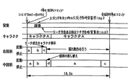
なお、前述したS57において決定されるリーチの種類は、変動表示期間(可変表示期間)の長さをもとに3種類に分けられたものである。後で詳述するが、この実施の形態では、リーチの種類として、19.5秒のリーチ1、24.5秒のリーチ2、29.5秒のリーチ3のうちのいずれかが用いられる。したがって、S57でリーチの種類が決定されると、自動的に変動表示期間が決まることとなる。
【0109】
図13は、S12により示された特別図柄プロセス処理のサブルーチンプログラムを示すフローチャートである。この特別図柄プロセス処理は、特別図柄用プロセスフラグの値に応じて、S300〜S309の10種類の処理のいずれかが実行されるように制御される。S300〜S309において、以下のような処理が実行される。
【0110】
特別図柄変動待ち処理(S300):始動入賞口14(この実施の形態では可変入賞球装置15の入賞口)に打玉が入賞して始動口スイッチ17がオンするのを待つ。始動口スイッチ17がオンすると、始動入賞記憶数が満タンでなければ、始動入賞記憶数を「1」加算更新するとともに大当り判定用乱数を抽出する。すなわち、図11に示された処理が実行される。
【0111】
特別図柄判定処理(S301):特別図柄の可変表示が開始できる状態になると、始動入賞記憶数を確認する。始動入賞記憶数が0でなければ、抽出されている大当り判定用乱数の値に応じて、大当りとするかはずれとするかを決定する。すなわち、図12に示されたS50〜S53等に該当する処理が実行される。
【0112】
停止図柄設定処理(S302):左右中図柄の停止図柄を決定する。すなわち、図12に示されたS54〜S56,S59〜S61等に該当する処理が実行される。
【0113】
リーチ動作設定処理(S303):大当りか否かの判定結果およびリーチ判定用乱数の値等に応じてリーチ表示をするか否かを決定するとともに、リーチ表示をする場合にリーチ種類決定用乱数の値に応じてリーチの種類を決定する。すなわち、図12に示されたS58,S57等に該当する処理が実行される。
【0114】
全図柄変動開始処理(S304):可変表示部9において全図柄が変動開始されるように制御する。このとき、前述したS5の表示制御データ出力処理により、表示制御基板80に対し表示制御コマンドとして、変動時間(リーチの種類等の変動の種類をも含む)を指令する変動時間コマンドと、左右中予定停止図柄(最終停止図柄)をそれぞれ指令する左,中,右の3つの停止図柄コマンドとが送信される。
【0115】
全図柄停止待ち処理(S305):所定時間が経過すると、可変表示部9において表示される全図柄が停止されるように制御する。また、全図柄停止のタイミングまで、所定のタイミングで左右図柄が停止されるように制御する。
【0116】
大当り表示処理(S306):停止図柄が大当り図柄の組合せである場合には、大当り表示用の表示制御コマンドが表示制御基板80に送信されるように制御するとともに内部状態(プロセスフラグ)をステップS307に移行するように更新する。そうでない場合には、内部状態をステップS309に移行するように更新する。なお、大当り図柄の組合せは、左右中図柄が揃った組合せである。また、遊技制御基板80の表示制御用CPU101は表示制御コマンドのデータに従って、可変表示部9に大当り表示を行なう。大当り表示は遊技者に大当りの発生を報知するためになされるものである。
【0117】
大入賞口開放開始処理(S307):大入賞口を開放する制御を開始する。具体的には、カウンタやフラグを初期化するとともに、ソレノイド21を駆動して大入賞口を開放する。
【0118】
大入賞口開放中処理(S308):大入賞口ラウンド表示の表示制御コマンドデータを表示制御基板80に送信する制御や大入賞口の閉成条件の成立を確認する処理等を行なう。大入賞口の閉成条件が成立したら、大当り遊技状態の終了条件が成立していなければ内部状態をS307に移行するように更新する。大当り遊技状態の終了条件が成立していれば、内部状態をS309に移行するように更新する。
【0119】
大当り終了処理(S309):大当り遊技状態が終了したことを遊技者に報知するための表示を行なう。この表示が終了したら、内部フラグ等を初期状態に戻し、内部状態をS300に移行するように更新する。
【0120】
前述したように、始動入賞口14に打玉が入賞すると、基本回路53は、ステップS11(図9参照)の特別図柄プロセス処理において、大当りとするかはずれとするかの決定、停止図柄の決定、変動表示期間の決定等を行ない、その決定に応じた表示制御コマンドおよびINT信号を表示制御基板80に向けて出力する。表示制御基板80側の表示制御用CPU101は、遊技制御基板31からの表示制御コマンドに応じて可変表示部9の表示制御を行なう。
【0121】
図14は、この実施の形態で用いられる左右中図柄の例を示す説明図である。図14に示すように、この実施の形態では、左右中の各特別図柄として変動表示される図柄の種類は、左右中で同一であり、「一」〜「十」、「下駄」、および、「おにぎり」の12図柄である。これらの図柄には、「一」から「おにぎり」まで順に1から12までの図柄番号が定められている。これらの図柄の種類は、変動表示の際に、図柄番号順に表示されていき、図柄番号12の図柄(おにぎり)が表示されると、次に図柄番号1の図柄(一)が表示される。そして、左右中図柄が、たとえば、「一」、「三」、「五」、「七」、「九」、または「下駄」で揃って停止すると、高確率状態となる。すなわち、そのように高確率状態となる図柄が確変図柄である。
【0122】
図15は、この実施の形態で用いられる可変表示部9において特別図柄の背景として表示される背景画面(画像)の例を示す説明図である。この例では、(A)道場(部屋の中ともいう)、(B)閃光、(C)オーラ、および(D)煙の背景が用いられる。また、図15(E)に示された表示は、遊技機の非遊技中等に表示されるデモンストレーション画面の例を示す。ここで、背景とは、可変表示部9での画像表示領域において表示される画像のうち、図柄に対する主にバック画面であり、特別図柄の画像を除く部分の表示部画像を意味する。
【0123】
図16および図17は、この実施の形態で用いられる可変表示部9に表示されるキャラクタの例を示す説明図である。ここで、キャラクタとは、可変表示装置4に表示される人間,動物,あるいは物等を表わす映像をいう。この例では、(A)キャラクタA、(B)キャラクタB、および、(C)キャラクタCの複数種類の異なるキャラクタが用いられる。なお、キャラクタAは、リーチ予告(リーチ予告表示)用のキャラクタとしても用いられる。ここで、リーチ予告とは、リーチが発生する可能性がある旨をリーチ発生前に報知することをいう。この実施の形態では、複数のリーチ予告態様があり、たとえば、キャラクタAの目が光るように表示されると(リーチ予告1)、またはキャラクタAが吹出しで予告すると(リーチ予告2)、リーチ予告が行なわれたことになる。また、キャラクタAは、リーチを成立させるためのキャラクタとしても用いられ、所定の条件が成立すると、キャラクタAの足が右図柄を蹴るように表示されて左右図柄が同一図柄で停止する表示制御が行なわれる。
【0124】
さらに、リーチ動作中にキャラクタA,B,Cは、吹出しによって大当り予告(大当り予告表示)を行なうように表示される。ここで、大当り予告とは、大当りが発生する可能性がある旨を大当り発生前に報知することをいう。この実施の形態では、複数の大当り予告態様(大当り1および2)がある。大当り予告1の態様はそれ自体単独で用いられるが、大当り予告2の態様はそれ自体が単独では用いられず、大当り予告1の表示がなされてから所定時間が経過すると表示される。
【0125】
なお、この実施の形態では、リーチ予告および大当り予告として、それぞれ2つずつの態様が使用されるが、さらに多くの種類を用いてもよい。また、この実施の形態では、キャラクタの吹出しによって予告がなされるが、予告の態様は、遊技者が予告されていることが認識可能であれば、どのような態様によってもよい。たとえば、予告は、通常とは異なるキャラクタの動作や通常とは異なる図柄の変動態様によってしてもよい。さらに、確変図柄で大当りが生じる可能性が高い場合に用いられる予告は、確変大当り予告としてもよい。また、予告を、大当りが発生する確率の高い予告と、大当りが発生する確率が低い予告とに分け、確率が低い方の予告をリーチ予告として定義づけてもよい。
【0126】
ここで、前述した背景とキャラクタとの関係を説明する。前述したように、背景とキャラクタとは別の画像であってもよく、背景にキャラクタが含まれていてもよい。また、背景の場合は、図柄に対する主にバック画面であり、図柄を除く部分の表示部画像を意味するが、キャラクタの場合は、背景に描かれるものに限らず、図柄よりも前(上に重なるという意味)に表示されものであってもよい。
【0127】
なお、ここで用いるキャラクタは、特には人物などで動きのあるものがアニメーション化(動画化)されているのが望ましい。つまり、手足が動く、走る、ジャンプする等の動きが視覚的にアピールするからである。また、同様の理由により、物体であっても、移動する等の動作があるものであれば、そのようなものを用いるのが望ましい。
【0128】
表示制御基板80における表示制御用CPU101は、遊技制御基板31から表示制御コマンドを受信すると、表示制御コマンドにより特定される各変動種類において予め決められている背景やキャラクタを画面上で移動表示する表示制御を行なう。なお、予め決められているタイミングで背景やキャラクタの切替も行なわれるが、それらも、表示制御用CPU101が独自に制御する。
【0129】
図18〜図21は、この実施の形態で用いられる遊技制御基板31から表示制御基板80に送信される表示制御コマンドの例を示す説明図である。この例では、1つの表示制御コマンドは、2バイト(CMD1,CMD2)で構成される。
【0130】
図18は、特別図柄の変動表示における変動表示時間および変動種類を特定可能な変動時間コマンドと、全図柄の停止(確定表示)を指示する全図柄停止コマンドとを示す説明図である。
【0131】
図18を参照して、1バイト目のデータCMD1の値「80H」により、変動時間コマンドまたは全図柄停止コマンドのデータであることが指定される。そして、2バイト目のデータCMD2の値により、変動時間コマンドの場合は変動種類の表示内容が指定され、全図柄変動停止コマンドの場合は全図柄変動停止である旨が指定される。2バイト目のデータが「00H」〜「16H」のデータは変動時間コマンドであり、2バイト目のデータが「17H」のデータは全図柄停止コマンドである。
【0132】
変動時間コマンドの2バイト目のデータにより指定される表示内容としては、特別図柄の変動時間およびその変動種類が指定される。たとえば、指定される変動時間は、7.8S,6.9S,19.5S,24.5S,29.5Sのいずれかが指定される。
【0133】
そして、変動時間7.8Sの場合は、通常のはずれの変動種類が指定される。変動時間6.9Sの場合は、確変時に行なわれる全図柄変動の変動種類が指定される。
【0134】
変動時間19.5Sの場合は、リーチ1の変動種類が指定される。リーチ1の場合は、「−2コマはずれ」,「−1コマはずれ」,「当り」,「+1コマはずれ」,「+2コマはずれ」,「大はずれ」の変動種類が選択的に指定される。変動時間24.5Sの場合は、リーチ2の変動種類が指定される。リーチ2の場合は、「−2コマはずれ」,「−1コマはずれ」,「当り」,「+1コマはずれ」,「+2コマはずれ」,「大はずれ」の変動種類が選択的に指定される。変動時間29.5Sの場合は、リーチ3の変動種類が指定される。リーチ3の場合は、「−1コマはずれ」,「当り」,「+1コマはずれ」の変動種類が選択的に指定される。
【0135】
表示制御基板80の側の制御データROM102においては、各変動時間コマンドが指定する変動時間および変動種類を表示するための表示制御データが記憶されており、変動時間コマンドが指定する変動時間および変動種類にしたがって表示制御が行なわれる。
【0136】
図19は、左図柄に関する停止図柄を指示する表示制御コマンドとしての左停止図柄コマンドを表形式で示す図である。図19に示すように、2バイトのデータCMD1,CMD2で構成される表示制御コマンドによって12種類の左停止図柄(「一」〜「おにぎり」)が指定され得る。なお、それらの指定において、1バイト目のデータCMD1の値は「8B(H)」であって、2バイト目のデータCMD2の値は「00(H)」〜「0B(H)」の範囲内の値をとり得る。
【0137】
図20は、中図柄に関する停止図柄を指定する表示制御コマンドとしての中停止図柄コマンドを表形式で示す図である。図20に示すように、2バイトのデータCMD1,CMD2で構成される表示制御コマンドによって12種類の中停止図柄(「一」〜「おにぎり」)が指定され得る。なお、それらの指定において、1バイト目のデータCMD1の値は「8C(H)」であって、2バイト目のデータCMD2の値は「00(H)」〜「0B(H)」の範囲内の値をとり得る。
【0138】
図21は、右図柄に関する停止図柄を指定する表示制御コマンドとしての右停止図柄コマンドを表形式で示す図である。図21に示すように、2バイトのデータCMD1,CMD2で構成される表示制御コマンドによって12種類の右停止図柄(「一」〜「おにぎり」)が指定され得る。なお、それらの指定において、1バイト目のデータCMD1の値は「8D(H)」であって、2バイト目のデータCMD2の値は「00(H)」〜「0B(H)」の範囲内の値をとり得る。
【0139】
なお、変動時間をコマンドにより指定する場合、CMD2のデータの番号によって指定することに代え、変動時間そのものをコマンドとして指定するようにしてもよい。たとえば、変動時間が10秒の場合には、その時間を指定する「0AH」をCMD2とすることが考えられる。つまり、変動時間のみがわかるコマンドで、その変動時間内での変動内容については表示制御基板80(表示制御用CPU101)が決めるようにしてもよいし、その1つの変動時間に対して1つの変動内容を各々対応させるようにしてもよい。
【0140】
図22は、遊技制御基板31から表示制御基板80に送信される表示制御コマンドを示す説明図である。図22に示すように、この実施の形態では、表示制御コマンドは、表示制御信号CD0〜CD7用の8本の信号線を介して遊技制御基板31から表示制御基板80に送信される。また、遊技制御基板31と表示制御基板80との間には、INT信号用の信号線、表示制御基板80の電源となる+5V、+12Vの供給線、および、接地レベル(GND)を供給するための信号線も配線されている。
【0141】
図23は、遊技制御基板31から表示制御基板80に与えられる表示制御コマンドの送出タイミングの例を示すタイミング図である。この例では、表示制御コマンドのデータを構成する2バイト(CMD1,CMD2)の表示制御データは、図に示すように、基本回路53のタイマ割込み(図においてはタイマ割込みタイミングを規定する定期割込信号として示す)の発生間隔である2ms間に2バイト送出される。そして、表示制御コマンドの1バイト目のデータの出力に同期してINT信号が出力される。表示制御用CPU101にはINT信号の立上がりで割込みがかかるので、表示制御用CPU101が割込み処理プログラムによって各表示制御コマンドのデータを取込むことができる。
【0142】
以下、図24〜図29を参照して、図柄の変動パターンの例について説明する。
【0143】
図24は、各変動パターンを構成する表示パターンを示す説明図である。図25は、リーチとしないはずれ時の図柄の変動パターンの一例を示すタイミングチャートである。また、図26〜図29は、変動種類がリーチである場合(大当りの場合および大当りとしない場合の両方のリーチを含む)の図柄の変動パターンの一例を示すタイミングチャートである。
【0144】
図24を参照して、表示パターンとしては、表に示すようなa〜hの種別が定められており、各変動パターンにおいて組合されて使用される。この図24においては「コマ送り変動」とあるが、これは、特別図柄の表示画像のコマを1コマずつ送っていく(1コマ送っては一旦停止という動作を繰り返す)変動表示である。また、「1コマ逆戻り」とあるが、この場合の逆戻りとは、コマを通常の送り順序と逆の順序で送ることをいう。また、順変動とは、特別図柄が通常のスクロール方向(順方向)に変動することをいい、逆変動とは、特別図柄が通常のスクロール方向とは逆方向に変動することをいう。
【0145】
次に、図25を参照して、リーチとしないはずれ時の図柄の変動パターンを説明する。
【0146】
ここで、変動パターンの説明に先立ち、図25を用いて、表示制御コマンドの送信タイミングを説明する。この実施の形態の場合、表示制御コマンドは、特別図柄の変動開始時に関連したタイミングと、特別図柄の停止図柄の確定時に関連したタイミングとに送信される。変動開始時には、前述した変動パターンコマンド(たとえば図25(A)の場合は8000H)と、左,中,右の停止図柄コマンドとが順次送信される。そのように送信されたコマンドに基づいて、表示制御用CPU101により、以下に説明するような変動パターンで変動表示制御が行なわれるのである。そのような変動表示制御においては、変動開始時の段階で、表示制御用CPU101が、コマンドに基づいてすでに変動時間および予定停止図柄を認識しているので、そのような変動時間経過時に予定停止図柄を確定表示できるように表示制御が行なわれる。そして、表示制御用CPU101は、コマンドにより特定された変動時間経過時に送られてくる全図柄停止コマンドを受信し、その受信に応じて、予定停止図柄を確定表示させる制御を行なう。
【0147】
次に、図25を参照して、リーチとしないはずれ時の図柄の変動パターンを具体的に説明する。図25(A)に示すように、可変表示部9における「左」の図柄表示エリアにおいて、まず、パターンaにしたがって図柄の変動が行なわれる。パターンaは、パターンaは、図24に示すように、少しずつ変動速度が上がるパターンであり、「1」〜「10」、「下駄」、「おにぎり」の順に図柄がスクロールされる。その後、パターンbの一定速の変動が行なわれ、停止図柄の3図柄前の図柄が表示されるように図柄の差替え制御がされた後、パターンcにしたがって3図柄の変動が行なわれる。パターンbでは、パターンaと同様に、「1」〜「10」、「下駄」、「おにぎり」の順に図柄がスクロールされる。パターンcは、図24に示すように、徐々に遅くなって停止するパターンである。
【0148】
また、可変表示部9における「右」の図柄表示エリアにおいて、パターンaにしたがって図柄の変動が行なわれる。その後、一定速変動の後、停止図柄の3図柄前の図柄が表示されるように図柄の差替え制御がされた後、パターンcにしたがって3図柄の変動が行なわれる。「中」の図柄表示エリアにおいても、まず、パターンaの変動が行なわれる。その後、一定速変動の後、停止図柄の3図柄前の図柄が表示されるように図柄の差替え制御がされた後、パターンcにしたがって図柄の変動が行なわれる。
【0149】
なお、表示制御基板80の表示制御用CPU101は、中図柄が確定するまで、左右図柄を変動方向の正方向(順方向)と逆方向とに繰返し変動させる。すなわち、表示制御用CPU101は、左右図柄を、いわゆる揺れ変動状態に表示制御するのである。揺れ変動とは、表示図柄が他の図柄に更新されずに上下に揺れる表示がされることをいう。また、揺れ変動は、最終停止図柄(確定図柄)が表示されるまで行なわれる。そして、表示制御用CPU101は、遊技制御基板31から全図柄停止コマンドを受信すると、左右図柄の揺れ変動状態を終了させて左右中図柄が動かない確定状態に制御する。なお、中図柄も、パターンcによる変動の後に揺れ動作を行ない、その後、確定状態になるようにしてもよい。また、揺れ変動を、図柄を上下に揺らす態様ではなく、左右に揺らしたりする態様としてもよい。
【0150】
図柄が変動している間、表示制御用CPU101は、背景として、「道場」(図15参照)が表示されるように表示制御を行なうとともに、画面中にキャラクタA(図16参照)を表示して適宜キャラクタAを運動させるように表示制御を行なう。具体的には、表示制御用CPU101は、表示する背景およびキャラクタをVDP103に通知する。すると、VDP103は、指示された背景の画像データを作成する。また、VDP103は、指示されたキャラクタの画像データを作成して背景画像と合成し、合成画像を作成する。さらに、VDP103は、合成画像に、左右中図柄の画像データを合成する。VDP103は、キャラクタが運動するような表示制御および図柄が変動するような表示制御も行なう。すなわち、予め決められている運動パターンにしたがってキャラクタの形状および表示位置を変える。また、表示制御用CPU101から通知される変動速度に応じて図柄表示位置を変えていく。
【0151】
なお、表示制御用CPU101は、左右中の図柄表示エリアにおいて、指定された停止図柄で図柄の変動が停止するように、所定のタイミングで停止図柄の3図柄手前の図柄を表示する制御を行なう。変動開始時に表示制御コマンド(変動時間コマンドおよび停止図柄コマンド)により左右中の停止図柄が通知され、かつ、はずれ時の変動時間を含む変動パターンが予め決められているので、表示制御用CPU101は、変動時間コマンドに基づいてパターンaからパターンbへの切替タイミングおよびパターンcへの切替タイミング(図柄の差替えタイミング)を決定するとともに、差替えるべき3図柄前の図柄を予定停止図柄(最終停止図柄)から逆算して決定する。そして、これらの決定に基づいて、表示制御用CPU101は図柄の差替えを含む表示制御を行なう。表示制御用CPU101により決定された差替え図柄は、VDP103に通知され、VDP103は、そのときに表示している図柄に関係なく、差替え通知された図柄を表示する。
【0152】
ここで、前述した図柄の差替えの制御内容をさらに具体的に説明すると、たとえば、次のようになる。左,中,右図柄のうちのある図柄について、前回の変動表示における確定図柄がたとえば「1」である場合、パターンa,パターンbでは「1」、「2」、「3」…というように前述した図柄の表示順序にしたがって図柄が変動していく。そして、パターンcに切替わる時点では、たとえば「3」の図柄を表示する順番であったにもかかわらず、最終停止図柄が「9」の図柄である場合には「3」を表示するのではなく、「6」の図柄に差替え表示するのである。
【0153】
図25(B)は、確率変動状態におけるはずれ時の変動パターンの一例を示すタイミングチャートである。この変動パターンでは、図に示されるように、パターンa、パターンbおよびパターンcにしたがって左右中図柄の変更が行なわれた後に、左右中図柄が同時に停止する。この変動パターンを用いるときも、表示制御用CPU101は、背景として「道場」(図15参照)が表示されるように表示制御を行なうとともに、画面中にキャラクタA(図16参照)を表示して適宜キャラクタAを運動させるように表示制御を行なうことにする。
【0154】
つまり、この実施の形態では、表示制御用CPU101は、遊技制御手段、すなわち、遊技制御基板31のCPU56から「はずれ」であることを指定する表示制御コマンドを受信すると、図25(A)または(B)に示された変動パターンを用いて左右中図柄を可変表示することに決定するとともに、キャラクタAを出現させること、および、「道場」の背景画像を使用することを決定する。
【0155】
図26は、遊技制御基板31から変動時間としてリーチ1の19.5秒が通知されたときに表示される変動パターンの例を示す。表示制御用CPU101は、リーチ1の19.5秒の変動が指定されたコマンドを受けると、19.5秒のリーチ1の変動パターンとして複数用意された変動パターンのうちの何れの変動パターンを用いるのかを独自に決定する。図26には複数の変動パターンとして、(A)〜(C)の3パターンが例示されている。
【0156】
図26(A)に示された変動パターンでは、左右図柄が停止した後、パターンdの中図柄の変動が行なわれる。なお、表示制御用CPU101は、中図柄変動中の左右図柄の停止状態では左右図柄を揺れ動作させている。パターンdは、変動速度が徐々に低下し、その後一定速度で変動が行なわれるパターンである。そして、リーチ動作に入り、パターンbおよびパターンcにしたがって中図柄の変動が行なわれる。表示制御用CPU101は、遊技制御基板31から全図柄停止コマンドを受信すると、左右図柄の揺れ変動状態を終了させ、左右中図柄が動かない確定状態に表示制御する。
【0157】
また、表示制御用CPU101は、遊技制御基板31から通知されている停止図柄で図柄が確定するように、リーチ動作開始前に図柄の差替え(図柄の飛ばし制御)を行なう。変動パターンは、予め決められているので、表示制御用CPU101は、パターンdからパターンbへの切替タイミングおよびパターンbからパターンcへの切替タイミングを認識することができるとともに、差替えるべき3図柄前の図柄も決定できる。なお、中図柄の変動中に、背景およびキャラクタの種類は変化しない。
【0158】
図26(B)に示された変動パターンでは、左右図柄が停止した後パターンdの中図柄の変動が行なわれる。そして、リーチ動作に入り、パターンaおよびパターンcにしたがって中図柄の変動が行なわれる。表示制御用CPU101は、遊技制御基板31から全図柄停止コマンドを受信すると、左右図柄の揺れ変動状態を終了させて左右中図柄が動かない確定状態に表示制御する。また、表示制御用CPU101は、遊技制御基板31から通知されている停止図柄で図柄が確定するように、リーチ動作開始前に図柄の差替え(図柄の飛ばし制御)を行なう。なお、図26(B)に示された変動パターンの場合、右図柄停止時に、表示制御用CPU101は、キャラクタAが右図柄を蹴るように表示制御を行なう(図16参照)。したがって、遊技者は、あたかも、キャラクタAが右図柄を蹴ることによってリーチが成立したように感じる。
【0159】
図26(C)に示された変動パターンでは、左右図柄が停止した後パターンdの中図柄の変動が行なわれる。そして、リーチ動作に入り、パターンb、パターンc、および、パターンhにしたがって中図柄の変動が行なわれる。パターンhは、一時停止の後に、0.9図柄逆変動して0.9図柄順変動するパターンである。表示制御用CPU101は、遊技制御基板31から全図柄停止コマンドを受信すると、左右図柄の揺れ変動状態を終了させ、左右中図柄が動かない確定状態に表示制御する。
【0160】
また、表示制御用CPU101は、遊技制御基板31からコマンドにより通知されている停止図柄で図柄が確定するように、リーチ動作開始前に図柄の差替えを行なう。なお、図26(C)に示された変動パターンの場合、右図柄が停止すると、表示制御用CPU101は、背景画像を「オーラ」(図15参照)に切替えるとともに、画面に現れるキャラクタをキャラクタB(図17参照)に切替える。
【0161】
以上のように、この実施の形態の場合、表示制御用CPU101は、遊技制御基板31のCPU56から変動時間が19.5秒のリーチ1であることを指定する表示制御コマンドを受信すると、図26(A)〜(C)に示された変動パターンのうちのいずれを用いて左右中図柄を可変表示するかを決定する。
【0162】
そして、(A)または(B)の変動パターンを用いることに決定した場合には、左右図柄が停止してリーチ状態になるとキャラクタAおよび「道場」の背景画面を継続して使用することに決定される。(C)の変動パターンを用いることに決定した場合には、リーチ状態になると、キャラクタおよび背景画面をキャラクタBおよび「オーラ」の背景画面に切替えることに決定される。
【0163】
なお、図26(A)〜(C)に示された変動時間19.5秒の変動パターンでも、表示制御用CPU101は、中図柄が確定するまで、左右図柄を上下に揺れ動作させる。また、中図柄の図柄差替え制御は、右図柄が停止するタイミングで実行される。この場合、図柄の差替えタイミングは、表示制御用CPU101により、変動時間コマンドによって特定された変動時間に応じて決められた変動パターンに基づいて決められる(たとえばパターンbからパターンdへの切替タイミング)。さらに、表示制御用CPU101は、変動開始時に遊技制御基板31から停止図柄コマンドにより通知されている中停止図柄(中図柄の確定図柄)と、リーチ変動期間(たとえば図26におけるパターンd、パターンb、およびパターンcの変動時間)における図柄の変動数とに応じて、差替え図柄(たとえば中図柄の差替え図柄)を決定する(たとえば、確定図柄からリーチ変動期間における図柄の変動数だけ逆算して差替え図柄を決定する)。
【0164】
さらに、表示制御用CPU101は、リーチ予告を行なうことに決定している場合には、キャラクタAがリーチ予告1またはリーチ予告2の態様で可変表示部9に表示されるようにVDP103を制御し、大当り予告を行なうことに決定している場合には、リーチ動作中に、そのときに表示されているキャラクタが大当り予告1または大当り予告2の態様で可変表示部9に表示されるようにVDP103を制御する。なお、大当り予告2の態様は、大当り予告1の発展形である。また、表示制御用CPU101は、表示制御コマンドを受信すると、リーチ予告および大当り予告を行なうか否かと、予告を行なう場合は予告の態様とを独自に決定するが、具体的な決め方は後述する。
【0165】
図27は、遊技制御基板31から変動時間としてリーチ2の24.5秒が通知されたときに表示される変動パターンの例を示す。表示制御用CPU101は、リーチ2の24.5秒の変動パターンが指定されたコマンドを受けると、24.5秒のリーチ2の変動パターンとして複数用意された変動パターンのうちの何れの変動パターンを用いるのかを独自に決定する。図27には複数の変動パターンとして、(A)〜(C)の3パターンが例示されている。
【0166】
図27(A)に示された変動パターンでは、左右図柄が停止した後、パターンdの中図柄の変動が行なわれる。なお、表示制御用CPU101は、中図柄変動中の左右図柄の停止状態では左右図柄を揺れ動作させている。そして、リーチ動作に入り、パターンb、パターンcおよびパターンfにしたがって中図柄の変動が行なわれる。パターンfは高速変動であり、パターンfによる変動開始前に一時停止期間がおかれる。表示制御用CPU101は、遊技制御基板31から全図柄停止コマンドを受信すると、左右図柄の揺れ変動状態を終了させ、左右中図柄が動かない確定状態に表示制御する。
【0167】
また、表示制御用CPU101は、遊技制御基板31からコマンドにより通知されている停止図柄で図柄が確定するように、リーチ動作開始前に図柄の差替えを行なう。つまり、中図柄の図柄差替え制御は、右図柄が停止するタイミングで実行される。この場合、図柄の差替えタイミングは、表示制御用CPU101により、変動時間コマンドによって特定された変動時間に応じて決められた変動パターンに基づいて決められる(たとえばパターンbからパターンdへの切替タイミング)。さらに、表示制御用CPU101は、変動開始時に遊技制御基板31から停止図柄コマンドにより通知されている中停止図柄(中図柄の確定図柄)と、リーチ変動期間(たとえば図27におけるパターンd、パターンb、およびパターンcの変動時間)における図柄の変動数とに応じて、差替え図柄(たとえば中図柄の差替え図柄)を決定する(たとえば、確定図柄からリーチ変動期間における図柄の変動数だけ逆算して差替え図柄を決定する)。
【0168】
図27(A)に示された変動パターンを実行する場合には、表示制御用CPU101は、パターンfが高速変動するパターンであることを予め認識する。そして、表示制御用CPU101は、パターンfの変動速度と変動期間とを考慮して、左,中,右停止図柄コマンドにより通知されている最終停止図柄から一時停止図柄を逆算して求め、求めた図柄を再変動時の一時停止図柄として、再変動の制御に用いる。そして、この場合、表示制御用CPU101は、一時停止図柄が遊技制御基板31からコマンドにより通知されている最終停止図柄と一致するように、リーチ動作開始前に中図柄の差替えを行なう。
【0169】
なお、図27(A)に示された変動パターンでは、右図柄が停止すると、表示制御用CPU101は、背景画像を「閃光」(図15参照)に切替える。また、右図柄停止時に、表示制御用CPU101は、キャラクタAが右図柄を蹴るように表示する制御を行なう(図16参照)。
【0170】
図27(B)に示された変動パターンでは、左右図柄が停止した後、パターンdの中図柄の変動が行なわれる。そして、リーチ動作に入り、パターンb、パターンc、および、パターンhにしたがって中図柄の変動が行なわれる。表示制御用CPU101は、遊技制御基板31から全図柄停止コマンドを受信すると、左右図柄の揺れ変動状態を終了させ、左右中図柄が動かない確定状態に表示制御する。また、表示制御用CPU101は、遊技制御基板31から通知されている停止図柄で図柄が確定するように、リーチ動作開始前に図柄の差替えを行なう。なお、図27(B)に示された変動パターンの場合、右図柄が停止すると、表示制御用CPU101は、背景画像を「閃光」(図15参照)に切替える。
【0171】
図27(C)に示された変動パターンでは、左右図柄が停止した後パターンdの中図柄の変動が行なわれる。そして、リーチ動作に入り、パターンbおよびパターンcにしたがって中図柄の変動が行なわれる。表示制御用CPU101は、遊技制御基板31から全図柄停止コマンドを受信すると、左右図柄の揺れ変動状態を終了させて左右中図柄が動かない確定状態に表示制御する。また、表示制御用CPU101は、遊技制御基板31からコマンドにより通知されている停止図柄で図柄が確定するように、リーチ動作開始前に図柄の差替え(図柄の飛ばし制御)を行なう。図27(C)に示された変動パターンの場合、右図柄が停止すると、表示制御用CPU101は、背景画像を「オーラ」(図15参照)に切替えるとともに、画面に現れるキャラクタをキャラクタB(図17参照)に切替える。
【0172】
以上のように、この実施の形態の場合、表示制御用CPU101は、遊技制御基板31のCPU56から変動時間が24.5秒のリーチ2であることを指定する表示制御コマンドを受信すると、図27(A)〜(C)に示された変動パターンのうちのいずれを用いて左右中図柄を可変表示するかを決定する。
【0173】
そして、(A)または(B)の変動パターンを用いることに決定した場合には、左右図柄が停止してリーチ状態になると背景画面を「閃光」に切替えることに決定される。また、(C)の変動パターンを用いることに決定した場合には、リーチ状態になると背景画面を「オーラ」に切替えることに決定される。
【0174】
なお、図27(A)〜(C)に示された変動時間24.5秒の変動パターンでも、表示制御用CPU101は、中図柄が確定するまで、左右図柄を上下に揺れ動作させる。また、中図柄の図柄飛ばし制御は、右図柄が停止するタイミングで実行される。
【0175】
さらに、表示制御用CPU101は、リーチ予告を行なうことに決定している場合には、キャラクタAがリーチ予告1またはリーチ予告2の態様で可変表示部9に表示されるようにVDP103を制御し、大当り予告を行なうことに決定している場合には、リーチ動作中に、そのときに表示されているキャラクタが大当り予告1または大当り予告2の態様で可変表示部9に表示されるようにVDP103を制御する。
【0176】
図28および図29は、遊技制御基板31から変動時間としてリーチ3の29.5秒が通知されたときに表示される変動パターンの例を示す。表示制御用CPU101は、リーチ3の29.5秒の変動パターンが通知されると、29.5秒のリーチ3の変動パターンとして複数用意された変動パターンのうちの何れの変動パターンを用いるのかを独自に決定する。図28および図29には複数の変動パターンとして、(A)〜(C)の3パターンが例示されている。なお、(C1)および(C2)の変動パターンは、1つの変動パターンの異なる局面を示す例である。よって、以下、図29(C1)および(C2)に例示された変動パターンを図29(C)に示された変動パターンと呼ぶことがある。
【0177】
図28(A)に示された変動パターンでは、左右図柄が停止した後、パターンdの中図柄の変動が行なわれる。なお、表示制御用CPU101は、中図柄変動中に左右図柄を揺れ動作させている。そして、リーチ動作に入り、パターンbおよびパターンcによる変動後、一時停止期間をおいてパターンfにしたがって中図柄の変動が行なわれる。また、表示制御用CPU101は、遊技制御基板31から左,中,右停止図柄コマンドにより通知されている停止図柄で図柄が確定するように、リーチ動作開始前に図柄の差替えを行なう。なお、図28(A)に示された変動パターンでは、右図柄が停止すると、表示制御用CPU101は、背景画像を「閃光」(図15参照)に切替える。
【0178】
さらに、図28(A)に示された変動パターンでは、中図柄がパターンfで高速変動する際に、左右図柄も同様に高速変動する。したがって、左,中,右停止図柄コマンドにより通知されている最終停止図柄が大当り図柄の組合せである場合には、一時停止時の一時停止図柄も、図柄の種類は異なるが、やはり大当り図柄の組合せである。よって、一時停止時に大当り図柄となり、その後、左,中,右図柄がパターンfで高速変動により再変動した場合に、遊技者は、一時停止時に大当り図柄が発生したと感じるとともに、再変動後に再度大当り図柄が提供されて再度興趣がかき立てられる。このように一時停止期間をおいて図柄が再度変動開始された後停止図柄を確定表示する制御を再変動制御(再更新制御ともいう)という。なお、一時停止図柄は、表示制御用CPU101が停止図柄から逆算して独自に決定する図柄である。パターンfの変動速度と変動期間とは予め決められているので、表示制御用CPU101は、パターンfの変動速度と変動期間とを考慮して、左,中,右停止図柄コマンドにより通知されている最終停止図柄から一時停止図柄を逆算して求め、求めた図柄を再変動時の一時停止図柄として、前述したような再変動の制御に用いる。
【0179】
図28(B)に示された変動パターンでは、左右図柄が停止した後パターンdの中図柄の変動が行なわれる。なお、表示制御用CPU101は、中図柄変動中に、左右図柄を揺れ動作させている。そして、リーチ動作に入り、パターンbおよびパターンhによる変動後、一時停止期間をおいてパターンfにしたがって中図柄の変動が行なわれる。また、表示制御用CPU101は、遊技制御基板31からコマンドにより通知されている停止図柄で図柄が確定するように、リーチ動作開始前に図柄の差替えを行なう。なお、図28(B)に示された変動パターンでは、右図柄が停止すると、表示制御用CPU101は、背景画像を「オーラ」(図15参照)に切替えるとともに、画面に現れるキャラクタをキャラクタB(図17参照)に切替える。さらに、図28(B)に示された変動パターンでは、中図柄がパターンfで高速変動する際に、左右図柄も同様に高速変動する。
【0180】
さらに、図29(C)に示された変動パターンでは、左右図柄が停止した後、パターンdにしたがって中図柄の変動が行なわれる。その後、パターンgにしたがって中図柄の変動が行なわれる。パターンgは、コマ送りのパターンである。また、表示制御用CPU101は、遊技制御基板31からコマンドにより通知されている停止図柄で図柄が確定するように、リーチ動作開始前に図柄の差替えを行なう。なお、図29(C)に示された変動パターンでは、右図柄が停止すると、表示制御用CPU101は、背景画像を「煙」(図15参照)に切替えるとともに、画面に現れるキャラクタをキャラクタC(図17参照)に切替える。
【0181】
図28および図29に示された変動時間29.5秒の変動パターンでも、表示制御用CPU101は、中図柄が確定するまで、左右図柄を上下に揺れ動作させる。また、中図柄の図柄飛ばし制御は、右図柄が停止するタイミングで実行される。
【0182】
図29(C)に示されたコマ送りを含む変動パターンでは、リーチ動作開始時に、大当りとするか否かにかかわらず、左右中の表示図柄を揃ったものとする。すると、左右中図柄の停止図柄は、変動開始時に遊技制御基板31から表示制御基板80に送信されているので、停止図柄とリーチ動作開始時の図柄(左右中図柄が揃ったもの)とからコマ送り時のコマ数が決まる。
【0183】
たとえば、図29(C1)に示された例は、確定図柄が「七」(左図柄)、「八」(中図柄)、「七」(右図柄)の+1コマはずれであった場合の例である。リーチ動作開始時の図柄は「七」、「七」、「七」であるから、コマ送り時には13図柄の変動がなされる必要がある。また、図29(C2)に示された例は、確定図柄が「七」(左図柄)、「六」(中図柄)、「七」(右図柄)の−コマはずれであった場合の例である。リーチ動作開始時の図柄は「七」、「七」、「七」であるから、コマ送り時には11図柄の変動がなされる必要がある。なお、図示をしていないが、確定図柄が「七」(左図柄)、「七」(中図柄)、「七」(右図柄)の大当りであった場合には、リーチ動作開始時の図柄である「七」、「七」、「七」から、コマ送り時には12図柄の変動がなされる必要がある。
【0184】
この場合、コマ送りの期間を常に一定にしておくと、変動時間が29.5秒からずれてしまう。変動時間をずらさないようにするには、送りコマ数に応じてコマ送りの変動速度を変えることが考えられる。しかし、そのような表示制御を行なうのは不自然である。つまり、遊技者に不信感を与える。そこで、この実施の形態の場合、表示制御用CPU101は、図29(C)に示された変動パターンを用いることに決定した場合には、コマ送り変動時の変動速度が常に一定になるようにリーチ動作開始時のタイミングを調整する。
【0185】
つまり、送りコマ数が少ないときにはたとえばパターンbの期間を相対的に長くすることによりリーチ動作開始のタイミングを相対的に遅らせ、送りコマ数が多いときにはたとえばパターンbの期間を相対的に短くすることによりリーチ動作開始のタイミングを相対的に早める。そのような表示制御を行なえば、全体の変動時間が29.5秒に保たれた上で、コマ送り変動時の変動速度を常に一定にすることができる。なお、この例では、パターンbの期間の長さを調整することにより、リーチ動作開始のタイミングの調整を行なう例を示したが、その他のパターンの期間の長さを調整することによりリーチ動作開始のタイミングの調整を行なうようにしてもよい。
【0186】
以上のように、この実施の形態の場合、表示制御用CPU101は、遊技制御基板31のCPU56から変動時間が29.5秒のリーチ3であることを指定する表示制御コマンドを受信すると、図28(A),(B)および図29(C)に示された変動パターンのうちのいずれを用いて左右中図柄を可変表示するかを決定する。
【0187】
そして、(A)の変動パターンを用いることに決定した場合には、左右図柄が停止してリーチ状態になると背景画面を「閃光」に切替えることに決定される。また、(B)の変動パターンを用いることに決定した場合には、左右図柄が停止してリーチ状態になると背景画面を「オーラ」に切替えることに決定される。また、(C)の変動パターンを用いることに決定した場合には、リーチ状態になると背景画面を「煙」に切替えることに決定される。
【0188】
以下、上述した表示例を実現するための遊技制御および表示制御について説明する。
【0189】
図30は、図11に示された特別図柄プロセス処理における全図柄変動開始処理(S304)を示すフローチャートである。S302の停止図柄設定処理およびS303のリーチ動作設定処理において変動時間と停止図柄とが決定されると、それらを指示するための表示制御コマンドの送出制御が行なわれるが、全図柄変動開始待ち処理では、まず、コマンドの送出完了を待つ(S304a)。なお、コマンド送出完了の情報は、図7に示された表示制御データ出力処理(S6)から通知される。
【0190】
この実施の形態の場合、CPU56は、図柄の変動を開始させるときに、図18に示された変動時間コマンドのうちのいずれかを表示制御基板80に送出する。また、続けて、すでに決定されている左右中図柄を示す左,右,中停止図柄コマンド(図19〜図21参照)を表示制御基板80に送出する。よって、S304aのコマンド送信完了を待つステップでは、それらすべてのコマンドの送出が完了したか否かが確認される。なお、CPU56は、左,右,中停止図柄コマンドを送出してから変動時間コマンドを送出してもよい。
【0191】
なお、表示制御コマンドとしては、大当り予告およびリーチ予告等の予告を行なうか否かを特定可能なコマンドを送出し、そのコマンドの内容に基づいて、表示制御基板80側で、そのような予告をするか否かを決定するようにしてもよい。そのような予告をするか否かを特定可能な情報は、変動時間コマンドに含めてもよく(予告ありの変動時間を特定可能なコマンドと予告なしの変動時間を特定可能なコマンドとを定義してもよい)、変動時間コマンドとは別のコマンドとしてもよい。
【0192】
表示制御コマンドの送出が完了すると、CPU56は、コマンドにより表示制御基板80に通知した変動時間を測定するための変動時間タイマをスタートする(S304b)。そして、S305の全図柄停止待ち処理に移行するように、特別図柄プロセスフラグを更新する(S304c)。
【0193】
図31は、図13に示された特別図柄プロセス処理における全図柄停止待ち処理(S305)を示すフローチャートである。この処理では、変動時間タイマにより、変動時間がタイムアップしたか否かをCPU56が確認する(S305a)。タイムアップしたら、全図柄停止を指示する全図柄停止コマンドを設定する(S305b)。そして、表示制御コマンドデータ送出要求フラグをセットし(S305c)、S306の大当り表示処理に移行するように、特別図柄プロセスフラグを更新する(S305d)。なお、表示制御コマンドデータ送出要求フラグは、図9で前述した表示制御データ設定処理(S5)で参照される。
【0194】
以上のように、特別図柄プロセス処理において、CPU56は、変動の開始時に変動時間を特定可能な情報と、停止図柄を特定可能な情報とを表示制御基板80に送出し、変動時間タイマがタイムアップしたら、すなわち、指示した変動時間が終了したら、全図柄停止を指示する情報を表示制御基板80に送出する。その間、CPU56は、表示制御基板80に表示制御コマンドを送出しない。したがって、遊技制御基板31のCPU56における表示制御に要する負荷は、大きく低減されている。
【0195】
図32は、表示制御データ設定処理(図9に示されたS5)を示すフローチャートである。表示制御データ設定処理において、CPU56は、まず、データ送出中フラグがセットされているか否かを確認する(S411)。ここで、データ送出中フラグは、後述する表示制御データ出力処理において、表示制御コマンドが送出中であることを示すためにセットされるフラグである。データ送出中フラグがセットされていなければ、表示制御コマンドデータ送出要求フラグがセット(ON)されているか否かを確認する(S412)。ここで、表示制御コマンドデータ送出要求フラグは、表示制御コマンドを送出することが要求されていることを示すために特別図柄プロセスフラグでセットされるフラグである。表示制御コマンドデータ送出要求フラグがセットされていれば、そのフラグをリセットする(S413)。また、送出すべき表示制御コマンドのデータを出力データ格納領域に設定するとともに(S414)、ポート出力要求フラグをセットし(S416)、この処理が終了する。
【0196】
次に、図33を用いて前述したS6の表示制御データ出力処理を説明する。図33は、表示制御データ出力処理を示すフローチャートである。
【0197】
まず、S211により、前述したポート出力要求フラグがセットされているか否かが判断される。S211によりポート出力要求フラグがセットされていないと判断された場合には、この表示制御データ出力処理が終了する。これにより、出力すべき表示制御コマンドのデータがない場合には、コマンドデータの出力に関する処理が行なわれない。一方、S211によりポート出力要求フラグがセットされていると判断された場合には、S212に進み、ポート出力要求フラグをリセットする処理がなされる。
【0198】
次に、S213に進み、出力データ格納領域に格納されているデータの1バイト目を、表示制御コマンドデータ出力用の出力バッファ回路63から出力させる処理がなされる。この1バイト目のデータは、所定期間にわたって出力される。これにより、出力データ格納領域に格納されている表示制御コマンドデータのうちの1バイト目が表示制御基板80に向けて伝送される。次に、S214に進み、ポート出力カウンタを「1」だけ加算更新する処理がなされる。ここで、ポート出力カウンタは、1つの表示制御コマンドデータについての出力されたデータのバイト数を計数するためのカウンタであり、「0」を初期値として計数を行なう。次に、S215に進み、INT信号の予め定められたONタイミング(アクティブ状態となるタイミング)の経過を待って信号INT信号をON状態(アクティブ状態、すなわち、ローレベル)にする処理がなされる。これにより、1バイト目のデータの取込用のINT信号がアクティブ状態(ローレベル)となる。次に、S216に進み、データ送信中フラグをON(セット)状態にする処理がなされる。これにより、表示制御コマンドデータの送信中である旨が示される。
【0199】
次に、S217に進み、前述したポート出力カウンタの値が「2」であるか否かの判断がなされる。つまり、表示制御コマンドデータの1バイト目を出力中の時点ではポート出力カウンタの値は「1」になるため、ここでは、1バイト目の出力中であるか否かが判断されるのである。S217によりポート出力カウンタの値が「2」であると判断された場合は、後述するS218に進む。一方、S217によりポート出力カウンタの値が「2」ではないと判断された場合は、1バイト目の出力中であり、S221に進み、表示制御信号INTの予め定められたOFFタイミングの経過を待って表示制御信号INTをOFF状態にする処理がなされる。
【0200】
次に、S222に進み、出力データ格納領域に格納されているデータの2バイト目を、表示制御コマンドデータ出力用の出力バッファ回路63から出力させる処理がなされる。これにより、出力データ格納領域に格納されている表示制御コマンドデータのうちの残りの2バイト目が表示制御基板80に向けて伝送される。この2バイト目のデータは、所定期間にわたって出力される。次に、S223に進み、ポート出力カウンタを「1」だけ加算更新する処理がなされる。これにより、2バイト目のデータが出力された場合に、ポート出力カウンタは「2」となる。
【0201】
次に、S224に進み、INT信号の予め定められたONタイミングの経過を待ってINT信号をON状態にする処理がなされる。これにより、2バイト目のデータの取込用のINT信号がアクティブ状態(ローレベル)となる。その後、S217に戻る。S224からS217に進んだ場合は、ポート出力カウンタが「2」となっているので、S217からS218に進む。
【0202】
S218においては、ポート出力カウンタをクリアする処理がなされる。次に、S219に進み、INT信号の予め定められたOFFタイミングの経過を待ってINT信号をOFF状態にする処理がなされる。その後、S220に進み、2バイト目の表示制御コマンドデータの出力が停止状態になるのを待って、データ送信中フラグをOFF状態にする処理がなされる。これにより、1つの表示制御コマンドデータの出力処理が終了し、次の表示制御コマンドデータを出力することが可能になる。
【0203】
このような表示コマンド出力処理においては、図示されていないが、各ステップが実行されるタイミングが予め定められたタイムスケジュールにしたがって時間管理されている。これにより、表示制御コマンドデータについては、図23に示されるように、2msの間に2バイトのデータが出力される。
【0204】
以上のように、表示制御データ出力処理においては、ポート出力要求に応じて、出力コマンドデータ格納領域に格納されているデータを1バイトずつ順次出力することにより、表示制御コマンドのデータを出力する。
【0205】
次に、表示制御用CPU101の動作を説明する。
図34は、表示制御用CPU101のメイン処理を示すフローチャートである。メイン処理では、表示制御用CPU101は、まず、RAM、I/OポートおよびVDP103等を初期化する(S701)。そして、可変表示部9にデモンストレーション画面が出現するように表示制御する(S702)。その後、表示用乱数更新処理(表示用乱数を生成するランダムカウンタの更新処理)を繰返し実行する(S703)。
【0206】
図35は、表示制御用CPU101が扱う表示用乱数を示す説明図である。図33に示すように、この実施の形態では、S703で更新される表示用乱数として、リーチ表示態様決定用乱数(RS1)、リーチ予告用乱数(RS2)、および、大当り予告用乱数(RS3)を含む。リーチ表示態様決定用乱数は、表示制御コマンドにより特定された各リーチについて、図26〜図29に示されるような変動パターンを決定するためのものであり、0〜29の数値範囲で繰返し更新され、予め定められた抽出条件が成立した場合に抽出される。リーチ予告用乱数は、リーチ予告を行なうか否かを決定するためのものであり、0〜7の数値範囲で繰返し更新され、予め定められた抽出条件が成立した場合に抽出される。大当り予告用乱数は、大当り予告を行なうか否かを決定するためのものであり、0〜2の数値範囲で繰返し更新され、予め定められた抽出条件が成立した場合に抽出される。
【0207】
図36は、抽出されたリーチ表示態様決定用乱数とリーチ表示態様(変動パターン)との関係(図36(A))、抽出されたリーチ予告用乱数とリーチ予告との関係(図36(B))、抽出された大当り予告用乱数と大当り予告との関係(図36(C))を示す説明図である。
【0208】
図36(A)において、A,B,Cは、図26〜図29における(A),(B),(C)に対応している。すなわち、抽出されたリーチ表示態様決定用乱数の値が上段に示される値であれば、表示制御用CPU101は、下段に示された変動パターン(リーチ表示態様)で図柄の変動を行なうことに決定する。たとえば、遊技制御基板31から受けた表示制御コマンドにより29.5秒のリーチ3での変動により大当りとする場合が通知され、抽出したリーチ表示態様決定用乱数の値が21である場合には、図29(C)に示された変動パターンで変動を行なうことに決定する。この場合の大当りとするか否かの判断は、変動時間コマンドと左,中,右停止図柄コマンドとのどちらのコマンドに基づいて判定してもよい。
【0209】
また、図36(B)を参照して、表示制御用CPU101は、受信した表示制御コマンドに基づいて、リーチ予告用乱数を抽出し、その抽出値に基づいて、リーチ予告1をするか、リーチ予告2をするか、リーチ予告をしないかのいずれかを抽選により決定する。表示制御コマンドによりリーチにすることが指示されている場合には、抽選において、抽出値が0〜3のいずれかであればリーチ予告を行なわないことに決定し、抽出値が4または5であればリーチ予告1の態様でリーチ予告を行なうことに決定し、抽出値が6または7であればリーチ予告2の態様でリーチ予告を行なうことに決定する。このような決定は、図に示されるようなリーチ時における抽出値とリーチ予告態様との関係を示したリーチ時用テーブルと呼ばれるデータを用いて行なわれる。一方、表示制御コマンドによりリーチにしないことが指示されている場合(リーチ時以外の場合)には、抽選において、抽出値が0〜6のいずれかであればリーチ予告を行なわないことに決定し、抽出値が7であればリーチ予告1の態様でリーチ予告を行なうことに決定する。このような決定は、図に示されるようなリーチ時以外における抽出値とリーチ予告態様との関係を示したリーチ時以外用テーブルと呼ばれるデータを用いて行なわれる。
【0210】
また、図36(C)を参照して、表示制御用CPU101は、受信した表示制御コマンドに基づいて大当り予告用乱数を抽出し、その抽出値に基づいて、大当り予告1をするか、大当り予告2をするか、大当り予告をしないかのいずれかを抽選により決定する。抽選において、表示制御コマンドにより大当りにすることが指示されている場合には、抽出値が0であれば大当り予告表示を行なわないことに決定し、抽出値が2であれば大当り予告1の態様で大当り予告表示を行なうことに決定し、抽出値が3であれば大当り予告2の態様で大当り予告表示を行なうことに決定する。このような決定は、図に示されるような大当り時における抽出値と大当り予告態様との関係を示した大当り時用テーブルと呼ばれるデータを用いて行なわれる。一方、抽選において、表示制御コマンドにより大当りにしないことが指示されている場合(はずれ時の場合)には、抽出値が0,1のいずれかであれば大当り予告表示を行なわないことに決定し、抽出値が2であれば大当り予告1の態様で大当り予告表示を行なうことに決定する。このような決定は、図に示されるようなはずれ時における抽出値と大当り予告態様との関係を示したはずれ時用テーブルと呼ばれるデータを用いて行なわれる。
【0211】
ここで、予告表示とは、大当り予告表示(大当り予告態様)やリーチ予告表示(リーチ予告表示態様)などだが、予告表示は、小当りの予告や中当りの予告などでもよいし、さらに確変大当り予告やスーパーリーチ予告といった予告をする表示であってもよい。さらに、予告表示は、前述したリーチ予告2のようにリーチ予告すれば必ずリーチとなるものでもよいし、前述したリーチ1のようにリーチとならないときにガセ(偽り)の予告を行なうものも含む。リーチ予告とは、リーチとするかしないかに基づいて行なうものであり、大当り予告とは、大当りとするかしないかに基づいて行なうものである。
【0212】
具体的に、リーチ予告をするか否かは、基本的に、リーチとするかしないかに基づいて行なうものである。つまり、リーチ予告をするか否かは、表示制御コマンドによりリーチ表示態様(はずれとなるリーチおよび大当りとなるリーチの両方を含む)となることが特定されているか否かに応じて決定される。なお、リーチ表示態様となることがコマンドにより特定されている場合(リーチとする場合)であっても、一定の割合でリーチ予告を行なわないようにしてもよく、リーチ表示態様とならないことがコマンドにより特定されている場合(リーチとしない場合)であっても、一定の割合でリーチ予告を行なうようにしてもよい。
【0213】
また、大当り予告をするか否かは、基本的に、大当りとするかしないかに基づいて行なうものである。具体的には、表示制御コマンドにより大当り表示態様となることが特定されているか否かに応じて決定される。なお、大当り表示態様となることがコマンドにより特定されている場合(大当りとする場合)であっても、一定の割合で大当り予告を行なわないようにしてもよく、大当り表示態様とならないことがコマンドにより特定されている場合(大当りとしない場合)であっても、一定の割合で大当り予告を行なうようにしてもよい。これらの予告成立条件は、変動時間コマンドおよび左,中,右停止図柄コマンドの両方を参照して判断するようにしてもよい。
【0214】
なお、この例では、リーチとするかしないかに基づいてリーチ予告をするか否かを決定し、大当りとするかしないかに基づいて大当り予告をするか否かを決定する場合を示しているが、予告対象としては、リーチおよび大当りの両方を含むような予告を行なうようにしてもよい。大当りの場合とはずれの場合とで場合分けをし、さらに、はずれの場合にリーチとするかリーチとしないかで場合分けをしてリーチ予告および大当り予告の両方を含む所定の予告を複数種類行なうようにしてもよい。つまり、所定の予告をするか否かは、リーチとするかしないかおよび大当りとするかしないかの両方の判断に基づいてを決定するようにしてもよい。
【0215】
この実施の形態では、実際の変動制御等は、タイマ割込処理によって行なわれる。タイマ割込は、たとえば2ms毎に発生する。図37は、タイマ割込処理を示すフローチャートである。図37に示すように、タイマ割込処理では、表示制御用CPU101が、表示制御プロセス処理を実行する(S701)。表示制御プロセス処理では、表示制御プロセスフラグの値に応じた表示制御が行なわれる。
【0216】
遊技制御基板31からの表示制御コマンドは、IRQ2割込によって表示制御用CPU101に受信される。図38は、表示制御用CPU101のIRQ2割込処理を示すフローチャートである。IRQ2割込処理において、表示制御用CPU101は、まず、データ受信中フラグがセットされているか否かを確認する(S601)。セットされていなければ、この割込が表示制御コマンドデータにおける第1バイトの表示制御データ送出による割込である。そこで、ポインタをクリアするとともに(S602)、データ受信中フラグをセットする(S603)。そして、S604に移行する。ここで、ポインタは、表示制御用CPU101が内蔵しているRAMにおける表示制御コマンドデータ格納エリアにおける何バイト目に受信データを格納するかを指示するものである。
【0217】
データ受信中フラグがセットされている場合、INT信号がオフしたら(S604)、表示制御用CPU101は、入力ポートからデータを入力し、表示制御コマンドデータ格納エリアにおいてポインタにより示されているアドレスに、入力データを格納する(S605)。
【0218】
そして、表示制御用CPU101は、ポインタの値を+1する(S606)。そして、ポインタの値が2になった場合には(S607)、2バイトで構成される表示制御コマンドデータの受信が完了したことになるので、データ受信完了フラグをセットするとともに、データ受信中フラグをリセットする(S608,S609)。以上のような処理によって、2バイトの表示制御データCMD1,CMD2が、表示制御基板80において受信される。
【0219】
図39は、図37に示されたタイマ割込処理における表示制御プロセス処理(ステップS711)を示すフローチャートである。表示制御プロセス処理では、表示制御プロセスフラグの値に応じてS720、S750、S780、S810、S840、S870のうちのいずれかの処理が行なわれる。各処理においては、以下のような処理が実行される。
【0220】
表示制御コマンド受信待ち処理(S720)では、IRQ2割込処理によって変動時間コマンドを受信したか否かを確認する。リーチ動作設定処理(S750)では、リーチ状態を表示する場合に、図26〜図29に示された変動パターンのうちのいずれのパターンを使用するのか決定する。リーチ動作設定処理では、さらに、リーチ予告および大当り予告をそれぞれ行なうか否かを決定するとともに、予告を行なうことに決定した場合には予告の種類を決定する。全図柄変動開始処理(S780)では、左中右図柄の変動が開始されるように制御する。図柄変動中処理(S810)では、変動パターンを構成する各変動状態(変動速度、キャラクタ、背景)の切替タイミングを制御するとともに、変動時間の終了を監視する。また、左右図柄の停止制御を行なう。全図柄停止待ち処理(S840)では、変動時間の終了時に、全図柄停止コマンドを受信していたら、図柄の変動を停止し、最終停止図柄(確定図柄)を表示する制御を行なう。大当り表示処理(S870)では、変動表示制御時間の終了後、確変大当り表示または通常大当り表示の制御を行なう。
【0221】
図40は、表示制御コマンド受信待ち処理(S720)を示すフローチャートである。表示制御コマンド受信待ち処理において、表示制御用CPU101は、まず、コマンド無受信タイマがタイムアウトしたか否かを確認する(S721)。ここで、コマンド無受信タイマは、所定期間以上、遊技制御基板31から図柄の変動を示す表示制御コマンドを受信しなかったときにタイムアウトとする。コマンド無受信タイマがタイムアウトした場合に、表示制御用CPU101は、可変表示部9にデモンストレーション画面を表示する制御を行なう(S722)。
【0222】
コマンド無受信タイマがタイムアウトしていなければ、表示制御用CPU101は、変動時間を特定可能な表示制御コマンド(具体的には変動時間コマンド)を受信したか否かを確認する(S723)。変動時間コマンドを受信したバッファには、表示制御プロセスフラグの値をリーチ動作設定処理(S750)に対応した値に変更する(S724)。
【0223】
この段階で、遊技制御基板31から表示制御基板80に送信される表示制御コマンドは、変動時間コマンドと、左,中,右の停止図柄コマンドとである。それらは、前述した表示制御データ格納エリアに格納されている(図38におけるS605参照)。なお、以下、停止図柄コマンドにより特定される停止図柄を仮停止図柄と呼ぶ。
【0224】
図41は、リーチ動作設定処理(S750)を示すフローチャートである。リーチ動作設定処理において、表示制御用CPU101は、まず、リーチ予告決定処理(図42参照)により、リーチ予告を行なうか否かを決定する(S751)。次いで、受信した変動時間コマンドに基づいて、当該コマンドにより指示された変動表示がリーチにもならないはずれであるか否かを判断する(S752)。具体的には、図18に示された通常はずれまたは確変時全図柄変動のコマンドを受信した場合が、S752によるはずれに該当する。
【0225】
はずれであるならば、左右の仮停止図柄が異なっているものであるか否か確認する(S753)。一致していた場合には、右停止図柄を1図柄ずらしたものとする(S754)。そして、左中右の仮停止図柄を所定の記憶エリアに格納(記憶)する(S755)。また、監視タイマにタイムアウト時間として7.9秒を設定する(S756)。ここで、監視タイマは、変動時間を監視するためのタイマである。ここで設定される7.9秒は、はずれ時の変動時間である7.8秒に対して余裕を持たせた値である。監視タイマがタイムアウトする前に全図柄停止コマンドを受信できなかったときには、所定の処理が行なわれる。
【0226】
S752において、はずれでなかったら、すなわち、図18に示される8002H〜8016のうちのいずれかを受信していたら、左右の仮停止図柄が同一か否かを確認する(S757)。仮停止図柄が異なっていた場合には、右仮停止図柄を左仮停止図柄と同じものにする(S758)。そして、左中右の仮停止図柄を所定のエリアに格納する(S759)。また、表示制御用CPU101は、変動時間コマンドが特定する変動時間に0.1秒を加算した値を監視タイマに設定する(S760)。そして、リーチ表示態様決定処理(図43参照)により、リーチ時の変動パターン(表示態様)を決定する(S761)。そして、大当り予告決定処理(図44参照)により、大当り予告を行なうか否かを決定する(S762)。
【0227】
以上のように、この実施の形態では、表示制御用CPU101は、可変表示(変動表示)を開始させる際に、受信した変動時間コマンドにより特定されたリーチ等の変動種類と、受信した左,中,右停止図柄コマンドにより特定された図柄とが矛盾(たとえば、変動時間コマンドがリーチを指定しているにもかかわらず左,中,右停止図柄コマンドによる停止図柄がリーチの条件を満たさない場合)しているときには、仮停止図柄を補正する。したがって、何らかの原因で停止図柄コマンドにより指示された左中右仮停止図柄に誤りが生じたとしても、その誤りは是正される。その誤りとは、たとえば、遊技制御基板31から表示制御基板80に至る信号ケーブルにノイズが乗ってコマンドにビット誤りが生じたような場合である。この結果、遊技制御基板31側が決定したはずれ/リーチと矛盾するような確定図柄の表示がなされることが防止される。
【0228】
さらに、再変動ありの場合となしの場合とで変動時間を異ならせ、再変動を行なう変動パターンでは確定図柄で確定するように構成した場合に、遊技制御基板31から受信したコマンドが再変動ありを指示し、遊技制御基板31から受信した停止図柄が確変図柄でなかったときには、表示制御用CPU101が確定表示させる図柄を確変図柄に補正するようにしてもよい。たとえば、遊技制御基板31から停止図柄として「七」、「六」、「七」を示すコマンドを受信した場合に、「七」、「七」、「七」に補正する。
【0229】
前述したS756またはS762の後、表示制御用CPU101は、複数の変動パターンを実現するために制御データROM102に複数種類記憶されたプロセステーブルのうちから、選択された変動パターンに応じたプロセステーブルを使用することを決定する(S763)。各プロセステーブルには、その変動パターン中の各変動状態(変動速度やその速度での変動期間等)が設定されている。そして、表示制御用CPU101は、表示制御プロセスフラグの値を全図柄変動開始処理(S780)に対応した値に変更する(S764)。
【0230】
図42は、前述したS751のリーチ予告決定処理を示すフローチャートである。リーチ予告処理においては、まず、リーチ予告抽選条件が成立しているか否かが確認される(S751a)。ここで、リーチ予告抽選条件は、表示制御コマンドにより指令された変動内容が当りまたは±2コマはずれ以内のリーチまたは通常はずれに該当していることであり、変動時間コマンドに基づいて確認される。
【0231】
リーチ予告抽選条件が成立していない場合には、このリーチ予告決定処理が終了する。一方、リーチ予告抽選条件が成立している場合には、リーチ予告用乱数が抽出される(S751b)。そして、受信した変動時間コマンドに基づいて、リーチとするのかリーチ以外(通常はずれ)とするのかが確認される(S751c)。リーチとする場合には、リーチ時用テーブル(図36(B)に示されたリーチ時のテーブルデータ)を用いて、S751bによる抽出値に対応するリーチ予告態様(リーチ予告なしも含む)が決定される(S751e)。一方、リーチ以外とする場合には、リーチ時以外用テーブル(図36(B)に示されたリーチ時以外のテーブルデータ)を用いて、S751bによる抽出値に対応するリーチ予告態様(リーチ予告なしも含む)が決定される(S751d)。
【0232】
この実施の形態では、図42に示されるように、リーチ予告をするか否かを決定する処理において、まず、リーチ予告抽選条件が成立したことを判断し、リーチ予告抽選条件が成立した場合にのみリーチ予告用乱数を抽出してその値に基づいてリーチ予告をするか否かを決定する場合を示した。しかし、これに限らず、前述したS751aのようなリーチ予告抽選条件の成立判断をせずに、変動表示が行なわれる場合に常にリーチ予告用乱数を抽出してその値に基づいてリーチ予告をするか否かを決定するようにしてもよい。具体的には、図42のリーチ予告決定処理においてS751aを排除してもよい。つまり、リーチ予告抽選条件が成立したか否かに基づいて行なわれる表示制御コマンドによる第1段階目のリーチ予告実行の有無の振り分けは、してもよく、しなくてもよい。
【0233】
次に、S751eまたはS751dによる決定の結果、リーチ予告をするか否かが確認される(S751f)。リーチ予告が行なわれない場合には、そのままこのリーチ予告決定処理が終了する。一方、リーチ予告が行なわれる場合には、リーチ予告開始時間決定用タイマがスタートされ(S751g)、その後、このリーチ予告決定処理が終了する。ここで、リーチ予告開始時間決定用タイマは、図柄の変動開始からリーチ予告発生までの時間を決定するタイマである。
【0234】
図43は、前述したS761のリーチ表示態様決定処理を示すフローチャートである。リーチ表示態様決定処理において、表示制御用CPU101は、まず、リーチ表示態様決定用乱数を抽出する(S761a)。そして、図35に示されたテーブルを用いて、抽出値に対応するリーチ表示態様を決定する(S761b)。その後、リーチ表示態様決定処理が終了する。
【0235】
図44は、前述したS762の大当り予告決定処理を示すフローチャートである。大当り予告処理においては、まず、大当り予告抽選条件が成立しているか否かが確認される(S762a)。ここで、大当り予告抽選条件は、表示制御コマンドにより指令された変動内容が当りまたは±2コマはずれ以内のリーチに該当していることであり、変動時間コマンドに基づいて確認される。
【0236】
大当り予告抽選条件が成立していない場合には、この大当り予告決定処理が終了する。一方、大当り予告抽選条件が成立している場合には、大当り予告用乱数が抽出される(S762b)。そして、受信した変動時間コマンドに基づいて、大当りとするのかはずれとするのかが確認される(S762c)。大当りとする場合には、大当り時用テーブル(図36(C)に示された大当り時用のテーブルデータ)を用いて、S762bによる抽出値に対応する大当り予告態様(大当り予告なしも含む)が決定される(S762e)。一方、はずれとする場合には、はずれ時用テーブル(図36(C)に示されたはずれ時用のテーブルデータ)を用いて、S762bによる抽出値に対応する大当り予告態様(大当り予告なしも含む)が決定される(S762d)。
【0237】
なお、この実施の形態では、図44に示されるように、大当り予告をするか否かを決定する処理において、まず、大当り予告抽選条件が成立したことを判断し、大当り予告抽選条件が成立した場合にのみ大当り予告用乱数を抽出してその値に基づいて大当り予告をするか否かを決定する場合を示した。しかし、これに限らず、前述したS762aのような大当り予告抽選条件の成立判断をせずに、変動表示が行なわれる場合に常に大当り予告用乱数を抽出してその値に基づいて大当り予告をするか否かを決定するようにしてもよい。具体的には、図44の大当り予告決定処理においてS762aを排除してもよい。つまり、大当り予告抽選条件が成立したか否かに基づいて行なわれる表示制御コマンドによる第1段階目の大当り予告実行の有無の振り分けは、してもよく、しなくてもよい。
【0238】
次に、S762eまたはS762dによる決定の結果、大当り予告をするか否かが確認される(S762f)。大当り予告が行なわれない場合には、そのままこの大当り予告決定処理が終了する。一方、大当り予告が行なわれる場合には、大当り予告開始時間決定用タイマがスタートされ(S762g)、その後、この大当り予告決定処理が終了する。ここで、大当り予告開始時間決定用タイマは、図柄の変動開始から大当り予告1の態様を表示開始するまでの時間を決定するタイマである。
【0239】
図45は、プロセステーブルの構成例を示す説明図である。それぞれの変動パターンに対応したプロセステーブルには時系列的に、変動速度やその速度での変動時間、背景やキャラクタの切替えタイミング等が設定されている。また、ある速度での変動期間を決めるためのプロセスタイマ値も設定されている。また、各プロセステーブルは、複数の3バイト単位のプロセスデータで構成されている。
【0240】
たとえば、図27(A)に示された変動パターンに対応したプロセステーブルにおいて、最初のプロセスデータ(3バイト)には、左右中図柄を低速で変動させることと、次の表示状態切替えタイミングまでの時間を示すプロセスタイマ値とが設定されている。最初の変動は、パターンaによる変動(加速)であって、まず、低速変動を開始すべきだからである。
【0241】
次に、左図柄を中速で変動させることと、次の表示状態切替えタイミングまでの時間を示すプロセスタイマ値が設定されている。その次には、右図柄を中速で変動させることと、次の表示状態切替えタイミングまでの時間を示すプロセスタイマ値が設定されている。さらに、中図柄を中速で変動させることと、次の表示状態切替えタイミングまでの時間を示すプロセスタイマ値とが設定されている。以降、表示状態をどのように切替えるのかと、次の表示状態切替えタイミングまでの時間を示すプロセスタイマ値とが順次設定されている。
【0242】
なお、表示状態切替えタイミングとは、左右中図柄のいずれかの変動速度を切替えるタイミングであるが、さらに、背景およびキャラクタの切替えタイミングや図柄の差替えをすべきタイミングも含まれる。
【0243】
よって、表示制御用CPU101は、プロセスタイマのタイムアップによって何らかの表示状態を変更しなければならないことを知ることができる。そして、変更すべき表示状態は、プロセステーブルにおける次のプロセスデータの3バイト目の設定値から知ることができる。
【0244】
たとえば、図27(C)に示されたようなコマ送りを含む変動パターンでは、変動パターンを構成する各期間は、送りコマ数に応じて可変となる。そこで、送りコマ数に応じた各プロセステーブルを用意しておく。表示制御用CPU101は、変動開始時に、図27(C)に示されたようなコマ送りを含む変動パターンを使用することに決定した場合には、仮停止図柄から送りコマ数を算出する。そして、前述したS763において、送りコマ数に応じたプロセステーブルを用いることに決定する。送りコマ数に応じた各プロセステーブルを用意しておけば、変動パターンを構成する各期間が可変となる場合であっても、プロセステーブルに設定されているプロセスタイマ値と3バイト目の設定値とから用意に可変表示制御を遂行することができる。
【0245】
図46は、全図柄変動開始処理(S780)を示すフローチャートである。全図柄変動開始処理において、表示制御用CPU101は、使用することが決定されたプロセステーブルの最初に設定されているプロセスタイマ値でタイマをスタートさせる(S781)。また、3バイト目に設定されている変動状態を示すデータに基づいて、図柄変動制御、背景およびキャラクタの表示制御を開始する(S782)。そして、表示制御プロセスフラグの値を図柄変動中処理(S810)に対応した値に変更する(S783)。
【0246】
図47は、図柄変動中処理(S810)を示すフローチャートである。図柄変動中処理において、表示制御用CPU101は、リーチ予告開始時間決定用タイマがタイムアウトしたか否かを確認する(S811)。タイムアウトしていたら、既に決定されているリーチ予告態様による表示が行なわれるように、VDP103を制御する(S812)。また、大当り予告開始時間決定用タイマがタイムアウトしたか否かを確認する(S813)。タイムアウトしていたら、大当り予告1の態様による表示が行なわれるように、VDP103を制御する(S814)。
【0247】
そして、大当り予告2による予告が行なわれることに決定していた場合には(S815)、大当り予告2開始時決定用タイマをスタートする(S816)。この実施の形態では、大当り予告2は大当り予告1の発展形であるとしているので、大当り予告2による予告は、大当り予告1による予告がなされてから所定時間後(大当り予告2開始時間決定用タイマのタイムアウトまで)に行なわれる。
【0248】
また、表示制御用CPU101は、大当り予告2開始時間決定用タイマがタイムアウトしたか否かを確認する(S817)。タイムアウトしていたら、大当り予告2の態様による表示が行なわれるようにVDP103を制御する(S818)。
【0249】
次いで、表示制御用CPU101は、プロセスタイマがタイムアウトしたか否かを確認する(S819)。プロセスタイマがタイムアウトした場合には、プロセステーブル中のデータを示すポインタを+3する(S820)。そして、ポインタが指す領域のデータが終了コードであるか否かを確認する(S821)。終了コードでなければ、ポインタが指すプロセスデータの3バイト目に設定されている変動状態を示すデータに基づいて、図柄変動制御、背景およびキャラクタの表示制御を変更するとともに(S822)、1,2バイト目に設定されているプロセスタイマ値でタイマをスタートさせる(S823)。
【0250】
S821で、終了コードであれば、表示制御プロセスフラグの値を全図柄停止待ち処理(S840)に対応した値に変更し(S824)、この図柄変動中処理が終了する。
【0251】
図48は、全図柄停止待ち処理(S840)を示すフローチャートである。全図柄停止待ち処理において、表示制御CPU101は、全図柄停止コマンドを受信しているか否かを確認する(S841)。全図柄停止コマンドを受信していれば、記憶されている仮停止図柄で図柄を停止させて確定図柄を表示させる制御を行なう(S842)。そして、次の表示制御コマンドの受信までの時間を監視するために、コマンド無受信タイマをスタートさせる(S843)。
【0252】
一方、全図柄停止コマンドを受信していない場合には、監視タイマがタイムアウトしているかどうかを確認する(S845)。タイムアウトした場合には、何らかの異常が発生したと判断して、可変表示部9にエラー画面を表示する制御を行ない(S846)、この全図柄停止待ち処理が終了する。
【0253】
S843の処理を行なったら、表示制御用CPU101は、表示制御プロセスフラグの値を大当り表示処理(S870)に対応した値に設定する(S844)。その後、この全図柄停止待ち処理が終了する。
【0254】
図49は、大当り表示処理(S870)を示すフローチャートである。大当り表示処理において、表示制御CPU101は、確定図柄に基づいて確変大当りか否かを判定することができる。確変大当りであれば、表示制御用CPU101は、たとえば、「確変大当り」を示す画像を可変表示部9に表示させる表示制御を行なう(S872)。具体的には、「確変大当り」を示す画像の表示指示をVDP103に通知する。すると、VDP103は、指示された表示の画像データを作成する。確変大当りでなければ、表示制御用CPU101は、たとえば、「大当り」を示す画像を可変表示部9に表示させる表示制御を行なう(S873)。
【0255】
その後、大当り表示処理では、遊技制御基板31から送出される大当り遊技状態における表示制御コマンドに応じて可変表示部9の表示制御を行なう。たとえば、ラウンド数(繰返し継続制御の継続回数)の表示等が行なわれる。そして、遊技制御基板31から大当り遊技の終了を示す表示制御コマンドを受信すると(S874)、表示制御プロセスフラグの値を表示制御コマンド待ち処理(S720)に対応した値に設定し(S875)、この大当り表示処理が終了する。
【0256】
以下に、この実施の形態により得られる主な特有の効果を列挙する。
以上のように、この実施の形態では、遊技制御基板31における基本回路53のCPU56は、図柄の変動時間を特定可能な変動時間コマンドと、図柄の確定態様を特定可能な停止図柄コマンドとを遊技制御基板31から表示制御基板80に与え、表示制御基板80の表示制御用CPU101が、背景、キャラクタの表示および予告表示等を制御する。つまり、変動時間コマンドと停止図柄コマンドとを送出すれば、表示制御基板80側で表示制御に関する決定事項をかなり決めることができ、遊技制御基板31側は、内容を細かく表示制御基板80側に指示する必要がなくなる。したがって、表示内容が複雑化しても、1回の変動表示について、遊技制御基板31から表示制御基板80に送出される表示制御コマンドの数が低減される。
【0257】
そして、変動時間が終了した時点で、全図柄停止を示す全図柄停止コマンドが遊技制御基板31から表示制御基板80に与えられ、そのコマンドにしたがって停止図柄が確定する。したがって、変動表示された図柄は、基本回路53が管理するタイミングで確実に確定する。
【0258】
この実施の形態では、図25等に示されるように、図柄の変動開始に関連する時点で変動時間コマンドおよび停止図柄コマンドが遊技制御基板31から送信され、その後、表示制御基板80において、表示制御用CPU101が独自に変動パターンの決定制御および図柄の差替え制御等を行なう。このため、可変表示部9に関する表示制御のかなりの部分が表示制御基板80側で実行されていることになる。このような場合には、遊技制御基板31側では、具体的な図柄の変動パターンを認識できないので、何らの対策も施さないと、遊技制御基板31側で決定した変動時間とずれた変動が可変表示部9で行なわれるおそれもある。しかし、この実施の形態では、図25等に示されるように、遊技制御基板31側が、決定した変動時間が終了した時点で全図柄停止コマンドを表示制御基板80側へ送信するように構成されている。このため、全図柄停止コマンドに基づいて、遊技制御基板31側が決定した変動時間の終了時に確実に図柄を確定表示させることができる。また、図48のS846に示されるように、全図柄停止コマンドを正しいタイミングで受信できない場合に、エラー表示を行なうようにしたため、コマンドの通信に異常が生じたことを遊技者および係員等が直ちに認識することができる。
【0259】
また、図43に示されるように、表示制御用CPU101では、遊技制御基板31から受信した表示制御コマンドに基づいて、リーチ表示を行なう場合に、リーチ時の変動パターン(表示態様)を決定し、その決定にしたがって表示制御を行なう。このため、基本回路53側では、リーチ時の具体的な変動パターンを決定する処理を行なわなくてよいので、基本回路53のCPU56における表示制御に関する処理負担を軽減することができる。
【0260】
また、図25〜図29に示されるように、変動パターンに応じてキャラクタの表示態様が決まるため、表示制御用CPU101では、遊技制御基板31から受信した表示制御コマンドに基づいて、図柄の変動中において可変表示部9にキャラクタを表示させるか否かを決定するとともに、表示させる場合にはそのキャラクタの種類も決定することとなる。このため、基本回路53側では、表示制御用CPU101が行なうキャラクタの表示制御を行なわなくてよいので、基本回路53のCPU56における表示制御に関する処理負担を軽減することができる。
【0261】
また、図42(特に、S751b〜S751e)に示されるように、表示制御用CPU101では、遊技制御基板31から受信した表示制御コマンドのうちの予め定められたコマンドに基づいて、リーチ予告を行なうか否かの決定およびリーチ予告を行なう場合にはリーチ予告態様の決定をする。このため、基本回路53側では、表示制御用CPU101で行なうリーチ予告の表示に関する表示制御を行なわなくてよいので、基本回路53のCPU56における表示制御に関する処理負担を軽減することができる。また、図柄の変動時間という図柄の可変表示内容に密接に関わる事項を特定可能なコマンドである変動時間コマンドに応じてリーチ予告表示を行なうか否かが決定されるため、変動表示内容に応じたリーチ予告を行なうことができる。このようにリーチ予告が行なわれる場合は、遊技者にリーチ発生に対する期待感を持たせることができ、遊技の興趣を向上させることができる。
【0262】
また、図44(特に、S762b〜S762e)に示されるように、表示制御用CPU101では、遊技制御基板31から受信した表示制御コマンドに基づいて、大当り予告を行なうか否かの決定および大当り予告を行なう場合には大当り予告態様の決定をする。このため、基本回路53側では、表示制御用CPU101で行なう大当り予告の表示に関する表示制御を行なわなくてよいので、基本回路53のCPU56における表示制御に関する処理負担を軽減することができる。また、図柄の変動時間という図柄の可変表示内容に密接に関わる事項を特定可能なコマンドである変動時間コマンドに応じて大当り予告表示を行なうか否かが決定されるため、変動表示内容に応じた大当り予告を行なうことができる。このように大当り予告が行なわれる場合は、遊技者に大当り発生に対する期待感を持たせることができ、遊技の興趣を向上させることができる。
【0263】
また、図16、図17および図26〜図29に示されるように、前述したリーチ予告および大当り予告が、キャラクタにより行なわれるようにしたため、予告とキャラクタとの連動によって表示の面白みが向上し、遊技の興趣を向上させることができる。また、演出特有のキャラクタを用いた予告表示を行なうことにより、遊技者の注意を引くことができ、予告がされていることを遊技者に印象的に知らせることができる。
【0264】
また、図26〜図29に示されるように、変動パターンに応じて背景画像の表示態様が決まるため、表示制御用CPU101では、遊技制御基板31から受信した表示制御コマンドに応じて、背景画像の表示内容を決定する。このため、基本回路53側では、背景画像の表示に関して表示制御用CPU101で行なう背景画像の表示に関する表示制御を行なわなくてよいので、基本回路53のCPU56における表示制御に関する処理負担を軽減することができる。
【0265】
また、表示制御用CPU101が、図28(A),図27(A)等の再変動制御時の一時停止図柄を最終停止図柄から逆算して独自に決定する旨説明したように、表示制御用CPU101の側で再変動時の一時停止図柄を決定するため、基本回路53側では、再変動時の一時停止図柄(再変動開始前の図柄)を決定するための処理を行なわなくてよいので、基本回路53のCPU56における表示制御に関する処理負担を軽減することができる。
【0266】
また、表示制御用CPU101が、図25等の図柄の差替え時に、差替先の図柄を、独自に決定する旨説明したように、図柄の差替え制御時における差替先の図柄を表示制御用CPU101の側で決定するため、基本回路53側では、図柄の差替え制御時における差替先の図柄を決定するための処理を行なわなくてよいので、基本回路53のCPU56における表示制御に関する処理負担を軽減することができる。
【0267】
また、表示制御用CPU101が、図25等の変動パターンに示された図柄の差替え時に、差替えタイミングおよび差替先の図柄を、変動時間コマンドにより特定された変動時間および変動パターンと、停止図柄コマンドにより特定された最終停止図柄とに基づいて独自に決定する旨説明したように、図柄の差替え制御時における差替えタイミングおよび差替先の図柄を表示制御用CPU101の側で決定する。また、言い換えると、このような図柄の差替え制御は、表示制御用CPU101が受信した変動時間コマンドにより特定された変動時間に応じて定まる図25〜図29に示されるような各変動パターンが差替え条件となり、それに基づいて、表示制御用CPU101が差替え制御時における差替えタイミングおよび差替え先の図柄の決定を行なう制御である。このように、図柄の差替え制御時における差替えタイミングおよび差替え先の図柄の決定が表示制御用CPU101の側で行なわれるため、基本回路53側では、図柄の差替え制御時における差替えタイミングおよび差替先の図柄を決定するための処理を行なわなくてよいので、基本回路53のCPU56における表示制御に関する処理負担を軽減することができる。
【0268】
また、図36に示されるように、大当り予告は、大当りへのなりやすさが異なる複数種類の予告態様があり、予告する場合に複数種類の予告態様から選択された予告態様が用いられる。このため、大当りになりやすい予告態様が表示された場合には遊技者の期待感を盛り上げることができる等、予告態様の種類を複数設けることにより、大当り予告によって、表示の面白みを向上させることができることができるとともに、遊技の興趣を向上させることができる。
【0269】
また、図36に示されるように、リーチ予告は、リーチへのなりやすさが異なる複数種類の予告態様があり、予告する場合に複数種類の予告態様から選択された予告態様が用いられる。このため、リーチになりやすい予告態様が表示された場合には遊技者の期待感を盛り上げることができる等、予告態様の種類を複数設けることにより、リーチ予告によって、表示の面白みを向上させることができることができるとともに、遊技の興趣を向上させることができる。
【0270】
また、図25〜図29等に示されるように、確定していない図柄を表示する場合には、揺れ動作により表示される。このように静止しておらず揺れていることにより、図柄が確定していないことを遊技者に容易に認識させることができる。
【0271】
また、図5を用いて説明したように、遊技制御基板31と表示制御基板80との間では、遊技制御基板31側から表示制御基板80側への一方向にのみ情報が伝送可能であるため、表示制御基板80側から遊技制御基板31側に不正な信号が入力されて不正な制御動作が行なわれることを防ぐことができる。
【0272】
また、図5を用いて説明したように、遊技制御基板31は、遊技制御基板31の遊技制御基板31から表示制御基板80への一方向にのみ情報を伝送する不可逆性出力手段としての出力バッファ回路(出力ドライバ)63を含むため、この出力バッファ回路63の働きにより、遊技制御基板31と表示制御基板80との通信部分を利用し、遊技制御基板31に対して不正な信号が入力されて不正な制御動作が行なわれることを遊技制御基板31側自体で防ぐことができる。
【0273】
また、図5を用いて説明したように、表示制御基板80は、表示制御基板80から遊技制御基板31への一方向にのみ情報を伝送する不可逆性入力手段としての入力バッファ回路105(入力バッファ105a)を含むため、この入力バッファ回路105の働きにより、遊技制御基板31と表示制御基板80との通信部分を利用し、遊技制御基板31に対して不正な信号を入力させ、不正な制御動作が行なわれることを表示制御基板80側において防ぐことができる。
【0274】
そして、前述したような基本回路53のCPU56における表示制御に関する処理負担を軽減することができる結果として、CPU56が本来の遊技制御にかけられる時間を増やすことができる。
【0275】
また、図40に示されるように、所定期間以上にわたって図柄が変動表示する条件が成立しないことをタイマ監視し、タイムアウトしたらデモンストレーション画面を表示するため、遊技制御基板31の基本回路53側で所定期間以上にわたって図柄が変動表示する条件が成立しないとを監視する必要がない。したがって、これにより、基本回路53のCPU56における表示制御に関する処理負担を軽減することができる。
【0276】
また、図42に示されるように、リーチ予告を行なうか否かの決定がランダムカウンタを用いた抽選により行なわれるため、リーチ予告を行なうか否かの抽選決定を表示制御用CPU101側で独自にすることができる。これにより、基本回路53のCPU56における表示制御に関する処理負担をより一層軽減することができる。
【0277】
また、図44に示されるように、大当り予告を行なうか否かの決定がランダムカウンタを用いた抽選により行なわれるため、大当り予告を行なうか否かの抽選決定を表示制御用CPU101側で独自にすることができる。これにより、基本回路53のCPU56における表示制御に関する処理負担をより一層軽減することができる。
【0278】
この実施の形態では、以上に示された各種効果を得るための構成を適宜組み合わせて用いることにより、構成の組合せによるさらに特有の効果を得ることができる。
【0279】
なお、以上に示した実施の形態では、遊技制御基板31から表示制御基板80に、変動時間を特定可能な情報(変動時間コマンドが示す変動時間の情報)として、1回の変動期間全体を示す情報を送信する例を示した。しかし、1回の変動期間を複数区間に区切り、各区間におけるパターン情報を各区間の開始時に表示制御基板80に送信するようにしてもよい。その場合に、表示制御用CPU101は、各区間について受信したパターン情報から、その期間における複数の変動パターンを選択してもよい。
【0280】
図50は、1回の図柄変動が複数の区間に分割された例を示す説明図である。たとえば、図50に示すように、1つの図柄変動を変動A部、変動B部、変動C部に区分する。そして、遊技制御基板31の基本回路53は、特別図柄の変動を開始するときに、表示制御基板80に対して、まず、変動A部のパターンおよび左,中,右の最終停止図柄(確定停止図柄)の表示制御コマンドを送信する。また、所定のタイミングで、変動B部および変動C部のパターンを含む表示制御コマンドを送信する。したがって、表示制御用CPU101は、変動A部、変動B部および変動C部(変動B部および変動C部)を指定するそれぞれの表示制御コマンドから変動期間を特定できる。また、表示制御用CPU101は、変動A部、変動B部および変動C部を指定する表示制御コマンドを受信すると、各パターン中の変動速度切替え制御を行なうとともに、背景およびキャラクタの表示制御を行なう。
【0281】
また、表示制御用CPU101は、特別図柄の変動開始時に受信したコマンドにより特定された最終停止図柄に基づいて大当りであるかはずれであるかの判定をする。はずれである場合、表示制御用CPU101は、変動B部において、左,中,右図柄の各図柄の停止時に各図柄が前述したような変動開始時に受信したコマンドにより特定された最終停止図柄で停止するように表示制御を行なう。一方、この例では、大当りである場合、表示制御用CPU101が、変動C部において図柄の再変動を必ず実行させる。そして、表示制御用CPU101は、再変動前の変動B部において、左,中,右図柄を非確変図柄により構成される大当り図柄で一時停止させ、その後、変動C部において高速変動fによる再変動を実行させた後、左,中,右図柄を非確変図柄または確変図柄により構成される大当り図柄で最終的に停止させるか、再変動前の変動B部において左,中,右図柄を確変図柄により構成される大当り図柄で一旦停止させ、その後、変動C部において高速変動fによる再変動を実行させた後、左,中,右図柄を確変図柄により構成される大当り図柄で最終的に停止させる(確変図柄から非確変図柄への再変動を行なうようにしてもよいが、遊技者が落胆するので行なわない方がよい)。このような再変動前に一時停止させる図柄は、表示制御用CPU101が、定期的に更新される所定のランダムカウンタからカウンタ値を抽出し、その抽出値と一時停止図柄(非確変大当り図柄)の種類との予め定められた関係に基づいて、一時停止させる図柄を独自にランダムに決定する。そして、表示制御用CPU101は、変動C部において、一時停止図柄から高速変動のパターンfにより再変動を開始させ、その後、変動C部において最終的に停止される各図柄が、変動開始時に受信したコマンドにより特定された最終停止図柄となるように、パターンfの最中において所定のタイミングで変動中の図柄を差替える(たとえば、パターンfにおいてあと10図柄分の変動が残されているタイミングにおいて、変動中の図柄を最終停止図柄の10コマ手前の図柄に差替える)制御を行なう。このようにすれば、一時停止図柄を表示制御用CPU101側で独自に決めても、最終停止図柄を、コマンドにより特定された最終停止図柄と一致させることができる。
【0282】
なお、ここでは、一時停止図柄を表示制御用CPU101側でランダムに決める例を示したが、これに限らず、一時停止図柄は、表示制御用CPU101側において、受信したコマンドから特定される左,中,右の最終停止図柄から変動C部における再変動時の変動パターンを考慮して図柄数を逆算することにより決定してもよい。
【0283】
図51は、表示制御コマンドと変動態様の関係の例を示す説明図である。図51に示された例は、1つの変動区間に対応して複数の変動パターンが用意され、表示制御用CPU101が変動パターンを選択するように構成された例である。図51において、A11,A12,B10〜B14,C11,C12は、それぞれ表示制御コマンドを示す。コマンドB10〜B14は、それぞれ異なる変動時間を示すコマンドである。コマンドC11,C12は、それぞれ異なる変動時間を示すコマンドである。
【0284】
たとえば、リーチとする場合に、遊技制御基板31の基本回路53は、変動開始前に常にコマンドA11を送信するのであるが、変動B部の開始時に、基本回路53は、コマンドB11〜B14のいずれかを送信する。表示制御用CPU101は、コマンドB13を受信すると、2種類ある変動パターンのうちのいずれかを選択してその変動パターンを実現する表示制御を行なう。コマンドB14を受信した場合も同様の選択処理を行なう。また、コマンドC11を受信すると、2種類ある変動パターンのうちのいずれかを選択してその変動パターンを実現する表示制御を行なう。
【0285】
そのような処理によって、図51に示された例では、リーチとする場合に、(A)〜(F)の6種類の変動パターンを実現することができる。なお、変動パターン(A)〜(C)については、基本回路53は、変動B部の終了時に全図柄停止を示すコマンドを表示制御基板80に送信する。また、変動パターン(D)〜(F)については、基本回路53は、変動C部の終了時に全図柄停止を示すコマンドを表示制御基板80に送信する。
【0286】
このように、1つの図柄変動が複数区間に分かれている場合でも、基本回路53は、変動A部のパターンと左,中,右の最終停止図柄とを含む表示制御コマンドを送信したら、後は、変動B部および変動C部のパターンと全図柄停止との表示制御コマンドを送るだけでよい(変動B部、変動C部のパターンを送信する際にもう一度左,中,右の最終停止図柄コマンドを送ってもよい)。よって、前述したような表示制御コマンドの送信の場合と同様に、基本回路53のCPU56における表示制御に関する処理負担を軽減することができる。
【0287】
また、1つの変動区間に対応して複数の変動パターンが用意され、表示制御用CPU101が適宜変動パターンを選択するように構成してもよい。そのようにすれば、基本回路53のCPU56は、少数種類の変動時間を管理するだけでよくなり、基本回路53のCPU56における表示制御に関する処理負担を軽減することができる。
【0288】
なお、前述したような1つの図柄変動を変動A部、変動B部、変動C部に区分した場合の制御は、次のように行なうようにしてもよい。すなわち、遊技制御基板31の基本回路53は、特別図柄の変動を開始するときに、表示制御基板80に対して、まず、変動A部のパターンおよび仮停止図柄の表示制御コマンドを送信する。また、所定のタイミングで、最終停止図柄(確定停止図柄)の表示制御コマンドと変動B部および変動C部のパターンを含む表示制御コマンドとを送信する。したがって、表示制御用CPU101は、変動A部、変動B部および変動C部(変動B部および変動C部)を指定する表示制御コマンドから変動期間を特定できる。また、表示制御用CPU101は、変動A部、変動B部および変動C部を指定する表示制御コマンドを受信すると、各パターン中の変動速度切替え制御を行なうとともに、背景およびキャラクタの表示制御を行なう。
【0289】
第2実施形態
次に、第2実施形態を説明する。前述した第1実施形態では、キャラクタを用いてリーチ予告および大当り予告を行なう例を説明したが、この第2実施形態においては、背景を用いてリーチ予告および大当り予告を行なう例を説明する。この第2実施形態では、第1実施形態と異なる部分を主に説明する。
【0290】
図52は、第2実施形態による変動種類がリーチである場合(大当りの場合および大当りとしない場合の両方のリーチを含む)の図柄の変動パターンの一例を示すタイミングチャートである。この図52は、第1実施形態の図26(B)に対応するものである。
【0291】
図52を参照して、大当り予告は、リーチ予告よりも早いタイミングで行なわれる。なお、大当り予告は、第1実施形態の場合と同様に、リーチ予告よりも遅いタイミングで行なわれてもよい。
【0292】
大当り予告1を行なうことが決定された場合は、大当り予告1の表示タイミングにおいて、背景の色が、通常(予告以外の場合)の背景色とは異なる予告用の第1の背景色である大当り予告時背景色1に変化される。また、大当り予告2を行なうことが決定された場合は、大当り予告2の表示タイミングにおいて、背景の色が、通常の背景色とは異なる予告用の第2の背景色である大当り予告時背景色2に変化される。ここで、大当り予告時背景色1と、大当り予告時背景色2とが異なる色に設定されており、これにより、大当り予告1から大当り予告2への切替わりを遊技者に容易に認識させることができる。
【0293】
また、リーチ予告1を行なうことが決定された場合は、リーチ予告の表示タイミングにおいて、背景の色が、通常の背景色とは異なる予告用の第3の背景色であるリーチ予告時背景色1に変化される。また、リーチ予告2を行なうことが決定された場合は、リーチ予告2の表示タイミングにおいて、背景の色が、通常の背景色とは異なる予告用の第4の背景色であるリーチ予告時背景色2に変化される。ここで、リーチ予告時背景色1と、リーチ予告時背景色2とは異なる色に設定されており、これにより、その切替わりを遊技者に認識させることができる。さらに、リーチ予告時背景色1および2のそれぞれは、大当り予告時背景色1および2とも異なる色に設定されており、これにより、リーチ予告と大当り予告とを遊技者に容易に区別して認識させることができる。
【0294】
以上に示したリーチ予告および大当り予告は、第1実施形態におけるリーチ予告に関する表示処理および大当り予告に関する表示処理をキャラクタによる予告表示から背景による予告表示に変更することにより、実行可能である。
【0295】
このように、背景の表示態様の変更によりリーチ予告および大当り予告を行なえば、特別図柄とは異なる背景画像を用いた予告表示を行なうことにより、遊技者の注意を引くことができ、予告がされていることを遊技者に印象的に知らせることができ、また、遊技の興趣を向上させることができる。
【0296】
第3実施形態
次に、第3実施形態を説明する。ところで、前述した第1実施形態の変動時間コマンドは、リーチ1の場合、当るにしろはずれるにしろ変動時間19.5Sの1種類である。これは、裏を返せば、低速変動になり始める図柄が何コマずれのはずれかによってすべて異なってしまう。つまり、低速変動になるときの最初の図柄が何かで最終停止図柄が遊技者にわかってしまうのである。これを防ぐために、第1実施形態では、たとえば、一定速の変動である変動パターンbの長さを調整してリーチ動作が開始されるまでの変動時間を調整することにより最初の図柄が何かで最終停止図柄がわかってしまわないようにしている。しかし、そのようにする場合であっても、変動パターンbの長短により遊技者に最終停止図柄が遊技者にわかってしまうおそれがある。なお、このような最終停止図柄が遊技者にわかってしまうことを防ぐためには、図柄1コマ分ずつ変動時間を異ならせ、変動時間コマンドを増加させればよい。なお、このような方法でもよいのだが、次のような方向で制御を行なえば、あまりコマンド数を増やさずにすむ。
【0297】
このようなコマンド数を増やさずに最終停止図柄が遊技者にわかってしまうことを防ぐ制御方法の一例として、この第3実施形態のコマンドを説明する。この第3実施形態では、第1実施形態と異なる部分を主に説明する。
【0298】
図53は、第3実施形態による変動時間コマンドと、全図柄停止コマンドとを示す説明図である。図53は、第1実施形態の図18に対応するものである。図53に示された変動時間コマンドが図18に示された変動時間コマンドと異なるのは、変動時間コマンドとして、1つのリーチに対して変動時間が異なる変動時間コマンドが複数あることである。また、1つの変動時間コマンドに対して1つの変動表示種類がそれぞれ対応しているもの(図18の8002H)ではなく、2つないし3つの変動表示種類が対応している。具体的には、8002H〜8014Hの各変動時間コマンドが複数の変動表示種類を特定しているコマンドとなっている。たとえば、8004Hを例にとれば、19.5秒の変動時間のコマンドにおいて、リーチ1の大当りの変動表示と、リーチ1の−1コマはずれの変動表示とが含まれている。そして、表示制御用CPU101では、受信した停止図柄コマンドによる特定された停止図柄に基づいて、複数の変動表示種類を含む変動時間コマンドが指定する図柄差を認識する。これにより、基本回路53は、変動時間コマンドで細かく特定しなかった図柄差を停止図柄コマンドに基づいて表示制御用CPU101に認識させることができる。
【0299】
ここで、変動時間コマンドを設定する場合、前述したようにリーチのコマはずれ数(最大6コマの図柄差数がある)の全種類について個別に変動時間の異なるコマンドを設け、すべての変動時間を異ならせて細かく指定する方法が考えられる。しかし、そのようにしては、変動時間の長短や低速変動のなり始めの図柄に基づいて遊技者がはずれとなるか大当りとなるかを変動表示中に気付くことを防げるが、コマンド数が多くなるという問題が生じる。
【0300】
これに対し、この第3実施形態のように2つないし3つの変動表示種類を1つのコマンドにまとめて特定すれば、前述したような問題が生じないようにすることができる。ただし、まとめる変動種類は、1コマはずれがよい。つまり、ずれコマ数が少ないもの同士をまとめるのがよいのである。このようにすることによって、1つの変動時間コマンドで複数の変動表示種類を特定可能にすることによりコマンド数をあまり増やさずに、変動時間の長短や低速変動のなり始めの図柄に基づいて遊技者がはずれとなるか大当りとなるかを変動表示中に気付きにくくすることができる。
【0301】
第4実施形態
次に、第4実施形態を説明する。前述した第1実施形態では、可変表示の開始から図柄確定までの間の表示制御のために、変動時間コマンド、左,中,右停止図柄コマンド、全図柄停止コマンドの合計5つの表示制御コマンドを遊技制御基板31から表示制御基板80に送信する例を示した。
【0302】
これに対し、この第4実施形態では、可変表示の開始から図柄確定までの間の表示制御のために、変動時間コマンド、当りはずれコマンド、全図柄停止コマンドの3つの表示制御コマンドを遊技制御基板31から表示制御基板80に送信する例を説明する。ここで、当りはずれコマンドとは、確定表示図柄を確変大当り図柄の組合せとするか、非確変大当り図柄の組合せとするか、はずれの組合せとするかのいずれかを特定可能なコマンドである。このように、左,中,右停止図柄コマンドを使用せずに、当りはずれコマンドを使用する場合には、表示制御用CPU101が、受信した表示制御コマンドが指示する当りはずれの種別に応じて、確定図柄を独自に決定する処理を行なう。したがって、基本回路53のCPU56の側では、停止図柄を決定する処理を実行しない。
【0303】
この第4実施形態においては、第1実施形態と異なる部分を主に説明する。図54は、第4実施形態による遊技制御に用いられる各種ランダムカウンタを示す図である。この図54は、第1実施形態の図7に対応するものである。
【0304】
図54を参照して、図54が図7と異なるのは、はずれ図柄決定用および大当り図柄決定用のそれぞれのランダムカウンタが設けられておらず、確変判定用のランダムカウンタ(R6)が付加されていることである。これは、停止図柄(確定図柄)については、表示制御用CPU101側で決定されるので、基本回路53側では停止図柄の決定が不要だからである。また、確変判定用のランダムカウンタ(R6)を設けたのは、図柄の決定機能が表示制御用CPU101側に移されたため、確定図柄を基本回路53側が知り得なくなり、遊技制御に支障を来すので、基本回路53側で確変,非確変の別を決め、確変,非確変の状態を認識するためである。
【0305】
確変判定用のランダムカウンタ(R6)は、タイマ割込毎(具体的には0.002秒毎)に1ずつ加算更新され、0から1に加算更新されて再度0から加算更新される。
【0306】
図55は、第4実施形態によるリーチ種類決定用のランダムカウンタR5の値と選択されるリーチの種類との関係を示すデータを当りはずれの状態別に表形式で示す図である。
【0307】
図55においては、当りはずれの状態が、大当りの場合と、はずれの場合との2つの状態に区別され、大当り、はずれの各状態ごとに、選択されうるリーチの種類と、各リーチが選択されるR5の数値範囲とが対応付けられて示されている。リーチの種類は、当りはずれの状態別に異なる振分け態様で選択決定され、所定のタイミングで抽出されたR5の値に対応するリーチの種類が、表示されるリーチの種類として決定されるのである。たとえば、大当りの場合においては、R5の値が0〜1の場合にリーチ1が選択され、R5の値が3〜7の場合にリーチ2が選択され、8〜18の場合にリーチ3が選択される。このように、大当りになる場合は、リーチの種類が、リーチ3、リーチ2、リーチ1の順に選択されやすく設定されている。一方、はずれになる場合は、逆に、リーチの種類が、リーチ1、リーチ2、リーチ3の順に選択されやすく設定されている。このため、リーチ3が表示された場合に、大当り発生への遊技者の期待感を高めることができるなど、表示により遊技者を楽しませることができ、可変表示の面白みを向上させることができる。
【0308】
図56は、第4実施形態により、可変表示部9の可変表示の際の当りはずれ、リーチの有無、リーチの種類、および確変の有無を決定するために基本回路53により実行される処理を示すフローチャートである。この図56は、第1実施形態の図12に対応する処理である。
【0309】
図56を参照して、CPU56は、前述した図12の処理と同様に、S50〜S53の処理を行なう。そして、S53により大当りと判定(決定)された場合、CPU56は、リミッタが作動中でないならば(S54でN)、確変判定用乱数(R6)の値を抽出し、その抽出値にしたがって、確率変動状態にするか否かを判定する(S62)。具体的には、抽出値が「0」の場合に確率変動状態にすることを決定し、抽出値が「1」の場合に確率変動状態にしないことを決定する。その後、S63に進む。一方、CPU56は、リミッタが作動中であるならばそのままS63に進む。つまり、リミッタが作動中のときは、抽選しないで非確変が選択されるからである。
【0310】
また、前述したS53によりはずれと判定(決定)された場合、CPU56は、図12の場合と同様に、リーチ判定用乱数(R4)の値を抽出し、その抽出値に基づいて、リーチとするか否かを判定する(S58)。S58によりリーチにすると判定された場合は、S63に進む。
【0311】
S63には、前述したように、はずれまたは大当りによりリーチとする場合に進むが、ここで、CPU56は、リーチ種類決定用乱数(R5)を抽出し、その抽出値に基づいて、図55を用いて説明したような処理により、リーチの種類を決定する。
【0312】
以上のようにして、基本回路53では、大当りとするか、確変状態とするか、リーチ状態とするか、および、どのリーチの種類にするかが決定される。
【0313】
図57は、第4実施形態による特別図柄プロセス処理のサブルーチンプログラムを示すフローチャートである。この図57は、第1実施形態の図13に対応するものである。この特別図柄プロセス処理は、特別図柄用プロセスフラグの値に応じて、S300〜S302a,S303〜S309の10種類の処理のいずれかが実行されるように制御される。S300〜S309において、以下のような処理が実行される。
【0314】
図57に示された特別図柄プロセス処理の内容が、図13に示されたものと異なるのは、前述した停止図柄設定処理が設けられておらず、その代わりに、確変判定処理(S302a)が設けられていることである。この確変判定処理(S302a)は、前述した図56のS54,S62を含み、確変判定用乱数を抽出し、その抽出値に基づいて確率変動状態にするか否かの決定を行なう。
【0315】
また、この場合、特別図柄判定処理(S301)は、図56に示されたS50〜S53等に該当する処理となり、リーチ動作設定処理(S303)は、図56に示されたS58,S63等に該当する処理となっている。
【0316】
この実施の形態の場合、始動入賞口14に打玉が入賞すると、基本回路53は、前述した特別図柄プロセス処理において、大当りとするかはずれとするかの決定、確変とするか否かの決定、変動時間の決定等を行ない、その決定に応じた表示制御コマンドおよびINT信号を表示制御基板80に向けて出力する。表示制御基板80側の表示制御用CPU101は、遊技制御基板31からの表示制御コマンドに応じて可変表示部9の表示制御を行なう。この場合、変動後の停止図柄は、表示制御用CPU101により決定される。
【0317】
次に、第4実施形態において設けられる表示制御コマンドを説明する。図58および図59は、この実施の形態で用いられる表示制御コマンドの例を示す説明図である。この例では、第1実施形態の場合と同様に、1つの表示制御コマンドが2バイト(CMD1,CMD2)で構成される。
【0318】
図58は、変動時間コマンドと、全図柄停止コマンドとを示す説明図である。図58を参照して、1バイト目のデータCMD1の値「80H」により、変動時間コマンドまたは全図柄停止コマンドのデータであることが指定される。そして、2バイト目のデータCMD2の値により、変動時間コマンドの場合は変動種類の表示内容が指定され、全図柄変動停止コマンドの場合は全図柄変動停止である旨が指定される。2バイト目のデータが「00H」〜「04H」のデータは変動時間コマンドであり、2バイト目のデータが「05H」のデータは全図柄停止コマンドである。
【0319】
変動時間コマンドの2バイト目のデータにより指定される表示内容としては、特別図柄の変動時間およびその変動種類が指定される。たとえば、指定される変動時間は、7.8S,6.9S,19.5S,24.5S,29.5Sのいずれかが指定される。
【0320】
そして、変動時間7.8Sの場合は、通常のはずれの変動種類が指定される。変動時間6.9Sの場合は、確変時に行なわれる全図柄変動の変動種類が指定される。
【0321】
変動時間19.5Sの場合は、リーチ1の変動種類であることが指定される。変動時間24.5Sの場合は、リーチ2の変動種類であることが指定される。変動時間29.5Sの場合は、リーチ3の変動種類であることが指定される。この実施の形態の場合、停止図柄が表示制御用CPU101側で決められるため、基本回路53のCPU56側ではリーチの場合のコマ差は指定されない。このため、変動時間コマンドの数を削減することができる。
【0322】
なお、図18または図53のように、リーチの場合のコマ差によってコマンドを分けてもよい。さらに、そのコマ差によって変動時間の長さが異なっていてもよい。
【0323】
表示制御基板80の側の制御データROM102においては、各変動時間コマンドが指定する変動時間および変動種類を表示するための表示制御データが記憶されており、変動時間コマンドが指定する変動時間および変動種類にしたがって表示制御が行なわれる。
【0324】
図59は、前述した当りはずれコマンドを表形式で示す図である。図59に示すように、2バイトのデータCMD1,CMD2で構成される表示制御コマンドによって、確変大当り、非確変大当り、はずれのうちのいずれかが指定され得る。なお、それらの指定において、1バイト目のデータCMD1の値は「8B(H)」であって、2バイト目のデータCMD2の値は「00(H)」〜「02(H)」の範囲内の値をとり得る。
【0325】
次に、第4実施形態による表示制御コマンドの送信態様を説明する。ここでは、リーチ1の場合の変動表示のタイミングチャートを用いて表示制御コマンドの送信態様を説明する。
【0326】
図60は、第4実施形態による変動種類がリーチである場合(大当りの場合および大当りとしない場合の両方のリーチを含む)の図柄の変動パターンの一例を示すタイミングチャートである。この図60は、第1実施形態の図26に対応するものである。
【0327】
図60を参照して、この第4実施形態の場合、表示制御コマンドは、特別図柄の変動開始時に関連したタイミングと、特別図柄の停止図柄の確定時に関連したタイミングとに送信される。変動開始時には、前述した変動パターンコマンド(たとえば図60の場合は図58のコマンドのうちの8002H)と、当りはずれコマンドとが順次送信される。そのように送信されたコマンドに基づいて、表示制御用CPU101により、図60に示されたような図26と同様の変動パターンで変動表示制御が行なわれるのである。
【0328】
そのような変動表示制御においては、変動開始時の段階で、表示制御用CPU101が、コマンドに基づいてすでに変動時間および当りはずれ(確変、非確変を含む)を認識しており、当りはずれコマンドの内容に応じて、予定停止図柄(確定図柄)を決定する処理を行なう。そして、認識されている変動時間経過時に予定停止図柄を確定表示できるように表示制御が行なわれる。そして、表示制御用CPU101は、変動時間コマンドにより特定された変動時間経過時に送られてくる全図柄停止コマンドを受信し、その受信に応じて、予定停止図柄を確定表示させる制御を行なう。
【0329】
次に、第4実施形態による表示制御用CPU101の動作を説明する。
図61は、第4実施形態による表示制御用CPU101が扱う表示用乱数を示す説明図である。図61に示すように、この実施の形態では、前述した図34のS703で更新される表示用乱数として、リーチ表示態様決定用乱数(RS1)、リーチ予告用乱数(RS2)、および、大当り予告用乱数(RS3)の他に、左はずれ図柄決定用乱数(RS4)、中はずれ図柄決定用乱数(RS5)、右はずれ図柄決定用乱数(RS6)、確変大当り図柄決定用乱数(RS7)、および、非確変大当り図柄決定用乱数(RS8)を含む。
【0330】
左はずれ図柄決定用乱数(RS4)、中はずれ図柄決定用乱数(RS5)、および、右はずれ図柄決定用乱数(RS6)は、当りはずれコマンドによりはずれが特定された場合に、はずれ図柄を決定するために用いられる。左はずれ図柄決定用乱数(RS4)は、はずれ時の左図柄決定用であり、0から加算されてその上限である11まで加算されると再度0から加算される。中はずれ図柄決定用乱数(RS5)は、はずれ時の中図柄決定用であり、0から加算されてその上限である11まで加算されると再度0から加算される。右はずれ図柄決定用乱数(RS6)は、はずれ時の右図柄決定用であり、0から加算されてその上限である11まで加算されると再度0から加算される。これらRS4〜RS6のそれぞれは、前述したR2−1〜R2−3の場合と同様に、抽出値と図柄との関係が定められており、同様に、抽出値から図柄が決定される。なお、RS4〜RS6のカウンタの更新は、R2−1〜R2−3の場合と同様に無限ループを利用して加算されるものでもよい。
【0331】
確変大当り図柄決定用乱数(RS6)は、当りはずれコマンドにより確変大当りが特定された場合に、確変大当り図柄(「一」、「三」、「五」、「七」、「九」、または「下駄」で左,中,右図柄が揃って停止した停止図柄)を決定するために用いられ、0から加算更新されてその上限である5まで加算更新された後再度0から加算更新される。この場合、0〜5の値がそれぞれ「一」〜「下駄」に1対1で対応付けられた確変大当り図柄用テーブルのデータが制御データROM102に格納されており、当該確変大当り図柄用テーブルを用いて、抽出値に対応する図柄が確変大当り図柄決定として決定される。
【0332】
非確変大当り図柄決定用乱数(RS7)は、当りはずれコマンドにより確変大当りが特定された場合に、非確変大当り図柄(「二」、「四」、「六」、「八」、「十」、または「おにぎり」で左,中,右図柄が揃って停止した停止図柄)を決定するために用いられ、0から加算更新されてその上限である5まで加算更新された後再度0から加算更新される。この場合、その0〜5の値がそれぞれ「二」〜「おにぎり」に1対1で対応付けられた非確変大当り図柄用テーブルのデータが制御データROM102に格納されており、当該非確変大当り図柄用テーブルを用いて、抽出値に対応する図柄が非確変大当り図柄決定として決定される。
【0333】
図62は、第4実施形態によるリーチ動作設定処理(図39に示された表示制御プロセス処理の(ステップS750))を示すフローチャートである。この第4実施形態の場合、表示制御プロセス処理では、リーチ動作設定処理の内容が第1実施形態の場合と異なる。この図62は、第1実施形態の図41の処理に対応する処理である。ここでは、図62において同一の部分については、同一のステップ番号を付し、その説明を繰返さない。
【0334】
図62のリーチ動作設定処理が、図41に示されたものと異なるのは、次の点である。図柄決定処理(S750a)がリーチ予告決定処理(S751)の前に付加されており、この実施の形態では図柄を表示制御用CPU101側で決めるために図41において図柄を補正するために必要なS757,S758,S753,S754が設けられていない。
【0335】
図62のリーチ動作設定処理においては、まず、停止図柄を決定するための図柄決定処理(S750a)が実行される。これにより、この段階で停止図柄が決定される。この図柄決定処理の詳細については、図63を用いて後述する。図柄決定処理(S750a)の後、前述したリーチ予告決定処理(S751)に進む。このリーチ動作設定処理の場合は、図柄の補正が行なわれないため、S752により前述したはずれと判定された場合は、図柄決定処理(S750a)により決定された図柄をそのまま左中右の仮停止図柄として記憶する。一方、S752により前述したはずれではないと判定された場合も、図柄決定処理(S750a)により決定された図柄をそのまま左中右の仮停止図柄として記憶する。
【0336】
次に、図62のリーチ動作設定処理における図柄決定処理(S750a)の内容を詳細に説明する。図63は、第4実施形態による図柄決定処理を示すフローチャートである。
【0337】
図柄決定処理においては、まず、当りはずれコマンドにより、大当りが特定されているか否かが確認される(S7501)。大当りである場合には、その大当りが確変大当りであるか否かが当りはずれコマンドに基づいて確認される(S7502)。確変大当りである場合には、前述した確変大当り図柄決定用乱数(RS7)が抽出され、前述した確変大当り図柄用テーブルを用いて、抽出値に対応する確変大当り図柄が決定される(S7504)。一方、非確変大当りである場合には、前述した非確変大当り図柄決定用乱数(RS8)が抽出され、前述した非確変大当り図柄用テーブルを用いて、抽出値に対応する非確変大当り図柄が決定される(S7503)。確変大当り図柄または非確変大当り図柄が決定されれば、この図柄決定処理が終了する。
【0338】
また、前述したS7501により大当りではないことが確認された場合には、変動時間コマンドによりリーチが特定されているか否かが確認される(S7505)。リーチである場合には、前述した左はずれ図柄決定用乱数(RS4)が抽出され、その抽出値にしたがって左右図柄が同じ図柄に決定される(S7507)。これにより、左右図柄が揃うことなるので、リーチが表示される。そして、前述した中はずれ図柄決定用乱数(RS5)が抽出され、その抽出値にしたがって中図柄が決定され(S7508)、その後、この図柄決定処理が終了する。この場合、左右中図柄が偶然揃えば、中図柄が別の図柄に変更される。一方、前述したS7505によりリーチではないと確認された場合には、前述した左はずれ図柄決定用乱数(RS4)、中はずれ図柄決定用乱数(RS5)、右はずれ図柄決定用乱数(RS6)のそれぞれが抽出され、それぞれの抽出値にしたがって、左,中,右図柄が決定される(S7506)。この場合、左右中図柄が偶然揃えば、中図柄が別の図柄に変更される。その後、この図柄決定処理が終了する。
【0339】
以上に示したように、この第4実施形態の場合には、表示制御用CPU101が、変動時間コマンドおよび当りはずれコマンドに基づいて、停止図柄(確定図柄)を決定する。そして、決定された停止図柄は、第4実施形態において、第1実施形態における停止図柄コマンドにより決まる停止図柄の代わりに、各種表示制御に用いられる。
【0340】
また、第1実施形態で図25等を用いて説明した図柄の差替え制御を第4実施形態の表示制御用CPU101が行なう場合は、次のような制御が行なわれる。。第4実施形態の場合は、変動時間コマンドに基づいて変動時間を含む変動パターンが決められ、当りはずれコマンドにより特定された当りはずれの態様に合うように、左,中,右の停止図柄が決められる。このため、そのように決められた左,中,右の停止図柄が、図柄の差替え制御において確定図柄として用いられる。たとえば、図26に示された変動パターンのうちの差替え制御を例に挙げると、表示制御用CPU101は、変動時間コマンドにより特定された変動時間に応じて、たとえば図柄の差替えタイミングに該当するパターンbからパターンdへの切替タイミング等を特定可能な変動パターンを決定する。これとともに、表示制御用CPU101は、当りはずれコマンドにより特定された当りはずれの態様に合うように決められた停止図柄と、変動時間に応じて決定された変動パターンにより規定されるリーチ変動期間(たとえば図26におけるパターンd、パターンb、およびパターンcの変動時間)における図柄の変動数とに応じて、差替え図柄(たとえば中図柄の差替え図柄)を決定する(たとえば、確定図柄からリーチ変動期間における図柄の変動数だけ逆算して差替え図柄を決定する)。また、言い換えると、このような図柄の差替え制御は、表示制御用CPU101が受信した変動時間コマンドにより特定された変動時間に応じて定まる図25〜図29に示されるような各変動パターンが差替え条件となり、それに基づいて、表示制御用CPU101が差替え制御時における差替えタイミングおよび差替え先の図柄の決定を行なう制御である。
【0341】
また、第1実施形態で図28(A)等を用いて説明したような再変動が行なわれる場合、第4実施形態の表示制御用CPU101は、前述したように当りはずれコマンドにより特定された当りはずれの態様に合うように決定した停止図柄から逆算して独自に一時停止図柄を決定する。たとえば、図28(A)のような変動の場合、パターンfの変動速度と変動期間とが予め決められているので、第4実施形態の場合、表示制御用CPU101は、パターンfの変動速度と変動期間とを考慮して、表示制御用CPU101が決定した予定停止図柄から一時停止図柄を逆算により求め、求めた図柄を再変動時の一時停止図柄として、前述したような再変動の制御に用いる。
【0342】
また、この第4実施形態の場合には、表示制御コマンドによりはずれ時のリーチ図柄からのコマ差が特定されないため、第1実施形態のようにコマ差を用いてリーチ予告抽選条件を設定できない。このため、第4実施形態の場合は、たとえば、リーチ1、リーチ3、または、はずれのうちのいずれかの変動時間コマンドを受けた場合に、リーチ予告抽選条件が成立したこととする。また、この第4実施形態の場合は、第1実施形態の場合と同様に、変動時間コマンドによりリーチとするか否かが特定されるため、前述したリーチ予告決定処理のS751cでは、変動時間コマンドに基づいてリーチとするのかリーチ以外とするのかが確認される。
【0343】
また、この第4実施形態の場合には、表示制御コマンドによりはずれ時のリーチ図柄からのコマ差が特定されないため、第1実施形態のようにコマ差を用いて大当り予告抽選条件を設定できない。このため、第4実施形態の場合は、たとえば、リーチ1またはリーチ3のうちのいずれかの変動時間コマンドを受けた場合に、大当り予告抽選条件が成立したこととする。また、この第4実施形態の場合は、変動時間コマンドにより大当りであるか否かが特定できないため、前述した大当り予告決定処理のS762cでは、当りはずれコマンドに基づいて大当りとするのかはずれとするのかが確認される。
【0344】
また、この第4実施形態の場合には、第1実施形態の場合と同様に、前述したS751aのようなリーチ予告抽選条件の成立判断をせずに、変動表示が行なわれる場合に常にリーチ予告用乱数を抽出してその値に基づいてリーチ予告をするか否かを決定するようにしてもよく、また、前述したS762aのような大当り予告抽選条件の成立判断をせずに、変動表示が行なわれる場合に常に大当り予告用乱数を抽出してその値に基づいて大当り予告をするか否かを決定するようにしてもよい。
【0345】
以上のような第4実施形態によれば、前述した第1実施形態の場合と同様の効果を得ることができることに加えて、変動開始から終了までに遊技制御基板31から送信する表示制御コマンドの数を、第1実施形態の場合(5つ)よりも少なく(3つ)することができる。これにより、基本回路53側では、コマンドの出力のための処理を削減することができるため、基本回路53のCPU56における表示制御に関する処理負担を軽減することができる。さらに、停止図柄の決定が表示制御用CPU101の側で行なわれるため、基本回路53側では、表示制御用CPU101の側で行なわれる停止図柄を決定する処理を行なわなくてよいので、基本回路53のCPU56における表示制御に関する処理負担を軽減することができる。
【0346】
第5実施形態
次に、第5実施形態を説明する。前述した第4実施形態では、可変表示の開始から図柄確定までの間の表示制御のために、変動時間コマンド、当りはずれコマンド、全図柄停止コマンドの3つの表示制御コマンドを遊技制御基板31から表示制御基板80に送信する例を説明した。これに対し、第5実施形態では、可変表示の開始から図柄確定までの間の表示制御のために、変動時間コマンド、当りはずれコマンドの2つの表示制御コマンドを遊技制御基板31から表示制御基板80に送信する例を説明する。第5実施形態では、全図柄停止コマンドを用いることなく表示制御用CPU101の側で図柄の停止タイミングを管理することが第4実施形態の場合と異なる。この第5実施形態は、一部の制御を除き第4実施形態と同様である。このため、この第5実施形態では、第4実施形態との相違点を主に説明する。
【0347】
第5実施形態の場合、図58に示された変動時間コマンドのうち、全図柄停止コマンドが用いられない。次に、第5実施形態による表示制御コマンドの送信態様を説明する。ここでは、リーチ1の場合の変動表示のタイミングチャートを用いて表示制御コマンドの送信態様を説明する。
【0348】
図64は、第5実施形態による変動種類がリーチである場合(大当りの場合および大当りとしない場合の両方のリーチを含む)の図柄の変動パターンの一例を示すタイミングチャートである。この図64は、第4実施形態の図60に対応するものである。
【0349】
図64を参照して、この第5実施形態の場合、表示制御コマンドは、特別図柄の変動開始時に関連したタイミングに送信されるが、停止図柄の確定時に関連したタイミングには送信されない。変動開始時には、前述した変動時間コマンド(たとえば図64の場合は図58のコマンドのうちの8002H)と、当りはずれコマンドとが順次送信される。そして、そのように送信されたコマンドに基づいて、表示制御用CPU101により、図64に示されたような図60と同様の変動パターンで変動表示制御が行なわれる。そして、図柄の確定表示タイミングが、表示制御用CPU101によりタイマを用いて管理され、変動時間コマンドにより特定された変動時間が経過すると、その時点で全図柄が確定表示される。
【0350】
第5実施形態の場合は、第4実施形態の場合と比べて、主に、表示制御プロセス処理のうちの全図柄停止待ち処理の内容が異なる。図65は、第5実施形態による全図柄停止待ち処理(S840)を示すフローチャートである。図65は、第1実施形態の図48の処理に対応するものである。
【0351】
全図柄停止待ち処理において、表示制御CPU101は、変動時間コマンドにより指定された変動時間が終了したか否かを確認する(S841a)。具体的に表示制御用CPU101は、図62に示された監視タイマに、S756およびS760により変動時間コマンドによって指定されている変動時間をセットし、このS841aにおいて、そのタイマがタイムアウトしたか否かを確認する。
【0352】
そして、S841aにより変動時間コマンドにより指定された変動時間が終了したことが確認された場合には、記憶されている仮停止図柄で図柄を停止させて確定図柄を表示させる制御を行なう(S842)。そして、次の表示制御コマンドの受信までの時間を監視するために、コマンド無受信タイマをスタートさせる(S843)。そして、S843の処理を行なったら、表示制御用CPU101は、表示制御プロセスフラグの値を大当り表示処理(S870)に対応した値に設定する(S844)。その後、この全図柄停止待ち処理が終了する。
【0353】
一方、S841aにより変動時間コマンドにより指定された変動時間が終了したことが確認されるまでは、S841aからそのまま全図柄停止待ち処理が終了し、変動時間コマンドにより指定された変動時間が終了するまで、S842以降のステップの進行が待たれる。
【0354】
以上のような第5実施形態によれば、前述した第4実施形態の場合と同様の効果を得ることができることに加えて、変動開始から確定図柄の終了までに遊技制御基板31から送信する表示制御コマンドの数を、第4実施形態の場合(3つ)よりも少なく(2つ)することができる。これにより、基本回路53側では、コマンドの出力のための処理を削減することができるため、基本回路53のCPU56における表示制御に関する処理負担を軽減することができる。さらに、停止図柄の確定タイミングの管理が表示制御用CPU101の側で行なわれるため、基本回路53側では、停止図柄の確定タイミングを管理して全図柄停止コマンドを出力するための処理を行なわなくてよいので、基本回路53のCPU56における表示制御に関する処理負担を軽減することができる。
【0355】
以上説明した実施の形態における変形例や特徴点等を以下に列挙する。
(1) 前述した第1実施形態においては、図柄の確定時に全図柄停止コマンドを送信する例を示した。しかし、これに限らず、第1実施形態のように、変動開始時に変動時間コマンドおよび停止図柄コマンドを送信する場合において、第5実施形態のように全図柄停止コマンドを送信しない送信態様を採用してもよい。その場合には、第5実施形態の場合と同様に、監視タイマ等のタイマにより、表示制御用CPU101側が変動時間を管理する。そのようにすれば、第5実施形態により得られる効果と同様の効果を得ることができる。
【0356】
(2) 前述した第2実施形態においては、背景画像を用いて大当り予告およびリーチ予告を行なう場合の一例として、背景画像の色を変更することにより大当り予告およびリーチ予告を行なう例を示した。しかし、これに限らず、背景画像の種類を切替えることにより、そのような予告を行なうようにしてもよい。たとえば、「道場」の表示継続中に閃光等の他の画像を一時的に表示することにより予告を行なうようにしてもよい。そのような背景画像の種類を切替えにより予告をする場合には、背景画像の色により予告する場合と同様に、各リーチ予告の種類および各大当り予告の種類が識別可能なように、切替態様を異ならせる。また、そのような予告のために、予告用背景画像(たとえば、大当り予告1用背景画像,大当り予告2用背景画像,リーチ予告1用背景画像,リーチ予告2用背景画像)を設け、予告時において、背景画像を予告用背景画像に切替えることにより、予告表示を行なうようにしてもよい。
【0357】
(3) 前述した第1〜第5実施形態において、変動時間コマンドとして、変動時間とリーチ等の変動種類とを特定可能なコマンドを用いたが、これに限らず、変動時間コマンドとしては、ただ単に変動時間のみを特定したコマンドを用いてもよい。
【0358】
(4) 前述した第1〜第5実施形態においては、前述した表示制御コマンドとして、変動開始のみを表示制御基板80側に指示するための変動開始コマンドを加えてもよい。その変動開始コマンドは、図柄の変動開始時期に出力される。
【0359】
(5) 前述した第1〜第5実施形態においては、キャラクタまたは背景画像のいずれか一方によりリーチ予告および大当り予告等の予告を行なう例を示したが、これに限らず、キャラクタおよび背景画像の両方を用いて予告を行なうようにしてもよい。
【0360】
(6) 前述した第1〜第5実施形態においては、キャラクタ、背景画像を用いてリーチ予告および大当り予告等の予告を行なう例を示したが、これに限らず、特別図柄の特殊(特別)な変動により行なうようにしてもよい。この場合の特殊な変動には、図柄のスクロール方向の切換え(たとえば順方向スクロールから逆方向スクロールへの切換え)、および、すべり表示(図柄が見かけ上、通常停止する位置を通り越してすべったような態様で表示されること)等の各種の変動が含まれる。
【0361】
(7) 前述した実施の形態においては、可変表示装置8が、CRTにより構成された例を示した。しかし、これに限らず、可変表示装置8は、たとえばLCD(液晶表示装置)、FED(Field Emission Display)、PDP(Plasma Display Panel)、ドットマトリクス、LED,エレクトロルミネッセンス、蛍光表示管等のその他の画像式の表示装置により構成されてもよい。
【0362】
(8) この実施の形態においては、可変表示装置8の可変表示部9が複数種類の識別情報(図柄)の更新表示が可能な可変表示装置に該当する。この場合の更新表示は、前述したようなスクロール表示、図柄の切替え表示等に限らず、ある識別情報が別の識別情報に更新される表示であれば、どのような表示形式の可変表示をも含む意味である。
【0363】
(9) 前述した第1〜第5実施の形態においては、リーチ予告および大当り予告を行なう場合に、基本回路53が関与せず、表示制御用CPU101側のみで独自にリーチ予告および大当り予告のそれぞれをするか否かの決定を行なう例を示した。しかし、これに限らず、基本回路53がそのような予告の決定の一部に関与するようにしてもよい。具体的には、前述した予告のうちの一部(たとえば大当り予告1,リーチ予告1)の決定を基本回路53側で行ない、残りの予告(たとえば大当り予告2,リーチ予告2)を表示制御用CPU101側が行なう。その場合、同じ内容の表示制御コマンドを予告用(予告をすることを決定した場合に送信するコマンド)と非予告用(予告をしないことを決定した場合に送信するコマンド)とに2種類分けて設けておき、予告用のコマンドを受けた場合に、表示制御用CPU101側が予告ありと判断して予告表示を行ない、非予告用のコマンドを受けた場合に、表示制御用CPU101側が予告なしと判断するようにしてもよい。つまり、予告表示が複数種類ある場合に、基本回路53のCPU56と、表示制御用CPU101とが分担して予告決定をするようにしてもよい。このように、基本回路53側と、表示制御用CPU101側とが分担して予告決定するようにした場合には、一部の予告について基本回路53側が予告の有無を認識することができるので、基本回路53が制御指令を出して制御する音声、ランプの一方または両方を予告に用いることができる。その場合、音声、ランプの一方または両方による予告報知を、可変表示部9による予告表示に加えて実行することができる。
【0364】
(10) 前述した第1実施形態においては、図42の751cにおいてリーチ予告を実行するか否かのために行なわれるリーチであるかリーチ以外であるかの判定を変動時間コマンドに基づいて行なう例を示した。しかし、これに限らず、そのような判定は、左,中,右停止図柄コマンドに基づいて判断するようにしてもよい。このようにすれば、停止図柄という図柄の可変表示内容に密接に関わる事項を特定可能なコマンドである停止図柄コマンドに応じてリーチ予告を行なうか否かが決定されるため、変動表示内容に応じたリーチ予告を行なうことができる。また、前述した第1実施形態においては、図44の762cにおいて大当り予告を実行するか否かのために行なわれる大当りであるかはずれであるかの判定を変動時間コマンドに基づいて行なう例を示した。しかし、そのような判定は、左,中,右停止図柄コマンドに基づいて判断するようにしてもよい。このようにすれば、停止図柄という図柄の可変表示内容に密接に関わる事項を特定可能なコマンドである停止図柄コマンドに応じて大当り予告を行なうか否かが決定されるため、変動表示内容に応じた大当り予告を行なうことができる。また、これらの判定は、変動時間コマンドおよび左,中,右停止図柄コマンドの両方を参照して行なうようにしてもよい。
【0365】
(11) 前述した第4実施形態においては、図42の751cにおいてリーチ予告を実行するか否かのために行なわれるリーチであるかリーチ以外であるかの判定を変動時間コマンドに基づいて行なう例を示した。しかし、これに限らず、そのような判定は、当りはずれコマンドに基づいて行なうようにしてもよい。その場合には、はずれを示すコマンドを、リーチ有りのはずれコマンドと、リーチなしのはずれコマンドとに分け、そのコマンドの種類を確認することにより、リーチであるかリーチ以外であるかの判定を行なうようにすればよい。このようにすれば、当りはずれという図柄の可変表示内容に密接に関わる事項を特定可能なコマンドである当りはずれコマンドに応じてリーチ予告を行なうか否かが決定されるため、変動表示内容に応じたリーチ予告を行なうことができる。また、前述した第4実施形態においては、図44の762cにおいて大当り予告を実行するか否かのために行なわれる大当りであるかはずれであるかの判定を当りはずれコマンドに基づいて行なう例を示した。しかし、これに限らず、そのような判定は、変動時間コマンドに基づいて行なうようにしてもよい。その場合には、変動時間コマンドにおけるリーチを示す各コマンドを大当り決定時のコマンドと、はずれ決定時のコマンドとに分け、そのコマンドの種類を確認することにより、大当りであるかはずれであるかの判定を行なうようにすればよい。このようにすれば、図柄の変動時間という図柄の可変表示内容に密接に関わる事項を特定可能なコマンドである変動時間コマンドに応じて大当り予告表示を行なうか否かが決定されるため、変動表示内容に応じた大当り予告を行なうことができる。また、これらの判定は、変動時間コマンドおよび当りはずれコマンドの両方を参照して行なうようにしてもよい。なお、以上の変形例は、第5実施形態についても同様に適用される。
【0366】
(12) 前述した実施の形態においては、予告として、リーチ予告および大当り予告を示した。しかし、これに限らず、予告としては、大当り以外の予め定められた小当たり,予め定められた中当り等の予告、確変リーチ予告、確変大当り予告等のその他の予告を含んでもよい。
【0367】
(13) 前述した実施の形態においては、中図柄が確定するまでに左右図柄を揺れ変動させて確定させないで待機させる例を示したが、この確定させないで待機させる場合には、前述した図柄が上下動する場合に限らず、図柄を左右動させてもよく、また、図柄を左回りまたは左回りに回転させてもよく、また、図柄を拡大または縮小させてもよく、また、図柄を伸縮させてもよいなど、その他の表示態様で待機させてもよい。つまり、図柄を更新しない態様により図柄を確定時とは異なる態様で表示させる表示制御をするものであればよい。
【0368】
(14) 前述した第1実施形態では、図41のS757,S758,S753,S754において、受信した変動時間コマンドにより特定された通常はずれ,リーチ等の変動種類と、受信した左,中,右停止図柄コマンドにより特定された図柄とが矛盾している場合に、停止図柄コマンドよりも変動時間コマンドの方を優先して、停止図柄コマンドによる仮停止図柄を補正する例を示した。しかし、これに限らず、そのような補正のための処理をしなくてもよい。そのようにすれば、コマンドの比較対象および図柄の補正処理を行なわなくて済むので、制御処理を簡単化することができる。
【0369】
(15) 前述した第2および第3実施形態は、第1実施形態について適用される旨説明したが、第2および第3実施形態は、第4実施形態および第5実施形態にも適用可能であり、さらに、全図柄停止コマンドを使用しない第1実施形態の変形例についても適用可能である。
【0370】
(16) 前述した実施の形態においては、リーチ表示をする場合の変動態様(図26等に示された変動パターン)を、表示制御用CPU101側で乱数を用いて決定する例を示した。しかし、これに限らず、基本回路53側において、リーチ表示をする場合の変動態様も決定するようにしてもよい。その場合には、変動時間コマンドによりリーチの変動パターンを特定し、その変動時間コマンドに基づいて、表示制御用CPU101側がリーチ表示時の変動パターンを認識するようにすればよい。そのようにすれば、表示制御用CPU101側において、リーチの変動パターンを決定するためのランダムカウンタおよびテーブルデータ等が不要となる。
【0371】
(17) 前述した実施の形態においては、特別遊技状態の一例として、確率変動状態を示したが、これに限らず、特別遊技状態としては、確率変動状態を含め、以下のようなものを単独または組合わせて用いてもよい。▲1▼普通図柄の変動が開始してから表示結果が導出表示されるまでの変動時間を短縮する時間短縮制御が行なわれる遊技状態、▲2▼普通図柄の当りの発生確率を向上させる普通図柄当り確率向上制御が行なわれる遊技状態、▲3▼特別図柄の変動が開始してから表示結果が導出表示されるまでの変動時間を短縮する変動時間短縮制御が行なわれる遊技状態、▲4▼始動入賞口14に設けられた左右1対の可動片(電動チューリップ)の開放回数を増加させる開放回数増加制御が行なわれる遊技状態、▲5▼その可動片の開放時間を延長させる開放時間延長制御が行なわれる遊技状態。
【0372】
(18) 前述した実施の形態において示したリーチ予告の実行タイミングおよび大当り予告の実行タイミングは、一例であり、前述したものに限られない。つまり、リーチ予告の実行タイミングはリーチとなる前に行なわれるものであればよく、大当り予告の実行タイミングは大当りとなる前に行なわれるものであればよい。
【0373】
(19) この実施の形態においては、図42に示されたリーチ予告決定処理,図44に示された大当り予告決定処理等により、表示制御手段(表示制御基板80)に設けられ、受信した表示制御コマンドのうちの予め定められたコマンドに応じて、可変表示装置の表示状態が所定の表示態様(たとえば、リーチ表示態様,大当り表示態様)になることを予告する予告表示(大当り予告,リーチ予告を含む)を行なうか否かを決定する予告実行決定手段が構成されており、該予告実行決定手段に、前記予告表示を行なうか否かを抽選(ランダムカウンタを用いた抽選)により決定する抽選手段(図42に示されたS751b〜S751e、図44に示されたS762b〜S762e等)が含まれている。さらに、前記予告表示は、複数種類設けられており、前記抽選手段は、抽選(ランダムカウンタを用いた抽選)において、前記予告表示の種類を選択的に決定する(図42のS751d,S751e,図44のS762d,S762e参照)。そして、このような抽選手段は、前記予告表示を行なうか否かの抽選結果をランダムに決定する(図35,図36参照)。さらに、このような抽選は、所定の数値更新手段(ランダムカウンタ)の値を抽出し、その抽出値を用い、予め定められた抽出値と抽選結果との関係に基づいて行なうようにする。
【0374】
(20) この実施の形態においては、図42に示されたリーチ予告決定処理,図44に示された大当り予告決定処理等により、前記表示制御手段に含まれ、受信した前記表示制御コマンドのうちの予め定められたコマンドに応じて、前記可変表示装置の表示状態が所定の表示態様(たとえば、リーチ表示態様,大当り表示態様)になることを予告する予告表示(たとえば、リーチ予告,大当り予告)を行なうか否かを決定する予告実行決定手段が構成されている。ここで、受信した前記表示制御コマンドのうちの予め定められたコマンドに応じて、前記可変表示装置の表示状態が所定の表示態様(たとえば、リーチ表示態様,大当り表示態様)になることを予告する予告表示(たとえば、リーチ予告,大当り予告)を行なうか否かを決定する場合の前記予め定められたコマンドは、識別情報(図柄)の変動時間を特定可能な変動時間コマンド(変動時間コマンド)と前記識別情報の確定態様を特定可能な確定態様コマンド(左,中,右停止図柄コマンドまたは当りはずれコマンド)とのうちのいずれか一方であってもよく、また、それら両方のコマンドであってもよい。また、前記予め定められたコマンドは、前記識別情報の変動時間を特定可能なコマンドおよび前記識別情報の確定態様を特定可能なコマンド以外のコマンドであってもよい。
【0375】
(21) 前述した実施の形態においては、少なくとも前記識別情報の変動時間を特定可能な変動時間コマンド(変動時間コマンド)と前記識別情報の確定態様を特定可能な確定態様コマンド(左,中,右停止図柄コマンドまたは当りはずれコマンド)とを含み前記可変表示装置の表示制御を行なうための表示制御コマンド(表示制御コマンド)を前記表示制御手段に送出可能である。この場合の確定態様コマンドには、当りとはずれとの2種類だけを有する含むコマンドを含んでもよい。また、確定態様コマンドは、たとえば、確変当り、非確変当り、はずれというような特別遊技状態を発生させる大当り図柄か否か、または、その特別遊技状態の期間設定(たとえば、150回の変動回数分だけ可変表示部の変動時間短縮制御が行なわれる大当り図柄、50回の変動回数分だけ可変表示部の変動時間短縮制御が行なわれる大当り図柄というような期間設定)がわかるコマンドであってもよい。また、確定態様コマンドは、大当り図柄に対しては、何のぞろ目にするかの図柄を特定可能なコマンドであってもよい。
【0376】
(22) 前述した実施の形態においては、図28等を用いて、仮の大当り図柄(特定の表示態様)を一時停止させた後に再変動させる再変動制御(再更新制御ともいう)について説明した。この再変動制御においては、再変動時の変動パターン(変動時間が異なる変動態様)として、少なくとも次のような複数種類を設けるのが望ましい。その場合の1つの変動パターンは、非確変大当り図柄(特別遊技状態を発生させない特定の表示態様。この場合、特別遊技状態としての確率変動状態を意味する)を一時停止図柄とし(更新しない態様で表示し)、再変動後の最終停止図柄(確定態様)を確変大当り図柄(特別遊技状態を発生させる特定の表示態様)にするパターンである。もう1つの変動パターンは、非確変大当り図柄(特別遊技状態を発生させない特定の表示態様)を一時停止図柄とし、再変動後の最終停止図柄を非確変大当り図柄にするパターンである。つまり、再変動の変動時間の異なる変動時間コマンドを少なくとも2つ以上設定し、一方の変動時間コマンドを表示制御手段(表示制御用CPU101)が受信したときは、非確変大当り図柄から確変大当り図柄に再変動するよう表示制御し、他の変動コマンドを表示制御手段が受けたときには、非確変大当り図柄から非確変大当り図柄に再変動する。具体的には、「1」〜「12」の特別図柄が設けられており、奇数の図柄が確変大当り図柄であり、偶数の図柄が非確変大当り図柄である場合において次のような制御を行なう。最終停止図柄が非確変大当り図柄である場合には、図柄の表示順序(たとえば図柄番号)にしたがって最終停止図柄から所定の偶数図柄数分逆算して非確変大当り図柄の一時停止図柄を決定し、その一時停止図柄の表示後、前記所定の偶数図柄数分図柄を再変動させて非確変大当り図柄を最終停止させる。一方、最終停止図柄が確変大当り図柄である場合には、図柄の表示順序(たとえば図柄番号)にしたがって最終停止図柄から所定の奇数図柄数分逆算して非確変大当り図柄の一時停止図柄を決定し、その一時停止図柄の表示後、前記所定の奇数図柄数分図柄を再変動させて確変大当り図柄を最終停止させる。なお、そのような場合の再変動時の変動パターンにおける図柄の変動数(更新数)は、2種類に限らず、5コマ,6コマ,11コマ,12コマというように2種類以上設けてもよい。つまり、再変動パターンは少なくとも2種類設ければよい。以上のように、再変動時における変動時間の異なる変動パターン(変動時間コマンド)を複数種類設ければ、一時停止(更新しない態様での表示)時の図柄の種類の別に基づいて最終停止図柄が遊技者にわかってしまわないようにすることができる。
【0377】
(23) また、前述した再変動制御(再更新制御ともいう)において、一時停止図柄を非確変大当り図柄(特別遊技状態を発生させない特定の表示態様)とする例を示したが、確変大当り図柄(特別遊技状態を発生させる特定の表示態様)が最終停止図柄である場合には、一時停止図柄は、確変大当り図柄としてもよい。そのようにした場合には、たとえば、前述したように再変動の変動パターン(変動態様)を変動時間コマンドにより指定する場合においては、一時停止図柄と最終停止図柄との確変,非確変の種別を異ならせることを指定するコマンドと、一時停止図柄と最終停止図柄との確変,非確変の種別を一致させることを指定するコマンドとを用意する。そして、一時停止図柄と最終停止図柄とを一致させることを指定するコマンドを受けた場合に、表示制御用CPU101(表示制御手段)では、停止図柄コマンドにより指定された図柄が非確変大当り図柄であると仮停止図柄を非確変大当り図柄にし、停止図柄コマンドにより指定された図柄が確変大当り図柄であると仮停止図柄を確変大当り図柄にする制御を行なう。このようにすれば、変動時間コマンドにより再変動の変動パターンを指定する場合に、一時停止図柄と最終停止図柄との確変,非確変の種別を一致させる一つの変動時間コマンドを2種類の再変動パターンで共用することができ、コマンド数を減らすことができる。
【0378】
(24) 前述した実施の形態においては、図28等を用いて、仮の大当り図柄(特定の表示態様)を一時停止させた後に再変動させる再変動制御(再更新制御ともいう)について説明した。このような再変動制御をして大当りとする場合においては、表示制御用CPU101(表示制御手段)は、再変動時の変動パターン(変動時間)を考慮して、最終停止図柄から逆算して一時停止図柄を決定してもよく、次のように、所定タイミングで更新されるランダムカウンタ等を用いて一時停止図柄をランダムに決定してもよい。たとえば、確変大当りにすることが事前決定されている(停止図柄コマンド等により確変大当り図柄が最終停止図柄として指定されている)場合には、予め定められた一時停止図柄決定用ランダムカウンタからカウンタ値を抽出し、その抽出値と確変大当り図柄(特別遊技状態を発生させない特定の表示態様),非確変大当り図柄(特別遊技状態を発生させる特定の表示態様)とが対応付けられたデータテーブル(たとえば、カウンタ値が0〜9で繰返しカウントされる場合に、0〜5の場合に非確変図柄とし、6〜9の場合に確変図柄とするというような対応関係が定められたテーブル)を用い、抽出値に基づいて、一時停止図柄を確変大当り図柄にするか非確変大当り図柄にするかを決定する。一方、非確変大当りにすることが事前決定されている場合には、遊技者を落胆させないようにするために、一時停止図柄を確変大当り図柄にはせず、必ず非確変大当り図柄にすることに決定する。そして、このように、一時停止図柄を確変大当り図柄にするか非確変大当り図柄にするかの別が決定された場合には、具体的な図柄をランダムに決定する。つまり、確変大当り図柄にする場合、表示制御用CPU101は、第4実施形態で示したような確変大当り図柄決定用乱数と同様のランダムカウンタと確変大当り図柄用テーブルとを用いて確変大当り図柄をランダムに決定する。一方、非確変大当り図柄にする場合、表示制御用CPU101は、第4実施形態で示したような非確変大当り図柄決定用乱数と同様のランダムカウンタと非確変大当り図柄用テーブルとを用いて非確変大当り図柄をランダムに決定する。このように、表示制御用CPU101により一時停止図柄をランダムに決定する場合には、予め決められている最終停止図柄が再変動終了後において確定表示できるように、再変動中に表示中の図柄の差替えを行なう(たとえば、再変動の変動パターンにおいてあと10図柄分の変動が残されているタイミングにおいて、変動中の図柄を最終停止図柄の10コマ手前の図柄に差替える等)。したがって、このように一時停止図柄をランダムに決定する場合の再変動は、高速で図柄をスクロールさせる等の高速変動を行なうのが好ましい。このように、確変大当り図柄にするか非確変大当り図柄にするかの決定の後に具体的な図柄を決定する場合に限らず、最終停止図柄が確変大当り図柄である場合にはカウンタ値が確変大当り図柄および非確変大当り図柄の両方に対応付けられ、最終停止図柄が非確変大当り図柄である場合にはカウンタ値が非確変大当り図柄にのみ対応付けられた一時停止図柄決定用ランダムカウンタを用いて、1つのランダムカウンタ(たとえば一時停止図柄決定用ランダムカウンタ)の抽出値から直接的に大当り図柄の種類を決定するようにしてもよい。このようにすることで、一時停止図柄(仮の大当り図柄)をランダムにでき、かつ、その図柄の決定は表示制御手段が行なうので、遊技性を向上させつつ、遊技制御手段の処理負担を軽減できるのである。
【0379】
(25) 前述した実施の形態においては、再変動制御を行なう場合に、一時停止図柄と最終停止図柄とを異ならせる例を示した。この再変動制御を行なう場合には、一時停止図柄と最終停止図柄とが必ず異なるように制御してもよく、または、一時停止図柄と最終停止図柄とが異なる場合もあり、かつ、一時停止図柄と最終停止図柄とが一致する場合もあるように制御をしてもよい。
【0380】
(26) 前述した実施の形態においては、図柄の差替え制御における図柄の差替え表示態様として、「1」,「2」,「3」…というように、ある更新法則にしたがって更新表示されている図柄をその法則に合わない図柄(たとえば、最終停止図柄の所定図柄数手前の図柄等)に差替える例を示した。しかし、図柄の差替え表示態様は、次のように、それ以外の態様であってもよい。たとえば、「1」,「2」,「3」…というようにある更新法則にしたがって更新表示されている図柄を最終停止図柄のたとえば「10」に差替えてそのまま図柄を確定表示させる図柄の差替え表示態様を用いてもよい。また、たとえば、「1」,「2」,「3」…というようにある更新法則にしたがって更新表示されている図柄を最終停止図柄以外のたとえば「10」に差替えた後、図柄をその「10」から最終停止図柄のたとえば「5」に差替えて図柄を確定表示させる図柄の差替え表示態様を用いてもよい。また、以上のように示した図柄の差替え表示制御における差替え前の段階での図柄の更新態様は、特に、「1」,「2」,「3」…というような数字の一般的な意味での順序に限らず、「1」,「5」,「9」,「1」,「5」,「9」…というようなある種の法則性があるが数字の一般的な順序からするとばらばらな順序で更新するものであってもよい。
【0381】
(27) 前述した第1〜第4実施の形態においては、全図柄停止コマンドが全図柄の確定時(最終停止時)に送信され、表示制御用CPU101が全図柄停止コマンドを受信した場合に即時に全図柄を確定(最終停止)させる制御を行なう例を示した。しかし、これに限らず、全図柄停止コマンドが全図柄の確定時(最終停止時)よりも所定時間前に送信され、表示制御用CPU101が全図柄停止コマンドを受信した場合に、受信時から所定時間経過後に全図柄を確定(最終停止)させる制御を行なうようにしてもよい。
【0382】
(28) 今回開示された実施の形態はすべての点で例示であって制限的なものではないと考えられるべきである。本発明の範囲は上記した説明ではなくて特許請求の範囲によって示され、特許請求の範囲と均等の意味および範囲内でのすべての変更が含まれることが意図される。
【0383】
(29) 図1等に示されたパチンコ遊技機1により、複数種類の識別情報(図柄)の更新表示(可変表示)が可能な可変表示装置(可変表示装置8、さらに具体的には、可変表示部9)を含む遊技機が構成されている。図4等に示された遊技制御基板31により、遊技の進行を制御する遊技制御手段が構成されている。図4に示された表示制御基板80により、前記可変表示装置の表示制御を行なう表示制御手段が構成されている。図25〜図29,図60,図64等に示されるように、遊技制御手段は、少なくとも前記識別情報の変動時間を特定可能なコマンド(変動時間コマンド)と前記識別情報の確定態様を特定可能なコマンド(左,中,右停止図柄コマンドまたは当りはずれコマンド)とを含み前記可変表示装置の表示制御を行なうための表示制御コマンド(表示制御コマンド)を前記表示制御手段に送出可能である。前記表示制御手段は、図42および図44に示されるように、前記可変表示装置の表示状態が所定の表示態様(たとえば、リーチ表示態様,大当り表示態様)になることを予告する予告表示制御と、図25〜図29等に示されるように、前記識別情報が確定する以前の段階で、確定させる識別情報に対応して、表示する識別情報を差替える差替え表示制御とを行なうことが可能である。図42に示されたリーチ予告決定処理,図44に示された大当り予告決定処理等により、前記表示制御手段に含まれ、受信した前記表示制御コマンドのうちの予め定められたコマンドに応じて、前記予告表示を行なうか否かを決定する予告実行決定手段が構成されている。図25〜図29等に示されたような差替え制御を実行する表示制御用CPU101により、前記差替え表示における差替え先の識別情報を決定する差替え先決定手段が構成されている。
【0384】
(30) 図1等に示されたパチンコ遊技機1により、複数種類の識別情報(図柄)の更新表示(可変表示)が可能な可変表示装置(可変表示装置8、さらに具体的には、可変表示部9)を有し、該可変表示装置の表示結果が予め定められた特定の表示態様(大当り図柄の組合せ)となったことを条件に遊技者にとって有利な状態(大当り状態)に制御可能となる遊技機が構成されている。図4等に示された遊技制御基板31により、遊技の進行を制御する遊技制御手段が構成されている。図4に示された表示制御基板80により、前記可変表示装置の表示制御を行なう表示制御手段が構成されている。図25〜図29,図60,図64等に示されるように、遊技制御手段は、少なくとも前記識別情報の変動時間を特定可能なコマンド(変動時間コマンド)と前記識別情報の確定態様を特定可能なコマンド(左,中,右停止図柄コマンドまたは当りはずれコマンド)とを含み前記可変表示装置の表示制御を行なうための表示制御コマンド(表示制御コマンド)を前記表示制御手段に送出可能である。前記表示制御手段は、図42および図44に示されるように、前記可変表示装置の表示状態が所定の表示態様(たとえば、リーチ表示態様,大当り表示態様)になることを予告する予告表示制御と、図25〜図29等に示されるように、前記識別情報が確定する以前の段階で、確定させる識別情報に対応して、表示する識別情報を差替える差替え表示制御とを行なうことが可能である。図42に示されたリーチ予告決定処理,図44に示された大当り予告決定処理等により、前記表示制御手段に含まれ、受信した前記表示制御コマンドのうちの予め定められたコマンドに応じて、前記予告表示を行なうか否かを決定する予告実行決定手段が構成されている。図25〜図29等に示されたような差替え制御を実行する表示制御用CPU101により、前記差替え表示における差替え先の識別情報を決定する差替え先決定手段が構成されている。
【0385】
(31) 図16および図17に示されるように、前記予告表示は、表示画面上の画像キャラクタによって行なわれる。
【0386】
(32) 図52に示されるように、前記予告表示は、前記識別情報を除く部分となる背景画像によって行なわれる。
【0387】
(33) 図36に示されるように、前記予告実行決定手段は、前記予告表示を決定する場合に、前記予告表示後における前記所定の表示態様へのなりやすさが互いに異なる複数種類の予告態様のうちから表示する予告態様を選択する。
【0388】
(34) 図16,図36に示されるように、前記所定の態様とは、リーチ表示態様を含む。
【0389】
(35) 図16,図17,図36に示されるように、前記所定の表示態様とは、予め定められた当り表示態様(大当り表示態様)を含む。
【0390】
(36) 図25〜図29等に示されるように、前記表示制御手段は、前記識別情報を更新しない態様により前記識別情報を確定時とは異なる態様で表示(揺れ動作)させる表示制御をすることが可能である。
【0391】
(37) 図4,図5に示されるように、前記遊技制御手段と前記表示制御手段との間では、前記遊技制御手段から前記表示制御手段への一方向にのみ情報が伝送可能である。
【0392】
(38) 図5に示された出力バッファ回路63により、前記遊技制御手段に含まれ、前記遊技制御手段から前記表示制御手段への一方向にのみ情報を伝送するための不可逆性出力手段が構成されている。
【0393】
(39) 図5に示された入力バッファ回路105(特に、入力バッファ回路105a)により、前記表示制御手段に含まれ、前記遊技制御手段から表示制御手段への一方向にのみ情報を伝送するための不可逆性入力手段が構成されている。
【0394】
(40) 図42に示されたS751b〜S751e、図44に示されたS762b〜S762e等により、前記予告実行決定手段に含まれ、前記予告表示を行なうか否かを抽選(ランダムカウンタを用いた抽選)により決定する抽選手段が構成されている。
【0395】
【課題を解決するための手段の具体例の効果】
請求項1に関しては、次のような効果を得ることができる。表示制御手段においては、予告実行決定手段により、遊技制御手段から受信した変動時間コマンドが識別情報の更新表示の表示結果が特定の表示態様になることを示すものであるときに、特定の表示態様時用のテーブルデータを用いて、特定の表示態様予告用乱数から、特定の表示態様になる予告表示を行なうか否かと、予告表示を行なうときの予告表示に用いる画像態様とが独自に決定される一方、変動時間コマンドが識別情報の更新表示の表示結果が特定の表示態様にならないことを示すものであるときに、非特定の表示態様時用のテーブルデータを用いて、特定の表示態様予告用乱数から、画像態様を表示するか否かが独自に決定される。このため、遊技制御手段側では、表示制御手段で行なう予告表示に関する制御を行なわなくてよいので、遊技制御手段における表示制御に関する処理負担を軽減することができる。さらに、表示制御手段においては、決定手段により、差替え表示制御を行なう差替えタイミングが変動時間コマンドに基づいて決定されるとともに、差替えタイミングにおいて、表示結果コマンドにより示された識別情報の更新表示の表示結果に対応して差替え先の識別情報が決定される。このため、遊技制御手段側では、表示制御手段で行なう差替え表示における差替え先の識別情報の決定を行なわなくてよいので、遊技制御手段における表示制御に関する処理負担をより一層軽減することができる。そして、遊技制御手段における表示制御に関する処理負担を軽減できる結果として、遊技制御手段が本来の遊技制御にかけられる時間を増やすことが可能となる遊技機を提供することができる。またさらに、前記遊技制御手段と前記表示制御手段との間では、前記遊技制御手段から前記表示制御手段への一方向にのみ情報を伝送可能であるため、表示制御手段から遊技制御手段に不正な信号が入力されて不正な制御動作が行なわれることを防ぐことができる。さらにまた、遊技制御手段から表示制御コマンドの送信に同期して送信される表示制御信号を受信したときに、表示制御手段の働きによって割込処理が行なわれて前記表示制御コマンドが受信される。変動時間コマンドにより表示制御手段に通知した識別情報の変動時間が経過したときに、識別情報の確定時期であることを示す確定時期コマンドが、変動時間コマンドとは別に表示制御手段に送信される。遊技制御手段に含まれる時間管理手段の働きにより、変動時間コマンドにより表示制御手段に通知した識別情報の変動時間が経過したときに確定時期コマンドが送信される。時間管理手段の有する変動時間タイマの働きにより、変動時間コマンドにより表示制御手段に通知した識別情報の変動時間が測定され、かつ、時間管理時間管理手段の働きにより、変動時間コマンドの送信が完了してから変動時間タイマがスタートされ、遊技制御手段により、変動時間タイマがタイムアップしたときに、確定時期コマンドが表示制御手段に送信される。表示制御手段の働きにより、確定時期コマンドを受信したときに、表示結果コマンドにより示される識別情報の更新表示の表示結果が可変表示装置に表示される。
【0396】
請求項2に関しては、次のような効果を得ることができる。表示制御手段においては、予告実行決定手段により、遊技制御手段から受信した変動時間コマンドが識別情報の更新表示の表示状態がリーチ表示態様になることを示すものであるときに、リーチ時用のテーブルデータを用いて、リーチ予告用乱数から、リーチ表示態様になる予告表示を行なうか否かと、予告表示を行なうときの予告表示に用いる画像態様とが独自に決定される一方、変動時間コマンドが識別情報の更新表示の表示状態がリーチ表示態様にならないことを示すものであるときに、リーチ時以外用のテーブルデータを用いて、リーチ予告用乱数から、画像態様を表示するか否かが独自に決定される。このため、遊技制御手段側では、表示制御手段で行なう予告表示に関する制御を行なわなくてよいので、遊技制御手段における表示制御に関する処理負担を軽減することができる。さらに、表示制御手段においては、決定手段により、差替え表示制御を行なう差替えタイミングが変動時間コマンドに基づいて決定されるとともに、差替えタイミングにおいて、表示結果コマンドにより示された識別情報の更新表示の表示結果に対応して差替え先の識別情報が決定される。このため、遊技制御手段側では、表示制御手段で行なう差替え表示における差替え先の識別情報の決定を行なわなくてよいので、遊技制御手段における表示制御に関する処理負担をより一層軽減することができる。そして、遊技制御手段における表示制御に関する処理負担を軽減できる結果として、遊技制御手段が本来の遊技制御にかけられる時間を増やすことが可能となる遊技機を提供することができる。またさらに、前記遊技制御手段と前記表示制御手段との間では、前記遊技制御手段から前記表示制御手段への一方向にのみ情報を伝送可能であるため、表示制御手段から遊技制御手段に不正な信号が入力されて不正な制御動作が行なわれることを防ぐことができる。さらにまた、遊技制御手段から表示制御コマンドの送信に同期して送信される表示制御信号を受信したときに、表示制御手段の働きによって割込処理が行なわれて前記表示制御コマンドが受信される。変動時間コマンドにより表示制御手段に通知した識別情報の変動時間が経過したときに、識別情報の確定時期であることを示す確定時期コマンドが、変動時間コマンドとは別に表示制御手段に送信される。遊技制御手段に含まれる時間管理手段の働きにより、変動時間コマンドにより表示制御手段に通知した識別情報の変動時間が経過したときに確定時期コマンドが送信される。時間管理手段の有する変動時間タイマの働きにより、変動時間コマンドにより表示制御手段に通知した識別情報の変動時間が測定され、かつ、時間管理時間管理手段の働きにより、変動時間コマンドの送信が完了してから変動時間タイマがスタートされ、遊技制御手段により、変動時間タイマがタイムアップしたときに、確定時期コマンドが表示制御手段に送信される。表示制御手段の働きにより、確定時期コマンドを受信したときに、表示結果コマンドにより示される識別情報の更新表示の表示結果が可変表示装置に表示される。
【0398】
請求項3に関しては、請求項1または2に関する効果に加えて、次のような効果を得ることができる。表示制御手段の働きにより、可変表示装置に表示される識別情報を除く部分となる背景画像によって予告表示が行なわれるため、識別情報とは異なる背景画像を用いた予告表示を行なうことにより、遊技者の注意を引くことができ、予告がされていることを遊技者に印象的に知らせることができ、また、遊技の興趣を向上させることができる。
【0403】
請求項4に関しては、請求項1から3のいずれかに関する効果に加えて、次のような効果を得ることができる。遊技制御手段に含まれる不可逆性出力手段の働きにより、遊技制御手段から表示制御手段への表示制御コマンドの出力が許容され、表示制御手段から遊技制御手段への信号の入力が阻止されるため、遊技制御手段と表示制御手段との通信部分を利用し、遊技制御手段に対して不正な信号が入力されて不正な制御動作が行なわれることを遊技制御手段自体で防ぐことができる。
【0404】
請求項5に関しては、請求項1から4のいずれかに関する効果に加えて、次のような効果を得ることができる。表示制御手段に含まれる不可逆性入力手段の働きにより、遊技制御手段から表示制御手段への表示制御コマンドの入力が許容され、表示制御手段から遊技制御手段への信号の出力が阻止されるため、遊技制御手段と表示制御手段との通信部分を利用し、遊技制御手段に対して不正な信号が入力されて不正な制御動作が行なわれることを表示制御手段側において防ぐことができる。
【図面の簡単な説明】
【図1】パチンコ遊技機を正面から見た正面図である。
【図2】パチンコ遊技機の内部構造を示す全体背面図である。
【図3】パチンコ遊技機の遊技盤を背面から見た背面図である。
【図4】遊技制御基板における回路構成の一例を示すブロック図である。
【図5】表示制御基板内の回路構成を、可変表示部の一実現例であるCRTおよび遊技制御基板の出力バッファ回路をとともに示すブロック図である。
【図6】遊技制御基板における音声制御コマンドの信号送信部分および音声制御基板の構成例を示すブロック図である。
【図7】パチンコ遊技機の制御に用いられる各種ランダムカウンタを示す図である。
【図8】リーチ種類決定用のランダムカウンタR5の値と選択されるリーチの種類との関係を示すデータを当りはずれの状態別に表形式で示す図である。
【図9】基本回路により実行されるメイン処理および割込処理を示すフローチャートである。
【図10】パチンコ遊技機の大当り制御を行なうための概略を示すフローチャートである。
【図11】打玉が始動入賞口に入賞したことを判定するために基本回路により実行される処理を示すフローチャートである。
【図12】可変表示部の可変表示の停止図柄を決定するための処理を示すフローチャートである。
【図13】特別図柄プロセス処理のサブルーチンプログラムを示すフローチャートである。
【図14】左右中図柄の例を示す説明図である。
【図15】可変表示部において特別図柄の背景として表示される背景画面(画像)の例を示す説明図である。
【図16】可変表示部に表示されるキャラクタの例を示す説明図である。
【図17】可変表示部に表示されるキャラクタの例を示す説明図である。
【図18】特別図柄の変動表示における変動表示時間および変動パターンを特定可能な変動時間コマンドと、全図柄の停止(確定表示)を指示する全図柄停止コマンドとを示す説明図である。
【図19】左図柄に関する停止図柄を指示する表示制御コマンドとしての左停止図柄コマンドを表形式で示す図である。
【図20】中図柄に関する停止図柄を指定する表示制御コマンドとしての中停止図柄コマンドを表形式で示す図である。
【図21】右図柄に関する停止図柄を指定する表示制御コマンドとしての右停止図柄コマンドを表形式で示す図である。
【図22】遊技制御基板から表示制御基板に送信される表示制御コマンドを示す説明図である。
【図23】遊技制御基板から表示制御基板に与えられる表示制御コマンドの送出タイミングの例を示すタイミング図である。
【図24】各変動パターンを構成する表示パターンを示す説明図である。
【図25】リーチとしないはずれ時の図柄の変動パターンの一例を示すタイミングチャートである。
【図26】遊技制御基板から変動時間としてリーチ1の19.5秒が通知されたときに表示される変動パターンの例を示すタイミングチャートである。
【図27】遊技制御基板から変動時間としてリーチ2の24.5秒が通知されたときに表示される変動パターンの例を示すタイミングチャートである。
【図28】遊技制御基板から変動時間としてリーチ3の29.5秒が通知されたときに表示される変動パターンの例を示すタイミングチャートである。
【図29】遊技制御基板から変動時間としてリーチ3の29.5秒が通知されたときに表示される変動パターンの例を示すタイミングチャートである。
【図30】特別図柄プロセス処理における全図柄変動開始処理を示すフローチャートである。
【図31】特別図柄プロセス処理における全図柄停止待ち処理を示すフローチャートである。
【図32】表示制御データ設定処理を示すフローチャートである。
【図33】表示制御データ出力処理を示すフローチャートである。
【図34】表示制御用CPUのメイン処理を示すフローチャートである。
【図35】表示制御用CPUが扱う表示用乱数を示す説明図である。
【図36】抽出されたリーチ表示態様決定用乱数とリーチ表示態様との関係、抽出されたリーチ予告用乱数とリーチ予告との関係、抽出された大当り予告用乱数と大当り予告との関係を示す説明図である。
【図37】タイマ割込処理を示すフローチャートである。
【図38】表示制御用CPUのIRQ2割込処理を示すフローチャートである。
【図39】タイマ割込処理における表示制御プロセス処理を示すフローチャートである。
【図40】表示制御コマンド受信待ち処理を示すフローチャートである。
【図41】リーチ動作設定処理を示すフローチャートである。
【図42】リーチ予告決定処理を示すフローチャートである。
【図43】リーチ表示態様決定処理を示すフローチャートである。
【図44】大当り予告決定処理を示すフローチャートである。
【図45】プロセステーブルの構成例を示す説明図である。
【図46】全図柄変動開始処理を示すフローチャートである。
【図47】図柄変動中処理を示すフローチャートである。
【図48】全図柄停止待ち処理を示すフローチャートである。
【図49】大当り表示処理を示すフローチャートである。
【図50】1回の図柄変動が複数の区間に分割された例を示す説明図である。
【図51】表示制御コマンドと変動態様の関係の例を示す説明図である。
【図52】第2実施形態による変動種類がリーチである場合の図柄の変動パターンの一例を示すタイミングチャートである。
【図53】第3実施形態による変動時間コマンドと、全図柄停止コマンドとを示す説明図である。
【図54】第4実施形態による遊技制御に用いられる各種ランダムカウンタを示す図である。
【図55】第4実施形態によるリーチ種類決定用のランダムカウンタR5の値と選択されるリーチの種類との関係を示すデータを当りはずれの状態別に表形式で示す図である。
【図56】第4実施形態により、可変表示部9の可変表示の際の当りはずれ、リーチの有無、リーチの種類、および確変の有無を決定するために基本回路53により実行される処理を示すフローチャートである。
【図57】第4実施形態による特別図柄プロセス処理のサブルーチンプログラムを示すフローチャートである。
【図58】変動時間コマンドと、全図柄停止コマンドとを示す説明図である。
【図59】当りはずれコマンドを表形式で示す図である。
【図60】第4実施形態による変動種類がリーチである場合の図柄の変動パターンの一例を示すタイミングチャートである。
【図61】第4実施形態による表示制御用CPUが扱う表示用乱数を示す説明図である。
【図62】第4実施形態によるリーチ動作設定処理を示すフローチャートである。
【図63】第4実施形態による図柄決定処理を示すフローチャートである。
【図64】第5実施形態による変動種類がリーチである場合の図柄の変動パターンの一例を示すタイミングチャートである。
【図65】第5実施形態による全図柄停止待ち処理を示すフローチャートである。
【符号の説明】
1はパチンコ遊技機(遊技機)、8は可変表示装置(可変表示装置)、9は可変表示部(可変表示装置)、31は遊技制御基板(遊技制御手段)、53は基本回路(遊技制御手段)、56はCPU(遊技制御手段)、80は表示制御基板(表示制御手段)、101は表示制御用CPU(表示制御手段)、63は出力バッファ回路(不可逆性出力手段)、105は入力バッファ回路(不可逆性入力手段)、105aは入力バッファ回路(不可逆性入力手段)である。[0001]
TECHNICAL FIELD OF THE INVENTION
The present invention relates to a gaming machine represented by a pachinko gaming machine, a coin gaming machine, a slot machine, and the like. More specifically, the present invention relates to a gaming machine including a variable display device capable of updating and displaying a plurality of types of identification information.
[0002]
[Prior art]
Among such gaming machines, there has been a generally known gaming machine including a variable display device capable of updating (variable display) a plurality of types of identification information such as symbols. In such a gaming machine, for example, a display result is derived and displayed after the variable display device starts variably, and when the display result becomes a predetermined specific display mode (for example, 777), it is advantageous for the player. It was configured to be controlled to a state (for example, a big hit state).
[0003]
In such a gaming machine, from a game control means comprising a game control microcomputer for controlling a gaming state of the gaming machine to a display control means comprising a display control microcomputer for controlling a display state of the variable display device. A display control command for instructing display control contents of the variable display device is provided. The variable display control means controls the display state of the variable display device according to the received display control command. In this type of gaming machine, the variable display device performs a symbol replacement display to display predetermined identification information, or performs a kind of advance notice display to entertain a player, and performs a variable display. The mode was diversified.
[0004]
[Problems to be solved by the invention]
However, in this conventional gaming machine, management of display control such as determination of display content in variable display is left to the game control means. For this reason, as the variable display mode in the variable display device becomes more diversified, it becomes necessary to instruct the display contents more finely. For example, the control load on the effect display control surface of the game control means increases. There was a problem that the processing time that the means could spend for other game controls was greatly limited. If the control load of the game control means increases in this way, there is a possibility that the control of the game state may be adversely affected.
[0005]
The present invention has been conceived in view of the above circumstances, and an object of the present invention is to reduce the control burden on the game control means and increase the time that the game control means can perform the original game control. Is to provide a machine.
[0006]
[Means for Solving the Problems]
The present invention according to
Game control means for controlling the progress of the game,
Display control means for performing display control of the variable display device,
The game control means determines the change time of the identification information and the display result of the update display of the identification information based on the extracted value of the random counter, respectively,As a display control command for the display control means to perform display control of the variable display device,A change time command indicating whether the display result of the update display of the change time of the identification information and the identification information is the specific display mode and a display result command indicating the display result of the update display of the identification information;Is transmitted to the display control means when the update display of the identification information is started, and when the change time of the identification information notified to the display control means by the change time command has elapsed, the identification information is determined. A fixed time command indicating that it is a time, separately from the variable time commandTransmitting to the display control means,
The game control means includes time management means for transmitting the determination time command when the change time of the identification information notified to the display control means by the change time command has elapsed,
The time management means has a fluctuation time timer for measuring the fluctuation time of the identification information notified to the display control means by the fluctuation time command, and
After the transmission of the fluctuation time command is completed, start the fluctuation time timer,
The game control means, when the variable time timer times out, transmits the determination time command to the display control means,
Between the game control means and the display control means, it is possible to transmit information only in one direction from the game control means to the display control means,
The display control means, upon receiving a display control signal transmitted in synchronization with the transmission of the display control command from the game control means, performs an interrupt process to receive the display control command,Was
PreviousThe display control means, when the received variable time command indicates that the display result of the update display of the identification information is in the specific display mode, the display result of the update display of the identification information is Whether or not to perform advance notice to announce that a specific display mode is to be performed and, when performing the advance display, independently determine an image mode to be used for the advance display from among a plurality of types of image modes, When the time command indicates that the display result of the update display of the identification information is not in the specific display mode, whether or not to display the image mode before the display result of the identification information is displayed Including a notice execution decision means for independently determining
The notice execution determining means has an extracting means for extracting a specific display mode notice random number from a random counter, and further,
The display control means,
At the time of a specific display mode showing the relationship between the extracted value of the specific display mode notice random number extracted by the extraction unit and the image mode used when the display result of the update display of the identification information becomes the specific display mode Table data for
The relationship between the extracted value of the specific display mode notice random number extracted by the extraction means and the presence / absence of display of the image mode when the display result of the update display of the identification information does not become the specific display mode. Having table data for a specific display mode,
The notice execution determining means uses the table data for the specific display mode when the variable time command indicates that the display result of the update display of the identification information is in the specific display mode. From the specific display mode notice random number, while determining whether or not to perform the notice display and the image form to be used for the notice display when performing the notice display, the fluctuating time command determines whether the identification information is When the display result of the update display indicates that the specific display mode is not attained, the image mode is determined from the specific display mode notice random number using the table data for the non-specific display mode. Is displayed or not, and
The display control means, in accordance with the fluctuation time indicated by the received fluctuation time command, determines the fluctuation pattern of the update display of the identification information including the fluctuation speed of the update display of the identification information as a configuration, Using the determined variation pattern, perform the display control of the variable display device that updates and displays the identification information in order, further,
The display control means performs replacement display control for replacing and displaying the identification information of the replacement destination at the stage before deriving and displaying the display result of the update display of the identification information, regardless of the order of the update display. And determining means for determining the replacement destination identification information in accordance with the display result of the update display of the identification information indicated by the display result command at the replacement timing. IncludingSee
The display control means, when receiving the confirmation time command, causes the variable display device to display a display result of the update display of the identification information indicated by the display result command.It is characterized by the following.
[0007]
The present invention according to
Game control means for controlling the progress of the game,
Display control means for performing display control of the variable display device,
The game control means determines the change time of the identification information and the display result of the update display of the identification information based on the extracted value of the random counter, respectively,As a display control command for the display control means to perform display control of the variable display device,Fluctuation time of the identification information and theUpdate display of identification informationA variable time command indicating whether or not the display state is a reach display mode and a display result command indicating a display result of the update display of the identification information;Is transmitted to the display control means when the update display of the identification information is started, and when the change time of the identification information notified to the display control means by the change time command has elapsed, the identification information is determined. A fixed time command indicating that it is a time, separately from the variable time commandTransmitting to the display control means,
The game control means includes time management means for transmitting the determination time command when the change time of the identification information notified to the display control means by the change time command has elapsed,
The time management means has a fluctuation time timer for measuring the fluctuation time of the identification information notified to the display control means by the fluctuation time command, and
After the transmission of the fluctuation time command is completed, start the fluctuation time timer,
The game control means, when the variable time timer times out, transmits the determination time command to the display control means,
Between the game control means and the display control means, it is possible to transmit information only in one direction from the game control means to the display control means,
The display control means, upon receiving a display control signal transmitted in synchronization with the transmission of the display control command from the game control means, performs an interrupt process to receive the display control command,Was
PreviousThe display control means, when the received variable time command indicates that the display state of the update display of the identification information is in the reach display mode,Update display of identification informationWhether or not to perform an advance notice to announce that the display state of the reach display mode is to be made, and when performing the advance display, an image mode to be used for the advance display from among a plurality of types of image modes is uniquely determined. When the variable time command indicates that the display state of the update display of the identification information is not in the reach display mode, the image mode is displayed before it is determined and determined that the image mode is not in the reach display mode. Including a notice execution decision means to independently decide whether or not to do
The notice execution determination means has extraction means for extracting a reach notice random number from a random counter,
The display control means,
An extracted value of the reach announcement random number by the extracting means,Update display of identification informationTable data for reach showing the relationship with the image mode used when the display state of the reach display mode,
An extracted value of the reach announcement random number by the extracting means,Update display of identification informationHaving a table data other than the reach time indicating the relationship with the presence or absence of display of the image mode when the display state is not in the reach display mode,
When the variable time command indicates that the display state of the update display of the identification information is in the reach display mode, the notice execution determining means uses the table data for the reach to execute the reach notice. From the random number for use, whether or not to perform the advance notice and the image mode used for the advance notice when performing the advance notice are determined. When indicating that the mode does not become, using the table data for the time other than the reach, from the reach notification random number, to determine whether to display the image mode,
The display control means, in accordance with the fluctuation time indicated by the received fluctuation time command, determines the fluctuation pattern of the update display of the identification information including the fluctuation speed of the update display of the identification information as a configuration, Using the determined variation pattern, perform the display control of the variable display device that updates and displays the identification information in order, further,
The display control means performs replacement display control for replacing and displaying the identification information of the replacement destination at the stage before deriving and displaying the display result of the update display of the identification information, regardless of the order of the update display. And determining means for determining the replacement destination identification information in accordance with the display result of the update display of the identification information indicated by the display result command at the replacement timing. IncludingSee
The display control means, when receiving the confirmation time command, causes the variable display device to display a display result of the update display of the identification information indicated by the display result command.It is characterized by the following.
[0009]
Claim3The present invention described in claim 1Or 2In addition to the configuration of the invention described in
[0015]
Claim4The present invention described in claim 13In addition to the configuration of the invention described in any one of the above, the game control means allows the output of the display control command from the game control means to the display control means, from the display control means to the game control means And irreversible output means for blocking the input of the signal.
[0016]
Claim5The present invention described in claim 14In addition to the configuration of the invention described in any one of the above, the display control means allows input of the display control command from the game control means to the display control means, and from the display control means to the game control means Irreversible input means for blocking the output of the signal.
[0018]
[Action]
According to the first aspect of the present invention, the following operation is performed. It is possible to sequentially update and display a plurality of types of identification information, and the display result of the identification information update display of the variable display device for deriving and displaying the display result of the update display of the identification information is a predetermined display. The condition can be controlled to be advantageous to the player on condition that the mode is set. The progress of the game is controlled by the operation of the game control means. The display control of the variable display device is performed by the function of the display control means. By the further action of the game control means, the change time of the identification information and the display result of the update display of the identification information are respectively determined based on the extracted value of the random counter,As a display control command for the display control means to perform display control of the variable display device,A fluctuating time command indicating whether the display result of the identification information change time and the identification information update display is a specific display mode, a display result command indicating the display result of the identification information update display, andIs transmitted to the display control means when the update display of the identification information is started, and when the fluctuation time of the identification information notified to the display control means by the fluctuation time command elapses, it is determined that the identification information is determined. The confirmation time command shown is different from the variable time command.Sent to display control means.By the function of the time management means included in the game control means, the confirmation time command is transmitted when the change time of the identification information notified to the display control means by the change time command has elapsed. The change time of the identification information notified to the display control means by the change time command is measured by the function of the change time timer of the time management means, and the transmission of the change time command is completed by the function of the time management time management means. After that, the variable time timer is started, and when the variable time timer times out, the game control means sends a determination time command to the display control means.Information can be transmitted between the game control means and the display control means only in one direction from the game control means to the display control means. By the further operation of the display control means, when a display control signal transmitted in synchronization with the transmission of the display control command from the game control means is received, the display control command is received by performing an interrupt process.TableBy the function of the notice execution determining means included in the indication control means, when the received variable time command indicates that the display result of the update display of the identification information has a specific display mode, the update display of the identification information is displayed. Whether or not to perform a preliminary display to foresee that the display result will be a specific display mode, and when performing the preliminary display, the image mode to be used for the preliminary display from a plurality of types of image modes is uniquely determined, When the fluctuating time command indicates that the display result of the update display of the identification information is not in the specific display mode, it is independently determined whether or not to display the image mode before the display result of the identification information is displayed. It is determined. The extracting means of the notice execution determining means extracts a specific display mode notice random number from the random counter. Further, the display control means may include a specific display mode indicating a relationship between the extracted value of the random number for the specific display mode notice by the extraction module and the image mode used when the display result of the update display of the identification information becomes the specific display mode. Relationship between table data for display mode, extracted value of random number for specific display mode notice by extraction means, and presence / absence of display of image mode when display result of update display of identification information does not become specific display mode And table data for a non-specific display mode. By the further function of the notice execution determining means, when the display result of the update display of the identification information indicated by the variable time command is a particular display form, a particular display form notice is displayed using the table data for the particular display form. From the random number for use, whether or not to display the advance notice and the image mode to be used for the advance notice when performing the advance notice display are determined, while the display result of the update display of the identification information indicated by the variable time command is not a specific display mode. In some cases, whether or not to display the image mode is determined from the specific display mode notice random number using the table data for the non-specific display mode.By the operation of the display control means, the change pattern of the update display of the identification information including the change speed of the update display of the identification information is determined and determined according to the change time indicated by the received change time command. The display control of the variable display device for sequentially updating and displaying the identification information is performed by using the changed fluctuation pattern. further,By the function of the determination means included in the display control means, at the stage before deriving and displaying the display result of the update display of the identification information, regardless of the order of the update display, the replacement display for replacing and displaying the identification information of the replacement destination The replacement timing for performing the control is determined based on the variation time command, and at the replacement timing, the replacement destination identification information is determined corresponding to the display result of the update display of the identification information indicated by the display result command.By the operation of the display control means, when the determination time command is received, the display result of the update display of the identification information indicated by the display result command is displayed on the variable display device.
[0019]
According to the second aspect of the present invention, the following operation is performed. It is possible to sequentially update and display a plurality of types of identification information, and the display result of the identification information update display of the variable display device for deriving and displaying the display result of the update display of the identification information is a predetermined display. The condition can be controlled to be advantageous to the player on condition that the mode is set. The progress of the game is controlled by the operation of the game control means. The display control of the variable display device is performed by the function of the display control means. By the further action of the game control means, the change time of the identification information and the display result of the update display of the identification information are respectively determined based on the extracted value of the random counter,As a display control command for the display control means to perform display control of the variable display device,Fluctuation time of identification information andUpdate display of identification informationA variable time command indicating whether or not the display state is a reach display mode and a display result command indicating a display result of the update display of the identification information;Is transmitted to the display control means when the update display of the identification information is started, and when the fluctuation time of the identification information notified to the display control means by the fluctuation time command elapses, it is determined that the identification information is determined. The confirmation time command shown is different from the variable time command.Sent to display control means.By the function of the time management means included in the game control means, the confirmation time command is transmitted when the change time of the identification information notified to the display control means by the change time command has elapsed. The change time of the identification information notified to the display control means by the change time command is measured by the function of the change time timer of the time management means, and the transmission of the change time command is completed by the function of the time management time management means. After that, the variable time timer is started, and when the variable time timer times out, the game control means sends a determination time command to the display control means.Information can be transmitted between the game control means and the display control means only in one direction from the game control means to the display control means. By the further operation of the display control means, when a display control signal transmitted in synchronization with the transmission of the display control command from the game control means is received, the display control command is received by performing an interrupt process.TableBy the function of the notice execution determining means included in the indication control means, when the received variable time command indicates that the display state of the update display of the identification information is in the reach display mode,Update display of identification informationWhether or not to perform an advance notice indicating that the display state of the reach display mode is to be performed, and when performing the advance display, the advance mode to be used for the advance display from a plurality of types of advance modes is uniquely determined, When the variable time command indicates that the display state of the update display of the identification information is not in the reach display mode, whether or not to display the image mode before it is determined that the image mode is not in the reach display mode and is displayed. Is determined independently. The random number for reach notification is extracted from the random counter by the extraction means of the notification execution determination means. Further, the display control means includes: an extraction value of the random number for reach notification by the extraction means;Update display of identification informationTable data for reach showing the relationship with the image mode used when the display state of the reach display mode, the extracted value of the random number for reach notification by the extraction means,Update display of identification informationAnd table data for non-reach time indicating the relationship between the display state and the display state of the image mode when the display mode does not reach the reach display mode. By the further function of the notice execution determining means, when the variable time command indicates that the display state of the update display of the identification information is in the reach display mode, the reach notice random number is obtained by using the table data for reach. From the above, whether or not to perform the advance display and the image mode to be used for the advance display when performing the advance display are determined, while the variable time command indicates that the display state of the update display of the identification information does not become the reach display mode. If it is the case, whether or not to display the image mode is determined from the reach announcement random number using the table data for times other than the reach time.By the operation of the display control means, the change pattern of the update display of the identification information including the change speed of the update display of the identification information is determined and determined according to the change time indicated by the received change time command. The display control of the variable display device for sequentially updating and displaying the identification information is performed by using the changed fluctuation pattern. further,By the function of the determination means included in the display control means, at the stage before deriving and displaying the display result of the update display of the identification information, regardless of the order of the update display, the replacement display for replacing and displaying the identification information of the replacement destination The replacement timing for performing the control is determined based on the variation time command, and at the replacement timing, the replacement destination identification information is determined corresponding to the display result of the update display of the identification information indicated by the display result command.By the operation of the display control means, when the determination time command is received, the display result of the update display of the identification information indicated by the display result command is displayed on the variable display device.
[0021]
Claim3According to the invention described in
[0027]
Claim4According to the present invention described in
[0028]
Claim5According to the present invention described in
[0030]
BEST MODE FOR CARRYING OUT THE INVENTION
Next, embodiments of the present invention will be described in detail with reference to the drawings. In this embodiment, a pachinko gaming machine will be described as an example of a gaming machine. However, the present invention is not limited to this, and may be, for example, a coin gaming machine or a slot machine. Any gaming machine including a variable display device capable of updating and displaying information is applicable.
[0031]
First embodiment
First, the overall configuration of a pachinko gaming machine, which is an example of a gaming machine, will be described. 1 is a front view of the
[0032]
As shown in FIG. 1, the
[0033]
In the vicinity of the center of the
[0034]
An opening / closing plate 20 which is opened by the
[0035]
The
[0036]
The hit ball fired from the hitting ball launching device enters the
[0037]
If the combination of symbols in the
[0038]
When the stop symbol on the
[0039]
Next, an outline of the gaming operation of the
[0040]
On the other hand, if a pachinko ball wins in the
[0041]
In the
[0042]
Here, the reach display mode refers to a specific display mode (hit display mode) even when the display control progresses after the variable display device is variably started and reaches a stage before the display result is derived and displayed. A display state that does not deviate from the display condition of the following, and a display state for making the player think that the hit display mode has become a variable display mode that is easy to be displayed at the stage where the display result of the variable display device has not been derived and displayed yet. Say. For example, the reach display mode includes a variable display device having a plurality of variable display units whose display states can be changed (updated display), and a display result of the variable display device is a predetermined display mode ( A condition in which the game state becomes a specific game state that is advantageous to the player on the condition that the game state is changed to a win display mode). Is not yet derived and displayed, and the condition that the display mode of the variable display unit that is already derived and displayed (including the temporary stop in the display state in which the swing operation is not updated) is the specific display mode Is also referred to. Further, the reach display mode is a display state at the time when the display control of the variable display device progresses to a stage before the display result is derived and displayed, and before the display result is derived and displayed. A display mode when at least a part of the display results of the plurality of variable display sections that are derived and displayed satisfy the condition of the specific display mode (for example, the left and right symbols are temporarily stopped and the middle symbol is displayed) Mainly indicate low-speed fluctuations, the left symbol is stopped and the middle and right symbols are synchronized, and low-speed fluctuations, etc.). The state in which the variable display is performed by the unit is also included in the reach display mode. Furthermore, in some reach display modes, when they appear, big hits are more likely to occur than in the normal reach display mode. Such a specific reach display mode is called super reach, and a normal reach display mode is called reach or normal reach.
[0043]
The hit display mode as the specific display mode described above is a display mode determined as a hit in a game. In addition to the above-described large hit display mode, the following medium hit display mode and small hit mode are described below. It is a display mode including the display mode of (1). Here, in a gaming machine in which a medium hit and a small hit are controlled in addition to the big hit, for example, when a predetermined jackpot display mode is a display result, a variable winning prize ball device for up to 16 rounds is provided. Of the variable winning prize ball device for a maximum of one round when a special winning display mode (a display mode different from the big win and small win display modes) is displayed as a result of opening the big winning port of The mouth is opened, and when a predetermined small hit display mode (a display mode different from the big hit and middle hit display modes) is displayed, the big winning port of the variable winning ball apparatus is opened for 10 seconds. For example, the degree to which the player has an advantage in the order of small hits, medium hits, and big hits increases.
[0044]
In addition, the content of the game control performed when the hit display mode including the big hit, the middle hit, and the small hit is displayed as the display result of the variable display device (or on condition that it is displayed) is described above. The invention is not limited to the opening of the variable winning ball device (large winning opening) as described above. For example, when the hit display mode is displayed as a display result of the variable display device (or on condition that it is displayed), an advantageous state for the player includes opening of the variable winning ball device other than the special winning opening. (Expansion), or in addition to or separately from the opening of the variable winning prize device, an increase in the number of activated starting prizes (to be increased more than in a state other than winning), and an increase in the number of prize balls. It may be increased (increased from a state other than the hit). Furthermore, the present invention is not limited to a state that is advantageous for the player. For example, game control may be performed such that issuance of a card (recording medium) or the like, which certifies that the card has been hit, alone or in combination.
[0045]
Further, the relationship between the hit display mode described above and the game control performed corresponding thereto includes the following. First, on the condition that the hit display mode is set, a game control corresponding to the hit display mode (a game state in which a specific game state occurs) is included as a relationship between the hit display mode and the game control. As an example, for example, the winning display mode (variable winning ball device) is first opened when the winning display mode is set, and the big winning state is determined in response to the ball entering the special winning area winning in the specific winning area. (Specific game state) is included. Further, in the case of the hit display mode, the game control corresponding to the hit display mode (in which a specific game state occurs) is included as a relationship between the hit display mode and the game control. As an example, for example, when a win display mode is set, a big hit state (specific game state) is directly controlled, and a prize to another starting port which is not involved in starting the variable display of the variable display device. In response to this, a special winning opening (variable winning ball device) is opened, and a ball that enters the special winning opening enters a specific winning area, and is controlled to a big hit state (specific gaming state).
[0046]
In this embodiment, a gaming machine that can be controlled to a gaming state according to the big hit when the big hit display mode is set is shown. However, the present invention is not limited to this, and the present invention provides a small hit display mode, a middle hit display mode, and a big hit display mode. The present invention can be applied to gaming machines having various types of hit display modes such as game modes in which a gaming control is performed in accordance with a hit in the case of the hit display mode, or a hit display mode. The present invention can be applied to gaming machines having various control types such as gaming machines in which game control is performed according to hits.
[0047]
Next, the structure of the back surface of the
On the back side of the
[0048]
On the
[0049]
FIG. 3 is a rear view of the
[0050]
Specifically, for example, fifteen prize balls are paid out per one winning prize ball through the opening / closing plate 20, and one prize ball winning in the starting winning prize opening 14 is given, for example, per one prize ball. Six prize balls are paid out, and the other prize balls won through the prize port 24 and the prize ball device are controlled so that, for example, ten prize balls are paid out per one prize ball.
[0051]
In order to control the payout of the three types of prize balls, the
[0052]
FIG. 4 is a block diagram illustrating an example of a circuit configuration of the
[0053]
Also, according to data provided from the
[0054]
The
[0055]
Further, the
[0056]
Note that there is also switch information input from the ball payout device 97 to the
[0057]
A hit ball firing device that fires (hits and fires) a hit ball is driven by a drive motor 94 controlled by a circuit on a firing control board 91. Then, the driving force of the driving motor 94 is adjusted according to the operation amount of the
[0058]
A display control command is transmitted from the
[0059]
FIG. 5 is a block diagram showing a circuit configuration in the
[0060]
Then, the
[0061]
FIG. 5 also shows a
[0062]
The input buffer 105a in the
[0063]
FIG. 6 is a block diagram showing a configuration example of a signal transmission portion of a voice control command in the
[0064]
As shown in FIG. 6, the voice control command is output from an output port (output port E) 575 of the I /
[0065]
As the
[0066]
In the
[0067]
FIG. 7 is a diagram showing various random counters used to generate random numerical values (random numbers) used for controlling the
[0068]
R1 is a random counter used to determine (determine) whether or not to generate a big hit state (or may indicate a big hit determination random number itself). Every 0.002 seconds), the value is incremented and updated by one, the value is incremented and updated from 0, the value is incremented and updated to 249, which is the upper limit thereof, and then the value is updated from 0 again.
[0069]
R2-1, R2-2, and R2-3 are random numbers used to predetermine left, middle, and right symbols to be stopped and displayed by the
[0070]
R2-1 is for determining the left symbol, and is added from 0, and when it is added to its upper limit of 11, it is added again from 0. Note that R2-1 is incremented by one for each timer interrupt (every 0.002 seconds) and every remaining time for interrupt processing. Here, the remaining time of the interrupt processing is the remaining time until the next timer interrupt occurs after the interrupt routine of FIG. 9 described later is executed as a whole, and this remaining time is used. The addition process is performed in an infinite loop according to step S4 in FIG.
[0071]
R2-2 is used for determining a medium symbol, and is added from 0, and when added to its upper limit of 11, is added again from 0. Note that R2-2 is incremented by one for each carry of R2-1.
[0072]
R2-3 is for determining the right symbol, is added from 0, added to its upper limit of 11, and then added from 0 again. Note that R2-3 is incremented by one for each carry of R2-2.
[0073]
R3 is a random counter (or the random number itself for determining the jackpot symbol itself) used to determine the stop symbol (the left, middle, and right symbols are the same stop symbol) when the jackpot is determined in advance. Each time (specifically, every 0.002 seconds), the value is incremented and updated by one, the value is incremented and updated from 0, the value is incremented and updated to 11 which is the upper limit thereof, and then the value is updated from 0 again.
[0074]
R4 is a random counter (or sometimes a random number for reach determination itself) used to determine whether or not to display the reach state in the variable display at the time of predetermination of a miss. .002 seconds) and 1 for each remaining time of the interrupt processing, the addition is updated from 0, the addition is updated to 1530 which is the upper limit thereof, and the addition is updated again from 0 again.
[0075]
R5 is a random counter (or a random number for reach type determination itself) used to determine the type of reach (reach display mode) in the reach state. 1) and 1 for each remaining time of the interrupt processing, added and updated from 0, added and updated to its upper limit of 18, and then added and updated again from 0. In the case of this embodiment, three types of reach (reach 1 to reach 3) having different fluctuating times (the time from the start of fluctuation of the symbol to the confirmation display of the stopped symbol) are provided, and are selectively executed. .
[0076]
In the random counter described above, data is extracted at random timing (for example, at the time of occurrence of a start winning, etc.) in accordance with establishment of extraction conditions determined for each counter. As a result, the data extracted from each random counter becomes a random value (random number value).
[0077]
FIG. 8 is a table showing data indicating the relationship between the value of the random counter R5 for determining the type of reach and the type of reach to be selected for each hit / miss state.
[0078]
In FIG. 8, when the state of the hit / miss is a big hit (hit in the figure), in the case of the -2 frame miss, in the case of the -1 frame miss, in the case of the +1 frame miss, in the case of the +2 frame miss, and in the case of the large miss Are classified into six states. Here, the --2 to +2 frame loss is a kind of display result of the loss, and indicates how many frames are shifted from the reach symbol (the symbol whose left and right symbols match) to the stop symbol of the middle symbol. Things. The number of frames in this case is the number of symbols, and one symbol of the symbol difference between the reach symbol and the middle symbol (the difference in symbol number in the symbol array described later) is expressed as one frame. Then, the symbol number of the reach symbol is regarded as a reference value "0", and the direction in which the number decreases from the symbol number serving as the reference value is represented by "-", and the direction in which the number increases is represented by "+". . Therefore, for example, +2 frames off refers to a state in which the stopped symbol of the middle symbol is shifted by +2 frames from the reach symbol. Also, a large loss refers to an out-of-position state in which the stop symbol of the middle symbol deviates from the reach symbol by more than ± 2 frames (± 3 frames or more).
[0079]
Referring to FIG. 8, types of reach that can be selected and a numerical range of R5 in which each reach is selected are shown for each state of hit to out of bounds. The type of reach is selected and determined in a different allocation manner for each hit / miss state, and the type of reach corresponding to the value of R5 extracted at a predetermined timing is determined as the type of reach to be displayed. For example, in the case of a big hit and a deviation of ± 1, all of
[0080]
Next, control executed by the
[0081]
Referring to FIG. 9A, in the main process, first, in step S (hereinafter simply referred to as S) 1, a process of setting a clock monitor control register to clock monitor enable is performed. This is a preparation for performing the initialization processing. Next, the process proceeds to S2, where a stack setting process for setting the designated address of the stack pointer is performed. Specifically, a process of setting 00FFH to the stack pointer is performed. Next, the process proceeds to S3, where a system check process is performed. This system check process is a process for performing initialization. It is determined whether an error is included in the
[0082]
Next, a display random number update process for determining in advance a symbol to be stopped by the
[0083]
Next, referring to FIG. 9B, the interrupt processing is performed by setting the time value of the timer for the timer interrupt managed by the
[0084]
In the interrupt processing routine shown in FIG. 9B, first, in S5, processing for setting display control data is performed. The display control data is data of a display control command as command data for controlling the display of the
[0085]
Next, the control proceeds to S6, in which the display control data (command data) set in S5 is transmitted to the
[0086]
Next, in S7, processing for transmitting predetermined command data for sound generation and LED lighting control to the
[0087]
Next, the process proceeds to S10, where various abnormality diagnosis processes are performed by the self-diagnosis function provided inside the
[0088]
Next, the process proceeds to S12, where a special symbol process is performed. The special symbol process process is a process in which a corresponding process is selected and executed according to a special symbol process flag for controlling the
[0089]
Next, the control advances to S14, in which the states of the
[0090]
Next, the process proceeds to S16, where processing for updating the display random number is performed. This display random number is, specifically, a process for adding and updating R2-1 and R3 for symbol determination by "1". Next, in S17, when a hit ball is won, a winning ball signal process for outputting a prize ball number signal to the
[0091]
Next, the process proceeds to S18, where a timer interrupt time setting process is performed. In S18, a process of setting the timer interruption time (for example, 0.002 seconds) as described above in the same manner as in S3 is executed. After S18, this interrupt processing ends. As a result, at the end of the interrupt processing, the timer interrupt time is set in S18, and the time measurement for defining the execution timing of the next interrupt processing is started. Therefore, the time for the timer interrupt is measured each time the interrupt processing ends, and thereafter, the interrupt processing is executed every time the timer interrupt time elapses. When this interrupt processing is completed, the execution of the above-described program of the main processing is resumed from the temporarily stopped position.
[0092]
FIG. 10 is a flowchart showing an outline for performing the jackpot control of the
[0093]
It is determined in advance that a jackpot is to be generated when the extracted value is “3” in a normal time when the probability is not a high probability. Data is extracted from R3, and based on the extracted value, a jackpot displayed on the
[0094]
On the other hand, in the case of the high probability, it is determined that the big hit state is generated when the extracted value of R1 is 3, 7, 79, 103, 107. On the other hand, when the extracted value of random 1 is other than 3, 7, 79, 103, 107 at the time of high probability, the outlier is determined in advance.
[0095]
Next, a method of determining a symbol variably displayed on the
[0096]
First, in S41, it is determined whether or not there is a winning ball in the
[0097]
Next, the process proceeds to S44, in which a process of extracting the value of the big hit determination random number (R1) and storing the same in the random number value storage area corresponding to the number of start winning storages is performed. The
[0098]
FIG. 12 is a flowchart showing a process executed by the
[0099]
Referring to FIG. 12, in the special symbol process process of S12 described above,
[0100]
Then, based on the value read in S51, that is, the value of the extracted random number for jackpot determination (R1), the
[0101]
When it is determined (determined) that the big hit has occurred, the
[0102]
Further, the
[0103]
On the other hand, if it is determined in step S53 that there is a deviation, the
[0104]
In this embodiment, when the reach is set at the time of determining the loss, the planned stop symbols of the left and right symbols are determined according to the value of R2-1 (S59). Thereby, the left and right symbols are matched, and a reach symbol is set. Then, a planned stop symbol of the middle symbol is determined according to the value of R2-2 (S60). That is, in the case of the reach state at the time of the loss, any symbol corresponding to the value of R2-1 and R2-2 from 0 to 11 is determined as the scheduled stop symbol. Here, when the determined middle symbol coincides with the left and right symbols by chance, the symbol corresponding to the value obtained by adding 1 to the extracted value of R2-2 is determined as the scheduled stop symbol of the middle symbol. Thereby, the combination of the stop symbols in the case of the reach at the time of the loss does not become the combination of the big hit symbols.
[0105]
Further, the
[0106]
On the other hand, when it is determined not to reach in S58 described above, the
[0107]
As described above, it is determined whether the display mode of the symbol change based on the winning start is a big hit, a reach mode, or a loss, and the combination of the left, middle, and right stop symbols is determined. Is done.
[0108]
The types of reach determined in S57 are classified into three types based on the length of the variable display period (variable display period). As will be described in detail later, in this embodiment, one of
[0109]
FIG. 13 is a flowchart showing a subroutine program of the special symbol process process shown in S12. This special symbol process processing is controlled so that any one of the ten types of processing from S300 to S309 is executed according to the value of the special symbol process flag. In S300 to S309, the following processing is executed.
[0110]
Special symbol change waiting process (S300): Waits for a hit ball to hit the starting winning port 14 (the winning port of the variable winning
[0111]
Special symbol determination processing (S301): When variable display of special symbols can be started, the number of stored start winnings is confirmed. If the starting prize memory number is not 0, it is determined whether to make a big hit or a miss according to the value of the extracted big hit determination random number. That is, processes corresponding to S50 to S53 shown in FIG. 12 are executed.
[0112]
Stop symbol setting process (S302): A stop symbol for the left and right middle symbols is determined. That is, processes corresponding to S54 to S56, S59 to S61, and the like shown in FIG. 12 are executed.
[0113]
Reach operation setting process (S303): Determines whether or not to perform reach display according to the result of determining whether or not a hit has occurred, the value of the reach determination random number, and the like. Determine the type of reach according to the value. That is, processing corresponding to S58, S57, and the like shown in FIG. 12 is executed.
[0114]
All symbols change start process (S304): Control is performed so that all symbols change in the
[0115]
All symbols stop waiting process (S305): After a predetermined time has elapsed, control is performed so that all symbols displayed on the
[0116]
Big hit display processing (S306): If the stop symbol is a combination of big hit symbols, control is performed such that a display control command for big hit display is transmitted to the
[0117]
Big winning opening opening process (S307): Control to open the big winning opening is started. Specifically, the counter and the flag are initialized, and the
[0118]
Processing during opening of the special winning opening (S308): Control for transmitting display control command data of the special winning opening round display to the
[0119]
Big hit end processing (S309): A display for notifying the player that the big hit gaming state has ended is performed. When the display is completed, the internal flags and the like are returned to the initial state, and the internal state is updated to shift to S300.
[0120]
As described above, when a ball is hit in the
[0121]
FIG. 14 is an explanatory diagram showing an example of a left and right middle symbol used in this embodiment. As shown in FIG. 14, in this embodiment, the types of symbols variably displayed as left and right special symbols are the same in the left and right, "one" to "ten", "clogs", and It is a 12 pattern of "rice ball". In these symbols, symbol numbers from 1 to 12 are set in order from “1” to “rice ball”. These types of symbols are displayed in the order of the symbol numbers during the variable display. When the symbol (onigiri) of
[0122]
FIG. 15 is an explanatory diagram showing an example of a background screen (image) displayed as a special symbol background on the
[0123]
FIG. 16 and FIG. 17 are explanatory diagrams showing examples of characters displayed on the
[0124]
Further, during the reach operation, the characters A, B, and C are displayed so as to give a jackpot notice (big hit notice display) by blowing. Here, the jackpot notice refers to a notification that a jackpot is likely to occur before the jackpot occurs. In this embodiment, there are a plurality of jackpot notice modes (
[0125]
In this embodiment, two modes are used as the reach announcement and the jackpot announcement, respectively, but more types may be used. Also, in this embodiment, the announcement is made by the balloon of the character, but the announcement may be in any manner as long as the player can recognize that the announcement has been made. For example, the advance notice may be made based on an unusual character action or an unusual symbol variation. Further, a notice used when a jackpot is highly likely to occur in a probability-change design may be a probability-change jackpot notice. In addition, the notice may be divided into a notice with a high probability of a big hit and a notice with a low probability of a big hit, and the notice with the lower probability may be defined as a reach notice.
[0126]
Here, the relationship between the background and the character described above will be described. As described above, the background and the character may be different images, and the background may include the character. Also, in the case of the background, it is mainly the back screen for the design, which means the display part image of the portion excluding the design. (Meaning that they overlap).
[0127]
It is desirable that the character used here is animated (moving image) especially for a person or the like that moves. In other words, movements such as limb movement, running, jumping, etc. are visually appealing. For the same reason, it is desirable to use such an object as long as it has an operation such as moving.
[0128]
When the
[0129]
18 to 21 are explanatory diagrams showing examples of display control commands transmitted from the
[0130]
FIG. 18 is an explanatory diagram showing a fluctuation time command capable of specifying a fluctuation display time and a fluctuation type in a fluctuation display of a special symbol, and an all symbol stop command for instructing stop (fixed display) of all symbols.
[0131]
Referring to FIG. 18, the value “80H” of data CMD1 in the first byte specifies that the data is a variable time command or all symbol stop command data. Then, the value of the data CMD2 in the second byte specifies the display type of the variation type in the case of the variation time command, and designates that all symbol variation stops in the case of the all symbol variation stop command. The data whose second byte data is “00H” to “16H” is a variable time command, and the data whose second byte data is “17H” is an all symbol stop command.
[0132]
As the display content specified by the data of the second byte of the fluctuation time command, the fluctuation time of the special symbol and its fluctuation type are specified. For example, as the designated fluctuation time, any one of 7.8S, 6.9S, 19.5S, 24.5S, and 29.5S is designated.
[0133]
Then, in the case of the fluctuation time of 7.8S, a normal deviation fluctuation type is designated. In the case of the variation time of 6.9S, the variation type of all symbol variations performed at the time of the probability variation is designated.
[0134]
In the case of the fluctuation time 19.5S, the fluctuation type of the
[0135]
In the
[0136]
FIG. 19 is a diagram showing, in a table form, a left stop symbol command as a display control command for instructing a stop symbol relating to the left symbol. As shown in FIG. 19, 12 types of left stop symbols (“one” to “rice ball”) can be designated by a display control command composed of 2-byte data CMD1 and CMD2. In these designations, the value of the first byte data CMD1 is “8B (H)”, and the value of the second byte data CMD2 is in the range of “00 (H)” to “0B (H)”. Can be taken.
[0137]
FIG. 20 is a diagram showing, in a table form, a middle stop symbol command as a display control command for designating a stop symbol relating to the middle symbol. As shown in FIG. 20, twelve types of middle stop symbols ("one" to "onigiri") can be designated by a display control command composed of 2-byte data CMD1 and CMD2. In these designations, the value of data CMD1 in the first byte is “8C (H)”, and the value of data CMD2 in the second byte is in the range of “00 (H)” to “0B (H)”. Can be taken.
[0138]
FIG. 21 is a diagram showing, in a table format, a right stop symbol command as a display control command for designating a stop symbol relating to the right symbol. As shown in FIG. 21, twelve types of right stop symbols ("one" to "rice ball") can be designated by a display control command composed of 2-byte data CMD1 and CMD2. In these designations, the value of data CMD1 in the first byte is “8D (H)”, and the value of data CMD2 in the second byte is in the range of “00 (H)” to “0B (H)”. Can be taken.
[0139]
When the variation time is designated by a command, the variation time itself may be designated as a command instead of the designation of the CMD2 data number. For example, if the fluctuation time is 10 seconds, “0AH” that specifies the time may be CMD2. That is, the display control board 80 (the display control CPU 101) may determine the content of the change within the change time using a command that only indicates the change time, or one change for one change time. The contents may correspond to each other.
[0140]
FIG. 22 is an explanatory diagram showing a display control command transmitted from the
[0141]
FIG. 23 is a timing chart showing an example of a transmission timing of a display control command given from the
[0142]
Hereinafter, with reference to FIGS. 24 to 29, an example of a symbol variation pattern will be described.
[0143]
FIG. 24 is an explanatory diagram showing display patterns constituting each variation pattern. FIG. 25 is a timing chart showing an example of a pattern fluctuation pattern at the time of the out-of-reach operation. FIGS. 26 to 29 are timing charts showing an example of a pattern fluctuation pattern when the fluctuation type is reach (including both the case of the big hit and the case of no big hit).
[0144]
Referring to FIG. 24, types of a to h as shown in the table are defined as display patterns, and are used in combination in each variation pattern. In FIG. 24, “frame feed variation” is a variable display in which frames of the display image of the special symbol are sent one by one (the operation of stopping once after sending one frame is repeated). In addition, there is "one frame reverse return", and in this case, reverse return means that frames are sent in the reverse order of the normal sending order. Further, the forward fluctuation means that the special symbol fluctuates in the normal scroll direction (forward direction), and the reverse fluctuation means that the special symbol fluctuates in the opposite direction to the normal scroll direction.
[0145]
Next, with reference to FIG. 25, a description will be given of a pattern fluctuation pattern at the time of a non-reach out of position.
[0146]
Here, prior to the description of the fluctuation pattern, the transmission timing of the display control command will be described with reference to FIG. In the case of this embodiment, the display control command is transmitted at a timing related to the start of the change of the special symbol and at a timing related to the determination of the stop symbol of the special symbol. At the start of the change, the above-described change pattern command (for example, 8000H in FIG. 25A) and the left, middle, and right stop symbol commands are sequentially transmitted. Based on the command transmitted in this way, the
[0147]
Next, with reference to FIG. 25, a variation pattern of the symbol at the time of the out-of-reach will be specifically described. As shown in FIG. 25A, in the “left” symbol display area of the
[0148]
In the "right" symbol display area of the
[0149]
The
[0150]
While the design is changing, the
[0151]
Note that the
[0152]
Here, the control contents of the above-described symbol replacement will be described more specifically, for example, as follows. For a certain symbol among the left, middle, and right symbols, if the final symbol in the previous variable display is, for example, “1”, the patterns a and b are “1,” “2,” “3,” and so on. The symbols fluctuate according to the symbol display order described above. Then, when the pattern is switched to the pattern c, for example, although the order of displaying the symbol of “3” is, the symbol “3” is displayed if the final stop symbol is the symbol of “9”. Instead, the display is replaced with the symbol "6".
[0153]
FIG. 25B is a timing chart showing an example of a variation pattern at the time of a loss in the probability variation state. In this variation pattern, as shown in the figure, the left and right middle symbols are simultaneously stopped after the left and right middle symbols are changed according to the pattern a, the pattern b and the pattern c. Also when this variation pattern is used, the
[0154]
In other words, in this embodiment, when the
[0155]
FIG. 26 shows an example of a fluctuation pattern displayed when 19.5 seconds of
[0156]
In the variation pattern shown in FIG. 26A, after the left and right symbols have stopped, the middle symbol of the pattern d is changed. Note that the
[0157]
In addition, the
[0158]
In the variation pattern shown in FIG. 26B, after the left and right symbols have stopped, the variation of the middle symbol of the pattern d is performed. Then, the reach operation is started, and the middle symbol is changed according to the pattern a and the pattern c. When the
[0159]
In the variation pattern shown in FIG. 26C, the middle symbol of the pattern d is changed after the left and right symbols have stopped. Then, the reach operation is started, and the middle symbol is changed in accordance with the pattern b, the pattern c, and the pattern h. The pattern h is a pattern in which 0.9 symbols reversely fluctuate and 0.9 symbols sequentially fluctuate after a pause. When the
[0160]
In addition, the
[0161]
As described above, in the case of the present embodiment, when the
[0162]
When it is determined to use the variation pattern of (A) or (B), when the left and right symbols stop and reach a state, the determination is made to continue to use the background screen of the character A and the “dojo”. Is done. When it is determined to use the variation pattern of (C), when it reaches the reach state, it is determined that the character and the background screen are switched to the background screen of the character B and the “aura”.
[0163]
Note that the
[0164]
Further, when the
[0165]
FIG. 27 shows an example of a fluctuation pattern displayed when 24.5 seconds of the
[0166]
In the variation pattern shown in FIG. 27 (A), after the left and right symbols stop, the variation of the middle symbol of pattern d is performed. Note that the
[0167]
In addition, the
[0168]
When the variation pattern shown in FIG. 27A is executed, the
[0169]
In the variation pattern shown in FIG. 27A, when the right symbol stops, the
[0170]
In the variation pattern shown in FIG. 27 (B), after the left and right symbols stop, the variation of the middle symbol of the pattern d is performed. Then, the reach operation is started, and the middle symbol is changed in accordance with the pattern b, the pattern c, and the pattern h. When the
[0171]
In the variation pattern shown in FIG. 27C, the middle symbol of the pattern d is changed after the left and right symbols have stopped. Then, the reach operation is started, and the middle symbol is changed according to the pattern b and the pattern c. When the
[0172]
As described above, in the case of this embodiment, when the
[0173]
If it is determined to use the variation pattern (A) or (B), it is determined that the background screen is switched to “flash” when the left and right symbols stop and reach the reach state. Further, when it is determined to use the variation pattern of (C), it is determined that the background screen is switched to “aura” in the reach state.
[0174]
Even in the fluctuation pattern of the fluctuation time of 24.5 seconds shown in FIGS. 27A to 27C, the
[0175]
Further, when the
[0176]
FIG. 28 and FIG. 29 show examples of the fluctuation pattern displayed when the
[0177]
In the variation pattern shown in FIG. 28A, after the left and right symbols have stopped, the variation of the middle symbol of the pattern d is performed. Note that the
[0178]
Further, in the variation pattern shown in FIG. 28A, when the middle symbol fluctuates at high speed in the pattern f, the left and right symbols also fluctuate at high speed. Therefore, when the final stop symbol notified by the left, middle, and right stop symbol command is a combination of the big hit symbols, the temporary stop symbol at the time of the temporary stop also has a different type of the symbol, but also the big hit symbol combination. It is. Therefore, when a large hit symbol is formed at the time of a temporary stop, and thereafter, the left, middle, and right symbols are changed again by the high-speed change in the pattern f, the player feels that the big hit symbol has been generated at the time of the stop and again after the change. The jackpot pattern is provided and the interest is re-established. The control for confirming and displaying the stopped symbol after the symbol is started to fluctuate again after the pause period is called re-variation control (also referred to as re-update control). The pause symbol is a symbol that is determined independently by the
[0179]
In the variation pattern shown in FIG. 28B, the middle symbol of the pattern d is changed after the left and right symbols are stopped. The
[0180]
Further, in the variation pattern shown in FIG. 29 (C), after the left and right symbols have stopped, the variation of the middle symbol is performed according to the pattern d. After that, the middle symbol is changed according to the pattern g. The pattern g is a frame feed pattern. In addition, the
[0181]
Even with the fluctuation pattern of the fluctuation time of 29.5 seconds shown in FIGS. 28 and 29, the
[0182]
In the variation pattern including the frame feed shown in FIG. 29C, the left and right display symbols are aligned at the start of the reach operation regardless of whether or not a big hit is made. Then, since the stop symbol of the middle left and right symbols has been transmitted from the
[0183]
For example, the example shown in FIG. 29 (C1) is an example in which the determined symbols are “+1” (left symbol), “8” (middle symbol), and “seven” (right symbol) and are off by +1 frame. It is. Since the symbols at the start of the reach operation are "seven", "seven", and "seven", it is necessary to change 13 symbols at the time of frame advance. Also, the example shown in FIG. 29 (C2) is an example in which the negative symbols of the seven symbols (left symbol), “six” (middle symbol), and “seven” (right symbol) are out of alignment. It is. Since the symbols at the start of the reach operation are "seven", "seven", and "seven", it is necessary to change eleven symbols at the time of frame advance. Although not shown, when the final symbol is a big hit of "seven" (left symbol), "seven" (middle symbol), or "seven" (right symbol), the symbol at the time of the start of the reach operation. It is necessary to change 12 symbols at the time of frame advance from "seven", "seven" and "seven".
[0184]
In this case, if the period of frame advance is kept constant, the fluctuation time deviates from 29.5 seconds. In order not to shift the fluctuation time, it is conceivable to change the fluctuation speed of the frame advance according to the number of frames to be transmitted. However, it is unnatural to perform such display control. That is, it gives the player distrust. Therefore, in the case of this embodiment, when the
[0185]
That is, when the number of frames to be sent is small, for example, the period of the pattern b is relatively long to delay the start of the reach operation relatively, and when the number of frames to be sent is large, the period of the pattern b is relatively short, for example. Thereby, the timing of the start of the reach operation is relatively advanced. By performing such display control, it is possible to keep the overall fluctuation time at 29.5 seconds and to keep the fluctuation speed during the frame feed fluctuation constant. In this example, the example in which the timing of the reach operation is adjusted by adjusting the length of the period of the pattern b has been described. However, the reach operation is started by adjusting the length of the period of the other patterns. May be adjusted.
[0186]
As described above, in the case of the present embodiment, when the
[0187]
Then, when it is determined to use the fluctuation pattern of (A), when the left and right symbols stop and reach a state, it is determined to switch the background screen to “flash”. Further, when it is determined to use the variation pattern of (B), when the left and right symbols are stopped and the reach state is reached, the background screen is switched to “aura”. When it is determined to use the variation pattern of (C), it is determined that the background screen is switched to “smoke” when it reaches the reach state.
[0188]
Hereinafter, game control and display control for realizing the above-described display example will be described.
[0189]
FIG. 30 is a flowchart showing the all symbol variation start process (S304) in the special symbol process process shown in FIG. When the variation time and the stop symbol are determined in the stop symbol setting process of S302 and the reach operation setting process of S303, transmission control of a display control command for instructing them is performed. First, it waits for the completion of command transmission (S304a). Note that the information of the command transmission completion is notified from the display control data output process (S6) shown in FIG.
[0190]
In the case of this embodiment, the
[0191]
As a display control command, a command capable of specifying whether or not to perform a notice such as a jackpot notice and a reach notice is transmitted. Based on the content of the command, such a notice is displayed on the
[0192]
When the transmission of the display control command is completed, the
[0193]
FIG. 31 is a flowchart showing the all symbol stop waiting process (S305) in the special symbol process process shown in FIG. In this processing, the
[0194]
As described above, in the special symbol process, the
[0195]
FIG. 32 is a flowchart showing the display control data setting process (S5 shown in FIG. 9). In the display control data setting process, the
[0196]
Next, the display control data output process in S6 described above will be described with reference to FIG. FIG. 33 is a flowchart showing the display control data output process.
[0197]
First, in S211, it is determined whether the port output request flag described above is set. If it is determined in S211 that the port output request flag has not been set, the display control data output process ends. As a result, when there is no data of the display control command to be output, the processing related to the output of the command data is not performed. On the other hand, if it is determined in step S211 that the port output request flag has been set, the process proceeds to step S212, and processing for resetting the port output request flag is performed.
[0198]
Next, the process proceeds to S213, in which the first byte of the data stored in the output data storage area is output from the output buffer circuit 63 for outputting the display control command data. The data of the first byte is output for a predetermined period. Thereby, the first byte of the display control command data stored in the output data storage area is transmitted to the
[0199]
Next, the process proceeds to S217, where it is determined whether or not the value of the port output counter is "2". That is, the value of the port output counter becomes "1" at the time when the first byte of the display control command data is being output, and thus it is determined here whether or not the first byte is being output. If it is determined in S217 that the value of the port output counter is "2", the flow proceeds to S218 described later. On the other hand, if it is determined in step S217 that the value of the port output counter is not “2”, the output of the first byte is being performed, and the flow advances to step S221 to wait for a predetermined OFF timing of the display control signal INT to elapse. Then, the display control signal INT is turned off.
[0200]
Next, the process proceeds to S222, in which the second byte of the data stored in the output data storage area is output from the output buffer circuit 63 for outputting the display control command data. Thus, the remaining second byte of the display control command data stored in the output data storage area is transmitted to the
[0201]
Next, the process proceeds to S224, in which a process of turning on the INT signal is performed after waiting for a predetermined ON timing of the INT signal. As a result, the INT signal for taking in the data of the second byte becomes active (low level). Thereafter, the process returns to S217. When the process proceeds from S224 to S217, the port output counter is "2", and the process proceeds from S217 to S218.
[0202]
In S218, processing for clearing the port output counter is performed. Next, the process proceeds to S219, and a process of turning off the INT signal is performed after elapse of a predetermined OFF timing of the INT signal. After that, the process proceeds to S220, and waits until the output of the display control command data of the second byte is stopped, and then a process of turning off the data transmission flag is performed. Thus, the output processing of one display control command data is completed, and the next display control command data can be output.
[0203]
In such a display command output process, although not shown, the timing at which each step is executed is managed according to a predetermined time schedule. Thereby, as for the display control command data, as shown in FIG. 23, 2 bytes of data are output within 2 ms.
[0204]
As described above, in the display control data output process, data of the display control command is output by sequentially outputting the data stored in the output command data storage area byte by byte in response to the port output request.
[0205]
Next, the operation of the
FIG. 34 is a flowchart showing the main processing of the
[0206]
FIG. 35 is an explanatory diagram showing display random numbers handled by the
[0207]
FIG. 36 shows the relationship between the extracted reach display mode determining random numbers and the reach display mode (fluctuation pattern) (FIG. 36 (A)), and the relationship between the extracted reach prediction random numbers and the reach preview (FIG. 36 (B)). 36) is an explanatory diagram showing the relationship between the extracted random numbers for jackpot notice and the jackpot notice (FIG. 36 (C)).
[0208]
In FIG. 36A, A, B, and C correspond to (A), (B), and (C) in FIGS. That is, if the value of the extracted reach display mode determination random number is the value shown in the upper row, the
[0209]
Further, referring to FIG. 36 (B),
[0210]
Also, referring to FIG. 36 (C),
[0211]
Here, the notice display means a jackpot notice display (big hit notice mode), a reach notice display (reach notice display mode), etc., but the notice display may be a small hit notice, a middle hit notice, or the like. It may be a display for giving a notice such as a notice or a super reach notice. Further, the notice display may be such that the reach is always achieved if the reach is announced as in the above-described
[0212]
Specifically, whether or not to make a reach announcement is basically made based on whether or not to reach. That is, whether or not to perform the reach announcement is determined according to whether or not the display control command specifies that the reach display mode (including both the reach reach and the reach reach a jackpot) is specified. Note that even when the command indicates that the display is to be in the reach display mode (in the case of the reach), the reach notification may not be performed at a fixed rate. , The reach announcement may be performed at a fixed rate.
[0213]
Whether or not to give a big hit notice is basically made based on whether or not a big hit is made. Specifically, it is determined according to whether or not the display control command specifies the jackpot display mode. Even if it is specified by the command that the big hit display mode is set (the case of the big hit), the big hit notice may not be given at a fixed rate. Even if it is specified by the following (when it is not a big hit), a big hit notice may be given at a fixed rate. These notice establishment conditions may be determined by referring to both the variable time command and the left, middle, and right stop symbol commands.
[0214]
Note that, in this example, a case is shown in which it is determined whether or not to make a reach announcement based on whether or not to reach, and whether or not to make a big hit announcement based on whether or not to make a big hit. However, a notice that includes both the reach and the jackpot may be given as the notice target. In the case of a big hit, the case is divided into two cases, and in the case of a big loss, a plurality of types of predetermined notices including both the reach notice and the big hit notice are made by classifying whether to reach or not to reach. You may do so. That is, whether or not to give the predetermined notice may be determined based on both the determination as to whether or not to reach and whether or not to make a big hit.
[0215]
In this embodiment, actual fluctuation control and the like are performed by a timer interrupt process. The timer interrupt occurs, for example, every 2 ms. FIG. 37 is a flowchart showing the timer interrupt processing. As shown in FIG. 37, in the timer interruption process, the
[0216]
The display control command from the
[0217]
When the data receiving flag is set and the INT signal is turned off (S604), the
[0218]
Then, the
[0219]
FIG. 39 is a flowchart showing the display control process (step S711) in the timer interrupt process shown in FIG. In the display control process, one of S720, S750, S780, S810, S840, and S870 is performed according to the value of the display control process flag. In each process, the following process is executed.
[0220]
In the display control command reception waiting process (S720), it is confirmed whether or not the variable time command has been received by the IRQ2 interruption process. In the reach operation setting process (S750), when displaying the reach state, it is determined which of the fluctuation patterns shown in FIGS. 26 to 29 is to be used. In the reach operation setting process, it is further determined whether or not to perform the reach announcement and the jackpot announcement, and if the announcement is to be performed, the type of the announcement is determined. In the all symbol variation start process (S780), control is performed so that the variation of the left middle right symbol is started. In the symbol change processing (S810), the switching timing of each change state (change speed, character, background) constituting the change pattern is controlled, and the end of the change time is monitored. Also, stop control of the left and right symbols is performed. In the all symbol stop waiting process (S840), at the end of the fluctuation time, if the all symbol stop command has been received, the fluctuation of the symbols is stopped, and control for displaying the final stopped symbol (fixed symbol) is performed. In the big hit display process (S870), after the variable display control time has ended, the control of the positive change big hit display or the normal big hit display is performed.
[0221]
FIG. 40 is a flowchart showing the display control command reception waiting process (S720). In the display control command reception waiting process, the
[0222]
If the command non-reception timer has not timed out, the
[0223]
At this stage, the display control commands transmitted from the
[0224]
FIG. 41 is a flowchart showing the reach operation setting process (S750). In the reach operation setting process, the
[0225]
If so, it is checked whether the left and right temporary stop symbols are different (S753). If they match, the right stop symbol is shifted by one symbol (S754). Then, the left middle right temporary stop symbol is stored (stored) in a predetermined storage area (S755). Further, 7.9 seconds is set as the timeout time in the monitoring timer (S756). Here, the monitoring timer is a timer for monitoring the fluctuation time. The value of 7.9 seconds set here is a value that has a margin with respect to 7.8 seconds, which is the fluctuation time at the time of a loss. When all the symbol stop commands cannot be received before the monitoring timer times out, a predetermined process is performed.
[0226]
In S752, if it is not a loss, that is, if any of 8002H to 8016 shown in FIG. 18 has been received, it is checked whether the left and right temporary stop symbols are the same (S757). If the temporary stop symbols are different, the right temporary stop symbol is made the same as the left temporary stop symbol (S758). Then, the left middle right temporary stop symbol is stored in a predetermined area (S759). The
[0227]
As described above, in this embodiment, when starting the variable display (variable display), the
[0228]
Furthermore, when the variation time is made different between the case with and without the re-variation, and the variation pattern for performing the re-variation is configured to be determined by the determined symbol, the command received from the
[0229]
After the above-described S756 or S762, the
[0230]
FIG. 42 is a flowchart showing the reach announcement determination process in S751 described above. In the reach announcement process, first, it is confirmed whether or not the reach announcement lottery condition is satisfied (S751a). Here, the reach announcement lottery condition is that the variation content instructed by the display control command corresponds to a hit or a reach within ± 2 frames deviation or a normal deviation, and is confirmed based on the variation time command.
[0231]
If the reach announcement lottery condition is not satisfied, the reach announcement determination process ends. On the other hand, when the reach announcement lottery condition is satisfied, the reach announcement random number is extracted (S751b). Then, based on the received fluctuating time command, it is confirmed whether to reach or to reach (other than normal) (S751c). In the case of reach, the reach announcement mode (including no reach announcement) corresponding to the extracted value in S751b is determined using the reach time table (reach time table data shown in FIG. 36B). Is performed (S751e). On the other hand, in the case of other than the reach, the reach announcement mode corresponding to the extracted value in S751b (without the reach announcement) using the table other than the reach time (table data other than the reach time shown in FIG. 36B). Is also determined (S751d).
[0232]
In this embodiment, as shown in FIG. 42, in the process of deciding whether or not to perform the reach announcement, first, it is determined that the reach announcement lottery condition is satisfied, and when the reach announcement lottery condition is satisfied, Only the reach announcement random number is extracted, and whether to perform the reach announcement is determined based on the extracted value. However, the present invention is not limited to this. The reach announcement random number is always extracted and the reach announcement is made based on the value when the fluctuation display is performed, without determining whether the reach announcement lottery condition is satisfied as in S751a described above. It may be determined whether or not. Specifically, S751a may be omitted in the reach announcement determination process of FIG. That is, whether or not the first-stage reach announcement is performed by the display control command performed based on whether or not the reach announcement lottery condition is satisfied may or may not be performed.
[0233]
Next, as a result of the determination in S751e or S751d, it is confirmed whether or not to perform the reach announcement (S751f). If the reach announcement is not performed, the reach announcement determination processing ends as it is. On the other hand, when the reach announcement is performed, the reach announcement start time determination timer is started (S751g), and then the reach announcement determination processing ends. Here, the reach announcement start time determination timer is a timer that determines the time from the start of the symbol change to the occurrence of the reach announcement.
[0234]
FIG. 43 is a flowchart showing the reach display mode determination processing in S761 described above. In the reach display mode determination process, the
[0235]
FIG. 44 is a flowchart showing the jackpot announcement determination processing in S762 described above. In the jackpot announcement process, first, it is confirmed whether the jackpot announcement lottery condition is satisfied (S762a). Here, the jackpot announcement lottery condition is that the variation content instructed by the display control command corresponds to a hit or a reach within ± 2 frames, and is confirmed based on the variation time command.
[0236]
If the jackpot announcement lottery condition is not satisfied, the jackpot announcement determination processing ends. On the other hand, if the jackpot announcement lottery condition is satisfied, a jackpot announcement random number is extracted (S762b). Then, based on the received fluctuating time command, it is confirmed whether a big hit or a big hit is made (S762c). In the case of a jackpot, a jackpot notice mode (including no jackpot notice) corresponding to the value extracted in S762b is obtained using a jackpot table (table data for the jackpot shown in FIG. 36C). It is determined (S762e). On the other hand, in the case of a miss, a big hit notice mode (including no big hit notice) corresponding to the value extracted in S762b is used by using the miss time table (the miss time table data shown in FIG. 36C). ) Is determined (S762d).
[0237]
In this embodiment, as shown in FIG. 44, in the process of determining whether or not to perform the jackpot notice, first, it is determined that the jackpot notice lottery condition is satisfied, and the jackpot notice lottery condition is satisfied. Only in such a case, the random number for the jackpot notice is extracted, and whether or not to give the jackpot notice is determined based on the extracted value. However, the present invention is not limited to this, and without determining whether the jackpot announcement lottery condition is satisfied as in S762a described above, a random number for jackpot announcement is always extracted when the variable display is performed, and the jackpot announcement is made based on the value. It may be determined whether or not. Specifically, S762a may be omitted in the big hit notice determination processing of FIG. That is, whether or not to execute the first-stage big-hit notification by the display control command based on whether or not the big-hit-prize lottery condition is satisfied may or may not be performed.
[0238]
Next, as a result of the determination in S762e or S762d, it is confirmed whether or not a big hit notice is given (S762f). If the jackpot announcement is not performed, the jackpot announcement determination processing ends. On the other hand, when the big hit notice is performed, the big hit notice start time determination timer is started (S762g), and then the big hit notice determination processing ends. Here, the big hit notice start time determination timer is a timer that determines the time from the start of the symbol change to the start of the display of the
[0239]
FIG. 45 is an explanatory diagram illustrating a configuration example of the process table. In the process table corresponding to each variation pattern, the variation speed, the variation time at that speed, the switching timing of the background and the character, and the like are set in chronological order. Also, a process timer value for determining a fluctuation period at a certain speed is set. Each process table is composed of a plurality of 3-byte process data.
[0240]
For example, in the process table corresponding to the fluctuation pattern shown in FIG. 27A, the first process data (3 bytes) includes a pattern in which the middle left and right symbols are changed at a low speed, and a time until the next display state switching timing. A process timer value indicating time is set. The first change is a change (acceleration) due to the pattern a, and the low-speed change should be started first.
[0241]
Next, a process timer value indicating that the left symbol is changed at a medium speed and a time until the next display state switching timing is set. Next, the right symbol is fluctuated at a medium speed, and a process timer value indicating the time until the next display state switching timing is set. Further, a middle symbol is changed at a medium speed, and a process timer value indicating a time until the next display state switching timing is set. Thereafter, how to switch the display state and a process timer value indicating a time until the next display state switching timing are sequentially set.
[0242]
Note that the display state switching timing is a timing at which one of the right and left middle symbols is changed, and further includes a timing at which the background and the character are switched and a timing at which the symbols are to be replaced.
[0243]
Therefore, the
[0244]
For example, in a variation pattern including frame advance as shown in FIG. 27C, each period constituting the variation pattern is variable according to the number of frames to be transmitted. Therefore, each process table corresponding to the number of frames to be sent is prepared. The
[0245]
FIG. 46 is a flowchart showing the whole symbol change start process (S780). In the all symbol variation start processing, the
[0246]
FIG. 47 is a flowchart showing the symbol change process (S810). In the symbol change processing, the
[0247]
If it is determined that the announcement by the
[0248]
Further, the
[0249]
Next, the
[0250]
If it is an end code in S821, the value of the display control process flag is changed to a value corresponding to the all symbol stop waiting process (S840) (S824), and the symbol change process ends.
[0251]
FIG. 48 is a flowchart showing the all symbol stop waiting process (S840). In the all symbol stop waiting process, the
[0252]
On the other hand, if the all symbol stop command has not been received, it is checked whether the monitoring timer has timed out (S845). If a timeout has occurred, it is determined that some abnormality has occurred, and control for displaying an error screen on the
[0253]
After performing the process of S843, the
[0254]
FIG. 49 is a flowchart showing the big hit display process (S870). In the big hit display processing, the
[0255]
Thereafter, in the big hit display process, the display control of the
[0256]
Hereinafter, main specific effects obtained by this embodiment will be listed.
As described above, in the present embodiment, the
[0257]
Then, at the point of time when the fluctuation time ends, an all symbol stop command indicating all symbol stop is given from the
[0258]
In this embodiment, as shown in FIG. 25 and the like, a variation time command and a stop symbol command are transmitted from the
[0259]
As shown in FIG. 43, the
[0260]
Further, as shown in FIGS. 25 to 29, the display mode of the character is determined according to the variation pattern. Therefore, the
[0261]
As shown in FIG. 42 (especially, S751b to S751e), the
[0262]
Further, as shown in FIG. 44 (especially, S762b to S762e), the
[0263]
Further, as shown in FIGS. 16 and 17 and FIGS. 26 to 29, since the above-described reach announcement and jackpot announcement are performed by the character, the display is more interesting by linking the announcement with the character, The fun of the game can be improved. In addition, by performing a notice display using a character peculiar to the effect, it is possible to draw the player's attention, and it is possible to impressively notify the player that the notice is being given.
[0264]
Further, as shown in FIGS. 26 to 29, the display mode of the background image is determined according to the fluctuation pattern. Therefore, in the
[0265]
Further, as described above, the
[0266]
Also, as described above, the
[0267]
When the
[0268]
As shown in FIG. 36, the jackpot notice includes a plurality of kinds of notice modes differing in the likelihood of becoming a big hit. When making a notice, a notice form selected from the plurality of kinds of notice modes is used. For this reason, by providing a plurality of types of notice modes, for example, it is possible to excite the expectation of the player when a notice mode that is likely to be a big hit is displayed, and thereby it is possible to improve the fun of the display by the big hit notice. While being able to do it, the interest of the game can be improved.
[0269]
As shown in FIG. 36, there are a plurality of types of advance notice modes in which reach is different from each other, and when an advance notice is given, an advance notice mode selected from the plurality of advance notice modes is used. For this reason, by providing a plurality of types of notice modes, for example, when a notice mode that is likely to reach is displayed, it is possible to enhance the sense of expectation of the player. While being able to do it, the interest of the game can be improved.
[0270]
Further, as shown in FIGS. 25 to 29 and the like, when an unfixed symbol is displayed, the symbol is displayed by a swinging operation. As described above, the player can easily recognize that the symbol has not been determined because the player is not stationary and shakes.
[0271]
In addition, as described with reference to FIG. 5, between the
[0272]
Further, as described with reference to FIG. 5, the
[0273]
As described with reference to FIG. 5, the
[0274]
As a result of reducing the processing load related to the display control of the
[0275]
Further, as shown in FIG. 40, a timer monitors that the condition for changing the symbol display is not satisfied for a predetermined period or more, and displays a demonstration screen when a time-out occurs. It is not necessary to monitor whether the condition for changing and displaying the symbol is not satisfied over the above. Therefore, this can reduce the processing load related to the display control in the
[0276]
Further, as shown in FIG. 42, since the determination as to whether or not to perform the reach announcement is made by a lottery using a random counter, the
[0277]
Further, as shown in FIG. 44, since the determination as to whether or not to perform the jackpot notice is performed by lottery using a random counter, the
[0278]
In this embodiment, more specific effects due to the combination of the configurations can be obtained by appropriately combining the configurations for obtaining the various effects described above.
[0279]
In the above-described embodiment, the entire control period is shown from the
[0280]
FIG. 50 is an explanatory diagram showing an example in which one symbol change is divided into a plurality of sections. For example, as shown in FIG. 50, one symbol variation is divided into a variation A portion, a variation B portion, and a variation C portion. Then, when starting the change of the special symbol, the
[0281]
In addition, the
[0282]
Here, an example in which the temporary stop symbol is randomly determined on the
[0283]
FIG. 51 is an explanatory diagram illustrating an example of the relationship between the display control command and the variation mode. The example shown in FIG. 51 is an example in which a plurality of variation patterns are prepared corresponding to one variation section, and the
[0284]
For example, in the case of the reach, the
[0285]
By such processing, in the example shown in FIG. 51, in the case of reach, six types of variation patterns (A) to (F) can be realized. Note that, for the variation patterns (A) to (C), the
[0286]
As described above, even when one symbol variation is divided into a plurality of sections, the
[0287]
Alternatively, a plurality of variation patterns may be prepared corresponding to one variation section, and the
[0288]
The control in the case where one symbol variation as described above is divided into the variation A portion, the variation B portion, and the variation C portion may be performed as follows. That is, the
[0289]
Second embodiment
Next, a second embodiment will be described. In the above-described first embodiment, the example in which the reach announcement and the big hit announcement are performed using the characters has been described. In the second embodiment, an example in which the reach announcement and the big hit announcement are performed using the background will be described. In the second embodiment, portions different from the first embodiment will be mainly described.
[0290]
FIG. 52 is a timing chart illustrating an example of a pattern fluctuation pattern in the case where the fluctuation type according to the second embodiment is reach (including both the case of a big hit and the case of no big hit). FIG. 52 corresponds to FIG. 26B of the first embodiment.
[0291]
Referring to FIG. 52, the jackpot announcement is performed earlier than the reach announcement. Note that the jackpot announcement may be performed at a timing later than the reach announcement as in the case of the first embodiment.
[0292]
When it is determined that the
[0293]
If it is determined that the
[0294]
The reach announcement and the jackpot announcement described above can be executed by changing the display process for the reach announcement and the jackpot announcement in the first embodiment from the announcement display by the character to the announcement display by the background.
[0295]
As described above, if the reach announcement and the jackpot announcement are performed by changing the display mode of the background, the notice of the player can be drawn by performing the advance display using the background image different from the special symbol, and the advance notice is given. The player can be informed impressively that the game is being performed, and the interest of the game can be improved.
[0296]
Third embodiment
Next, a third embodiment will be described. By the way, in the case of the
[0297]
The command of the third embodiment will be described as an example of a control method for preventing the player from knowing the final stop symbol without increasing the number of commands. In the third embodiment, portions different from the first embodiment will be mainly described.
[0298]
FIG. 53 is an explanatory diagram showing a variable time command and an all symbol stop command according to the third embodiment. FIG. 53 corresponds to FIG. 18 of the first embodiment. The variation time command shown in FIG. 53 differs from the variation time command shown in FIG. 18 in that there are a plurality of variation time commands having different variation times for one reach. Also, instead of one variable display type corresponding to one variable time command (8002H in FIG. 18), two or three variable display types correspond. Specifically, each of the variable time commands 8002H to 8014H is a command specifying a plurality of variable display types. For example, if 8004H is taken as an example, the command of the fluctuation time of 19.5 seconds includes the fluctuation display of the big hit of the
[0299]
Here, when setting the fluctuation time command, as described above, commands having different fluctuation times are individually provided for all types of the number of frame deviations of the reach (there are a maximum of six pattern difference numbers), and all the fluctuation times are set. It is possible to use a different method for specifying them in detail. However, in such a manner, it is possible to prevent the player from noticing during the fluctuation display whether the player will lose or hit a big hit based on the design of the length of the fluctuation time or the low-speed fluctuation, but the number of commands increases. The problem arises.
[0300]
On the other hand, if two or three variable display types are collectively specified as one command as in the third embodiment, the above-described problem can be prevented. However, it is preferable that the types of fluctuation to be summarized are shifted by one frame. In other words, it is better to combine those with a small number of shift frames. In this way, by making it possible to specify a plurality of variable display types with one variable time command, the number of commands is not increased so much, and the player can be changed based on the length of the variable time or the pattern at which the low-speed fluctuation starts to occur. It is possible to make it harder to notice during the fluctuation display whether the result is a loss or a big hit.
[0301]
Fourth embodiment
Next, a fourth embodiment will be described. In the first embodiment described above, a total of five display control commands of a variable time command, a left, a middle, and a right stop symbol command, and an all symbol stop command are provided for display control from the start of the variable display to the symbol determination. The example of transmitting from the
[0302]
On the other hand, in the fourth embodiment, for the display control from the start of the variable display to the symbol confirmation, three display control commands of a variable time command, a hit-out command and an all symbol stop command are transmitted to the game control board. An example of transmission from 31 to the
[0303]
In the fourth embodiment, parts different from the first embodiment will be mainly described. FIG. 54 is a diagram showing various random counters used for game control according to the fourth embodiment. FIG. 54 corresponds to FIG. 7 of the first embodiment.
[0304]
Referring to FIG. 54, FIG. 54 is different from FIG. 7 in that a random counter for determining a lost symbol and a random symbol for determining a big hit are not provided, and a random counter (R6) for determining a probability change is added. That is. This is because the stop symbol (fixed symbol) is determined on the
[0305]
The random counter (R6) for probable change determination is incremented and updated by one every timer interrupt (specifically, every 0.002 seconds), is incremented and updated from 0 to 1, and is incremented and updated again from 0.
[0306]
FIG. 55 is a diagram showing, in a tabular form, data indicating the relationship between the value of the reach counter determining random counter R5 and the selected reach type according to the fourth embodiment for each hit / miss state.
[0307]
In FIG. 55, the state of the hit / miss is distinguished into two states, that is, the case of the big hit and the case of the hit, and the type of reach that can be selected and each reach are selected for each state of the big hit and the hit. R5 is shown in association with the numerical range of R5. The type of reach is selected and determined in a different allocation manner depending on the hit / miss state, and the type of reach corresponding to the value of R5 extracted at a predetermined timing is determined as the type of reach to be displayed. For example, in the case of a big hit, reach 1 is selected when the value of R5 is 0 to 1, reach 2 is selected when the value of R5 is 3 to 7, and reach 3 is selected when the value of R5 is 8 to 18. Is done. In this way, in the case of a big hit, the type of reach is set to be easily selected in the order of
[0308]
FIG. 56 shows the processing executed by the
[0309]
Referring to FIG. 56,
[0310]
Further, when it is determined (determined) that there is a deviation in S53 described above, the
[0311]
In S63, as described above, the process proceeds to the case where the reach is caused by a miss or a big hit. Here, the
[0312]
As described above, in the
[0313]
FIG. 57 is a flowchart showing a subroutine program of a special symbol process according to the fourth embodiment. FIG. 57 corresponds to FIG. 13 of the first embodiment. The special symbol process is controlled so that any one of the ten types of processes S300 to S302a and S303 to S309 is executed according to the value of the special symbol process flag. In S300 to S309, the following processing is executed.
[0314]
The content of the special symbol process shown in FIG. 57 is different from that shown in FIG. 13 in that the above-described stop symbol setting process is not provided, and instead, the probability change determination process (S302a) is performed. It is provided. The probability variation determination process (S302a) includes S54 and S62 in FIG. 56 described above, extracts a probability variation determination random number, and determines whether to enter the probability variation state based on the extracted value.
[0315]
In this case, the special symbol determination process (S301) is a process corresponding to S50 to S53 shown in FIG. 56, and the reach operation setting process (S303) is performed in S58, S63, etc. shown in FIG. This is the corresponding process.
[0316]
In the case of this embodiment, when a ball is hit in the
[0317]
Next, display control commands provided in the fourth embodiment will be described. FIGS. 58 and 59 are explanatory diagrams showing examples of display control commands used in this embodiment. In this example, as in the first embodiment, one display control command is composed of two bytes (CMD1, CMD2).
[0318]
FIG. 58 is an explanatory diagram showing a variable time command and an all symbol stop command. Referring to FIG. 58, the value “80H” of data CMD1 in the first byte specifies that the data is a variable time command or all symbol stop command data. Then, the value of the data CMD2 in the second byte specifies the display type of the variation type in the case of the variation time command, and designates that all symbol variation stops in the case of the all symbol variation stop command. Data in which the second byte data is “00H” to “04H” is a variable time command, and data in which the second byte data is “05H” is an all symbol stop command.
[0319]
As the display content specified by the data of the second byte of the fluctuation time command, the fluctuation time of the special symbol and its fluctuation type are specified. For example, as the designated fluctuation time, any one of 7.8S, 6.9S, 19.5S, 24.5S, and 29.5S is designated.
[0320]
Then, in the case of the fluctuation time of 7.8S, a normal deviation fluctuation type is designated. In the case of the variation time of 6.9S, the variation type of all symbol variations performed at the time of the probability variation is designated.
[0321]
In the case of the fluctuation time of 19.5S, it is specified that the fluctuation type is
[0322]
As shown in FIG. 18 or 53, commands may be divided according to frame differences in the case of reach. Further, the length of the fluctuation time may be different depending on the frame difference.
[0323]
In the
[0324]
FIG. 59 is a diagram showing the hit-and-miss command in the form of a table. As shown in FIG. 59, a display control command composed of 2-byte data CMD1 and CMD2 can specify one of a probable big hit, a non-probable big hit, and a miss. In these designations, the value of the data CMD1 of the first byte is “8B (H)”, and the value of the data CMD2 of the second byte is in the range of “00 (H)” to “02 (H)”. Can be taken.
[0325]
Next, a transmission mode of a display control command according to the fourth embodiment will be described. Here, the transmission mode of the display control command will be described with reference to the timing chart of the variable display in the case of
[0326]
FIG. 60 is a timing chart showing an example of a pattern fluctuation pattern in the case where the fluctuation type according to the fourth embodiment is reach (including both the case of a big hit and the case of no big hit). FIG. 60 corresponds to FIG. 26 of the first embodiment.
[0327]
Referring to FIG. 60, in the case of the fourth embodiment, the display control command is transmitted at a timing related to the start of the change of the special symbol and at a timing related to the determination of the stop symbol of the special symbol. At the start of the change, the above-described change pattern command (for example, 8002H of the command in FIG. 58 in the case of FIG. 60) and the hit / miss command are sequentially transmitted. On the basis of the command transmitted in this manner, the
[0328]
In such a fluctuation display control, at the stage of the start of the fluctuation, the
[0329]
Next, the operation of the
FIG. 61 is an explanatory diagram showing display random numbers handled by the
[0330]
The left-side design determining random number (RS4), the middle-side design determining random number (RS5), and the right-side design determining random number (RS6) determine the out-of-place design when the out-of-place command specifies the out-of-place. Used for The left-side symbol determining random number (RS4) is used for determining the left-side symbol at the time of losing, and is added from 0, and when it is added to its upper limit of 11, it is added again from 0. The center-losing symbol determination random number (RS5) is used for determining a middle symbol at the time of a losing, and is added from 0, and when it is added to its upper limit of 11, it is added again from 0. The right-side-off symbol determining random number (RS6) is for determining the right-side symbol at the time of the off-side, and is added from 0, and when it is added to its upper limit of 11, it is added from 0 again. For each of these RS4 to RS6, the relationship between the extracted value and the symbol is determined, as in the case of R2-1 to R2-3 described above, and similarly, the symbol is determined from the extracted value. The updates of the counters of RS4 to RS6 may be added by using an infinite loop, as in the case of R2-1 to R2-3.
[0331]
The probability variable big hit symbol determination random number (RS6) is, when the probability variable big hit is specified by the hit / loss command, the probability variable big hit symbol (“one”, “three”, “five”, “seven”, “nine”, or “nine”) It is used to determine a stop symbol in which the left, middle, and right symbols are stopped together in "clogs", and is added and updated from 0, added and updated to its upper limit of 5, and then added and updated from 0 again. In this case, the data of the probability variable big hit symbol table in which the values of 0 to 5 are respectively associated with “one” to “clogs” on a one-to-one basis are stored in the
[0332]
The non-probable variable big hit symbol determination random number (RS7) is a non-probable variable big hit symbol ("2", "4", "6", "8", "10", Alternatively, it is used to determine the left, middle, and right symbols on the “rice ball” and stopped symbols), and is added and updated from 0, added and updated to its upper limit of 5, and then added and updated from 0 again. You. In this case, the data of the non-probable variable big hit symbol table in which the values of 0 to 5 are respectively associated with “two” to “onigiri” on a one-to-one basis are stored in the
[0333]
FIG. 62 is a flowchart showing a reach operation setting process (step S750 of the display control process process shown in FIG. 39) according to the fourth embodiment. In the case of the fourth embodiment, the contents of the reach operation setting process in the display control process are different from those in the first embodiment. FIG. 62 is a process corresponding to the process of FIG. 41 of the first embodiment. Here, the same steps in FIG. 62 are denoted by the same step numbers, and description thereof will not be repeated.
[0334]
The reach operation setting process in FIG. 62 is different from that shown in FIG. 41 in the following points. A symbol determination process (S750a) is added before the reach announcement determination process (S751). In this embodiment, in order to determine a symbol on the
[0335]
In the reach operation setting process of FIG. 62, first, a symbol determination process (S750a) for determining a stop symbol is executed. Thereby, a stop symbol is determined at this stage. Details of the symbol determination processing will be described later with reference to FIG. After the symbol determination process (S750a), the process proceeds to the above-described reach announcement determination process (S751). In the case of the reach operation setting process, the symbol is not corrected, and if it is determined in S752 that the symbol has been lost, the symbol determined by the symbol determination process (S750a) is used as it is to temporarily stop the symbol in the left middle right. To be stored. On the other hand, if it is determined in S752 that it is not the above-mentioned loss, the symbol determined by the symbol determination process (S750a) is stored as it is as the left middle right temporary stop symbol.
[0336]
Next, the details of the symbol determination processing (S750a) in the reach operation setting processing of FIG. 62 will be described in detail. FIG. 63 is a flowchart showing a symbol determination process according to the fourth embodiment.
[0337]
In the symbol determination process, first, it is confirmed whether or not a big hit has been specified by a hit / miss command (S7501). If it is a big hit, it is confirmed whether or not the big hit is a probability changing big hit based on the hit / miss command (S7502). If it is a probability variable big hit, the above-described probability variable big hit symbol determination random number (RS7) is extracted, and the probability variable big hit symbol corresponding to the extracted value is determined using the above-described probability variable big hit symbol table (S7504). On the other hand, if it is a non-probable variable jackpot, the above-described non-probable variable jackpot determination random number (RS8) is extracted, and the non-probable variable jackpot symbol corresponding to the extracted value is determined using the non-probable variable jackpot symbol table described above. Is performed (S7503). If the probable variable jackpot symbol or the non-probable variable jackpot symbol is determined, the symbol determination process ends.
[0338]
If it is determined in S7501 that the hit is not a big hit, it is checked whether the reach is specified by the variable time command (S7505). In the case of the reach, the above-described left-off symbol determining random number (RS4) is extracted, and the left and right symbols are determined to be the same symbol according to the extracted value (S7507). As a result, the left and right symbols are aligned, and the reach is displayed. Then, the above-described center-losing symbol determining random number (RS5) is extracted, and a medium symbol is determined according to the extracted value (S7508), and then the symbol determining process ends. In this case, if the left and right middle symbols are accidentally aligned, the middle symbol is changed to another symbol. On the other hand, when it is confirmed that the reach is not reached in S7505 described above, each of the above-described left-off symbol determining random number (RS4), the middle-off symbol determining random number (RS5), and the right-off symbol determining random number (RS6), respectively. Are extracted, and the left, middle, and right symbols are determined according to the respective extracted values (S7506). In this case, if the left and right middle symbols are accidentally aligned, the middle symbol is changed to another symbol. Thereafter, the symbol determination processing ends.
[0339]
As described above, in the case of the fourth embodiment, the
[0340]
When the
[0341]
Further, when the re-variation is performed as described with reference to FIG. 28A and the like in the first embodiment, the
[0342]
Further, in the case of the fourth embodiment, since the frame difference from the reach symbol at the time of the disconnection is not specified by the display control command, the reach announcement lottery condition cannot be set using the frame difference as in the first embodiment. For this reason, in the case of the fourth embodiment, it is assumed that the reach announcement lottery condition is satisfied, for example, when any one of the reach time, reach 3, and out-of-change command is received. Further, in the case of the fourth embodiment, as in the case of the first embodiment, whether or not to reach is specified by the variable time command. Therefore, in S751c of the reach announcement determination process described above, the variable time command It is confirmed whether to reach or not based on the reach.
[0343]
Further, in the case of the fourth embodiment, since the frame difference from the reach symbol at the time of disconnection is not specified by the display control command, the jackpot announcement lottery condition cannot be set using the frame difference as in the first embodiment. Therefore, in the case of the fourth embodiment, it is assumed that the jackpot announcement lottery condition is satisfied, for example, when a variable time command of either
[0344]
Further, in the case of the fourth embodiment, as in the case of the first embodiment, the reach announcement is always performed when the fluctuation display is performed without determining whether the reach announcement lottery condition is satisfied as described in S751a. A random number may be extracted to determine whether or not to make a reach announcement based on the value. In addition, the fluctuation display may be performed without determining whether the jackpot announcement lottery condition is satisfied as described in S762a. When performed, the random number for the jackpot notice may be always extracted, and it may be determined whether or not to perform the jackpot notice based on the value.
[0345]
According to the above-described fourth embodiment, in addition to obtaining the same effects as in the above-described first embodiment, the display control command transmitted from the
[0346]
Fifth embodiment
Next, a fifth embodiment will be described. In the above-described fourth embodiment, three display control commands of a fluctuating time command, a hit-out command, and an all-symbol stop command are displayed from the
[0347]
In the case of the fifth embodiment, among the variable time commands shown in FIG. 58, all the symbol stop commands are not used. Next, a transmission mode of a display control command according to the fifth embodiment will be described. Here, the transmission mode of the display control command will be described with reference to the timing chart of the variable display in the case of
[0348]
FIG. 64 is a timing chart showing an example of a pattern fluctuation pattern in the case where the fluctuation type according to the fifth embodiment is reach (including both the case of a big hit and the case of no big hit). FIG. 64 corresponds to FIG. 60 of the fourth embodiment.
[0349]
Referring to FIG. 64, in the case of the fifth embodiment, the display control command is transmitted at the timing associated with the start of the change of the special symbol, but is not transmitted at the timing associated with the determination of the stop symbol. At the start of the fluctuation, the above-mentioned fluctuation time command (for example, 8002H of the command in FIG. 58 in the case of FIG. 64) and the hit / miss command are sequentially transmitted. Then, based on the transmitted command, the
[0350]
The fifth embodiment differs from the fourth embodiment mainly in the contents of the all symbol stop waiting process of the display control process process. FIG. 65 is a flowchart showing the all symbol stop waiting process (S840) according to the fifth embodiment. FIG. 65 corresponds to the process in FIG. 48 of the first embodiment.
[0351]
In the all symbol stop waiting process, the
[0352]
Then, when it is confirmed in S841a that the fluctuation time specified by the fluctuation time command has ended, control is performed to stop the symbol with the stored temporary stop symbol and to display the final symbol (S842). Then, a command non-reception timer is started to monitor the time until the next display control command is received (S843). After performing the process of S843, the
[0353]
On the other hand, until it is confirmed in S841a that the fluctuating time specified by the fluctuating time command has ended, the process for waiting for all symbols to stop is completed from S841a until the fluctuating time specified by the fluctuating time command ends. The progress of the steps after S842 is awaited.
[0354]
According to the fifth embodiment as described above, in addition to obtaining the same effects as in the case of the above-described fourth embodiment, the display transmitted from the
[0355]
Modifications, feature points, and the like in the embodiment described above are listed below.
(1) In the above-described first embodiment, an example has been described in which an all symbol stop command is transmitted when a symbol is determined. However, the present invention is not limited to this. In the case of transmitting the fluctuation time command and the stop symbol command at the start of the fluctuation as in the first embodiment, a transmission mode in which the all symbol stop command is not transmitted as in the fifth embodiment is adopted. May be. In this case, similarly to the fifth embodiment, the
[0356]
(2) In the above-described second embodiment, an example in which the jackpot notice and the reach notice are performed by changing the color of the background image has been described as an example of performing the jackpot notice and the reach notice using the background image. However, the present invention is not limited to this, and such a notice may be given by switching the type of the background image. For example, a notice may be given by temporarily displaying another image such as a flash while the display of “Dojo” is continued. When the type of the background image is notified by switching, the switching mode is set so that the type of each reach announcement and the type of each big hit announcement can be identified in the same manner as when the type of the background image is notified. Make it different. For such a notice, a background image for the notice (for example, a background image for the
[0357]
(3) In the above-described first to fifth embodiments, a command capable of specifying a variation time and a variation type such as reach is used as the variation time command. However, the present invention is not limited to this. A command specifying only the fluctuation time may be used.
[0358]
(4) In the first to fifth embodiments described above, a change start command for instructing only the start of change to the
[0359]
(5) In the above-described first to fifth embodiments, an example has been described in which a notice such as a reach notice and a big hit notice is given using one of a character and a background image. However, the present invention is not limited to this. The notice may be given using both.
[0360]
(6) In the above-described first to fifth embodiments, an example in which a notice such as a reach notice and a big hit notice is given using a character and a background image has been described. However, the present invention is not limited to this, and special (special) special patterns are used. It may be performed according to an appropriate change. Special fluctuations in this case include switching of the scroll direction of the symbol (for example, switching from forward scrolling to reverse scrolling), and slip display (for example, when the symbol slips past the position where it appears to stop normally). Various kinds of fluctuations are included.
[0361]
(7) In the above-described embodiment, an example has been described in which the
[0362]
(8) In this embodiment, the
[0363]
(9) In the above-described first to fifth embodiments, when the reach announcement and the jackpot announcement are performed, the
[0364]
(10) In the above-described first embodiment, an example in which a determination is made based on the variable time command as to whether or not to execute the reach announcement in 751c of FIG. showed that. However, the present invention is not limited to this, and such a determination may be made based on left, middle, and right stop symbol commands. With this configuration, it is determined whether or not to perform the reach announcement in accordance with the stop symbol command, which is a command that can specify items closely related to the variable display content of the symbol called the stop symbol. Reach notice can be made. In the first embodiment described above, an example is shown in 762c of FIG. 44 in which the determination as to whether or not to execute the jackpot notice is made based on the variable time command. Was. However, such a determination may be made based on left, middle, and right stop symbol commands. With this configuration, it is determined whether or not to perform the jackpot notice in accordance with the stop symbol command, which is a command capable of specifying matters closely related to the variable display content of the symbol called the stop symbol. You can give a jackpot notice. In addition, these determinations may be made with reference to both the fluctuation time command and the left, middle, and right stop symbol commands.
[0365]
(11) In the above-described fourth embodiment, an example in which a determination is made based on the variable time command as to whether or not to execute the reach announcement in 751c of FIG. showed that. However, the present invention is not limited to this, and such a determination may be made based on a hit / miss command. In that case, the command indicating the disconnection is divided into a disconnection command with reach and a disconnection command without reach, and by confirming the type of the command, it is determined whether the command is reach or not reach. What should I do? In this manner, whether or not to perform the reach announcement is determined in accordance with the hit-and-miss command which is a command capable of specifying a matter closely related to the variable display content of the hit-and-miss pattern, so that it is determined according to the variable display content. Reach notice can be made. In the fourth embodiment described above, an example is shown in 762c of FIG. 44 in which the determination as to whether or not to execute the jackpot notice is made based on the hit / miss command. Was. However, the present invention is not limited to this, and such a determination may be made based on a variable time command. In such a case, each command indicating reach in the variable time command is divided into a command at the time of determining a big hit and a command at the time of determining a miss, and by confirming the type of the command, it is determined whether the command is a big hit or a miss. The determination may be made. With this configuration, it is determined whether or not to display the big hit notice in accordance with the fluctuating time command, which is a command capable of specifying items closely related to the variable display content of the symbol, that is, the fluctuating time of the symbol. A jackpot notice according to the content can be given. In addition, these determinations may be made with reference to both the fluctuation time command and the hit / miss command. Note that the above modified example is similarly applied to the fifth embodiment.
[0366]
(12) In the above-described embodiment, the reach notice and the big hit notice are shown as the notices. However, the present invention is not limited to this, and the advance notice may include other notices such as a predetermined small hit other than the big hit, a notice of a predetermined middle hit, a certain change reach notice, a certain change big hit notice, and the like.
[0367]
(13) In the above-described embodiment, an example has been described in which the left and right symbols swing and fluctuate until the middle symbol is determined, and the symbols are made to stand by without being determined. Not only when moving up and down, the symbol may be moved left and right, the symbol may be rotated clockwise or counterclockwise, the symbol may be enlarged or reduced, and the symbol may be expanded or contracted. For example, the display may be on standby in another display mode. In other words, it is only necessary to perform display control for displaying the symbol in a mode different from that at the time of finalization in a mode where the symbol is not updated.
[0368]
(14) In the first embodiment described above, in S757, S758, S753, and S754 of FIG. 41, the type of fluctuation such as out-of-normal state or reach specified by the received fluctuation time command, and the received left, middle, or right stop. In the case where the symbol specified by the symbol command is inconsistent, the temporary stop symbol by the stop symbol command is corrected by giving priority to the variable time command over the stop symbol command. However, the present invention is not limited to this, and the processing for such correction may not be performed. By doing so, it is not necessary to perform the correction processing of the command comparison target and the symbol, so that the control processing can be simplified.
[0369]
(15) Although it has been described that the second and third embodiments are applied to the first embodiment, the second and third embodiments are also applicable to the fourth and fifth embodiments. Yes, and is also applicable to a modification of the first embodiment that does not use the all symbol stop command.
[0370]
(16) In the above-described embodiment, an example has been described in which the
[0371]
(17) In the above-described embodiment, the probability variation state is described as an example of the special game state. However, the present invention is not limited to this. Alternatively, they may be used in combination. {Circle around (1)} A gaming state in which time reduction control is performed to reduce the fluctuation time from the start of the change of the normal symbol until the display result is derived and displayed, and [2] the normal symbol to improve the probability of occurrence of the normal symbol. A gaming state in which the hit probability improvement control is performed, (3) a gaming state in which the fluctuation time reduction control is performed to reduce the fluctuation time from the start of the change of the special symbol until the display result is derived and displayed, and (4) the start. A gaming state in which the number-of-opening increase control is performed to increase the number of open times of a pair of left and right movable pieces (electric tulips) provided in the winning
[0372]
(18) The execution timing of the reach announcement and the execution timing of the jackpot announcement described in the above-described embodiment are examples, and are not limited to those described above. In other words, the execution timing of the reach announcement need only be performed before reaching the reach, and the execution timing of the jackpot announcement need only be performed before the hit occurs.
[0373]
(19) In the present embodiment, the display control means (display control board 80) is provided for the display control means (display control board 80) by the reach announcement determination processing shown in FIG. 42, the jackpot announcement determination processing shown in FIG. Advance notice display (big hit notice, reach advance notice) for announcing that the display state of the variable display device will be in a predetermined display mode (for example, a reach display mode, a big hit display mode) according to a predetermined command among the control commands. ) For determining whether or not to perform the notice, and a lottery for determining whether or not to perform the notice display by a lottery (a lottery using a random counter). Means (S751b to S751e shown in FIG. 42, S762b to S762e shown in FIG. 44, etc.) are included. Further, a plurality of types of the advance notices are provided, and the lottery means selectively determines the type of the advance notice in the lottery (lottery using a random counter) (S751d, S751e in FIG. 42, FIG. 42). 44, S762d and S762e). Then, such a lottery means randomly determines a lottery result as to whether or not to perform the advance notice display (see FIGS. 35 and 36). Further, such a lottery is performed by extracting a value of a predetermined numerical updating means (random counter) and using the extracted value, based on a relationship between a predetermined extracted value and a lottery result.
[0374]
(20) In this embodiment, of the display control commands included in the display control means and received by the reach announcement determination process shown in FIG. 42 and the jackpot announcement determination process shown in FIG. Notice display (for example, reach notice, big hit notice) that gives advance notice that the display state of the variable display device will be in a predetermined display mode (for example, reach display mode, big hit display mode) in response to the predetermined command of Notice execution determining means for deciding whether or not to carry out. Here, it is announced that the display state of the variable display device will be in a predetermined display mode (for example, a reach display mode or a big hit display mode) in response to a predetermined command among the received display control commands. The predetermined command for determining whether or not to perform the advance display (for example, the reach announcement, the big hit announcement) includes a variation time command (variable time command) capable of specifying the variation time of the identification information (symbol). Any one of a fixed mode command (left, middle, right stop symbol command or a hit-out command) capable of specifying the fixed mode of the identification information may be used, or both of them may be used. Good. Further, the predetermined command may be a command other than a command capable of specifying a variation time of the identification information and a command capable of specifying a determination mode of the identification information.
[0375]
(21) In the above-described embodiment, at least a variation time command (variable time command) capable of specifying a variation time of the identification information and a determination mode command (left, middle, and right) capable of specifying a determination mode of the identification information. A display control command (display control command) for controlling the display of the variable display device, including a stop symbol command or a hit-and-miss command, can be sent to the display control means. The determination mode command in this case may include a command including only two types, a hit and a miss. In addition, the confirmation mode command is, for example, whether or not a big hit symbol that generates a special game state such as a probability change hit, a non-probability change, or a loss, or a period setting of the special game state (for example, 150 change times) (A period setting such as a big hit symbol in which the variable time reduction control of the variable display unit is performed, and a big hit symbol in which the variable time reduction control of the variable display unit is performed by the number of 50 changes) may be used. In addition, the confirmation mode command may be a command that can specify a symbol to be displayed on the big hit symbol.
[0376]
(22) In the above-described embodiment, the re-variation control (also referred to as re-update control) in which the temporary big hit symbol (specific display mode) is temporarily stopped and then re-changed has been described with reference to FIG. 28 and the like. . In this re-variation control, it is desirable to provide at least a plurality of the following types of variation patterns (variation modes with different variation times) at the time of the re-variation. One variation pattern in that case is a non-probable variable big hit symbol (a specific display mode that does not generate a special game state; in this case, a probability fluctuation state as a special game state) is set as a pause symbol (in a mode that is not updated). This is a pattern in which the final stop symbol (fixed mode) after the re-variation is set to a certain-variable big hit symbol (specific display mode for generating a special game state). Another variation pattern is a pattern in which a non-probable variable big hit symbol (a specific display mode that does not generate a special game state) is a temporary stop symbol, and the final stopped symbol after re-change is a non-probable variable big hit symbol. In other words, at least two or more fluctuating time commands having different fluctuating fluctuation times are set, and when one of the fluctuating time commands is received by the display control means (display control CPU 101), the non-probable variable big hit symbol is changed to the probable variable big hit symbol. The display is controlled so as to change again, and when the display control means receives another change command, the symbol changes from the non-probable variable big hit symbol to the non-probable variable big hit symbol again. Specifically, the following control is performed in a case where special symbols “1” to “12” are provided, and odd symbols are probable variable jackpot symbols and even symbols are non-probable variable jackpot symbols. . If the final stop symbol is a non-probable variable jackpot symbol, a predetermined number of even symbols are calculated backward from the final stop symbol in accordance with the display order of the symbols (for example, symbol numbers) to determine a non-probable variable jackpot symbol. After the display of the temporary stop symbol, the symbol is changed again by the predetermined even number of symbols to finally stop the non-probable variable big hit symbol. On the other hand, when the final stop symbol is a probability variable big hit symbol, a predetermined odd number of symbols are calculated backward from the final stop symbol in accordance with the display order of the symbols (for example, symbol numbers) to determine a non-probability variable big hit symbol temporary stop symbol. After the temporary stop symbol is displayed, the symbols are changed again by the predetermined odd number of symbols to finally stop the variable hit jackpot symbol. In such a case, the number of changes (the number of updates) of the symbols in the fluctuation pattern at the time of the re-change is not limited to two, and may be two or more such as five, six, eleven, and twelve. Good. That is, at least two types of re-variation patterns may be provided. As described above, if a plurality of types of variation patterns (variation time commands) having different variation times at the time of re-variation are provided, the final stop symbol is determined based on the symbol type at the time of temporary stop (display in a non-updated mode). It is possible to prevent the player from knowing.
[0377]
(23) Also, in the above-described re-variation control (also referred to as re-update control), an example has been shown in which the temporary stop symbol is a non-probable variable big hit symbol (a specific display mode that does not generate a special game state). When the (specific display mode for generating the special game state) is the final stop symbol, the temporary stop symbol may be a probable big hit symbol. In such a case, for example, as described above, when the variation pattern (variation mode) of the re-variation is specified by the variation time command, the type of the probable change or the non-probable change between the temporary stop symbol and the final stop symbol is set. A command for designating different patterns and a command for designating the same type of probable change or non-probable change between the temporary stop symbol and the final stop symbol are prepared. Then, when receiving a command designating matching of the temporary stop symbol and the final stop symbol, the display control CPU 101 (display control means) determines that the symbol specified by the stop symbol command is a non-probable variable jackpot symbol. And the temporary stop symbol is changed to a non-probable variable big hit symbol, and if the symbol designated by the stop symbol command is the certain variable big hit symbol, control is performed to make the temporary stop symbol a certain variable big hit symbol. In this way, when the variation pattern of the re-variation is designated by the variation time command, one variation time command for matching the type of the probable or non-probable variation between the pause symbol and the final stop symbol is re-varied by two types. Patterns can be shared, and the number of commands can be reduced.
[0378]
(24) In the above-described embodiment, the re-variation control (also referred to as re-update control) in which the temporary big hit symbol (specific display mode) is temporarily stopped and then changed again has been described with reference to FIG. 28 and the like. . In the case where such re-variation control is performed to make a big hit, the display control CPU 101 (display control means) temporarily calculates the last stop symbol by performing a reverse calculation in consideration of the fluctuation pattern (fluctuation time) at the time of the re-variation. The stop symbol may be determined, or the pause symbol may be determined at random using a random counter or the like updated at a predetermined timing as described below. For example, if it is determined in advance that a probability-variable big hit is to be made (the probability-variable big hit symbol is specified as the final stop symbol by a stop symbol command or the like), the counter value from the predetermined pause symbol determination random counter is determined. And a data table in which the extracted value is associated with a probable big hit symbol (a specific display mode that does not generate a special game state) and a non-probable variable big hit pattern (a specific display mode that generates a special game state) (for example, , When the counter value is repeatedly counted from 0 to 9, a non-probable variable pattern is set for 0 to 5 and a probable variable pattern is set for 6 to 9). Based on the extracted value, it is determined whether to make the temporary stop symbol a probable jackpot symbol or a non-probable jackpot symbol. On the other hand, if it is determined in advance that the non-probable variable big hit, in order not to discourage the player, do not make the stop symbol a non-probable variable big hit, always make it a non-probable variable big hit decide. Then, in this way, when it is determined whether the paused symbol is the probable big hit or the non-probable big hit, a specific design is randomly determined. That is, in the case of using the probability variable big hit symbol, the
[0379]
(25) In the above-described embodiment, an example has been described in which the temporary stop symbol and the final stop symbol are made different when performing re-variation control. When performing this re-variation control, the stop symbol and the final stop symbol may be controlled to be always different, or the pause symbol and the final stop symbol may be different, and the pause symbol may be different. And the final stop symbol may be controlled in some cases.
[0380]
(26) In the above-described embodiment, symbols that are updated and displayed according to a certain update rule, such as “1,” “2,” “3,” as symbol replacement display modes in symbol replacement control. Is replaced with a symbol that does not conform to the rule (for example, a symbol that is a predetermined symbol before the final stop symbol, etc.). However, the pattern replacement display mode may be another mode as follows. For example, a symbol that is updated and displayed in accordance with a certain update rule such as “1,” “2,” “3,”... Aspects may be used. Further, for example, after replacing the symbol which is updated and displayed in accordance with a certain update rule such as "1", "2", "3", etc. with "10" other than the final stop symbol, the symbol is changed to "10". May be replaced with a final stop symbol, for example, “5”, and a symbol replacement display mode for confirming and displaying the symbol may be used. In addition, the manner of updating symbols at the stage before replacement in the symbol replacement display control described above is particularly in the general sense of numbers such as “1,” “2,” “3,” and so on. Is not limited to the order, there are certain rules such as "1," "5," "9," "1," "5," "9, ..." They may be updated in any order.
[0381]
(27) In the first to fourth embodiments described above, the all symbol stop command is transmitted when all the symbols are fixed (final stop), and immediately when the
[0382]
(28) The embodiments disclosed this time are to be considered in all respects as illustrative and not restrictive. The scope of the present invention is defined by the terms of the claims, rather than the description above, and is intended to include any modifications within the scope and meaning equivalent to the terms of the claims.
[0383]
(29A variable display device (
[0384]
(30A variable display device (
[0385]
(31As shown in FIGS. 16 and 17, the advance notice is displayed by an image character on the display screen.
[0386]
(32As shown in FIG. 52, the notice display is performed by a background image which is a portion excluding the identification information.
[0387]
(33As shown in FIG. 36, when the advance notice determination unit determines the advance notice display, the advance notice determination unit may include, among a plurality of types of advance notice modes, in which the likelihood of the predetermined display mode after the advance notice display is different from each other. Select the notice mode to be displayed from.
[0388]
(34As shown in FIGS. 16 and 36, the predetermined mode includes a reach display mode.
[0389]
(35As shown in FIGS. 16, 17, and 36, the predetermined display mode includes a predetermined hit display mode (big hit display mode).
[0390]
(36As shown in FIGS. 25 to 29 and the like, the display control means may perform display control for displaying (shaking) the identification information in a mode different from that at the time of finalization by not updating the identification information. It is possible.
[0391]
(37As shown in FIGS. 4 and 5, between the game control means and the display control means, information can be transmitted from the game control means to the display control means only in one direction.
[0392]
(38The output buffer circuit 63 shown in FIG. 5 constitutes irreversible output means included in the game control means and for transmitting information only in one direction from the game control means to the display control means. I have.
[0393]
(39The input buffer circuit 105 (particularly, the input buffer circuit 105a) shown in FIG. 5 is included in the display control means and is irreversible for transmitting information only in one direction from the game control means to the display control means. Sex input means is configured.
[0394]
(40According to S751b to S751e shown in FIG. 42, S762b to S762e shown in FIG. 44, and the like, the lottery is included in the notice execution determination means and determines whether or not to make the notice display (lottery using a random counter). The lottery means determined by the following is configured.
[0395]
[Effects of Specific Examples of Means for Solving the Problems]
According to the first aspect, the following effects can be obtained. In the display control means, when the notice execution determination means determines that the variable time command received from the game control means indicates that the display result of the update display of the identification information will be a specific display form, Using the table data for the time, whether or not to perform the advance display in the specific display mode and the image mode to be used for the advance display when performing the advance display are uniquely determined from the specific display mode advance random number. On the other hand, when the fluctuating time command indicates that the display result of the update display of the identification information is not in the specific display mode, the specific display mode notice is given using the table data for the non-specific display mode. Whether or not to display the image mode is uniquely determined from the random number for use. For this reason, the game control means does not need to perform the control on the notice display performed by the display control means, so that the processing load on the display control in the game control means can be reduced. Further, in the display control means, the replacement means determines replacement timing for performing replacement display control based on the variation time command, and at the replacement timing, displays the display result of the update display of the identification information indicated by the display result command. , The identification information of the replacement destination is determined. For this reason, the game control means does not need to determine the replacement destination identification information in the replacement display performed by the display control means, so that the processing load on the display control in the game control means can be further reduced. As a result of reducing the processing load on the display control in the game control means, it is possible to provide a gaming machine capable of increasing the time that the game control means can perform the original game control. Still further, between the game control means and the display control means, information can be transmitted in only one direction from the game control means to the display control means, so that the display control means can send unauthorized information to the game control means. It is possible to prevent an illegal control operation from being performed by inputting a signal. Furthermore, when a display control signal transmitted in synchronization with the transmission of the display control command is received from the game control means, an interrupt process is performed by the operation of the display control means and the display control command is received.When the fluctuating time of the identification information notified to the display control means by the fluctuating time command elapses, a determination time command indicating that it is the determination time of the identification information is transmitted to the display control means separately from the fluctuating time command. By the function of the time management means included in the game control means, the confirmation time command is transmitted when the change time of the identification information notified to the display control means by the change time command has elapsed. The change time of the identification information notified to the display control means by the change time command is measured by the function of the change time timer of the time management means, and the transmission of the change time command is completed by the function of the time management time management means. After that, the variable time timer is started, and when the variable time timer times out, the game control means sends a determination time command to the display control means. By the operation of the display control means, when the determination time command is received, the display result of the update display of the identification information indicated by the display result command is displayed on the variable display device.
[0396]
According to
[0398]
Claim3Claim 1Or 2In addition to the effects described above, the following effects can be obtained. By the function of the display control means, the notice display is performed by the background image which is the part excluding the identification information displayed on the variable display device. Therefore, by performing the notice display using the background image different from the identification information, the player Can be noticed, the player can be informed impressively that the notice has been given, and the interest of the game can be improved.
[0403]
Claim4Regarding, from claim 13In addition to the effects relating to any of the above, the following effects can be obtained. Due to the function of the irreversible output means included in the game control means, the output of the display control command from the game control means to the display control means is allowed, and the input of the signal from the display control means to the game control means is prevented. By utilizing a communication portion between the game control means and the display control means, the game control means itself can prevent an illegal signal from being input to the game control means and performing an illegal control operation.
[0404]
Claim5Regarding, from claim 14In addition to the effects relating to any of the above, the following effects can be obtained. Due to the function of the irreversible input means included in the display control means, the input of the display control command from the game control means to the display control means is allowed, and the output of the signal from the display control means to the game control means is prevented. Using the communication portion between the game control means and the display control means, it is possible to prevent the display control means from receiving an invalid signal and performing an illegal control operation to the game control means.
[Brief description of the drawings]
FIG. 1 is a front view of a pachinko gaming machine viewed from the front.
FIG. 2 is an overall rear view showing the internal structure of the pachinko gaming machine.
FIG. 3 is a rear view of the gaming board of the pachinko gaming machine viewed from the rear.
FIG. 4 is a block diagram showing an example of a circuit configuration in the game control board.
FIG. 5 is a block diagram showing a circuit configuration in a display control board together with a CRT as an example of realizing a variable display section and an output buffer circuit of a game control board.
FIG. 6 is a block diagram showing a configuration example of a signal transmission portion of a voice control command in the game control board and a voice control board.
FIG. 7 is a view showing various random counters used for controlling a pachinko gaming machine.
FIG. 8 is a diagram showing, in a table format, data indicating a relationship between a value of a random counter R5 for determining a reach type and a type of reach to be selected for each hit / miss state.
FIG. 9 is a flowchart showing main processing and interrupt processing executed by the basic circuit.
FIG. 10 is a flowchart showing an outline for performing a jackpot control of a pachinko gaming machine.
FIG. 11 is a flowchart showing a process executed by a basic circuit to determine that a hit ball has won a start winning opening.
FIG. 12 is a flowchart illustrating a process for determining a stop symbol of variable display of the variable display unit.
FIG. 13 is a flowchart showing a subroutine program of special symbol process processing.
FIG. 14 is an explanatory diagram showing an example of a middle left and right symbol.
FIG. 15 is an explanatory diagram illustrating an example of a background screen (image) displayed as a special symbol background on the variable display unit.
FIG. 16 is an explanatory diagram illustrating an example of a character displayed on the variable display unit.
FIG. 17 is an explanatory diagram illustrating an example of a character displayed on the variable display unit.
FIG. 18 is an explanatory diagram showing a fluctuation time command capable of specifying a fluctuation display time and a fluctuation pattern in a fluctuation display of a special symbol, and an all symbol stop command for instructing stop (fixed display) of all symbols.
FIG. 19 is a diagram showing, in a table form, a left stop symbol command as a display control command for instructing a stop symbol relating to the left symbol.
FIG. 20 is a diagram showing, in a table form, a middle stop symbol command as a display control command for designating a stop symbol relating to a middle symbol.
FIG. 21 is a diagram showing, in a table form, a right stop symbol command as a display control command for designating a stop symbol relating to a right symbol.
FIG. 22 is an explanatory diagram showing a display control command transmitted from the game control board to the display control board.
FIG. 23 is a timing chart showing an example of a transmission timing of a display control command given from the game control board to the display control board.
FIG. 24 is an explanatory diagram showing display patterns constituting each variation pattern.
FIG. 25 is a timing chart showing an example of a pattern fluctuation pattern at the time of out of reach.
FIG. 26 is a timing chart showing an example of a fluctuation pattern displayed when 19.5 seconds of
FIG. 27 is a timing chart showing an example of a fluctuation pattern displayed when 24.5 seconds of
FIG. 28 is a timing chart showing an example of a fluctuation pattern displayed when 29.5 seconds of
FIG. 29 is a timing chart showing an example of a fluctuation pattern displayed when 29.5 seconds of
FIG. 30 is a flowchart showing an all symbol change start process in the special symbol process process.
FIG. 31 is a flowchart showing an all symbol stop waiting process in the special symbol process process.
FIG. 32 is a flowchart showing a display control data setting process.
FIG. 33 is a flowchart showing display control data output processing.
FIG. 34 is a flowchart illustrating main processing of a display control CPU.
FIG. 35 is an explanatory diagram showing display random numbers handled by the display control CPU;
FIG. 36 shows the relationship between the extracted reach display mode determining random numbers and the reach display mode, the relationship between the extracted reach prediction random numbers and the reach announcement, and the relationship between the extracted jackpot announcement random numbers and the jackpot announcement. FIG.
FIG. 37 is a flowchart showing a timer interrupt process.
FIG. 38 is a flowchart showing an IRQ2 interrupt process of the display control CPU.
FIG. 39 is a flowchart showing a display control process in a timer interrupt process.
FIG. 40 is a flowchart showing a display control command reception waiting process.
FIG. 41 is a flowchart showing a reach operation setting process.
FIG. 42 is a flowchart illustrating reach notice determination processing.
FIG. 43 is a flowchart showing reach display mode determination processing.
FIG. 44 is a flowchart showing a jackpot notice determination process.
FIG. 45 is an explanatory diagram showing a configuration example of a process table.
FIG. 46 is a flowchart showing an all symbol change start process.
FIG. 47 is a flowchart showing symbol change processing.
FIG. 48 is a flowchart showing an all symbol stop waiting process.
FIG. 49 is a flowchart showing a big hit display process.
FIG. 50 is an explanatory diagram showing an example in which one symbol change is divided into a plurality of sections.
FIG. 51 is an explanatory diagram illustrating an example of a relationship between a display control command and a variation mode.
FIG. 52 is a timing chart showing an example of a symbol variation pattern when the variation type is reach according to the second embodiment.
FIG. 53 is an explanatory diagram showing a variable time command and an all symbol stop command according to the third embodiment.
FIG. 54 is a view showing various random counters used for game control according to the fourth embodiment.
FIG. 55 is a diagram showing, in a tabular form, data indicating a relationship between a value of a reach type determination random counter R5 and a selected reach type according to the fourth embodiment for each hit / miss state;
FIG. 56 shows a process executed by the
FIG. 57 is a flowchart showing a subroutine program of special symbol process processing according to the fourth embodiment.
FIG. 58 is an explanatory diagram showing a variable time command and an all symbol stop command.
FIG. 59 is a diagram showing a hit / miss command in a table format.
FIG. 60 is a timing chart showing an example of a symbol variation pattern when the variation type is reach according to the fourth embodiment.
FIG. 61 is an explanatory diagram showing display random numbers handled by a display control CPU according to the fourth embodiment.
FIG. 62 is a flowchart showing a reach operation setting process according to the fourth embodiment.
FIG. 63 is a flowchart showing a symbol determination process according to the fourth embodiment.
FIG. 64 is a timing chart showing an example of a symbol variation pattern when the variation type is reach according to the fifth embodiment.
FIG. 65 is a flowchart showing an all symbol stop waiting process according to the fifth embodiment.
[Explanation of symbols]
1 is a pachinko gaming machine (game machine), 8 is a variable display device (variable display device), 9 is a variable display unit (variable display device), 31 is a game control board (game control means), 53 is a basic circuit (game control). Means, 56 a CPU (game control means), 80 a display control board (display control means), 101 a display control CPU (display control means), 63 an output buffer circuit (irreversible output means), 105 an input A buffer circuit (irreversible input means) 105a is an input buffer circuit (irreversible input means).
Claims (5)
遊技の進行を制御する遊技制御手段と、
前記可変表示装置の表示制御を行なう表示制御手段とを含み、
前記遊技制御手段は、前記識別情報の変動時間と前記識別情報の更新表示の表示結果とをそれぞれランダムカウンタの抽出値に基づいて決定し、前記表示制御手段が前記可変表示装置の表示制御を行なうための表示制御コマンドとして、前記識別情報の変動時間および前記識別情報の更新表示の表示結果が前記特定の表示態様となるか否かを示す変動時間コマンドと前記識別情報の更新表示の表示結果を示す表示結果コマンドとを前記識別情報の更新表示を開始するときに前記表示制御手段に送信するとともに、前記変動時間コマンドにより前記表示制御手段に通知した前記識別情報の変動時間が経過したときに、前記識別情報の確定時期であることを示す確定時期コマンドを、前記変動時間コマンドとは別に前記表示制御手段に送信し、
前記遊技制御手段は、前記変動時間コマンドにより前記表示制御手段に通知した前記識別情報の変動時間が経過したときに前記確定時期コマンドを送信するための時間管理手段を含み、
該時間管理手段は、前記変動時間コマンドにより前記表示制御手段に通知した前記識別情報の変動時間を測定するための変動時間タイマを有し、かつ、
前記変動時間コマンドの送信が完了してから前記変動時間タイマをスタートさせ、
前記遊技制御手段は、前記変動時間タイマがタイムアップしたときに、前記確定時期コマンドを前記表示制御手段に送信し、
前記遊技制御手段と前記表示制御手段との間では、前記遊技制御手段から前記表示制御手段への一方向にのみ情報を伝送可能であり、
前記表示制御手段は、前記遊技制御手段から前記表示制御コマンドの送信に同期して送信される表示制御信号を受信したときに、割込処理を行なって前記表示制御コマンドを受信し、また、
前記表示制御手段は、受信した前記変動時間コマンドが前記識別情報の更新表示の表示結果が前記特定の表示態様になることを示すものであるときに、前記識別情報の更新表示の表示結果が前記特定の表示態様になることを予告する予告表示を行なうか否かと、前記予告表示を行なうときは複数種類の画像態様のうちから前記予告表示に用いる画像態様とを独自に決定する一方、前記変動時間コマンドが前記識別情報の更新表示の表示結果が前記特定の表示態様にならないことを示すものであるときに、前記画像態様を前記識別情報の表示結果が表示される前に表示するか否かを独自に決定する予告実行決定手段を含み、
前記予告実行決定手段は、ランダムカウンタから特定の表示態様予告用乱数を抽出する抽出手段を有し、さらに、
前記表示制御手段は、
前記抽出手段による前記特定の表示態様予告用乱数の抽出値と、前記識別情報の更新表示の表示結果が前記特定の表示態様になるときに用いる画像態様との関係を示した特定の表示態様時用のテーブルデータと、
前記抽出手段による前記特定の表示態様予告用乱数の抽出値と、前記識別情報の更新表示の表示結果が前記特定の表示態様にならないときの前記画像態様の表示の有無との関係を示した非特定の表示態様時用のテーブルデータとを有し、
前記予告実行決定手段は、前記変動時間コマンドが前記識別情報の更新表示の表示結果が前記特定の表示態様になることを示すものであるときに、前記特定の表示態様時用のテーブルデータを用いて、前記特定の表示態様予告用乱数から、前記予告表示を行なうか否かと、前記予告表示を行なうときの前記予告表示に用いる画像態様とを決定する一方、前記変動時間コマンドが前記識別情報の更新表示の表示結果が前記特定の表示態様にならないことを示すものであるときに、前記非特定の表示態様時用のテーブルデータを用いて、前記特定の表示態様予告用乱数から、前記画像態様を表示するか否かを決定し、
前記表示制御手段は、受信した前記変動時間コマンドにより示された変動時間に応じて、前記識別情報の更新表示の変動速度を構成として含む前記識別情報の更新表示の変動パターンを決定するとともに、前記決定された変動パターンを用いて、前記識別情報を順番に更新表示する前記可変表示装置の表示制御を行ない、さらに、
前記表示制御手段は、前記識別情報の更新表示の表示結果を導出表示する以前の段階で、更新表示する前記順番に関係無く、差替え先の識別情報に差替えて表示する差替え表示制御を行なう差替えタイミングを前記変動時間コマンドに基づいて決定するとともに、前記差替えタイミングにおいて、前記表示結果コマンドにより示された前記識別情報の更新表示の表示結果に対応して前記差替え先の識別情報を決定する決定手段を含み、
前記表示制御手段は、前記確定時期コマンドを受信したときに、前記表示結果コマンドにより示される前記識別情報の更新表示の表示結果を前記可変表示装置に表示させることを特徴とする、遊技機。A variable display device capable of sequentially updating and displaying a plurality of types of identification information and deriving and displaying a display result of the update display of the identification information, wherein a display result of the update display of the identification information is predetermined. A gaming machine which can be controlled to a state advantageous to a player on condition that a specific display mode is obtained,
Game control means for controlling the progress of the game,
Display control means for performing display control of the variable display device,
The game control means determines a change time of the identification information and a display result of the update display of the identification information based on an extracted value of a random counter, respectively, and the display control means performs display control of the variable display device. As a display control command for, the change time of the identification information and a change time command indicating whether the display result of the update display of the identification information is the specific display mode and the display result of the update display of the identification information When a display result command is transmitted to the display control means when the update display of the identification information is started, and when the change time of the identification information notified to the display control means by the change time command has elapsed, A decision time command indicating that it is the decision time of the identification information , transmitted to the display control means separately from the variable time command ,
The game control means includes time management means for transmitting the determination time command when the change time of the identification information notified to the display control means by the change time command has elapsed,
The time management means has a fluctuation time timer for measuring the fluctuation time of the identification information notified to the display control means by the fluctuation time command, and
After the transmission of the fluctuation time command is completed, start the fluctuation time timer,
The game control means, when the variable time timer times out, transmits the determination time command to the display control means,
Between the game control means and the display control means, it is possible to transmit information only in one direction from the game control means to the display control means,
Said display control means, upon receiving the display control signal transmitted in synchronization with transmission of the display control commands from said game control unit, receives the display control command by performing interrupt processing, it was or,
Before Symbol display control means, when the varying time command received update display of the display results of the identification information indicates to become the particular display mode, it updates the display of the display results of the identification information Whether or not to perform an advance notice to announce that the specific display mode is to be performed and, when performing the advance display, uniquely determine an image mode to be used for the advance display from a plurality of types of image modes, Whether the image mode is displayed before the display result of the identification information is displayed, when the variable time command indicates that the display result of the update display of the identification information is not in the specific display mode. Including a notice execution decision means to determine independently
The notice execution determining means has an extracting means for extracting a specific display mode notice random number from a random counter, and further,
The display control means,
At the time of a specific display mode showing the relationship between the extracted value of the specific display mode notice random number extracted by the extraction unit and the image mode used when the display result of the update display of the identification information becomes the specific display mode Table data for
The relationship between the extracted value of the specific display mode notice random number extracted by the extraction means and the presence / absence of display of the image mode when the display result of the update display of the identification information does not become the specific display mode. Having table data for a specific display mode,
The notice execution determining means uses the table data for the specific display mode when the variable time command indicates that the display result of the update display of the identification information is in the specific display mode. From the specific display mode notice random number, while determining whether or not to perform the notice display and the image form to be used for the notice display when performing the notice display, the fluctuating time command determines whether the identification information is When the display result of the update display indicates that the specific display mode is not attained, the image mode is determined from the specific display mode notice random number using the table data for the non-specific display mode. Is displayed or not, and
The display control means, in accordance with the fluctuation time indicated by the received fluctuation time command, determines the fluctuation pattern of the update display of the identification information including the fluctuation speed of the update display of the identification information as a configuration, Using the determined variation pattern, perform the display control of the variable display device that updates and displays the identification information in order, further,
The display control means performs replacement display control for replacing and displaying the identification information at the replacement destination, regardless of the order of the update display, before deriving and displaying the display result of the update display of the identification information. And determining means for determining the replacement destination identification information in accordance with the display result of the update display of the identification information indicated by the display result command at the replacement timing. seen including,
The gaming machine, wherein the display control means displays, on the variable display device, a display result of the update display of the identification information indicated by the display result command when the determination time command is received .
遊技の進行を制御する遊技制御手段と、
前記可変表示装置の表示制御を行なう表示制御手段とを含み、
前記遊技制御手段は、前記識別情報の変動時間と前記識別情報の更新表示の表示結果とをそれぞれランダムカウンタの抽出値に基づいて決定し、前記表示制御手段が前記可変表示装置の表示制御を行なうための表示制御コマンドとして、前記識別情報の変動時間および前記識別情報の更新表示の表示状態がリーチ表示態様となるか否かを示す変動時間コマンドと前記識別情報の更新表示の表示結果を示す表示結果コマンドとを前記識別情報の更新表示を開始するときに前記表示制御手段に送信するとともに、前記変動時間コマンドにより前記表示制御手段に通知した前記識別情報の変動時間が経過したときに、前記識別情報の確定時期であることを示す確定時期コマンドを、前記変動時間コマンドとは別に前記表示制御手段に送信し、
前記遊技制御手段は、前記変動時間コマンドにより前記表示制御手段に通知した前記識別情報の変動時間が経過したときに前記確定時期コマンドを送信するための時間管理手段を含み、
該時間管理手段は、前記変動時間コマンドにより前記表示制御手段に通知した前記識別情報の変動時間を測定するための変動時間タイマを有し、かつ、
前記変動時間コマンドの送信が完了してから前記変動時間タイマをスタートさせ、
前記遊技制御手段は、前記変動時間タイマがタイムアップしたときに、前記確定時期コマンドを前記表示制御手段に送信し、
前記遊技制御手段と前記表示制御手段との間では、前記遊技制御手段から前記表示制御手段への一方向にのみ情報を伝送可能であり、
前記表示制御手段は、前記遊技制御手段から前記表示制御コマンドの送信に同期して送信される表示制御信号を受信したときに、割込処理を行なって前記表示制御コマンドを受信し、また、
前記表示制御手段は、受信した前記変動時間コマンドが前記識別情報の更新表示の表示状態がリーチ表示態様になることを示すものであるときに、前記識別情報の更新表示の表示状態がリーチ表示態様になることを予告する予告表示を行なうか否かと、前記予告表示を行なうときは複数種類の画像態様のうちから前記予告表示に用いる画像態様とを独自に決定する一方、前記変動時間コマンドが前記識別情報の更新表示の表示状態がリーチ表示態様にならないことを示すものであるときに、前記画像態様をリーチ表示態様にならないことが確定して表示される前に表示するか否かを独自に決定する予告実行決定手段を含み、
前記予告実行決定手段は、ランダムカウンタからリーチ予告用乱数を抽出する抽出手段を有し、さらに、
前記表示制御手段は、
前記抽出手段による前記リーチ予告用乱数の抽出値と、前記識別情報の更新表示の表示状態がリーチ表示態様になるときに用いる画像態様との関係を示したリーチ時用のテーブルデータと、
前記抽出手段による前記リーチ予告用乱数の抽出値と、前記識別情報の更新表示の表示状態がリーチ表示態様にならないときの前記画像態様の表示の有無との関係を示したリーチ時以外用のテーブルデータとを有し、
前記予告実行決定手段は、前記変動時間コマンドが前記識別情報の更新表示の表示状態がリーチ表示態様になることを示すものであるときに、前記リーチ時用のテーブルデータを用いて、前記リーチ予告用乱数から、前記予告表示を行なうか否かと、前記予告表示を行なうときの前記予告表示に用いる画像態様とを決定する一方、前記変動時間コマンドが前記識別情報の更新表示の表示状態がリーチ表示態様にならないことを示すものであるときに、前記リーチ時以外用のテーブルデータを用いて、前記リーチ予告用乱数から、前記画像態様を表示するか否かを決定し、
前記表示制御手段は、受信した前記変動時間コマンドにより示された変動時間に応じて、前記識別情報の更新表示の変動速度を構成として含む前記識別情報の更新表示の変動パターンを決定するとともに、前記決定された変動パターンを用いて、前記識別情報を順番に更新表示する前記可変表示装置の表示制御を行ない、さらに、
前記表示制御手段は、前記識別情報の更新表示の表示結果を導出表示する以前の段階で、更新表示する前記順番に関係無く、差替え先の識別情報に差替えて表示する差替え表示制御を行なう差替えタイミングを前記変動時間コマンドに基づいて決定するとともに、前記差替えタイミングにおいて、前記表示結果コマンドにより示された前記識別情報の更新表示の表示結果に対応して前記差替え先の識別情報を決定する決定手段を含み、
前記表示制御手段は、前記確定時期コマンドを受信したときに、前記表示結果コマンドにより示される前記識別情報の更新表示の表示結果を前記可変表示装置に表示させることを特徴とする、遊技機。A variable display device capable of sequentially updating and displaying a plurality of types of identification information and deriving and displaying a display result of the update display of the identification information, wherein a display result of the update display of the identification information is predetermined. A gaming machine which can be controlled to a state advantageous to a player on condition that a specific display mode is obtained,
Game control means for controlling the progress of the game,
Display control means for performing display control of the variable display device,
The game control means determines a change time of the identification information and a display result of the update display of the identification information based on an extracted value of a random counter, respectively, and the display control means performs display control of the variable display device. The display control command includes a variable time command indicating whether or not the display time of the change time of the identification information and the update display of the identification information is a reach display mode, and a display indicating the display result of the update display of the identification information. A result command is transmitted to the display control means when the update display of the identification information is started, and when the change time of the identification information notified to the display control means by the change time command elapses, the identification is performed. A decision time command indicating that it is the decision time of the information is transmitted to the display control means separately from the fluctuation time command ,
The game control means includes time management means for transmitting the determination time command when the change time of the identification information notified to the display control means by the change time command has elapsed,
The time management means has a fluctuation time timer for measuring the fluctuation time of the identification information notified to the display control means by the fluctuation time command, and
After the transmission of the fluctuation time command is completed, start the fluctuation time timer,
The game control means, when the variable time timer times out, transmits the determination time command to the display control means,
Between the game control means and the display control means, it is possible to transmit information only in one direction from the game control means to the display control means,
Said display control means, upon receiving the display control signal transmitted in synchronization with transmission of the display control commands from said game control unit, receives the display control command by performing interrupt processing, it was or,
Before Symbol display control means, when the varying time command received update display of the display state of the identification information indicates that become reach display mode, updates the display of the display state reach the display of the identification information Whether or not to perform an advance notice to announce to become an aspect, and when performing the advance display, independently determine an image mode to be used for the advance display from a plurality of types of image modes, while the variable time command is When the display state of the update display of the identification information indicates that the display mode does not become the reach display mode, it is determined whether or not the image mode is displayed before the display mode is determined to be not in the reach display mode. Including a notice execution decision means to decide on
The notice execution determination means has extraction means for extracting a reach notice random number from a random counter,
The display control means,
Reach time table data indicating the relationship between the extracted value of the reach notification random number by the extraction means and the image mode used when the display state of the update display of the identification information is in the reach display mode,
Table for non-reach time indicating the relationship between the extracted value of the reach announcement random number by the extraction means and the presence or absence of display of the image mode when the display state of the update display of the identification information is not in the reach display mode Data and
The notice execution determining means, when the variable time command indicates that the display state of the update display of the identification information is a reach display mode, uses the reach time table data to perform the reach notice. From the random number for use, while determining whether or not to perform the advance display and the image mode to be used for the advance display when performing the advance display, the display time of the update display of the identification information is changed by the change time command to reach display. When indicating that the mode does not become, using the table data for the time other than the reach, from the reach announcement random number, to determine whether to display the image mode,
The display control means, in accordance with the fluctuation time indicated by the received fluctuation time command, determines the fluctuation pattern of the update display of the identification information including the fluctuation speed of the update display of the identification information as a configuration, Using the determined variation pattern, perform the display control of the variable display device that updates and displays the identification information in order, further,
The display control means performs replacement display control for replacing and displaying the identification information at the replacement destination, regardless of the order of the update display, before deriving and displaying the display result of the update display of the identification information. And determining means for determining the replacement destination identification information in accordance with the display result of the update display of the identification information indicated by the display result command at the replacement timing. seen including,
The gaming machine, wherein the display control means displays, on the variable display device, a display result of the update display of the identification information indicated by the display result command when the determination time command is received .
Priority Applications (1)
| Application Number | Priority Date | Filing Date | Title |
|---|---|---|---|
| JP37360699A JP3553449B2 (en) | 1999-12-28 | 1999-12-28 | Gaming machine |
Applications Claiming Priority (1)
| Application Number | Priority Date | Filing Date | Title |
|---|---|---|---|
| JP37360699A JP3553449B2 (en) | 1999-12-28 | 1999-12-28 | Gaming machine |
Related Child Applications (1)
| Application Number | Title | Priority Date | Filing Date |
|---|---|---|---|
| JP2004039060A Division JP3772173B2 (en) | 2004-02-16 | 2004-02-16 | Game machine |
Publications (3)
| Publication Number | Publication Date |
|---|---|
| JP2001187205A JP2001187205A (en) | 2001-07-10 |
| JP3553449B2 true JP3553449B2 (en) | 2004-08-11 |
| JP2001187205A5 JP2001187205A5 (en) | 2004-10-07 |
Family
ID=18502452
Family Applications (1)
| Application Number | Title | Priority Date | Filing Date |
|---|---|---|---|
| JP37360699A Expired - Fee Related JP3553449B2 (en) | 1999-12-28 | 1999-12-28 | Gaming machine |
Country Status (1)
| Country | Link |
|---|---|
| JP (1) | JP3553449B2 (en) |
Families Citing this family (7)
| Publication number | Priority date | Publication date | Assignee | Title |
|---|---|---|---|---|
| US6790179B2 (en) | 2001-08-01 | 2004-09-14 | Johnson & Johnson Consumer Companies, Inc. | Method of examining and diagnosing skin health |
| US6855117B2 (en) | 2001-08-01 | 2005-02-15 | Johnson & Johnson Consumer Companies, Inc. | Method of treating the skin of a subject |
| US6840910B2 (en) | 2001-08-01 | 2005-01-11 | Johnson & Johnson Consumer Companies, Inc. | Method of distributing skin care products |
| JP2003071056A (en) * | 2001-09-06 | 2003-03-11 | Sankyo Kk | Game machine |
| JP4708772B2 (en) * | 2004-11-30 | 2011-06-22 | 株式会社ユニバーサルエンターテインメント | Game machine |
| JP5017626B2 (en) * | 2007-10-31 | 2012-09-05 | 株式会社ソフイア | Game machine |
| JP5367345B2 (en) * | 2008-11-20 | 2013-12-11 | 株式会社藤商事 | Game machine |
-
1999
- 1999-12-28 JP JP37360699A patent/JP3553449B2/en not_active Expired - Fee Related
Also Published As
| Publication number | Publication date |
|---|---|
| JP2001187205A (en) | 2001-07-10 |
Similar Documents
| Publication | Publication Date | Title |
|---|---|---|
| JP3549797B2 (en) | Gaming machine | |
| JP3553449B2 (en) | Gaming machine | |
| JP2001157747A (en) | Game machine | |
| JP3549800B2 (en) | Gaming machine | |
| JP3509676B2 (en) | Gaming machine | |
| JP3509678B2 (en) | Gaming machine | |
| JP4094029B2 (en) | Game machine | |
| JP3549798B2 (en) | Gaming machine | |
| JP3772174B2 (en) | Game machine | |
| JP2007289752A (en) | Game machine | |
| JP3549799B2 (en) | Gaming machine | |
| JP3509674B2 (en) | Gaming machine | |
| JP2001170285A (en) | Game machine | |
| JP3509677B2 (en) | Gaming machine | |
| JP3509673B2 (en) | Gaming machine | |
| JP4249235B2 (en) | Game machine | |
| JP4030562B2 (en) | Game machine | |
| JP4030565B2 (en) | Game machine | |
| JP2001170286A (en) | Game machine | |
| JP3509675B2 (en) | Gaming machine | |
| JP3772173B2 (en) | Game machine | |
| JP4058079B2 (en) | Game machine | |
| JP4058075B2 (en) | Game machine | |
| JP4249238B2 (en) | Game machine | |
| JP4058078B2 (en) | Game machine |
Legal Events
| Date | Code | Title | Description |
|---|---|---|---|
| A521 | Written amendment |
Free format text: JAPANESE INTERMEDIATE CODE: A523 Effective date: 20040216 |
|
| TRDD | Decision of grant or rejection written | ||
| A01 | Written decision to grant a patent or to grant a registration (utility model) |
Free format text: JAPANESE INTERMEDIATE CODE: A01 Effective date: 20040420 |
|
| A61 | First payment of annual fees (during grant procedure) |
Free format text: JAPANESE INTERMEDIATE CODE: A61 Effective date: 20040428 |
|
| R150 | Certificate of patent or registration of utility model |
Free format text: JAPANESE INTERMEDIATE CODE: R150 |
|
| R250 | Receipt of annual fees |
Free format text: JAPANESE INTERMEDIATE CODE: R250 |
|
| S531 | Written request for registration of change of domicile |
Free format text: JAPANESE INTERMEDIATE CODE: R313531 |
|
| FPAY | Renewal fee payment (event date is renewal date of database) |
Free format text: PAYMENT UNTIL: 20100514 Year of fee payment: 6 |
|
| R350 | Written notification of registration of transfer |
Free format text: JAPANESE INTERMEDIATE CODE: R350 |
|
| FPAY | Renewal fee payment (event date is renewal date of database) |
Free format text: PAYMENT UNTIL: 20100514 Year of fee payment: 6 |
|
| FPAY | Renewal fee payment (event date is renewal date of database) |
Free format text: PAYMENT UNTIL: 20100514 Year of fee payment: 6 |
|
| FPAY | Renewal fee payment (event date is renewal date of database) |
Free format text: PAYMENT UNTIL: 20110514 Year of fee payment: 7 |
|
| FPAY | Renewal fee payment (event date is renewal date of database) |
Free format text: PAYMENT UNTIL: 20120514 Year of fee payment: 8 |
|
| FPAY | Renewal fee payment (event date is renewal date of database) |
Free format text: PAYMENT UNTIL: 20120514 Year of fee payment: 8 |
|
| FPAY | Renewal fee payment (event date is renewal date of database) |
Free format text: PAYMENT UNTIL: 20130514 Year of fee payment: 9 |
|
| FPAY | Renewal fee payment (event date is renewal date of database) |
Free format text: PAYMENT UNTIL: 20130514 Year of fee payment: 9 |
|
| FPAY | Renewal fee payment (event date is renewal date of database) |
Free format text: PAYMENT UNTIL: 20140514 Year of fee payment: 10 |
|
| R250 | Receipt of annual fees |
Free format text: JAPANESE INTERMEDIATE CODE: R250 |
|
| R250 | Receipt of annual fees |
Free format text: JAPANESE INTERMEDIATE CODE: R250 |
|
| R250 | Receipt of annual fees |
Free format text: JAPANESE INTERMEDIATE CODE: R250 |
|
| R250 | Receipt of annual fees |
Free format text: JAPANESE INTERMEDIATE CODE: R250 |
|
| LAPS | Cancellation because of no payment of annual fees |