JP3553067B2 - Prosthesis introduction device with extended tip - Google Patents
Prosthesis introduction device with extended tip Download PDFInfo
- Publication number
- JP3553067B2 JP3553067B2 JP52336294A JP52336294A JP3553067B2 JP 3553067 B2 JP3553067 B2 JP 3553067B2 JP 52336294 A JP52336294 A JP 52336294A JP 52336294 A JP52336294 A JP 52336294A JP 3553067 B2 JP3553067 B2 JP 3553067B2
- Authority
- JP
- Japan
- Prior art keywords
- sheath
- prosthesis
- distal end
- diameter
- catheter
- Prior art date
- Legal status (The legal status is an assumption and is not a legal conclusion. Google has not performed a legal analysis and makes no representation as to the accuracy of the status listed.)
- Expired - Fee Related
Links
Images


Classifications
-
- A—HUMAN NECESSITIES
- A61—MEDICAL OR VETERINARY SCIENCE; HYGIENE
- A61F—FILTERS IMPLANTABLE INTO BLOOD VESSELS; PROSTHESES; DEVICES PROVIDING PATENCY TO, OR PREVENTING COLLAPSING OF, TUBULAR STRUCTURES OF THE BODY, e.g. STENTS; ORTHOPAEDIC, NURSING OR CONTRACEPTIVE DEVICES; FOMENTATION; TREATMENT OR PROTECTION OF EYES OR EARS; BANDAGES, DRESSINGS OR ABSORBENT PADS; FIRST-AID KITS
- A61F2/00—Filters implantable into blood vessels; Prostheses, i.e. artificial substitutes or replacements for parts of the body; Appliances for connecting them with the body; Devices providing patency to, or preventing collapsing of, tubular structures of the body, e.g. stents
- A61F2/95—Instruments specially adapted for placement or removal of stents or stent-grafts
- A61F2/962—Instruments specially adapted for placement or removal of stents or stent-grafts having an outer sleeve
- A61F2/966—Instruments specially adapted for placement or removal of stents or stent-grafts having an outer sleeve with relative longitudinal movement between outer sleeve and prosthesis, e.g. using a push rod
-
- A—HUMAN NECESSITIES
- A61—MEDICAL OR VETERINARY SCIENCE; HYGIENE
- A61F—FILTERS IMPLANTABLE INTO BLOOD VESSELS; PROSTHESES; DEVICES PROVIDING PATENCY TO, OR PREVENTING COLLAPSING OF, TUBULAR STRUCTURES OF THE BODY, e.g. STENTS; ORTHOPAEDIC, NURSING OR CONTRACEPTIVE DEVICES; FOMENTATION; TREATMENT OR PROTECTION OF EYES OR EARS; BANDAGES, DRESSINGS OR ABSORBENT PADS; FIRST-AID KITS
- A61F2/00—Filters implantable into blood vessels; Prostheses, i.e. artificial substitutes or replacements for parts of the body; Appliances for connecting them with the body; Devices providing patency to, or preventing collapsing of, tubular structures of the body, e.g. stents
- A61F2/02—Prostheses implantable into the body
- A61F2/04—Hollow or tubular parts of organs, e.g. bladders, tracheae, bronchi or bile ducts
- A61F2002/044—Oesophagi or esophagi or gullets
Description
発明の分野
本発明は、プロテーゼを体内に導入する装置に関する。
発明の背景
体腔の機能を改善すべくステント、移植片等のようなプロテーゼ(補綴具(prostheses))が体内に埋め込まれる。例えば、相当な弾性を有するステントを使用して、内腔壁の狭窄部部分に半径方向の力を加えて内腔を開けて正常な寸法に近い寸法とすることが出来る。
こうしたステントは、カテーテルを備える装置を使用して体腔内に導入することが出来、該カテーテルは、その末端付近にてステントを支持し、カテーテルの周りで同軸状に且つステントの上方に配置されたシースを有し、カテーテルを曲がりくねった身体の経路を通じて進めるときに、ステントと身体壁との摩耗作用を防止する。該カテーテルは、ステントの末端に隣接する位置に拡張した先端を有し、このことは、また、装置を外傷を付けないように進めるのに役立ち、また、ステントを保護する。
ステントが内腔の狭窄部分に配置されたならば、シースを除去して、ステントを露出させ、該ステントは、膨張して、内腔壁に接触することが出来る。その後に、体内に残る膨張したプロテーゼにより形成された大径の内腔を通じてカテーテルを基端方向に引っ張ってカテーテルを身体から除去する。
発明の概要
本発明は、体内への進入を容易にし且つプロテーゼの膨張後に身体からの除去を容易にし得る構造とした先端を有するプロテーゼの導入装置を提供するものである。該先端は、内腔が先端よりも狭小でる場合に、進める間に平滑に拡がることが出来る末端方向テーパーと、プロテーゼが内腔を直ちに膨張させない状況にて退却するときに、平滑に拡がり、より大径の先端に対する隙間を提供する基端方向テーパーとを有する。次の形態の特徴は各種の方法で組み合わせることが出来る。
一つの形態において、本発明は、プロテーゼを患者の体内に導入する装置を特徴とする。該装置は、身体外に留まる基端と、末端と、プロテーゼを体内の所望の位置まで導入し得るようにプロテーゼを半径方向に圧縮した形態に支持する支持部分と、プロテーゼの末端方向の拡張末端とを有する細長のカテーテルを備えている。該先端は、半径方向に圧縮したプロテーゼに略等しく又は該プロテーゼよりも大きい最大径を有し、また、該先端は、末端方向に平滑に伸長してより小径となる末端部分と、基端方向に平滑に伸長してより小径となり、ステントを膨張させた後に引き抜き易くする基端部分とを有する形状をしている。
また、次の一又は複数の特徴を備える各種の形態とすることが出来る。先端の末端部分及び基端部分は、より小径部分までテーパーが付けられている。該先端は、20゜以下の角度の基端方向テーパーを付けて形成される。該先端は、鋭角な縁部を伴わずに基端部分にて平滑な形状をしている。該プロテーゼは、先端の最大径以下の径まで膨張可能であり、該先端の基端部分は、カテーテルを基端方向に引き抜くとき、プロテーゼに係合して、プロテーゼを貫通する通路を拡げ、カテーテルを除去し得るようにする。該基端部分は約20゜以下のテーパーを有する。該先端の最大径は約8mmである。基端部分及び末端部分は、その軸方向長さが先端の最大径を上廻る。該先端は、径の異なる部分間の遷移領域を有し、また、該遷移領域は、鋭角な縁部を伴わずに平滑に形成されている。該プロテーゼは自己膨張可能である。該装置は、プロテーゼの上方に位置する退却可能な保護シースを有し、該保護シースは、体内に導入する間に、先端に係合して、プロテーゼが体液に露呈されないように保護するシールを形成する。該保護シースは、異なる径に平滑に遷移する部分を有する、段差領域にて先端に係合する。該保護シースは、体内に導入する間に、シースの上方に位置する末端部分よりも小径である可撓性の基端部分を有する。
もう一つの形態において、本発明は、プロテーゼを患者の体内に導入する方法にして、身体外に留まる基端と、末端と、プロテーゼを半径方向に圧縮した形態に支持する支持部分とを有する細長のカテーテルを提供する段階を備え、該カテーテルが、支持部分の末端方向の拡張先端を有し且つ半径方向に圧縮したプロテーゼに略等しく又はそれ以上の径を更に備え、該カテーテルが、より小径部分まで末端方向に平滑に伸長する末端部分と、より小径部分まで基端方向に平滑に伸長して、ステントを膨張させた後、引き抜きを容易にする基端部分とを有することを特徴とする。また、該方法は、カテーテルを体腔内に配置する段階と、プロテーゼを所望の位置に位置決めする段階と、プロテーゼを先端の最大径以下の径まで膨張させる段階と、カテーテルを引き抜いて先端の基端部分及びプロテーゼに係合させる段階と、先端がプロテーゼを貫通する通路を拡げて、カテーテルを身体から除去し得るようにカテーテルの引き抜きを続行する段階とを備えている。
また、次の一又は複数の特徴を備える本発明の各種の形態とすることが出来る。該方法は、長時間の経過後、内腔の内側に軸方向力を加えて内腔を完全に拡げ得るよう自己膨張型プロテーゼを選択する段階と、プロテーゼを完全に膨張させる前にカテーテルを引き抜く段階とを備えている。該方向は、先端の末端部分又は基端部分を領域に押し付けて該領域を拡げることにより、狭窄した先端の最大径よりも小さい径となった内腔領域を通り得るようにする段階を備えている。
本発明には、多数の有利な点がある。例えば、カテーテルは身体から容易に除去することが出来るため、医者は、プロテーゼが先端よりも大きい半径方向寸法まで膨張するのを待つ必要がなく、また、カテーテルを除去し得るように内腔を膨張させるために別個の拡張カテーテルを使用する必要もない。本発明による装置によれば、医者は、数時間又は数日かけて内腔が所定通りに遅く膨張することをも可能にするプロテーゼを選択することが出来、このことは、腫瘍により弱体化した内腔壁の破れを防止するといった治療上の有利な効果を得ることが出来る。膨張速度の遅いプロテーゼを解放した後、直ちにカテーテルを身体から除去することが出来る。該装置は、内腔内に進める間に、内腔を拡げるのに使用することが出来るため、別の装置を使用して内腔を予め拡張する必要性を軽減することが出来る。
上記以外の特徴及び利点は以下に説明する。
【図面の簡単な説明】
まず、図面について簡単に説明する。
図1は、身体内に導入し得る形態とした本発明による装置の断面側面図であり、図1aは代替的な形態による装置の同様の図、
図2は、拡張する先端の詳細な側面図、
図3乃至図3hは、本発明による装置によりステントを患者の食道内に配置する状態を示す図である。
好適な実施例の説明
構造
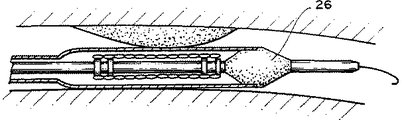
図1及び図1aを参照すると、食道内で作用する本発明による導入装置2は、末端付近に配置されたステント14を有するカテーテル4を備えている。また、該装置は、シース20を備えており、該シースは、患者の体内に挿入する間(図1)ステント14を覆う、部分22の基端方向の小径部分24を有する。該シース20は、ステント(図1a)を露出させ且つ膨張させ(矢印19)得るように退却可能である(矢印17)。カテーテルに恒久的に取り付けられた拡張先端26は、より小径部分まで末端方向テーパー付き部分28を有して、装置を体内に外傷を与えずに挿入することが出来、また、引き抜き中にプロテーゼ及び内腔に係合して、内腔を外傷を与えずに拡げることの出来る基端方向テーパー付き部分29を有する。
該カテーテル4の全長L1は約100cmであり、その外径は約3.4mmで一定である。該カテーテル4(ペンシルベニア州、フィラデルフィアのアトケム(Atochem)のデュロメータ硬さ70のピーバックス(Pebax))は、末端に設けられたハンドル12(ナイロン)と、ガイドワイヤー(例えば、0.9652mm(0.038インチ))上を追跡するための内径約1.1mmの内腔6(仮想線)とを備えている。カテーテル4は、その内腔の壁に沿ったステンレス鋼製の皮下注射チューブ(図示せず)と、柔軟なポリマー(アトケムのデュロメータ硬さ40のピーバックス)で出来た長さL2が約3cmであり、内腔壁に接触したとき、容易に撓んで外傷を与えずに進むことを可能にする、恒久的に取り付けられた可撓性の末端8とを備えることが出来る。
該カテーテル4は、身体内に導入する間に、ステンレス14を半径方向に圧縮した形態に支持する長さL3が約15cmの支持部分10を備えている。該ステント14は、ニチノール型式の材料(マサチューセッツ州、ウォータータウンのボストン・サイエンティフィック(Boston Scientific)のストレッカー・ステント(Strecker Stent))のような高弾性材料で出来た自己膨張型ステントであることが好ましい。編みステントは、ストレッカーの米国特許第4,922,905号及び1992年10月13日付けで出願された米国特許出願第07/960,584号に詳細に記載されており、これらの内容の全体は、引用して本明細書に含めてある。該ステントの膨張したときの最大径は、約20mmである。上述のように、例えば、24時間、又は48時間といった長時間に亙って壁を略正常の径まで膨張させる、一定でかなり軽い半径方向力を加えるものを選択することが出来る。該ステントは、部分10の周りに巻き付けることにより、半径方向に圧縮され、体液で劣化可能なゼラチン材料(ドイツのドイチェ・ゼラチン・ファブリケンAG(Deutsch Gelatin Fabriken AG)のDFG STOESS)を使用してこの形態にて固定される。該ステントの圧縮した形態のときの外径は約6.5mmである。カテーテルに巻き付け、ステントをゼラチンで保持することにより、ステントを圧縮する方法は、その内容の全体を引用して本明細書に含めた、1991年10月9日付けで出願された米国特許出願第07/773,847号に記載されている。また、溶融性ポリマーは、同様に引用して本明細書に含めた米国特許第5,049,138号にも記載されている。
支持部分10は、圧縮した形態にあるステントの基端及び末端の位置を標識する放射線不透過性マーカー16、16′を備えている。また、該支持部分10は、膨張した状態におけるステント14の両端を表示する放射線不透過性マーカー18、18′を備えている。
保護シース20は、カテーテル4の周りで同軸上に配置されており、身体内に導入中(図1)にステント14を伸長する。該シース20は、全長L4が約70cmであり、押出し成形による単一の可撓性ポリマー(アトケムから入手可能なデュロメータ硬さ70の押出し成形ピーバックス)で形成され、また、その肉厚は約0.5mmで一定である。該シースは、全長L5が約17cmの末端部分22を有し、この長さは、一端が多少、伸びた圧縮状態にあるステントの長さに略等しい。シースの末端部分22の外径は、約8mmであり、また、その内径は、その圧縮形態にあるステント14の径よりも僅かに大きく、シースの内壁と圧縮したステントとの間に、約0.5mmの隙間が提供される。該シース20は、末端部分22のより大径部分から基端部分の約5mmの小径部分までテーパーが付けられた、全長L6、約7−9cmのテーパー付き部分を更に備えており、該基端部分24の全長L7は、約53cmである。ハンドル25(ナイロン)は、シースを基端から退却させ(矢印17)、ステントを膨張可能に(矢印19)露出させることを可能にする(シース上のハンドル25とカテーテル上のハンドル12との間の距離は、圧縮した状態のステントの長さに略等しい)。スリット41及びプル・タブ32を有する安全スリーブ27が導入中に、ハンドルの間に位置し、ステント(図1)が誤って露出されるのを防止する。装置が適正な位置に配置されたならば、スリーブ27をカテーテルから除去し、このため、シースを退却させてステントを露出させることが出来る(図1a)。基端部分24の直径は、カテーテル本体4の外径に正確に一致するように選択する。カテーテル本体4の外径とシース20の基端部分24の内径との間の隙間は、約1.5mmである。
その半径方向寸法がその長さに沿って可変であるシースは、本発明の特別な特徴であり、このことは、曲がりくねった経路を有する内腔内で使用される大形の導入装置により、大形のステントを位置決めすることを容易にする。シースの基端部分の外径は小さいため、可撓性が増す。湾曲した外壁に加わる歪みが小さく、また、湾曲した内壁に加わる圧縮力が小さいから、該シースは、曲がりくねった通路の周りでより撓み易い。シースの全ての部分は、シース内にある構成要素の外径に正確に一致するから、全長に沿ったシースのよじれが軽減される。カテーテルの外径とシースの内径との間の空隙は小さいため、シースが湾曲部分の周りで曲がったとき、カテーテルは、比較的薄い肉厚のシースを支持する性質となる。シースの末端部分において、シースの大径部分は、カテーテルの周りに配置されたステントによって支持される。顕著によじれると、シースとカテーテルとの間に摩耗作用が生じ、その結果、シースの退却が妨げられるから、かかるよじれを最小にすることが重要である。食道のような多くの体腔において、体腔の最も曲がりくねった部分は、体内への挿入点の位置にある。本発明の装置は、可撓性を増し且つ典型的に曲がりくねった部分に沿って配置される装置の基端部分におけるよじれを特に少なくすることにより、その機能を向上させるものである。食道の典型的な寸法である約6.35mmの半径に亙り90゜曲がるならば、上述の装置のシースは、基端部分によじれを生じない。更に、基端部分における寸法の小さいシースは、より小さい寸法の内表面積を提供し、このことは、カテーテルとの摩耗作用を軽減し、このため、より平滑な作用が実現される。
特に、図2を参照すると、該装置は、全体として外傷を与えずに体腔に接触し且つ体腔を拡張させてカテーテルを先端よりも小さい狭窄部分を通じて付勢させ、狭窄部位を拡げ且つ通過するために使用することが出来るという更なる機能を果たし得る設計の拡張先端26を更に備えている。ステントを拡張させた後、先端はカテーテルを引き抜く間に内腔を拡張させ且つ/又はステントを通じて進めることを可能にする。該先端26は、全長L8が約28mmで、最大外径d1が約8mmである。先端26の最大外径は、シース20(仮想線)の末端部分22の最大外径に略等しい。該先端26は、全長L9、約12.5mmで角度θ1が約10゜の末端のテーパー付き部分28を有しており、装置を軸方向に向けて末端方向に動かしたとき、直径を漸進的に増大させる。該末端のテーパー付き部分は、その端部35における約4.5mmの径d2までテーパーが付けられており、該端部は、図示するように、外傷を与えないように丸味を付けた縁部を有する。また、該先端26は、漸進的に変化して、基端方向により小径となる外径を提供する。該先端は、角度θ2が約20゜(より小さい角度としてもよい)の基端方向テーパー付き部分29を有し、これは、引き抜き中にカテーテルを除去するとき、先端がステント及び/又は内腔に平滑に係合し且つ平滑に膨張するのに有用である。基端方向のテーパー付き部分29は、その全長L12が約4mmであり、テーパー付き部分37における約4.0mmの径d3までテーパーが付けられている。該先端は、全体として、その最大径に比べて細長く、特に、その基端領域は、最大径に比べて細長であり、漸進的な遷移部分を提供する。先端の最基端部分39は、カテーテル4(仮想線)の外径部分まで丸味が付けられている。シースの末端部分は、全長L11が約7mmで、径d4が約6.8mmの段差部分30に沿って先端26に合流する。また、該段差部分30は、20゜以下、例えば、約10゜の軽いテーパー付き部分31を有し、最大径d1までの全長L10は、約4mmである。径の異なる先端の全ての部分間の遷移部分、特に、先端の基端部部分遷移部分は、平滑である、即ち丸味が付けられており、外傷を与えない漸進的な動作を可能にし、特に、引き抜き中、部分的に膨張したステント又は体腔壁に係合するとき、引っ掛かる可能性のある鋭角な縁部が解消される。太い端部、又は鋭角な縁部が存在しない平滑な外径であること、及び丸味を付けた面である結果、カテーテルを引き抜くとき、先端がステントに引っ掛かる虞れが実質的に解消される。連続的な列状のループにより形成された編み型ステントの場合、この特徴は、特に重要なことである。最大径部分の基端方向領域及び末端方向領域の長さは、最大径に比べて相対的に長く、引き抜き中、内腔に平滑に且つ漸進的に係合して内腔を拡げる。先端26の段差部分30及びシース20(仮想線)は、体内への導入中、ステントを体液から隔離し、ステントの過早膨張の原因となる、シースの引き抜き前のゼラチンの溶融を防止するシールを形成する。
先端26は、非溶融性で比較的非圧縮性ポリマー(ドイツ、ハルのベスタミドナイロン)で形成することが出来、また、先端をカテーテルにインサート成形することにより、カテーテルに強固に取り付けることが出来る。直径約1mmの可圧縮性シリコンO−リング67を段差部分30に形成された溝(深さ約0.85mm)内に嵌め込んで、シースに対する密封効果を増すことが出来る。また、先端は、ポリエチレンで形成してもよい。
使用方法
食道に腫瘍のある患者の治療に次の方法を使用することが出来る。患者は内視鏡検査台の上で処置される。医者が直径約12mmの内視鏡を患者の口から食道に入れて、腫瘍の基端部分及び末端部分の双方を観察して、その組織及び性質を判断する。内視鏡が腫瘍を通り抜けない場合、医者はガイドワイヤーの上方を進めた剛性な拡張器により、又は内視鏡を通じて進めたバルーン拡張器により、内腔を拡張する。次に、内視鏡を後退させて、後向きにし、また、腫瘍の最末端部分を調査するようにしてその腫瘍の組成を観察する。医者は内視鏡に目盛ったセンチメートル単位の標識を使用して腫瘍の長さを測定し且つ/又は患者の切除を行う者に対して腫瘍の最末端部分を告げる。次に医者は、内視鏡の一部を引き抜き、腫瘍の最基端部分を探知し、腫瘍の長さを測定するために同様に知らせる。一般に、ステントの長さは、腫瘍の各端部を越えて約2cm伸長するように選択する。上述のように、場合により、最初に、又はその他の手段による拡張後に食道の壁が再反発した後、先端26を使用して内腔を拡げることが出来る。
一連の図3乃至図3hにおいて、患者の食道内にステントを配置した状態が示してある。図3において、患者50は、通常、直径約20mmの内腔である食道54に腫瘍52があるため、食道はその腫瘍で8乃至12mmまで狭窄しており、ガイドワイヤー56を喉から食道内に配置し、腫瘍52の末端の位置、通常、胃内まで入れることにより治療が行われる。
図3aにおいて、導入装置2は、ガイドワイヤーの基端部分をカテーテル内のガイドワイヤー内腔を通じて摺動させることにより、ガイドワイヤーの上方で導入される。潤滑剤であるK−Yゼリーをカテーテルの末端8および先端26に塗布することが出来る。次に、医者は、放射線不透過性マーカーを使用して、放射線透視装置により配置状態を観察する。図示するように、食道は、半径約6.35cmに亙って90゜の角度で曲げた部分を含む喉の丁度、末端にて、極めて曲がりくねった部分を有する。ステントを覆うシースの拡張部分22を含む装置の末端は、過度によじれずにワイヤーの湾曲部分に従うのに十分な強度を有し、その下方のステントを支持することにより、このよじれ防止効果は増す。この場合、曲がりくねった部分を通るときにシースの末端部分22が少しよじれても、シースを引き抜く位置にステントが配置されていないから、そのよじれの結果、機能が顕著に妨げられることはない。図示するように、先端26は、直径を漸進的に増大させ、外傷を与えずに装置を食道内に進めることを可能にする。
図3b及び図3c(円cで囲った領域の拡大図)において、ステント及びシースの拡張部分22の位置に対応した装置の末端部分が、腫瘍52に起因する狭窄部分を通り抜け得るように配置されている。この位置にあるとき、シースの小径部分24を含む装置の部分は、最初の湾曲部分の周りで容易に曲がる。より大径部分まで漸進的に遷移する先端26は、狭小領域を通り抜けるのに役立つ。上述のように、該先端を使用して領域を付勢して開けることが出来る。
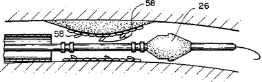
図3d乃至図3hにおいて、作用を更に示すべく狭窄領域の拡大図が示してある。特に、図3dにおいて、ステントは、狭窄部分の周りに適正に配置されており、シースは、軸方向に向けて基端方向に慴動して、ステントを体腔に露出させる。ステントを圧縮した形態に保持するゼラチンは、大家器により溶融し、ステントは、より大径部分まで自然に膨張する。図示するように、多くの場合において、ステントは最初に狭窄部分を少しだけ膨張させ、くびれた狭窄部分は、先端26の最大の半径方法寸法よりも多少小さい半径方向を有するかなり狭小な通路を提供する。狭窄部分における最初の開口部は、上述のように、拡張手段により形成し、その開口部が最初は十分に大きく、装置が多少の隙間を伴って通り抜けることを可能にする。しかしながら、食道壁の再反発動作により装置が通り抜けたならば、開口部は、多少小さくすることが出来る。ある場合には、外傷を与えない先端を有する装置を使用して、狭窄部分を僅かに拡げ、装置が通り抜け得るようにすることが出来る。更に、ステントは、カテーテルから解放したときにその一部が拡がって、ひだ部分58が残って内腔の一部を閉鎖するようにする。こうした全ての状態は、内腔の狭窄領域よりも先端の寸法の方が大きい状況を提供する。
図3eにおいて、こうした状態にてカテーテルを引き抜くと、先端26の基端部分は狭窄領域にてステントに係合する。より大径部分まで平滑に漸進的に変化する外形であること、及び丸味を付けた遷移部分であるため、先端を基端方向に引っ張ったとき、先端がステントに引っ掛かったり、又はステントに拘束されることが防止される。
図3fにおいて、カテーテルの引き抜きを続けると、先端の基端部分は体腔及びステントを膨張させるか(矢印61)、又はステントのひだ部分を邪魔にならない位置まで平滑に押し出すか、或いは、その双方により、より大きい通路を形成し、先端が貫通し、カテーテルが引き抜かれるようにすることにより、狭小領域の全体の通路を漸進的に拡張する。
図3g及び図3hにおいて、短い時間後にステントにより提供される半径方向力が食道を更に拡げて、飲み込み動作を容易にする大きく開放した内腔を提供する。
その他の実施例
その他の多数の実施例が可能である。例えば、先端の最大径は、圧縮状態にあるステントの径よりもはるかに大きく、ステントを膨張させる前に先端が内腔を所望の径まで拡張させ得るような寸法とすることが出来る。シースは、先端を使用して内腔を拡げるとき、押し進め易さ、又は引張り易さを改善し得るように変更を加えることが出来る。該先端は、カテーテルと一体に形成することが出来る。導入装置は、各種の体腔、プロテーゼ、尿管又は、総胆管、脾管、左右の肝管を含む胆管樹に使用し得る形態とされ、食道、胃、柔毛のある小腸、結腸又は直腸のような消化管内腔に使用するときに特に、有利である。理解され得るように、後者の適用例の殆どは、約1乃至1.5cm以上の相対的に大きい内腔を含み、よじれに抵抗する大形で可撓性の導入装置により、比較的大形のステントを導入することを必要とする曲がりくねった部分を有するものを含む。上述のように、本発明の形態は、最大径が6mm以上の大形の導入装置を使用して、膨張径が約10mm以上の大形のステントを導入する場合に特に有利である。食道と同様に、こうした内腔の殆どは、結腸における直腸のS状結腸のような導入装置の挿入箇所付近にて極端に大きい曲率を有する。上記に詳細に説明した構造体において、ステントは、自己膨張型であり、ゼラチンを使用して圧縮状態に保持されるが、その他の実施例は、ゼラチンを使用せずに、ステントを圧縮形態に保持するシースを使用する。例えば、該シースは、末端部分に肉厚の薄い部分を有し、基礎部分に肉厚の部分を有するようにして、ステントを圧縮状態に保持する構造とすることが出来る。シースは、加熱することにより基端部分の縮小径とした、ポリエチレン収縮管を使用する等により、各種の寸法で形成することが可能である。かかる場合、管の肉厚は基端部分にて厚くなるが、そのため、強度を増すことが出来る。また、本発明の有利な点は、バルーン膨張可能なステントのような自己膨張型ではないステントでも達成することが出来る。食塩水のような流体を内腔内に流して、体液の溶融成分をより迅速に溶融させることが出来る。更に別の実施例は、請求の範囲に包含される。FIELD OF THE INVENTION The present invention relates to a device for introducing a prosthesis into the body.
BACKGROUND OF THE INVENTION Prostheses, such as stents, implants, etc., are implanted in the body to improve the function of body cavities. For example, a stent having considerable elasticity can be used to apply radial force to a constricted portion of the lumen wall to open the lumen to near normal dimensions.
Such a stent can be introduced into a body cavity using a device comprising a catheter, which supports the stent near its distal end and is disposed coaxially around the catheter and above the stent. A sheath to prevent abrasion of the stent and body wall as the catheter is advanced through tortuous body passages; The catheter has an expanded tip adjacent the distal end of the stent, which also helps to atraumaticize the device and protects the stent.
Once the stent has been placed in the stenotic portion of the lumen, the sheath is removed, exposing the stent, and the stent can expand and contact the lumen wall. Thereafter, the catheter is removed from the body by pulling the catheter proximally through the large lumen formed by the inflated prosthesis remaining in the body.
SUMMARY OF THE INVENTION The present invention provides a device for introducing a prosthesis having a distal end configured to facilitate entry into the body and removal from the body after the prosthesis is inflated. The tip has a distal taper that can expand smoothly during advancement when the lumen is narrower than the tip, and expands more smoothly when the prosthesis retracts in a situation where the lumen does not immediately inflate, A proximal taper that provides clearance for a large diameter tip. The features of the following forms can be combined in various ways.
In one aspect, the invention features an apparatus for introducing a prosthesis into a patient. The device includes a proximal end, a distal end that remains outside the body, a support portion that supports the prosthesis in a radially compressed configuration so that the prosthesis can be introduced to a desired location within the body, and a distally extending distal end of the prosthesis. And an elongated catheter having: The distal end has a maximum diameter substantially equal to or greater than the radially compressed prosthesis, and the distal end has a distal portion that smoothly extends in the distal direction to a smaller diameter, and a proximal direction. And has a proximal end portion that facilitates withdrawal after the stent has been expanded and has a smaller diameter.
Further, various forms having one or more of the following features can be adopted. The distal and proximal portions of the distal end are tapered to smaller diameter portions. The distal end is formed with a proximal taper at an angle of 20 ° or less. The tip has a smooth shape at the proximal end without sharp edges. The prosthesis is expandable to a diameter less than or equal to the maximum diameter of the distal end, and the proximal portion of the distal end engages the prosthesis when the catheter is withdrawn proximally, expanding the passage through the prosthesis, and Can be removed. The proximal portion has a taper of about 20 ° or less. The maximum diameter of the tip is about 8 mm. The proximal and distal portions have an axial length greater than the maximum diameter of the distal end. The tip has a transition region between portions having different diameters, and the transition region is formed smoothly without a sharp edge. The prosthesis is self-expandable. The device has a retractable protective sheath located above the prosthesis, the protective sheath engaging a tip during introduction into the body to protect a seal that protects the prosthesis from exposure to bodily fluids. Form. The protective sheath engages the tip in a stepped region having portions that transition smoothly to different diameters. The protective sheath has a flexible proximal portion that is smaller in diameter during introduction into the body than a distal portion located above the sheath.
In another aspect, the invention is directed to a method of introducing a prosthesis into a patient, wherein the elongated portion has a proximal end that remains outside the body, a distal end, and a support portion that supports the prosthesis in a radially compressed configuration. Providing a distal end of the support portion and further having a diameter substantially equal to or greater than the radially compressed prosthesis, wherein the catheter has a smaller diameter portion. And a proximal portion that smoothly extends in the proximal direction to a smaller diameter portion and that facilitates withdrawal after the stent is expanded to expand the stent. The method also includes disposing the catheter in a body cavity, positioning the prosthesis at a desired location, inflating the prosthesis to a diameter less than or equal to the maximum diameter of the distal end, and withdrawing the catheter to remove the proximal end of the distal end. Engaging the portion and the prosthesis, and expanding the passageway through the prosthesis with the tip to continue withdrawing the catheter so that the catheter can be removed from the body.
Further, various modes of the present invention having one or more of the following features can be adopted. The method includes selecting a self-expanding prosthesis after a long period of time to apply an axial force inside the lumen to completely expand the lumen, and withdrawing the catheter before fully expanding the prosthesis. And stages. The direction includes the step of pressing the distal or proximal portion of the distal end against the region to expand the region so that it can pass through a lumen region having a diameter smaller than the maximum diameter of the constricted distal end. I have.
The present invention has a number of advantages. For example, because the catheter can be easily removed from the body, the physician does not have to wait for the prosthesis to expand to a larger radial dimension than the tip, and also dilates the lumen so that the catheter can be removed. There is also no need to use a separate dilatation catheter to do so. The device according to the invention allows the physician to select a prosthesis that also allows the lumen to expand as slowly as predetermined over hours or days, which has been weakened by the tumor. It is possible to obtain a therapeutically advantageous effect of preventing the lumen wall from being broken. Immediately after releasing the slow inflating prosthesis, the catheter can be removed from the body. The device can be used to widen the lumen while advancing into the lumen, thereby reducing the need to use another device to pre-dilate the lumen.
Other features and advantages are described below.
[Brief description of the drawings]
First, the drawings will be briefly described.
1 is a cross-sectional side view of a device according to the present invention in a form that can be introduced into the body, FIG. 1a is a similar view of the device according to an alternative form,
FIG. 2 is a detailed side view of the expanding tip,
3 to 3h show a situation in which the device according to the invention places the stent in the patient's esophagus.
DESCRIPTION OF THE PREFERRED EMBODIMENT Referring to FIGS. 1 and 1a, an
Overall length L 1 of the catheter 4 is about 100 cm, an outer diameter is constant at about 3.4 mm. The catheter 4 (Pebax with a durometer of 70 from Atochem, Philadelphia, PA) has a handle 12 (nylon) at the end and a guide wire (eg, 0.038 inch). )) A lumen 6 (virtual line) having an inner diameter of about 1.1 mm for tracking the upper side. The catheter 4, and its lumen stainless steel hypodermic tubing along the wall (not shown), flexible polymer length L 2 of about 3cm made of (peak Bucks durometer hardness 40 of Atochem) And can have a permanently attached
The catheter 4, during the introduction into the body, the length L 3 which supports the form obtained by compressing
The
A
A sheath whose radial dimension is variable along its length is a particular feature of the invention, which is largely due to the large introducer used in the lumen having a tortuous path. Facilitates positioning of shaped stents. Since the outer diameter of the proximal end portion of the sheath is small, flexibility is increased. The sheath is more flexible around tortuous passages due to less distortion on the curved outer wall and less compression on the curved inner wall. All parts of the sheath exactly match the outer diameter of the components within the sheath, thus reducing kinking of the sheath along its entire length. Because the gap between the outer diameter of the catheter and the inner diameter of the sheath is small, when the sheath bends around a curved portion, the catheter has the property of supporting a relatively thin-walled sheath. At the distal end of the sheath, the large diameter portion of the sheath is supported by a stent disposed around the catheter. It is important to minimize such kinking, as significant kinking creates a wear effect between the sheath and the catheter, thereby preventing retraction of the sheath. In many body cavities, such as the esophagus, the most tortuous portion of the body cavity is at the point of insertion into the body. The device of the present invention enhances its function by increasing flexibility and particularly reducing kink at the proximal portion of the device, which is typically located along a tortuous portion. If it bends 90 ° over a radius of about 6.35 mm, a typical dimension of the esophagus, the sheath of the device described above will not buckle at the proximal portion. In addition, the smaller size sheath at the proximal portion provides a smaller size internal surface area, which reduces the wear effect on the catheter, thus providing a smoother effect.
In particular, with reference to FIG. 2, the device is generally trauma free to contact and dilate the body cavity to urge the catheter through a stenosis smaller than the tip to expand and pass the stenosis. It further includes an extended
The
Methods of Use The following methods can be used to treat patients with esophageal tumors. The patient is treated on an endoscopy table. A physician places an endoscope about 12 mm in diameter through the patient's mouth into the esophagus and observes both the proximal and distal portions of the tumor to determine its tissue and nature. If the endoscope does not pass through the tumor, the physician dilates the lumen with a rigid dilator advanced over the guidewire or with a balloon dilator advanced through the endoscope. Next, the endoscope is retracted and turned back, and the composition of the tumor is observed, such as by examining the extreme end of the tumor. The physician measures the length of the tumor using centimeter markings on the endoscope and / or tells the person performing the resection of the patient the most distal portion of the tumor. The physician then withdraws a portion of the endoscope, locates the proximal-most portion of the tumor, and signals similarly to measure the length of the tumor. Generally, the length of the stent is chosen to extend about 2 cm beyond each end of the tumor. As described above, the
A series of FIGS. 3 to 3h show a stent deployed in the patient's esophagus. In FIG. 3, the
In FIG. 3a, the
In FIGS. 3b and 3c (enlarged view of the area surrounded by circle c), the distal end of the device corresponding to the position of the stent and
3d to 3h, enlarged views of the stenosis region are shown to further illustrate the operation. In particular, in FIG. 3d, the stent is properly positioned around the stenosis, and the sheath slides axially proximally to expose the stent to the body cavity. Gelatin, which holds the stent in its compressed form, melts in the large vessel and the stent expands spontaneously to a larger diameter. As shown, in many cases, the stent initially expands the stenosis only slightly, with the constricted stenosis providing a fairly narrow passage having a radial direction that is slightly less than the maximum radial method dimension of the
In FIG. 3e, when the catheter is withdrawn in such a state, the proximal portion of the
In FIG. 3f, with continued withdrawal of the catheter, the proximal portion of the distal end may expand the body lumen and stent (arrow 61) and / or push the folds of the stent smoothly out of the way, or both. , To progressively dilate the entire passageway of the narrow area by creating a larger passageway, allowing the tip to penetrate and the catheter to be withdrawn.
3g and 3h, the radial force provided by the stent after a short period of time further widens the esophagus, providing a large open lumen to facilitate swallowing.
Other Embodiments Many other embodiments are possible. For example, the maximum diameter of the tip can be much larger than the diameter of the stent in a compressed state, and can be sized so that the tip can expand the lumen to the desired diameter before expanding the stent. The sheath can be modified as the tip is used to expand the lumen to improve pushability or pullability. The tip can be formed integrally with the catheter. The introduction device is in a form that can be used for various body cavities, prostheses, ureters or bile duct trees including the common bile duct, splenic duct, left and right hepatic ducts, and is used for the esophagus, stomach, small intestine with fur, colon or rectum It is particularly advantageous when used in such a gastrointestinal lumen. As can be appreciated, most of the latter applications involve a relatively large lumen of about 1 to 1.5 cm or more, and a relatively large, flexible introducer that resists kinking and is relatively large. Includes those with serpentine portions that require the introduction of a stent. As mentioned above, embodiments of the present invention are particularly advantageous when using a large introducer with a maximum diameter of 6 mm or more to introduce a large stent with an expanded diameter of about 10 mm or more. Like the esophagus, most of these lumens have extremely large curvature near the insertion point of the introducer, such as the sigmoid colon of the rectum in the colon. In the structure described in detail above, the stent is self-expanding and is held in a compressed state using gelatin, but other embodiments do not use gelatin and place the stent in a compressed form. Use a holding sheath. For example, the sheath may have a thinned portion at the distal end and a thickened portion at the base portion to hold the stent in a compressed state. The sheath can be formed in various dimensions, for example, by reducing the diameter of the base portion by heating, using a polyethylene shrink tube, or the like. In such a case, the wall thickness of the tube is increased at the base end portion, so that the strength can be increased. Also, the advantages of the present invention can be achieved with a stent that is not self-expanding, such as a balloon-expandable stent. A fluid, such as saline, can be flowed into the lumen to more rapidly melt the molten component of the bodily fluid. Still other embodiments are within the following claims.
Claims (25)
軸線を画成しかつ人体の外側に留まる基端、末端、及びプロテーゼを体内の所望の位置まで導入するように半径方向に圧縮した形態のプロテーゼを支持する支持部分を有するカテーテル軸を備えた長いカテーテルと、
前記カテーテルに支持されたプロテーゼと、
末端及び基端を有する、壁が薄く引き込み可能な防護用のシースであって、前記所望の位置に導入する間、前記半径方向に収縮した形態で前記カテーテルに支持されているとき前記プロテーゼの周りに同軸状に配置される、前記シースと、
前記プロテーゼの末端で前記カテーテルに固定された先端であって、末端部分、基端部分及びそれらの間に配置された最大径の部分を有する、前記先端と、を備え、
前記最大径の部分が前記半径方向に圧縮した形態のプロテーゼと等しいか又はそれより大きい直径を有し、
前記末端部分が小さい直径の部分まで軸線に沿って末端方向に伸長しかつ滑らかな外形を有し、前記末端部分の軸線方向長さが前記先端の最大径の部分の直径よりも大きく、
前記基端部分が小さい直径の部分まで軸線に沿って基端方向に伸長しかつ滑らかな外形を有し、前記基端部分の軸線方向長さが前記先端の最大径の部分の直径よりも大きく、前記先端の基端部分が軸線に沿って一定の直径の段差領域を備え、前記段差領域が前記シースの末端の内径に対応する直径を有し、それにより、前記シースの末端が前記プロテーゼの上に亘り延在しているとき、前記シースの末端が前記段差領域と係合するようにした、装置。A device to introduce the prosthesis into the patient's body,
An elongated catheter shaft having a proximal end defining an axis and remaining outside the body, a distal end, and a catheter shaft having a support portion for supporting the prosthesis in a radially compressed configuration to introduce the prosthesis to a desired location within the body. A catheter,
A prosthesis supported by the catheter,
A thin-walled retractable protective sheath having a distal end and a proximal end, around the prosthesis when supported on the catheter in the radially contracted configuration during introduction into the desired location; The sheath is disposed coaxially with the sheath,
A distal end secured to the catheter at a distal end of the prosthesis, the distal end having a distal portion, a proximal portion, and a portion of the largest diameter disposed therebetween.
The largest diameter portion has a diameter equal to or greater than the radially compressed form of the prosthesis;
The distal portion extends distally along the axis to a smaller diameter portion and has a smooth profile, wherein the axial length of the distal portion is greater than the diameter of the largest diameter portion of the tip;
The proximal portion extends proximally along the axis to a portion of smaller diameter and has a smooth outer shape, wherein the axial length of the proximal portion is greater than the diameter of the largest diameter portion of the distal end. The proximal portion of the distal end includes a stepped region of constant diameter along the axis, the stepped region having a diameter corresponding to the inner diameter of the distal end of the sheath, whereby the distal end of the sheath is The device wherein the distal end of the sheath is engaged with the step region when extending thereover.
Applications Claiming Priority (5)
| Application Number | Priority Date | Filing Date | Title |
|---|---|---|---|
| US4623793A | 1993-04-13 | 1993-04-13 | |
| US08/046,237 | 1993-04-13 | ||
| US4828793A | 1993-04-14 | 1993-04-14 | |
| US08/048,287 | 1993-04-14 | ||
| PCT/US1994/003942 WO1994023669A1 (en) | 1993-04-13 | 1994-04-11 | Prosthesis delivery system with dilating tip |
Publications (2)
| Publication Number | Publication Date |
|---|---|
| JPH09500036A JPH09500036A (en) | 1997-01-07 |
| JP3553067B2 true JP3553067B2 (en) | 2004-08-11 |
Family
ID=26723698
Family Applications (1)
| Application Number | Title | Priority Date | Filing Date |
|---|---|---|---|
| JP52336294A Expired - Fee Related JP3553067B2 (en) | 1993-04-13 | 1994-04-11 | Prosthesis introduction device with extended tip |
Country Status (5)
| Country | Link |
|---|---|
| US (2) | US5902333A (en) |
| EP (1) | EP0702535B1 (en) |
| JP (1) | JP3553067B2 (en) |
| DE (1) | DE69431989T2 (en) |
| WO (1) | WO1994023669A1 (en) |
Families Citing this family (109)
| Publication number | Priority date | Publication date | Assignee | Title |
|---|---|---|---|---|
| US5749848A (en) * | 1995-11-13 | 1998-05-12 | Cardiovascular Imaging Systems, Inc. | Catheter system having imaging, balloon angioplasty, and stent deployment capabilities, and method of use for guided stent deployment |
| US7004962B2 (en) | 1998-07-27 | 2006-02-28 | Schneider (Usa), Inc. | Neuroaneurysm occlusion and delivery device and method of using same |
| US6613075B1 (en) * | 1999-10-27 | 2003-09-02 | Cordis Corporation | Rapid exchange self-expanding stent delivery catheter system |
| US20010049547A1 (en) * | 2000-02-04 | 2001-12-06 | Moore Scott T. | Stent introducer apparatus |
| US6808534B1 (en) | 2000-02-16 | 2004-10-26 | Endovascular Technologies, Inc. | Collapsible jacket guard |
| US9173658B2 (en) * | 2000-03-06 | 2015-11-03 | Covidien Lp | Apparatus and method for performing a bypass procedure in a digestive system |
| WO2001095976A1 (en) * | 2000-06-09 | 2001-12-20 | Children's Hospital & Health Center Of San Diego | Stent delivery system |
| US20020016597A1 (en) * | 2000-08-02 | 2002-02-07 | Dwyer Clifford J. | Delivery apparatus for a self-expanding stent |
| US6773446B1 (en) | 2000-08-02 | 2004-08-10 | Cordis Corporation | Delivery apparatus for a self-expanding stent |
| DE10105592A1 (en) | 2001-02-06 | 2002-08-08 | Achim Goepferich | Placeholder for drug release in the frontal sinus |
| DE10118944B4 (en) * | 2001-04-18 | 2013-01-31 | Merit Medical Systems, Inc. | Removable, essentially cylindrical implants |
| DE10148185B4 (en) | 2001-09-28 | 2005-08-11 | Alveolus, Inc. | Instrument for implanting vascular prostheses |
| US7169170B2 (en) | 2002-02-22 | 2007-01-30 | Cordis Corporation | Self-expanding stent delivery system |
| US20030236565A1 (en) * | 2002-06-21 | 2003-12-25 | Dimatteo Kristian | Implantable prosthesis |
| US20040006380A1 (en) * | 2002-07-05 | 2004-01-08 | Buck Jerrick C. | Stent delivery system |
| CA2494702A1 (en) * | 2002-08-02 | 2004-02-12 | Auxetica Limited | Auxetic tubular liners |
| US7033384B2 (en) * | 2002-08-30 | 2006-04-25 | Satiety, Inc. | Stented anchoring of gastric space-occupying devices |
| US8317816B2 (en) | 2002-09-30 | 2012-11-27 | Acclarent, Inc. | Balloon catheters and methods for treating paranasal sinuses |
| US20040093056A1 (en) * | 2002-10-26 | 2004-05-13 | Johnson Lianw M. | Medical appliance delivery apparatus and method of use |
| US7309349B2 (en) * | 2003-01-23 | 2007-12-18 | Cordis Corporation | Friction reducing lubricant for stent loading and stent delivery systems |
| JP2006519654A (en) * | 2003-03-10 | 2006-08-31 | ウィルソン−クック・メディカル・インコーポレーテッド | Stent introducer device |
| US7637934B2 (en) * | 2003-03-31 | 2009-12-29 | Merit Medical Systems, Inc. | Medical appliance optical delivery and deployment apparatus and method |
| US7604660B2 (en) | 2003-05-01 | 2009-10-20 | Merit Medical Systems, Inc. | Bifurcated medical appliance delivery apparatus and method |
| US20050010138A1 (en) * | 2003-07-11 | 2005-01-13 | Mangiardi Eric K. | Lumen-measuring devices and method |
| JP2007501661A (en) * | 2003-08-07 | 2007-02-01 | アルヴィオラス,インコーポレイテッド | Medical instrument, delivery device and method of use |
| US7208008B2 (en) * | 2003-10-02 | 2007-04-24 | Medtronic Vascular, Inc. | Balloonless direct stenting device |
| US7361168B2 (en) | 2004-04-21 | 2008-04-22 | Acclarent, Inc. | Implantable device and methods for delivering drugs and other substances to treat sinusitis and other disorders |
| US9351750B2 (en) | 2004-04-21 | 2016-05-31 | Acclarent, Inc. | Devices and methods for treating maxillary sinus disease |
| US8894614B2 (en) | 2004-04-21 | 2014-11-25 | Acclarent, Inc. | Devices, systems and methods useable for treating frontal sinusitis |
| US8747389B2 (en) | 2004-04-21 | 2014-06-10 | Acclarent, Inc. | Systems for treating disorders of the ear, nose and throat |
| US9101384B2 (en) | 2004-04-21 | 2015-08-11 | Acclarent, Inc. | Devices, systems and methods for diagnosing and treating sinusitis and other disorders of the ears, Nose and/or throat |
| US7559925B2 (en) | 2006-09-15 | 2009-07-14 | Acclarent Inc. | Methods and devices for facilitating visualization in a surgical environment |
| US7419497B2 (en) | 2004-04-21 | 2008-09-02 | Acclarent, Inc. | Methods for treating ethmoid disease |
| US8764729B2 (en) | 2004-04-21 | 2014-07-01 | Acclarent, Inc. | Frontal sinus spacer |
| US7654997B2 (en) | 2004-04-21 | 2010-02-02 | Acclarent, Inc. | Devices, systems and methods for diagnosing and treating sinusitus and other disorders of the ears, nose and/or throat |
| US10188413B1 (en) | 2004-04-21 | 2019-01-29 | Acclarent, Inc. | Deflectable guide catheters and related methods |
| US20190314620A1 (en) | 2004-04-21 | 2019-10-17 | Acclarent, Inc. | Apparatus and methods for dilating and modifying ostia of paranasal sinuses and other intranasal or paranasal structures |
| US20060004323A1 (en) | 2004-04-21 | 2006-01-05 | Exploramed Nc1, Inc. | Apparatus and methods for dilating and modifying ostia of paranasal sinuses and other intranasal or paranasal structures |
| US20070208252A1 (en) | 2004-04-21 | 2007-09-06 | Acclarent, Inc. | Systems and methods for performing image guided procedures within the ear, nose, throat and paranasal sinuses |
| US7410480B2 (en) | 2004-04-21 | 2008-08-12 | Acclarent, Inc. | Devices and methods for delivering therapeutic substances for the treatment of sinusitis and other disorders |
| US7803150B2 (en) | 2004-04-21 | 2010-09-28 | Acclarent, Inc. | Devices, systems and methods useable for treating sinusitis |
| US8702626B1 (en) | 2004-04-21 | 2014-04-22 | Acclarent, Inc. | Guidewires for performing image guided procedures |
| US9089258B2 (en) | 2004-04-21 | 2015-07-28 | Acclarent, Inc. | Endoscopic methods and devices for transnasal procedures |
| US9399121B2 (en) | 2004-04-21 | 2016-07-26 | Acclarent, Inc. | Systems and methods for transnasal dilation of passageways in the ear, nose or throat |
| US8932276B1 (en) | 2004-04-21 | 2015-01-13 | Acclarent, Inc. | Shapeable guide catheters and related methods |
| US20070167682A1 (en) | 2004-04-21 | 2007-07-19 | Acclarent, Inc. | Endoscopic methods and devices for transnasal procedures |
| US7462175B2 (en) | 2004-04-21 | 2008-12-09 | Acclarent, Inc. | Devices, systems and methods for treating disorders of the ear, nose and throat |
| US20060063973A1 (en) | 2004-04-21 | 2006-03-23 | Acclarent, Inc. | Methods and apparatus for treating disorders of the ear, nose and throat |
| US8146400B2 (en) | 2004-04-21 | 2012-04-03 | Acclarent, Inc. | Endoscopic methods and devices for transnasal procedures |
| US9554691B2 (en) | 2004-04-21 | 2017-01-31 | Acclarent, Inc. | Endoscopic methods and devices for transnasal procedures |
| US7955371B2 (en) * | 2004-05-12 | 2011-06-07 | Medtronic Vascular, Inc. | System and method for stent deployment and infusion of a therapeutic agent into tissue adjacent to the stent ends |
| US9480589B2 (en) * | 2005-05-13 | 2016-11-01 | Boston Scientific Scimed, Inc. | Endoprosthesis delivery system |
| US8951225B2 (en) | 2005-06-10 | 2015-02-10 | Acclarent, Inc. | Catheters with non-removable guide members useable for treatment of sinusitis |
| US8114113B2 (en) | 2005-09-23 | 2012-02-14 | Acclarent, Inc. | Multi-conduit balloon catheter |
| US20070233221A1 (en) * | 2006-03-31 | 2007-10-04 | The Board Of Regents, The University Of Texas System | Esophageal dilation and stent delivery system and method of use |
| US8190389B2 (en) | 2006-05-17 | 2012-05-29 | Acclarent, Inc. | Adapter for attaching electromagnetic image guidance components to a medical device |
| US8136711B2 (en) | 2006-09-08 | 2012-03-20 | Tyco Healthcare Group Lp | Dissection tip and introducer for surgical instrument |
| US8403196B2 (en) | 2006-09-08 | 2013-03-26 | Covidien Lp | Dissection tip and introducer for surgical instrument |
| US9820688B2 (en) | 2006-09-15 | 2017-11-21 | Acclarent, Inc. | Sinus illumination lightwire device |
| US8439687B1 (en) | 2006-12-29 | 2013-05-14 | Acclarent, Inc. | Apparatus and method for simulated insertion and positioning of guidewares and other interventional devices |
| US8814930B2 (en) | 2007-01-19 | 2014-08-26 | Elixir Medical Corporation | Biodegradable endoprosthesis and methods for their fabrication |
| WO2008124787A2 (en) | 2007-04-09 | 2008-10-16 | Acclarent, Inc. | Ethmoidotomy system and implantable spacer devices having therapeutic substance delivery capability for treatment of paranasal sinusitis |
| US8118757B2 (en) | 2007-04-30 | 2012-02-21 | Acclarent, Inc. | Methods and devices for ostium measurement |
| US8485199B2 (en) | 2007-05-08 | 2013-07-16 | Acclarent, Inc. | Methods and devices for protecting nasal turbinate during surgery |
| DE102007040868A1 (en) * | 2007-08-29 | 2009-04-16 | Innora Gmbh | Balloon catheter with protection against unfolding |
| US9597080B2 (en) * | 2007-09-24 | 2017-03-21 | Covidien Lp | Insertion shroud for surgical instrument |
| US10206821B2 (en) | 2007-12-20 | 2019-02-19 | Acclarent, Inc. | Eustachian tube dilation balloon with ventilation path |
| US8182432B2 (en) | 2008-03-10 | 2012-05-22 | Acclarent, Inc. | Corewire design and construction for medical devices |
| MX2011001099A (en) | 2008-07-30 | 2011-03-15 | Acclarent Inc | Paranasal ostium finder devices and methods. |
| JP5584687B2 (en) | 2008-09-18 | 2014-09-03 | アクラレント インコーポレイテッド | Method and apparatus for treating ear, nose and throat disorders |
| US20100241155A1 (en) | 2009-03-20 | 2010-09-23 | Acclarent, Inc. | Guide system with suction |
| US7978742B1 (en) | 2010-03-24 | 2011-07-12 | Corning Incorporated | Methods for operating diode lasers |
| US8435290B2 (en) | 2009-03-31 | 2013-05-07 | Acclarent, Inc. | System and method for treatment of non-ventilating middle ear by providing a gas pathway through the nasopharynx |
| JP5284165B2 (en) * | 2009-03-31 | 2013-09-11 | テルモ株式会社 | Biological organ lesion improvement device |
| GB2469506B (en) * | 2009-04-16 | 2011-05-18 | Cook William Europ | Stent introducer apparatus |
| EP2496189A4 (en) | 2009-11-04 | 2016-05-11 | Nitinol Devices And Components Inc | Alternating circumferential bridge stent design and methods for use thereof |
| JP5061325B2 (en) * | 2010-03-05 | 2012-10-31 | セブン ドリーマーズ ラボラトリーズ,インコーポレイテッド | Pharyngeal dilation device |
| US8864811B2 (en) | 2010-06-08 | 2014-10-21 | Veniti, Inc. | Bi-directional stent delivery system |
| US9301864B2 (en) | 2010-06-08 | 2016-04-05 | Veniti, Inc. | Bi-directional stent delivery system |
| US9155492B2 (en) | 2010-09-24 | 2015-10-13 | Acclarent, Inc. | Sinus illumination lightwire device |
| US9233014B2 (en) | 2010-09-24 | 2016-01-12 | Veniti, Inc. | Stent with support braces |
| EP2624791B1 (en) | 2010-10-08 | 2017-06-21 | Confluent Medical Technologies, Inc. | Alternating circumferential bridge stent design |
| JP5717592B2 (en) * | 2011-08-31 | 2015-05-13 | Junken Medical株式会社 | Tubular organ treatment device |
| US9554904B2 (en) * | 2011-09-28 | 2017-01-31 | Medtronic CV Luxembourg S.a.r.l. | Distal tip assembly for a heart valve delivery catheter |
| US9010608B2 (en) | 2011-12-14 | 2015-04-21 | Covidien Lp | Releasable buttress retention on a surgical stapler |
| US9486349B2 (en) * | 2012-08-10 | 2016-11-08 | W. L. Gore & Associates, Inc. | Systems and methods of deployment of endoluminal devices |
| WO2014115273A1 (en) * | 2013-01-23 | 2014-07-31 | テルモ株式会社 | Self-expanding stent system |
| US9936951B2 (en) | 2013-03-12 | 2018-04-10 | Covidien Lp | Interchangeable tip reload |
| US9433437B2 (en) | 2013-03-15 | 2016-09-06 | Acclarent, Inc. | Apparatus and method for treatment of ethmoid sinusitis |
| US9629684B2 (en) | 2013-03-15 | 2017-04-25 | Acclarent, Inc. | Apparatus and method for treatment of ethmoid sinusitis |
| CN103271786B (en) * | 2013-04-01 | 2015-11-18 | 珠海成富医疗器材有限公司 | Visual support releaser |
| US9700312B2 (en) | 2014-01-28 | 2017-07-11 | Covidien Lp | Surgical apparatus |
| US9259339B1 (en) | 2014-08-15 | 2016-02-16 | Elixir Medical Corporation | Biodegradable endoprostheses and methods of their fabrication |
| US9730819B2 (en) | 2014-08-15 | 2017-08-15 | Elixir Medical Corporation | Biodegradable endoprostheses and methods of their fabrication |
| US9480588B2 (en) | 2014-08-15 | 2016-11-01 | Elixir Medical Corporation | Biodegradable endoprostheses and methods of their fabrication |
| US9855156B2 (en) | 2014-08-15 | 2018-01-02 | Elixir Medical Corporation | Biodegradable endoprostheses and methods of their fabrication |
| US11622872B2 (en) | 2016-05-16 | 2023-04-11 | Elixir Medical Corporation | Uncaging stent |
| EP3861961A1 (en) | 2016-05-16 | 2021-08-11 | Elixir Medical Corporation | Uncaging stent |
| WO2018005628A1 (en) | 2016-06-29 | 2018-01-04 | Boston Scientific Scimed, Inc. | Stent delivery system |
| US10905853B2 (en) | 2017-01-17 | 2021-02-02 | DePuy Synthes Products, Inc. | System and method for delivering a catheter |
| EP3612140B1 (en) * | 2017-04-21 | 2024-05-01 | Merit Medical Systems, Inc. | Deployable stents and related devices, and systems |
| WO2018200716A1 (en) | 2017-04-26 | 2018-11-01 | Boston Scientific Scimed, Inc. | Proximal and distal release delivery system |
| US10441449B1 (en) | 2018-05-30 | 2019-10-15 | Vesper Medical, Inc. | Rotary handle stent delivery system and method |
| US10449073B1 (en) | 2018-09-18 | 2019-10-22 | Vesper Medical, Inc. | Rotary handle stent delivery system and method |
| US11666464B2 (en) | 2019-01-28 | 2023-06-06 | Tensor Flow Ventures Llc | Magnetic stent and stent delivery |
| US20200237540A1 (en) * | 2019-01-28 | 2020-07-30 | Spiros Manolidis | Stent delivery for vascular surgery |
| US11850149B2 (en) * | 2020-03-05 | 2023-12-26 | Brandon Walsh | Prosthetic heart valve delivery system |
| US11219541B2 (en) | 2020-05-21 | 2022-01-11 | Vesper Medical, Inc. | Wheel lock for thumbwheel actuated device |
| CN115737010B (en) * | 2022-12-09 | 2024-04-19 | 上海珩畅医疗科技有限公司 | Dilator for interventional therapy equipment |
Family Cites Families (62)
| Publication number | Priority date | Publication date | Assignee | Title |
|---|---|---|---|---|
| US1878671A (en) * | 1929-07-02 | 1932-09-20 | John Murray | Dilator |
| US2701559A (en) * | 1951-08-02 | 1955-02-08 | William A Cooper | Apparatus for exfoliating and collecting diagnostic material from inner walls of hollow viscera |
| US3334629A (en) * | 1964-11-09 | 1967-08-08 | Bertram D Cohn | Occlusive device for inferior vena cava |
| US3540431A (en) * | 1968-04-04 | 1970-11-17 | Kazi Mobin Uddin | Collapsible filter for fluid flowing in closed passageway |
| US3638649A (en) * | 1969-07-07 | 1972-02-01 | Univ Minnesota | Implantable prosthetic pass-through device |
| US3657744A (en) * | 1970-05-08 | 1972-04-25 | Univ Minnesota | Method for fixing prosthetic implants in a living body |
| US3811423A (en) * | 1971-01-22 | 1974-05-21 | Agrophysics Inc | Device for insertion into the reproductive tract and method of using same |
| US3774596A (en) * | 1971-06-29 | 1973-11-27 | G Cook | Compliable cavity speculum |
| US3736939A (en) * | 1972-01-07 | 1973-06-05 | Kendall & Co | Balloon catheter with soluble tip |
| US3868956A (en) * | 1972-06-05 | 1975-03-04 | Ralph J Alfidi | Vessel implantable appliance and method of implanting it |
| US3889685A (en) * | 1973-11-02 | 1975-06-17 | Cutter Lab | Tubular unit with vessel engaging cuff structure |
| US3938529A (en) * | 1974-07-22 | 1976-02-17 | Gibbons Robert P | Indwelling ureteral catheter |
| US4315509A (en) * | 1977-01-10 | 1982-02-16 | Smit Julie A | Insertion and removal catheters and intestinal tubes for restricting absorption |
| US4140126A (en) * | 1977-02-18 | 1979-02-20 | Choudhury M Hasan | Method for performing aneurysm repair |
| WO1980000007A1 (en) * | 1978-06-02 | 1980-01-10 | A Rockey | Medical sleeve |
| US4578061A (en) * | 1980-10-28 | 1986-03-25 | Lemelson Jerome H | Injection catheter and method |
| AU8954282A (en) * | 1981-09-16 | 1983-04-08 | Wallsten, H.I. | Device for application in blood vessels or other difficultly accessible locations and its use |
| SE445884B (en) * | 1982-04-30 | 1986-07-28 | Medinvent Sa | DEVICE FOR IMPLANTATION OF A RODFORM PROTECTION |
| US4603152A (en) * | 1982-11-05 | 1986-07-29 | Baxter Travenol Laboratories, Inc. | Antimicrobial compositions |
| US4531933A (en) * | 1982-12-07 | 1985-07-30 | C. R. Bard, Inc. | Helical ureteral stent |
| US4512338A (en) * | 1983-01-25 | 1985-04-23 | Balko Alexander B | Process for restoring patency to body vessels |
| US4503569A (en) * | 1983-03-03 | 1985-03-12 | Dotter Charles T | Transluminally placed expandable graft prosthesis |
| US4787899A (en) * | 1983-12-09 | 1988-11-29 | Lazarus Harrison M | Intraluminal graft device, system and method |
| US4610657A (en) * | 1984-01-03 | 1986-09-09 | Medical Engineering Corporation | Ureteral stent |
| US4580568A (en) * | 1984-10-01 | 1986-04-08 | Cook, Incorporated | Percutaneous endovascular stent and method for insertion thereof |
| EP0183372A1 (en) * | 1984-10-19 | 1986-06-04 | RAYCHEM CORPORATION (a Delaware corporation) | Prosthetic stent |
| IT1186142B (en) * | 1984-12-05 | 1987-11-18 | Medinvent Sa | TRANSLUMINAL IMPLANTATION DEVICE |
| US4733665C2 (en) * | 1985-11-07 | 2002-01-29 | Expandable Grafts Partnership | Expandable intraluminal graft and method and apparatus for implanting an expandable intraluminal graft |
| DE3640745A1 (en) * | 1985-11-30 | 1987-06-04 | Ernst Peter Prof Dr M Strecker | Catheter for producing or extending connections to or between body cavities |
| US4681110A (en) * | 1985-12-02 | 1987-07-21 | Wiktor Dominik M | Catheter arrangement having a blood vessel liner, and method of using it |
| US4665918A (en) * | 1986-01-06 | 1987-05-19 | Garza Gilbert A | Prosthesis system and method |
| US4649922A (en) * | 1986-01-23 | 1987-03-17 | Wiktor Donimik M | Catheter arrangement having a variable diameter tip and spring prosthesis |
| DE3786721D1 (en) * | 1986-02-24 | 1993-09-02 | Fischell Robert | DEVICE FOR DETECTING BLOOD VESSELS AND SYSTEM FOR ITS INTRODUCTION. |
| US4878906A (en) * | 1986-03-25 | 1989-11-07 | Servetus Partnership | Endoprosthesis for repairing a damaged vessel |
| US4793348A (en) * | 1986-11-15 | 1988-12-27 | Palmaz Julio C | Balloon expandable vena cava filter to prevent migration of lower extremity venous clots into the pulmonary circulation |
| US4893623A (en) * | 1986-12-09 | 1990-01-16 | Advanced Surgical Intervention, Inc. | Method and apparatus for treating hypertrophy of the prostate gland |
| US4762128A (en) * | 1986-12-09 | 1988-08-09 | Advanced Surgical Intervention, Inc. | Method and apparatus for treating hypertrophy of the prostate gland |
| US4886062A (en) * | 1987-10-19 | 1989-12-12 | Medtronic, Inc. | Intravascular radially expandable stent and method of implant |
| CA1322628C (en) * | 1988-10-04 | 1993-10-05 | Richard A. Schatz | Expandable intraluminal graft |
| US4950227A (en) * | 1988-11-07 | 1990-08-21 | Boston Scientific Corporation | Stent delivery system |
| US5192289A (en) * | 1989-03-09 | 1993-03-09 | Avatar Design And Development, Inc. | Anastomosis stent and stent selection system |
| EP0408245B1 (en) * | 1989-07-13 | 1994-03-02 | American Medical Systems, Inc. | Stent placement instrument |
| US5180368A (en) * | 1989-09-08 | 1993-01-19 | Advanced Cardiovascular Systems, Inc. | Rapidly exchangeable and expandable cage catheter for repairing damaged blood vessels |
| US5002560A (en) * | 1989-09-08 | 1991-03-26 | Advanced Cardiovascular Systems, Inc. | Expandable cage catheter with a rotatable guide |
| US5078725A (en) * | 1989-11-09 | 1992-01-07 | C. R. Bard, Inc. | Balloon catheter and techniques for dilating obstructed lumens and other luminal procedures |
| US5049138A (en) * | 1989-11-13 | 1991-09-17 | Boston Scientific Corporation | Catheter with dissolvable tip |
| US5158548A (en) * | 1990-04-25 | 1992-10-27 | Advanced Cardiovascular Systems, Inc. | Method and system for stent delivery |
| US5078720A (en) * | 1990-05-02 | 1992-01-07 | American Medical Systems, Inc. | Stent placement instrument and method |
| US5527298A (en) * | 1990-06-11 | 1996-06-18 | Schneider (Usa) Inc. | Tracking guidewire |
| EP0461791B1 (en) * | 1990-06-11 | 1997-01-02 | Hector D. Barone | Aortic graft and apparatus for repairing an abdominal aortic aneurysm |
| US5344425A (en) * | 1990-09-14 | 1994-09-06 | Interface Biomedical Laboratories, Corp. | Intravascular stent and method for conditioning the surfaces thereof |
| US5180366A (en) * | 1990-10-10 | 1993-01-19 | Woods W T | Apparatus and method for angioplasty and for preventing re-stenosis |
| CA2202800A1 (en) * | 1991-04-11 | 1992-10-12 | Alec A. Piplani | Endovascular graft having bifurcation and apparatus and method for deploying the same |
| US5234457A (en) * | 1991-10-09 | 1993-08-10 | Boston Scientific Corporation | Impregnated stent |
| US5387235A (en) * | 1991-10-25 | 1995-02-07 | Cook Incorporated | Expandable transluminal graft prosthesis for repair of aneurysm |
| FR2688401B1 (en) * | 1992-03-12 | 1998-02-27 | Thierry Richard | EXPANDABLE STENT FOR HUMAN OR ANIMAL TUBULAR MEMBER, AND IMPLEMENTATION TOOL. |
| EP0592726B1 (en) * | 1992-10-12 | 1997-03-05 | Schneider (Europe) Ag | Catheter with a vessel support |
| CA2475058C (en) * | 1992-10-13 | 2008-12-02 | Boston Scientific Corporation | Medical stents for body lumens exhibiting peristaltic motion |
| US5360401A (en) * | 1993-02-18 | 1994-11-01 | Advanced Cardiovascular Systems, Inc. | Catheter for stent delivery |
| WO1994023786A1 (en) * | 1993-04-13 | 1994-10-27 | Boston Scientific Corporation | Prosthesis delivery system |
| WO1994024961A1 (en) * | 1993-04-23 | 1994-11-10 | Schneider (Usa) Inc. | Covered stent and stent delivery device |
| US5373854A (en) * | 1993-07-15 | 1994-12-20 | Kolozsi; William Z. | Biopsy apparatus for use in endoscopy |
-
1994
- 1994-04-11 EP EP94913400A patent/EP0702535B1/en not_active Expired - Lifetime
- 1994-04-11 DE DE69431989T patent/DE69431989T2/en not_active Expired - Lifetime
- 1994-04-11 WO PCT/US1994/003942 patent/WO1994023669A1/en active IP Right Grant
- 1994-04-11 JP JP52336294A patent/JP3553067B2/en not_active Expired - Fee Related
-
1995
- 1995-08-21 US US08/517,456 patent/US5902333A/en not_active Expired - Lifetime
-
1998
- 1998-10-20 US US09/176,066 patent/US20010004696A1/en not_active Abandoned
Also Published As
| Publication number | Publication date |
|---|---|
| JPH09500036A (en) | 1997-01-07 |
| EP0702535A4 (en) | 1998-09-30 |
| DE69431989D1 (en) | 2003-02-13 |
| EP0702535B1 (en) | 2003-01-08 |
| US20010004696A1 (en) | 2001-06-21 |
| US5902333A (en) | 1999-05-11 |
| EP0702535A1 (en) | 1996-03-27 |
| DE69431989T2 (en) | 2003-11-06 |
| WO1994023669A1 (en) | 1994-10-27 |
Similar Documents
| Publication | Publication Date | Title |
|---|---|---|
| JP3553067B2 (en) | Prosthesis introduction device with extended tip | |
| US5984964A (en) | Prothesis delivery system | |
| US5980533A (en) | Stent delivery system | |
| EP0952795B1 (en) | Splittable sleeve, stent deployment device | |
| EP1862145B1 (en) | Prostatic stent | |
| US9539131B2 (en) | Expansion-assisting delivery system for self-expanding stent | |
| US5246445A (en) | Device for the treatment of constricted ducts in human bodies | |
| US8092509B2 (en) | Implant delivery device | |
| AU678350B2 (en) | Esophageal stent and delivery tool | |
| US20060173525A1 (en) | Methods and systems for deploying luminal prostheses | |
| AU2002234209A1 (en) | Expansion-assisting delivery system for self-expanding stent | |
| WO2000015143A1 (en) | Insertion device for stents and methods for use | |
| US7976460B2 (en) | Cone tip biliary catheter and method of use |
Legal Events
| Date | Code | Title | Description |
|---|---|---|---|
| A711 | Notification of change in applicant |
Free format text: JAPANESE INTERMEDIATE CODE: A711 Effective date: 20031119 |
|
| TRDD | Decision of grant or rejection written | ||
| A01 | Written decision to grant a patent or to grant a registration (utility model) |
Free format text: JAPANESE INTERMEDIATE CODE: A01 Effective date: 20040330 |
|
| A61 | First payment of annual fees (during grant procedure) |
Free format text: JAPANESE INTERMEDIATE CODE: A61 Effective date: 20040428 |
|
| R150 | Certificate of patent or registration of utility model |
Free format text: JAPANESE INTERMEDIATE CODE: R150 |
|
| R250 | Receipt of annual fees |
Free format text: JAPANESE INTERMEDIATE CODE: R250 |
|
| FPAY | Renewal fee payment (event date is renewal date of database) |
Free format text: PAYMENT UNTIL: 20090514 Year of fee payment: 5 |
|
| FPAY | Renewal fee payment (event date is renewal date of database) |
Free format text: PAYMENT UNTIL: 20100514 Year of fee payment: 6 |
|
| FPAY | Renewal fee payment (event date is renewal date of database) |
Free format text: PAYMENT UNTIL: 20100514 Year of fee payment: 6 |
|
| FPAY | Renewal fee payment (event date is renewal date of database) |
Free format text: PAYMENT UNTIL: 20110514 Year of fee payment: 7 |
|
| LAPS | Cancellation because of no payment of annual fees |