JP3243485U - Manufacturing equipment for phosphate-urea-formaldehyde compound fertilizer - Google Patents
Manufacturing equipment for phosphate-urea-formaldehyde compound fertilizer Download PDFInfo
- Publication number
- JP3243485U JP3243485U JP2023002003U JP2023002003U JP3243485U JP 3243485 U JP3243485 U JP 3243485U JP 2023002003 U JP2023002003 U JP 2023002003U JP 2023002003 U JP2023002003 U JP 2023002003U JP 3243485 U JP3243485 U JP 3243485U
- Authority
- JP
- Japan
- Prior art keywords
- tank
- fixed
- reaction tank
- disk
- storage tank
- Prior art date
- Legal status (The legal status is an assumption and is not a legal conclusion. Google has not performed a legal analysis and makes no representation as to the accuracy of the status listed.)
- Active
Links
Images


Abstract
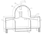
【課題】自動的に攪拌ユニットを洗浄でき、人力コストを削減し、リン酸ホルムアルデヒドなどの物が作業者に害を与えることを回避でき、作業効率を高めることができるリン酸尿素ホルムアルデヒド複合肥料の製造装置を提供する。【解決手段】本考案のリン酸尿素ホルムアルデヒド複合肥料の製造装置は貯水タンク1、貯薬タンク2、造粒ユニット3および反応タンク4を含み、前記反応タンク4には攪拌ユニットが設けられ、前記反応タンク4の上方には洗浄タンクが設けられ、前記洗浄タンクの底面が開放され、かつ前記反応タンク4と連通し、前記洗浄タンクには前記攪拌ユニットを洗浄するための洗浄ユニットが設けられ、前記反応タンク4の左右両側には貯蔵タンクが設けられ、前記貯蔵タンクは前記洗浄タンクと連通している。【選択図】図1[Problem] A phosphate urea formaldehyde compound fertilizer that can automatically clean the stirring unit, reduce labor costs, avoid substances such as phosphate formaldehyde from harming workers, and increase work efficiency. Provide manufacturing equipment. The apparatus for producing a phosphate urea formaldehyde composite fertilizer of the present invention includes a water storage tank 1, a drug storage tank 2, a granulation unit 3, and a reaction tank 4, the reaction tank 4 is provided with a stirring unit, and the A cleaning tank is provided above the reaction tank 4, the bottom surface of the cleaning tank is open and communicates with the reaction tank 4, and the cleaning tank is provided with a cleaning unit for cleaning the stirring unit, Storage tanks are provided on both left and right sides of the reaction tank 4, and the storage tanks communicate with the cleaning tank. [Selection diagram] Figure 1
Description
本考案は、化学肥料の製造技術分野に関し、特にリン酸尿素ホルムアルデヒド複合肥料の製造装置に関するものである。 TECHNICAL FIELD The present invention relates to the field of chemical fertilizer manufacturing technology, and more particularly to a manufacturing apparatus for phosphate-urea-formaldehyde compound fertilizer.
複合肥料とは2種類または2種類以上の栄養元素を含む化学肥料のことで、複合肥料は養分含有量が高く、副成分が少なく、物理的に性状がよいなどの利点があり、バランスよく施肥し、肥料の利用率を高め、作物の高収量安定生産を促進するために非常に重要な役割を果たしている。 Compound fertilizer is a chemical fertilizer that contains two or more nutrient elements. Compound fertilizer has the advantages of high nutrient content, few auxiliary ingredients, good physical properties, and balanced fertilization. It also plays a very important role in increasing the utilization rate of fertilizers and promoting high-yield and stable production of crops.
複合肥料によく見られる造粒技術では、ドラム造粒、ディスク造粒、スプレー造粒、タワー造粒などがあり、複合肥料の製造プロセスは原料配合、攪拌混合、造粒、篩分け、顆粒乾燥、顆粒冷却、顆粒被膜と完成品包装などを含み、攪拌混合過程において、多種の化学物質が使用され、化学物質の使用には危険性が存在しているため、作業員が近づかないようにする必要があり、また、攪拌時に化学物質が攪拌棒に付着し、洗浄されにくくなっている。 Common granulation techniques for compound fertilizers include drum granulation, disc granulation, spray granulation, tower granulation, etc. , granule cooling, granule coating and finished product packaging, etc. In the stirring and mixing process, various chemicals are used, and the use of chemicals is dangerous, so keep workers away In addition, chemical substances adhere to the stirring rod during stirring, making it difficult to wash.
そして、現在では、自動化され、かつ洗浄しやすいリン酸尿素ホルムアルデヒド複合肥料の製造装置が求められている。 At present, there is a demand for an automated, easy-to-clean apparatus for producing urea-phosphate-formaldehyde compound fertilizer.
本考案の解決課題は、自動的に攪拌ユニットを洗浄でき、人力コストを削減し、リン酸ホルムアルデヒドなどの物が作業者に害を与えることを回避でき、作業効率を高めることができるリン酸尿素ホルムアルデヒド複合肥料の製造装置を提供することにある。 The problem to be solved by the present invention is that the agitation unit can be cleaned automatically, the manpower cost can be reduced, the urea phosphate phosphate can be avoided from harming the workers such as formaldehyde phosphate, and the work efficiency can be improved. An object of the present invention is to provide an apparatus for producing formaldehyde compound fertilizer.
本考案が提供するリン酸尿素ホルムアルデヒド複合肥料の製造装置は貯水タンク、貯薬タンク造粒ユニットおよび反応タンクを備え、前記貯水タンク、貯薬タンクの排出端は前記反応タンクの入口端と連通し、前記反応タンクの出口端は前記造粒ユニットの入口端と連通し、前記反応タンクの貯薬タンクに近い側は前側であり、前記反応タンクの造粒ユニットに近い他方の側は後側であり、前記反応タンクには攪拌ユニットが設けられ、前記反応タンクの上方には洗浄タンクが設けられ、前記洗浄タンクの底面が開放されかつ前記反応タンクと連通し、前記洗浄タンクには前記攪拌ユニットを洗浄するための洗浄ユニットが設けられ、前記反応タンクの左右両側には貯蔵タンクが設けられ、当該貯蔵タンクは前記洗浄タンクと連通している。 The apparatus for producing phosphate-urea-formaldehyde compound fertilizer provided by the present invention comprises a water storage tank, a chemical storage tank granulation unit and a reaction tank, and the discharge ends of the water storage tank and the chemical storage tank communicate with the inlet end of the reaction tank. , the outlet end of the reaction tank communicates with the inlet end of the granulation unit, the side of the reaction tank closer to the reservoir tank is the front side, and the other side of the reaction tank closer to the granulation unit is the rear side; a stirring unit is provided in the reaction tank; a washing tank is provided above the reaction tank; the bottom surface of the washing tank is open and communicates with the reaction tank; A washing unit is provided for washing the reaction tank, and storage tanks are provided on both left and right sides of the reaction tank, and the storage tanks communicate with the washing tank.
好ましくは、前記攪拌ユニットは、前記反応タンクの前後側壁の間に回転可能に取り付けられた第1筒体を含み、当該第1筒体の軸線が地面と平行であり、前記第1筒体には第1モータが設けられ、当該第1モータの出力軸が前記第1筒体と同軸であり、且つ第1ベベルギアが固着され、前記反応タンクの外壁には第2モータが取り付けられ、当該第2モータの出力軸が前記反応タンクの側壁を貫通して前記第1筒体の一端の円心位置に固着され、前記第1筒体の円周外壁には軸線回りに2つの第1回転軸が均一に配列されており、前記第1回転軸はいずれもその軸線が前記第1筒体の軸線に垂直であり、その一端が回転可能に前記第1筒体内に挿入され、且つ第2ベベルギアが固着され、当該第2ベベルギアはいずれも前記第1ベベルギアに噛合し、前記第1回転軸の他端には攪拌ブレードが固着されている。 Preferably, the stirring unit includes a first cylinder rotatably mounted between the front and rear side walls of the reaction tank, the axis of the first cylinder being parallel to the ground, and the first cylinder having an axis parallel to the ground. is provided with a first motor, the output shaft of the first motor is coaxial with the first cylindrical body, the first bevel gear is fixed, the second motor is attached to the outer wall of the reaction tank, the second The output shafts of two motors pass through the side wall of the reaction tank and are fixed to the center position of one end of the first cylinder. are uniformly arranged, and each of the first rotating shafts has an axis perpendicular to the axis of the first cylindrical body, one end of which is rotatably inserted into the first cylindrical body, and a second bevel gear are fixed, the second bevel gears are both meshed with the first bevel gear, and a stirring blade is fixed to the other end of the first rotating shaft.
また、好ましくは、前記洗浄ユニットは、第1ディスクを含み、当該第1ディスクはその軸線が地面に垂直であり、前記洗浄タンクの前後内側壁には第1シュートが設けられ、当該第1シュートはその長手方向が地面に垂直であり、前記第1ディスクの両側がスライド可能に前記第1シュート内に位置し、前記第1ディスクの底面における非円心位置には複数の連結柱が固着され、当該連結柱はその他端が第2ディスクの上面に固着され、前記第1ディスクと前記第2ディスクは軸線が同じであり、前記第2ディスクには前記攪拌ブレードの翼数に対応する第2シュートが設けられ、前記第2シュートは前記第2ディスクの円心周りに均一に設けられ、且つその一端がいずれも円心を指向し、前記第1スライダはいずれも摺動可能に前記第2シュート内に位置し、前記第1スライダは前記第2ディスクの底面に位置する一端に取付ケースが固着され、当該取付ケースの底面には前記攪拌ブレードの両側を洗浄するための2つの洗浄ローラが回転可能に取付けられ、前記洗浄ローラはいずれも地面に垂直であり、前記取付ケース内に延びるその一端に第1ギアが固着され、2つの前記第1ギアは互いに噛合しており、前記取付ケース内には第3モータが設けられ、当該第3モータの出力軸は1つの前記第1ギアの円心位置に固着されており、前記第1ディスクの底面における円心位置には第4モータが固着され、当該第4モータの出力軸は前記第2ディスクを指向し、かつ揺動板の一端が固着され、前記第2ディスクの上面に位置する前記第1スライダの一端にはいずれも第1ヒンジロッドがヒンジ接続され、当該第1ヒンジロッドの他端はいずれも前記揺動板の他端にヒンジ接続され、前記第2ディスクの底面には、隣接する2つの前記攪拌ブレードのブレード間の隙間に挿入可能なガイド板が複数固着され、当該ガイド板の数は前記攪拌ブレードの隙間の数に対応し、当該ガイド板の前記第2ディスクから離れた一端にはガイド斜面が設けられ、当該ガイド板にはブラシが固着されている。 Further, preferably, the washing unit includes a first disk, the axis of the first disk is perpendicular to the ground, and the front and rear inner walls of the washing tank are provided with first chutes. has its longitudinal direction perpendicular to the ground, both sides of the first disc are slidably positioned in the first chute, and a plurality of connecting posts are fixed at non-circular positions on the bottom surface of the first disc. , the other end of the connecting column is fixed to the upper surface of the second disk, the first disk and the second disk have the same axis, and the second disk has a second disk corresponding to the number of blades of the stirring blades. A chute is provided, and the second chute is uniformly provided around the center of the second disk, and both ends thereof point toward the center of the circle. Positioned in a chute, the first slider has a mounting case fixed to one end located on the bottom surface of the second disk, and two cleaning rollers for cleaning both sides of the stirring blade on the bottom surface of the mounting case. The cleaning rollers are rotatably mounted, each of which is perpendicular to the ground, a first gear is fixed at one end thereof extending into the mounting case, the two first gears are meshed with each other, and the mounting case is A third motor is provided inside, the output shaft of the third motor is fixed to the center position of one of the first gears, and the fourth motor is located at the center position of the bottom surface of the first disk. The output shaft of the fourth motor is oriented toward the second disk, and one end of the oscillating plate is fixed to one end of the first slider located on the upper surface of the second disk. A hinge rod is hinge-connected, the other end of the first hinge rod is hinge-connected to the other end of the oscillating plate, and the bottom surface of the second disk is provided with a gap between the two adjacent stirring blades. A plurality of guide plates that can be inserted into the gaps are fixed, the number of the guide plates corresponds to the number of the gaps of the stirring blade, and one end of the guide plate away from the second disk is provided with a guide slope. A brush is fixed to the guide plate.
また、好ましくは、前記洗浄ユニットは、前記洗浄タンクの前後内側壁にそれぞれ設けられた第2ケースをさらに備え、2つの前記第2ケースの対向側が開放され、かつ前後方向に起伏する波シュートが設けられ、前記洗浄タンクの上面には2つの第1伸縮ロッドが取り付けられ、前記第1ディスクには2つの逃げ穴が設けられ、前記第1伸縮ロッドの伸縮端は前記逃げ穴を通って前記第2ケース内に入り込み、且ついずれも第1ケース本体が固着され、前記第1伸縮ロッドの前記逃げ穴を貫通するロッド部には第1ディスクを持ち上げることができるボスが固着され、前記洗浄ユニットは前記第1回転軸を挟持するための2つのC字状ブロックをさらに備え、当該C字状ブロック内の凹部側には複数のシャベル片が均一に固着され、各前記シャベル片は前記第1回転軸の円周外壁と鋭角を呈し、前記C字状ブロックの背部には第1連結ロッドが固着され、当該第1連結ロッドの他端は前記第2ケースの開放箇所から入り込み、前記第1ケース本体内に摺動可能に位置し、前記第1連結ロッドには、前記波状シュート内にスライド可能な第2スライダが設けられている。 Preferably, the washing unit further includes second cases provided on the front and rear inner walls of the washing tank, respectively, the opposing sides of the two second cases being open, and wave chutes undulating in the front-rear direction. Two first telescopic rods are installed on the upper surface of the washing tank, two escape holes are provided in the first disk, and telescopic ends of the first telescopic rods pass through the escape holes to the The cleaning unit enters into the second case and is fixed to the first case main body, and the rod part passing through the escape hole of the first telescopic rod is fixed to a boss capable of lifting the first disk. further includes two C-shaped blocks for sandwiching the first rotating shaft, and a plurality of shovel pieces are evenly fixed to the concave side in the C-shaped blocks, and each of the shovel pieces is attached to the first rotating shaft. A first connecting rod is fixed to the back of the C-shaped block, forming an acute angle with the outer circumferential wall of the rotating shaft. A second slider is slidably positioned within the case body, and the first connecting rod is provided with a second slider that is slidable within the wavy chute.
さらに、好ましくは、前記貯蔵タンクの前後内側壁の間には第3シュートが設けられ、当該第3シュートはその一端が前記貯蔵タンク内に位置し、その他端が前記反応タンク内に位置し、かつ前記第1筒体を指向し、前記第1筒体を指向する前記第3シュートの一端はその水平高さが他端よりも高く、前記第1筒体の円周外壁には複数のカードスロットが設けられ、当該カードスロットは前記第1筒体の軸心線と平行で、前記洗浄タンクと前記貯留タンクとを連通するためのろ過板は、前記第3シュート内に摺動可能に位置し、その一端が前記カードスロット内に入り込むことができ、前記ろ過板には洗浄タンクと反応タンクとを連通する複数のろ過孔が設けられ、前記ろ過板の底面にはラックが固着され、前記ラックは前記第3シュートの摺動方向と平行で、前記貯蔵タンクの外壁には第5モータが取り付けられ、前記第5モータの出力軸は前記貯蔵タンク内に入り込み、第3ギアが固着され、当該第3ギアは前記ラックと噛合し、前記第5モータの出力軸には第2ギアが固着され、当該第2ギアは前記貯蔵タンクの外に位置し、前記貯蔵タンクの前後内側壁の間には前記第3シュートの上方に位置し、前記第1筒体の軸心線と平行に配置された洗浄回転軸が設けられ、当該洗浄回転軸の一端は前記貯蔵タンクの側壁を通って前記貯蔵タンクの外へ突出し、第4ギアが固着されて、当該第4ギアは前記第2ギアと噛合している。 Further preferably, a third chute is provided between the front and rear inner walls of the storage tank, one end of the third chute is located in the storage tank and the other end is located in the reaction tank, One end of the third chute directed to the first cylinder is higher in horizontal height than the other end, and a plurality of cards are arranged on the outer circumferential wall of the first cylinder. A slot is provided, the card slot is parallel to the axis of the first cylindrical body, and a filter plate for communicating the washing tank and the storage tank is slidably positioned in the third chute. one end of which can be inserted into the card slot; the filter plate is provided with a plurality of filter holes communicating with the washing tank and the reaction tank; the bottom surface of the filter plate is fixed with a rack; The rack is parallel to the sliding direction of the third chute, a fifth motor is attached to the outer wall of the storage tank, the output shaft of the fifth motor enters the storage tank, and the third gear is fixed, The third gear meshes with the rack, the second gear is fixed to the output shaft of the fifth motor, the second gear is positioned outside the storage tank and between the front and rear inner walls of the storage tank. is located above the third chute and is provided with a cleaning rotary shaft arranged parallel to the axis of the first cylinder, and one end of the cleaning rotary shaft passes through the side wall of the storage tank and passes through the storage tank. Projecting out of the storage tank, a fourth gear is fixed, and the fourth gear meshes with the second gear.
さらに、好ましくは、前記貯水タンクは配管を介して前記洗浄タンクに連通し、前記貯薬タンクは配管を介して前記反応タンクに連通し、前記反応タンクの底面には加熱部材が設けられている。 Further preferably, the water storage tank communicates with the washing tank through a pipe, the chemical storage tank communicates with the reaction tank through a pipe, and a heating member is provided on the bottom surface of the reaction tank. .
本考案は自動的に攪拌ユニットを洗浄することができ、人力コストを削減し、リン酸ホルムアルデヒドなどの物が洗浄作業者に害を与えることを回避し、かつ攪拌レバーを洗浄する時に機械を止めずに分解することができ、作業効率を高めることができる。 The present invention can automatically clean the stirring unit, reduce manpower cost, avoid phosphate formaldehyde and other substances from harming the cleaning operator, and stop the machine when cleaning the stirring lever. It can be disassembled without any effort, and work efficiency can be improved.
また、洗浄ユニットは攪拌レバー部とブレードを別々に洗浄し、洗浄分業が明確で、洗浄効果がより良く、レバー部に付着物が堆積しやすく、レバー部を洗浄する時、攪拌ユニットは持続的に動作して停止せず、効率がより高く、攪拌ブレードを洗浄する水は繰り返し利用でき、コストを節約することができる。 In addition, the cleaning unit cleans the stirring lever part and the blade separately, the cleaning division of labor is clear, the cleaning effect is better, the lever part is easy to deposit, and the stirring unit can be used continuously when cleaning the lever part. It works continuously without stopping, the efficiency is higher, the water for cleaning the stirring blade can be reused repeatedly, and the cost can be saved.
本考案の他の利点、目的、および特徴はある程度、後述する明細書に記載され、あるいは、以下の考察に基づく研究は当業者にとって明らかであるか、または本考案の実践から教示され得る。本考案の目的及びその他の利点は、以下の明細書及び実用新案登録請求の範囲によって達成され得る。 Other advantages, objects, and features of the invention, to some extent, are set forth in the specification that follows, or will be apparent to those skilled in the art upon study based on the discussion that follows, or may be taught from practice of the invention. The objects and other advantages of the present invention may be achieved by the following specification and utility model claims.
以下、本考案を図面及び実施例を用いて詳しく説明する。 Hereinafter, the present invention will be described in detail with reference to drawings and examples.
本考案の実施形態の説明において、「中心」、「縦」、「横」、「上」、「下」、「前」、「後」、「左」、「右」、「垂直」、「水平」、「上」、「底」、「内」、「外」などの用語が示す方位または位置関係は、図面に示す方位または位置関係に基づくものであり、単に本考案の実施形態の説明を容易にし、説明を簡略化するために、指し示したり暗示したりするのではなく、指し示す装置や要素は特定の方位、特定の方位で構成され、動作されなければならないので、本考案の実施形態に対する制限とは理解できない。さらに、「第1」、「第2」、「第3」という用語は、説明の目的のためだけに使用され、相対的な重要性を示す、または暗示するとは理解されない。本考案の実施形態の説明において、特に明確な規定及び限定がない限り、用語「接続する」は広義に理解されるべきであり、例えば、固定接続であってもよいし、取り外し可能な接続であってもよいし、または一体接続であってもよい、機械的接続でもよいし、電気的接続でもよいし、直接接続でもよいし、中間媒体を介した間接的な接続でもよい。当業者であれば、本考案の実施形態における上記用語の具体的な意味を具体的に理解することができる。 In the description of the embodiments of the present invention, "center", "vertical", "horizontal", "top", "bottom", "front", "back", "left", "right", "vertical", " The orientations or positional relationships indicated by terms such as "horizontal", "top", "bottom", "inside", and "outside" are based on the orientations or positional relationships shown in the drawings and are merely descriptions of embodiments of the present invention. For ease of reference and simplicity of explanation, rather than pointing out or implying, the devices or elements pointed to must be configured and operated in a particular orientation, in a particular orientation, so that embodiments of the invention I don't understand the restrictions on Further, the terms "first," "second," and "third" are used for descriptive purposes only and are not understood to indicate or imply relative importance. In the description of the embodiments of the present invention, the term "connect" should be understood broadly, for example, it may be a fixed connection or a removable connection, unless otherwise clearly defined or limited. or integral connection, mechanical connection, electrical connection, direct connection, or indirect connection through an intermediate medium. A person skilled in the art can specifically understand the specific meaning of the above terms in the embodiments of the present invention.
図1~図4に示すように、本考案のリン酸尿素ホルムアルデヒド複合肥料の製造装置は、貯水タンク1、貯薬タンク2、造粒ユニット3を含み、前記製造装置は反応タンク4を含み、貯水タンク1、貯薬タンク2の排出端は反応タンク4の入口端と連通し、反応タンク4の出口端は造粒ユニット3の入口端と連通し、反応タンク4の貯薬タンク2に近い側は前側、造粒ユニット3に近い他方側は後側とされている。
As shown in FIGS. 1 to 4, the apparatus for producing phosphate-urea-formaldehyde compound fertilizer of the present invention includes a water storage tank 1, a chemical storage tank 2, and a granulation unit 3, the production apparatus includes a
前記反応タンク4内には攪拌ユニットが設置され、反応タンク4の上方には洗浄タンク5が設置され、洗浄タンク5の底面が開放され、かつ反応タンク4と連通し、洗浄タンク5内には攪拌ユニットを洗浄可能な洗浄ユニットが設置され、反応タンク4の左右両側には貯留タンク6が設置され、貯留タンク6は洗浄タンク5と連通している。
A stirring unit is installed in the
この実施例では、貯薬タンクに多種の薬剤が入っており、薬剤を反応タンクに入れて反応させ、反応後にスラリーを吸引して肥料造粒を行い、攪拌中にスラリーが攪拌ユニットに付着し、堆積物を形成する可能性があるため、常に洗浄する必要があり、洗浄ユニットは攪拌ユニットを洗浄し、洗浄された堆積物は貯蔵タンクに送られて貯蔵し、再び反応タンク内に落下しないようにする。 In this embodiment, various chemicals are stored in the chemical storage tank, and the chemicals are put into the reaction tank and reacted. After the reaction, the slurry is sucked to perform fertilizer granulation, and the slurry adheres to the stirring unit during stirring. , can form deposits, so it needs to be cleaned constantly, the cleaning unit cleans the stirring unit, and the cleaned deposits are sent to the storage tank for storage, and will not fall into the reaction tank again make it
本考案は自動的に攪拌ユニットを洗浄することができ、人力を減少させ、リン酸ホルムアルデヒドなどの物が洗浄作業員に害を与えることを回避し、かつ攪拌レバーを洗浄する時に機械を止めずに分解することができ、作業効率を高めることができる。 The present invention can automatically clean the stirring unit, reducing manpower, avoiding the harm caused by substances such as phosphate formaldehyde to the cleaning workers, and not stopping the machine when cleaning the stirring lever. It can be disassembled into parts, and work efficiency can be improved.
図5及び図6に示すように、攪拌ユニットは、反応タンク4の前後側壁の間に回転可能に取り付けられた第1筒体7を備え、当該第1筒体7の軸心線は地面と平行であり、第1筒体7内には第1モータ8が設けられ、第1モータ8の出力軸は第1筒体7と同軸であり、第1ベベルギア9が固着され、反応タンク4の外壁には第2モータ10が取り付けられ、第2モータ10の出力軸は、反応タンク4の側壁を介して第1筒体7の一端の円心位置に固着されている。
As shown in FIGS. 5 and 6, the stirring unit includes a first cylindrical body 7 rotatably attached between the front and rear side walls of the
前記第1筒体7の円周外壁には軸心線回りに2つの第1回転軸11が均一に配列されており、第1回転軸11の軸心線はいずれも第1筒体7の軸心線と垂直であり、一端が回転可能に第1筒体7内に入り込んで第2ベベルギア12が固着され、第2ベベルギア12はいずれも第1ベベルギア9と噛合し、第1回転軸11の他端には攪拌ブレード13が固着されている。
Two first rotating
この実施例では、第1モータは第1ベベルギアを回転駆動し、第1ベベルギアは2つの第2ベベルギアを回転駆動し、2つの第2ベベルギアは2つの第1回転軸を回転駆動し、第1回転軸は2つの攪拌ブレードを回転駆動し、1つの攪拌ブレードは反応タンク内で攪拌作業を行い、もう1つの攪拌ブレードは洗浄タンク内で洗浄を行い、2つの攪拌ブレードは同期回転し、第2モータは第1筒体を回転し、2つの攪拌ブレードの位置を切り替えることとなる。 In this embodiment, a first motor rotatably drives a first bevel gear, the first bevel gear rotatably drives two second bevel gears, two second bevel gears rotatably drive two first rotating shafts, and a first The rotating shaft drives two stirring blades to rotate, one stirring blade performs stirring work in the reaction tank, the other stirring blade performs cleaning in the washing tank, the two stirring blades rotate synchronously, and the second The two motors rotate the first cylinder and switch the positions of the two stirring blades.
図7~図10に示すように、前記洗浄ユニットは第1ディスク14を含み、当該第1ディスク14の軸心線が地面に垂直であり、前記洗浄タンク5の前後内側壁には第1シュート15が設けられ、当該第1シュート15の長手方向が地面に垂直であり、前記第1ディスク14の両側は前記第1シュート15内にスライド可能に位置し、前記第1ディスク14はその底面における非円心位置に複数の連結柱16が固着され、各連結柱16の他端は第2ディスク17の上面に固着されている。また、前記第1ディスク14は前記第2ディスク17と同軸心線であり、前記第2ディスク17には攪拌ブレード13の翼数に対応する第2シュート18が設けられ、前記第2シュート18は前記第2ディスク17の円心回りに均一に設けられ、一端はいずれも円心を指し、第1スライド19はいずれもスライド可能に前記第2シュート18内に位置し、前記第1スライド19は前記第2ディスク17の底面に位置する一端には取付ケース20が固着され、当該取付ケース20の底面には2つの攪拌ブレード13のブレード両側を洗浄するための洗浄ローラ21が回転可能に取り付けられている。当該洗浄ローラ21はともに地面に垂直であり、その一端が取付ケース20内に入り込んで第1ギア22が固着されている。また、2つの第1ギア22は互いに噛合している。前記取付ケース20内には第3モータ23が設けられ、第3モータ23の出力軸はその1つの第1ギア22の円心位置に固着されている。
As shown in FIGS. 7 to 10, the washing unit includes a
前記第1ディスク14の底面円心位置には第4モータ24が固着され、当該第4モータ24の出力軸は前記第2ディスク17を指向し、かつ揺動板25の一端に固着され、前記第2ディスク17の頂面に位置する前記第1スライダ19の一端にはともに第1ヒンジロッド26がヒンジ接続され、当該第1ヒンジロッド26の他端はともに前記揺動板25の他端にヒンジ接続されている。
A
前記第2ディスク17の底面には、隣接する2つの攪拌ブレード13のブレード間の隙間に挿入可能なガイド板27が複数固着されており、当該ガイド板27の数は攪拌ブレード13間の隙間の数に対応しており、前記ガイド板27の第2ディスク17から離れる一端にはガイド斜面28が設けられ、前記ガイド板27にはブラシ29が固着されている。
A plurality of guide plates 27 that can be inserted into the gap between two
この実施例では、前記攪拌ブレードはその棒部の回転速度がブレード部の回転速度より遅く、スラリーが付着されやすいため、頻繁に洗浄する必要がある。1つの攪拌ブレードが洗浄タンクまでに回転すると、第1ディスクは第1シュート内で下降し、第2ディスクの下降を牽引し、第2ディスク底面のガイド板は下に移動し、ガイド板は先端のガイド斜面によって攪拌ブレード間の隙間に挿入され、攪拌ブレードの回転を制限し、ブラシは攪拌ブレード軸部の位置を洗浄することができ、洗浄ローラは下降し、攪拌ブレードを中間に挟持し、第3モータは回転し、第1ギアの回転をもたらし、第1ギアは2つの洗浄ローラを逆回転させる。その際、力のバランスがよく、洗浄効果がより良くなる。 In this embodiment, the agitating blade needs to be washed frequently because the rotation speed of the rod portion is slower than that of the blade portion and the slurry easily adheres to the blade. When one stirring blade rotates to the cleaning tank, the first disk descends in the first chute, pulling the second disk downward, the guide plate on the bottom of the second disk moves downward, and the guide plate moves to the tip The brush is inserted into the gap between the stirring blades by the guide slope of , restricting the rotation of the stirring blades, the brush can wash the position of the stirring blade shaft, the cleaning roller descends, and the stirring blade is sandwiched in the middle, The third motor rotates, resulting in rotation of the first gear, which reverses the rotation of the two cleaning rollers. At that time, the force balance is good and the cleaning effect is better.
そして、第4モータは回転して、揺動板は回転して、揺動板は第1ヒンジロッドを動かして、第1ヒンジロッドは第1スライダを動かして、第1スライダは第2スライダ内でスライドして、取付ケースと洗浄ローラの往復運動をもたらして、攪拌ブレードを洗浄する。各第1ヒンジロッドはすべて揺動板にヒンジ接続されており、揺動板は複数の第1スライダを動かして順次規則的にスライドして、作業効率を向上し、隣接する2つの取付ケースの衝突も避けられる。 Then the fourth motor rotates, the wobble plate rotates, the wobble plate moves the first hinge rod, the first hinge rod moves the first slider, and the first slider moves inside the second slider. to provide reciprocating motion between the mounting case and the cleaning roller to clean the agitating blade. Each first hinge rod is hinge-connected to a swaying plate, and the swaying plate moves a plurality of first sliders to slide in sequence and regularity to improve work efficiency and prevent two adjacent mounting cases from Avoid collisions.
図7及び図10に示すように、前記洗浄ユニットは、前記洗浄タンク5の前後内側壁にそれぞれ設けられた2つの第2ケース30をさらに備え、2つの第2ケース30の対向側が開放され、前後方向に起伏する波状シュート31が設けられ、前記洗浄タンク5の上面には2つの第1伸縮ロッド32が取り付けられている。また、前記第1ディスク14には2つの逃げ穴33が設けられ、前記第1伸縮ロッド32の伸縮端は逃げ穴33を通って前記第2ケース30内に入り込んでおり、且つともに第1ケース本体34が固着され、前記逃げ穴33を貫通する前記第1伸縮ロッド32のロッド部には第1ディスク14を持ち上げることができるボス35が固着されている。
As shown in FIGS. 7 and 10, the cleaning unit further includes two
本実施形態の洗浄ユニットは、前記第1回転軸11を挟持可能な2つのC字状ブロック36をさらに含み、C字状ブロック36内の凹部側には複数のシャベル片37が均一に固着され、当該シャベル片37は第1回転軸11の円周外壁に対し鋭角を呈し、C字状ブロック36の背部には第1連結ロッド38が固着され、当該第1連結ロッド38の他端は前記第2ケース30の開放箇所から入り込み、前記第1ケース本体34内に摺動可能に位置し、前記第1リンク36には第2スライダ39が設けられ、当該第2スライダ39は、前記波状シュート31内に摺動可能に配置されている。
The cleaning unit of this embodiment further includes two C-shaped
この実施例では、第1伸縮ロッドが上昇すると、ボスは第1ディスクを持ち上げ、第1ディスクを第1シュート内で上昇させ、第2ディスク、取付ケースを上昇させ、洗浄ローラと攪拌ブレードを離脱させるようになる。 In this embodiment, when the first telescopic rod rises, the boss lifts the first disc, raises the first disc in the first chute, raises the second disc, the mounting case, and separates the cleaning roller and the stirring blade. will let you
第1伸縮ロッドが極限位置まで下降すると、洗浄ローラは攪拌ブレードと接触し、第1伸縮ロッドが下降する過程で、第1ボックス本体を下降させ、第1ボックス本体内の第1リンクは下降に追従し、第1リンク上の第2スライダは波浪シュート内でスライドし、第1リンクは第2スライダに牽引され、往復スライドを実現し、2つの第1リンクは往復スライドし、C字状ブロックの合体と分離を牽引し、上下運動と同時に合体と分離が行われ、ロッド部の上から下までの領域に対する洗浄が実現される。 When the first telescopic rod descends to the extreme position, the cleaning roller comes into contact with the agitating blade, and in the process of descending the first telescopic rod, the first box body is lowered, and the first link inside the first box body is lowered. follow, the second slider on the first link slides in the wave chute, the first link is pulled by the second slider, realizing reciprocating sliding, the two first links slide reciprocatingly, and the C-shaped block The combination and separation of the rods are pulled together, and the combination and separation are performed at the same time as the up-and-down movement, so that the cleaning of the area from the top to the bottom of the rod part is realized.
このとき、洗浄ローラは撹拌ブレードと接触せず、第1モータは回転し、撹拌ブレードを回転させ、C字状ブロックの内側のブレードは撹拌ロッドのロッド部を洗浄し、第1モータは正回転し、撹拌ロッドのロッド部の回転方向はブレードの向きと同じで、ブレードは撹拌ロッドのロッド部を洗浄し、第1モータは逆回転し、撹拌ロッド部の回転方向はブレードの向きと反対で、ブレードは撹拌ロッドのロッド部を洗浄し、洗浄強度はより大きくなる。 At this time, the cleaning roller does not contact the stirring blade, the first motor rotates, causing the stirring blade to rotate, the blade inside the C-shaped block cleans the rod part of the stirring rod, and the first motor rotates forward Then, the rotation direction of the rod part of the stirring rod is the same as the direction of the blade, the blade cleans the rod part of the stirring rod, the first motor rotates in the opposite direction, and the rotation direction of the stirring rod part is opposite to the direction of the blade. , the blade cleans the rod part of the stirring rod, and the cleaning intensity is greater.
第1伸縮ロッドが限界位置まで下降すると、ロッド部の洗浄が終了し、第1モータが停止し、洗浄ローラが攪拌ブレードに接触して洗浄を行うこととなる。 When the first extensible rod descends to the limit position, the washing of the rod portion ends, the first motor stops, and the washing roller comes into contact with the stirring blade to wash.
図3、図4、図11に示すように、前記貯留タンク6の前後内側壁の間には、一端が前記貯留タンク6内に位置し、他端が前記反応タンク4内に位置し、かつ前記第1筒体7に指向し、第3シュート40が前記第1筒体7の一端に指向する水平高さが他端よりも高く、前記第1筒体7の円周外壁には複数のカードスロット41が設けられ、当該カードスロット41は前記第1筒体7の軸心線と平行で、前記洗浄タンク5と前記貯留タンク6とを連通するためのろ過板42は、前記第3シュート40内に摺動可能に位置し、その一端が前記カードスロット41内に入り込むことができる。前記ろ過板42には、前記洗浄タンク5と前記反応タンク4とを連通する複数のろ過孔43が開設され、前記ろ過板42の底面には歯部44が固着され、当該歯部44は前記第3シュート40の摺動方向と平行で、前記貯留タンク6の外壁には第5モータ45が取り付けられ、当該第5モータ45の出力軸は前記貯蔵タンク6内に延び、第3ギア46が固着され、当該第3ギア46はラック44と噛合し、前記第5モータ45の出力軸には第2ギア47が固着され、当該第2ギア47は前記貯蔵タンク6の外に位置し、前記貯蔵タンク6の前後内側壁の間には洗浄回転軸48が回転可能に設けられ、当該洗浄回転軸48は前記第3シュート40の上方に位置し、前記第1筒体7の軸心線と平行であり、洗浄回転軸48の一端は、前記貯留タンク6の側壁を通って前記貯留タンク6の外へ突出し、第4ギア49が固着され、当該第4ギア49は前記第2ギア47に噛合している。
As shown in FIGS. 3, 4, and 11, between the front and rear inner walls of the storage tank 6, one end is positioned inside the storage tank 6, the other end is positioned inside the
この実施例では、ろ過板は洗浄タンクと反応タンクの間に位置し、洗浄タンクと貯蔵タンクを連通させ、洗浄タンク内が攪拌ブレードを洗浄すると、付着物がろ過板に従って貯蔵タンク内に落下し、水はろ過孔から反応タンクに流入し、洗浄後の水はスラリーの配合に用いられ、または反応タンクの洗浄に利用される。 In this embodiment, the filter plate is positioned between the washing tank and the reaction tank to allow communication between the washing tank and the storage tank. When the inside of the washing tank washes the agitating blade, the contaminants fall into the storage tank along the filter plate. , water flows into the reaction tank through the filtration holes, and the washed water is used for blending the slurry or used for washing the reaction tank.
攪拌ブレードを切り替える必要がある場合、第5モータは回転し、第3ギアを駆動し、第3ギアはラックを介してろ過板を駆動して貯蔵タンク内にスライドし、カードスロットを出て、第1筒体を緩めて、第1筒体は回転して、攪拌ブレードを切り替え、ろ過板はスライド中に、第2ギアは第4ギアを駆動し、第4ギアは洗浄回転軸を駆動し、ろ過板の表面を洗浄し、洗浄ローラの回転方向はろ過板のスライド方向と同じである。ろ過板に残った付着物スラグをタンク内へ洗浄される。 When the stirring blade needs to be switched, the fifth motor rotates and drives the third gear, which drives the filter plate through the rack to slide into the storage tank, exit the card slot, The first cylinder is loosened, the first cylinder rotates, the stirring blade is switched, the filter plate is sliding, the second gear drives the fourth gear, and the fourth gear drives the washing rotating shaft. , cleaning the surface of the filter plate, the rotating direction of the cleaning roller is the same as the sliding direction of the filter plate. Deposited slag remaining on the filter plate is washed into the tank.
図1~図3に示すように、前記貯水タンク1は配管を介して前記洗浄タンク5に連通し、前記貯薬タンク2は配管を介して前記反応タンク4に連通し、前記反応タンク4の底面には加熱部材50が設けられている。
As shown in FIGS. 1 to 3, the water storage tank 1 communicates with the washing tank 5 through a pipe, the chemical storage tank 2 communicates with the
この実施例では、貯薬タンクは直接反応タンクに投薬し、貯水タンクは水を洗浄タンクに送って洗浄し、水は再び反応タンクに流入してスラリーを配合するか反応タンクを洗浄するために利用され、反応タンク底面にスラリーを配合するための加熱ワイヤが設置されている。 In this embodiment, the medicament tank directly doses the reaction tank, the water tank sends water to the wash tank to wash, and the water flows back into the reaction tank to either formulate the slurry or wash the reaction tank. A heating wire is installed at the bottom of the reaction tank to blend the slurry.
なお、本考案のリン酸尿素ホルムアルデヒド複合肥料の製造装置を利用してリン酸尿素ホルムアルデヒド複合肥料を製造する際、以下の工程(ステップ)を含むようにしている。 In addition, when manufacturing a phosphate-urea-formaldehyde compound fertilizer using the apparatus for manufacturing a phosphate-urea-formaldehyde compound fertilizer of the present invention, the following processes (steps) are included.
S 1:60%~80%の濃度のリン酸6~10部を反応タンク4内に添加し、さらに10~30部の尿素を反応タンク4内に添加し、温度を60~90℃に制御し、攪拌速度を30~60r/minとし、十分に1h反応させる工程。
S 1: Add 6-10 parts of phosphoric acid with a concentration of 60%-80% into the
S 2:8~15部の濃度が20%~37%のホルムアルデヒドを反応タンク4に添加し、温度を60~90℃に制御し、20 min~3h反応して、リン酸尿素ホルムアルデヒドスラリーを得る工程。
S2: Add 8-15 parts of formaldehyde with a concentration of 20%-37% into the
S 3:リン酸尿素ホルムアルデヒドスラリーを造粒ユニット3に送り、リン酸尿素ホルムアルデヒド複合肥料製品を得る工程。 S3: Sending the urea phosphate-formaldehyde slurry to the granulation unit 3 to obtain a urea phosphate-formaldehyde compound fertilizer product.
この実施例では、6~10部(60%~80%)のリン酸を反応タンクに添加、10~30部の尿素を反応タンクに添加し、温度60~90℃に制御し、攪拌速度30~60 r/minとし、1h十分に反応させた後、8~15部の20%~37%のホルムアルデヒドを反応タンクに添加し、温度を60~90℃に制御し、20min~3h反応させ、リン酸尿素ホルムアルデヒドスラリーを得て、リン酸尿素ホルムアルデヒドスラリーをポンプで造粒ユニットに送り込み、50~80 kg/tの添加量と予め配合された一定配合比の窒素、リン、カリウム複合肥料を用いて造粒し、乾燥、篩分け、冷却を経てリン酸尿素ホルムアルデヒド徐放性複合肥料の完成品を得た。 In this example, 6-10 parts (60%-80%) phosphoric acid was added to the reaction tank, 10-30 parts urea was added to the reaction tank, the temperature was controlled at 60-90°C, and the stirring speed was 30. ~60 r/min, fully react for 1h, then add 8~15 parts of 20%~37% formaldehyde into the reaction tank, control the temperature at 60~90℃, react for 20min~3h, A urea phosphate formaldehyde slurry is obtained, and the urea phosphate formaldehyde slurry is pumped into the granulation unit, using an additive amount of 50-80 kg/t and a pre-blended nitrogen-phosphorus-potassium compound fertilizer with a certain mixing ratio. After granulation, drying, sieving, and cooling, a finished phosphate-urea-formaldehyde sustained-release compound fertilizer was obtained.
最後に説明すべきことは、上述の実施形態を参照して本考案を詳細に説明したが、本考案の趣旨と範囲のいかなる修正または均等置換から逸脱することなく、本考案の具体的な実施形態を修正または均等置換することができ、これらはすべて本考案の請求項の保護範囲内に含まれるべきである。 Finally, it should be noted that although the present invention has been described in detail with reference to the above-described embodiments, specific implementations of the invention may be made without departing from any modification or equivalent substitution within the spirit and scope of the invention. The forms may be modified or equivalently substituted, all of which should be included in the protection scope of the claims of the present invention.
1…貯水タンク、2…貯蔵タンク、3…造粒ユニット、4…反応タンク、5…洗浄タンク、6…貯蔵タンク、7…第1筒体、8…第1モータ、9…第1ベベルギア、10…第2モータ、11…第1回転軸、12…第2ベベルギア、13…攪拌ブレード、4…第1ディスク、15…第1シュート、16…連結柱、17…第2ディスク、18…第2シュート、19…第1スライダ、20…取付ケース、21…洗浄ローラ、22…第1ギア、23…第3モータ、24…第4モータ、25…揺動板、26…第1ヒンジロッド、27…ガイド板、28…ガイド斜面、29…ブラシ、30…第2ケース、31…波状シュート、32…第1伸縮ロッド、33…逃げ穴、34…第1ケース本体、35…ボス、36…C字状ブロック、37…シャベル片、38…第1連結ロッド、39…第2スライダ、40…第3シュート、41…カードスロット、42…ろ過板、43…ろ過孔、44…ラック、45…第5モータ、46…第3ギア、47…第2ギア、48…洗浄回転軸、49…第4ギア、50…加熱部材。
DESCRIPTION OF SYMBOLS 1... Water storage tank, 2... Storage tank, 3... Granulation unit, 4... Reaction tank, 5... Washing tank, 6... Storage tank, 7... First cylindrical body, 8... First motor, 9... First bevel gear, 10...Second motor, 11...First rotating shaft, 12...Second bevel gear, 13...Stirring blade, 4...First disc, 15...First chute, 16...Connecting column, 17...Second disc, 18...Second disc 2 chute, 19...first slider, 20...mounting case, 21...cleaning roller, 22...first gear, 23...third motor, 24...fourth motor, 25...swing plate, 26...first hinge rod, 27... Guide plate, 28... Guide slope, 29... Brush, 30... Second case, 31... Wavy chute, 32... First telescopic rod, 33... Escape hole, 34... First case body, 35... Boss, 36... C-shaped
Claims (6)
当該製造装置は反応タンク(4)を含み、前記貯水タンク(1)、貯薬タンク(2)の排出端は前記反応タンク(4)の入口端と連通し、前記反応タンク(4)の出口端は前記造粒ユニット(3)の入口端と連通し、前記反応タンク(4)の貯薬タンク(2)に近い側は前側であり、前記反応タンク(4)の造粒ユニット(3)に近い他方の側は後側であり、
前記反応タンク(4)には攪拌ユニットが設けられ、前記反応タンク(4)の上方には洗浄タンク(5)が設けられ、前記洗浄タンク(5)の底面が開放されかつ前記反応タンク(4)と連通し、前記洗浄タンク(5)には前記攪拌ユニットを洗浄するための洗浄ユニットが設けられ、前記反応タンク(4)の左右両側には貯蔵タンク(6)が設けられ、当該貯蔵タンク(6)は前記洗浄タンク(5)と連通していることを特徴とするリン酸尿素ホルムアルデヒド複合肥料の製造装置。 In a production equipment for phosphate-urea-formaldehyde compound fertilizer comprising a water storage tank (1), a chemical storage tank (2), and a granulation unit (3),
The manufacturing equipment comprises a reaction tank (4), the discharge ends of the water storage tank (1) and the chemical storage tank (2) communicate with the inlet end of the reaction tank (4), and the outlet of the reaction tank (4) The end communicates with the inlet end of the granulation unit (3), the side of the reaction tank (4) near the reservoir tank (2) is the front side, and the granulation unit (3) of the reaction tank (4) The other side closer to is the rear side, and
A stirring unit is provided in the reaction tank (4), a washing tank (5) is provided above the reaction tank (4), the bottom surface of the washing tank (5) is open and the reaction tank (4) is ), the washing tank (5) is provided with a washing unit for washing the stirring unit, and storage tanks (6) are provided on both left and right sides of the reaction tank (4). (6) is an apparatus for producing a phosphate-urea-formaldehyde compound fertilizer, characterized in that it communicates with the washing tank (5).
前記第1筒体(7)の円周外壁には軸線回りに2つの第1回転軸(11)が均一に配列されており、前記第1回転軸(11)はいずれもその軸線が前記第1筒体(7)の軸線に垂直であり、その一端が回転可能に前記第1筒体(7)内に挿入され、且つ第2ベベルギア(12)が固着され、当該第2ベベルギア(12)はいずれも前記第1ベベルギア(9)に噛合し、前記第1回転軸(11)の他端には攪拌ブレード(13)が固着されていることを特徴とする請求項1に記載のリン酸尿素ホルムアルデヒド複合肥料の製造装置。 The stirring unit includes a first cylindrical body (7) rotatably attached between the front and rear side walls of the reaction tank (4), the axis of the first cylindrical body (7) being parallel to the ground, The first cylindrical body (7) is provided with a first motor (8), the output shaft of the first motor (8) is coaxial with the first cylindrical body (7), and the first bevel gear (9 ) is fixed, and a second motor (10) is attached to the outer wall of the reaction tank (4). 1 It is fixed at the center position of one end of the cylindrical body (7),
Two first rotating shafts (11) are evenly arranged around the axis on the outer circumferential wall of the first cylindrical body (7). 1 perpendicular to the axis of the cylindrical body (7), one end thereof is rotatably inserted into the first cylindrical body (7), and a second bevel gear (12) is fixed, the second bevel gear (12) are both meshed with the first bevel gear (9), and a stirring blade (13) is fixed to the other end of the first rotating shaft (11). Manufacturing equipment for urea-formaldehyde compound fertilizer.
前記第1ディスク(14)の底面における円心位置には第4モータ(24)が固着され、当該第4モータ(24)の出力軸は前記第2ディスク(17)を指向し、かつ揺動板(25)の一端が固着され、前記第2ディスク(17)の上面に位置する前記第1スライダ(19)の一端にはいずれも第1ヒンジロッド(26)がヒンジ接続され、当該第1ヒンジロッド(26)の他端はいずれも前記揺動板(25)の他端にヒンジ接続され、
前記第2ディスク(17)の底面には、隣接する2つの前記攪拌ブレード(13)のブレード間の隙間に挿入可能なガイド板(27)が複数固着され、当該ガイド板(27)の数は前記攪拌ブレード(13)の隙間の数に対応し、当該ガイド板(27)の前記第2ディスク(17)から離れた一端にはガイド斜面(28)が設けられ、当該ガイド板(27)にはブラシ(29)が固着されていることを特徴とする請求項2に記載のリン酸尿素ホルムアルデヒド複合肥料の製造装置。 The washing unit includes a first disk (14), the first disk (14) has an axis perpendicular to the ground, and the front and rear inner walls of the washing tank (5) are provided with first chutes (15). wherein the first chute (15) has its longitudinal direction perpendicular to the ground, both sides of the first disc (14) are slidably positioned in the first chute (15), and A plurality of connecting posts (16) are fixed to non-circular positions on the bottom surface of (14), and the other ends of the connecting posts (16) are fixed to the upper surface of the second disk (17). 14) and the second disk (17) have the same axis, and the second disk (17) is provided with a second chute (18) corresponding to the number of blades of the stirring blade (13). The two chutes (18) are evenly provided around the center of the second disk (17), and one end thereof points toward the center of the circle, and both the first sliders (19) are slidable. Positioned in the second chute (18), the first slider (19) has one end positioned on the bottom surface of the second disc (17) and a mounting case (20) is fixed to the bottom surface of the mounting case (20). Two cleaning rollers (21) for cleaning both sides of the stirring blade (13) are rotatably mounted in the mounting case (20). A first gear (22) is fixed to one end extending inward, the two first gears (22) are meshed with each other, and a third motor (23) is provided in the mounting case (20). , the output shaft of the third motor (23) is fixed to the center position of one of the first gears (22),
A fourth motor (24) is fixed to the center position of the bottom surface of the first disk (14), and the output shaft of the fourth motor (24) points toward the second disk (17) and swings. One end of the plate (25) is fixed, and a first hinge rod (26) is hingedly connected to one end of the first slider (19) located on the upper surface of the second disk (17). The other end of the hinge rod (26) is hinged to the other end of the rocking plate (25),
A plurality of guide plates (27) that can be inserted into the gap between the two adjacent stirring blades (13) are fixed to the bottom surface of the second disk (17), and the number of the guide plates (27) is A guide slope (28) is provided at one end of the guide plate (27) away from the second disk (17) corresponding to the number of gaps in the stirring blade (13). The apparatus for producing phosphate-urea-formaldehyde compound fertilizer according to claim 2, characterized in that the brush (29) is fixed.
前記洗浄ユニットは前記第1回転軸(11)を挟持するための2つのC字状ブロック(36)をさらに備え、当該C字状ブロック(36)内の凹部側には複数のシャベル片(37)が均一に固着され、各前記シャベル片(37)は前記第1回転軸(11)の円周外壁と鋭角を呈し、前記C字状ブロック(36)の背部には第1連結ロッド(38)が固着され、当該第1連結ロッド(38)の他端は前記第2ケース(30)の開放箇所から入り込み、前記第1ケース本体(34)内に摺動可能に位置し、前記第1連結ロッド(38)には、前記波状シュート(31)内にスライド可能な第2スライダ(39)が設けられていることを特徴とする請求項3に記載のリン酸尿素ホルムアルデヒド複合肥料の製造装置。 The washing unit further includes second cases (30) provided on the front and rear inner walls of the washing tank (5), respectively. A wave chute (31) is provided, two first telescopic rods (32) are attached to the upper surface of the washing tank (5), and two escape holes (33) are provided in the first disk (14). provided, the telescopic end of the first telescopic rod (32) enters the second case (30) through the escape hole (33), and both are fixed to the first case body (34), A boss (35) capable of lifting the first disk (14) is fixed to the rod portion of the first telescopic rod (32) passing through the escape hole (33),
The cleaning unit further includes two C-shaped blocks (36) for sandwiching the first rotating shaft (11), and a plurality of shovel pieces (37 ) are fixed uniformly, each said shovel piece (37) presents an acute angle with the outer circumferential wall of said first rotating shaft (11), and a first connecting rod (38 ) is fixed, and the other end of the first connecting rod (38) enters from the open portion of the second case (30), is slidably positioned in the first case body (34), and the first connecting rod (38) 4. The apparatus for producing a phosphate-urea-formaldehyde compound fertilizer according to claim 3, wherein the connecting rod (38) is provided with a second slider (39) slidable in the wave-like chute (31). .
Priority Applications (1)
| Application Number | Priority Date | Filing Date | Title |
|---|---|---|---|
| JP2023002003U JP3243485U (en) | 2023-06-08 | 2023-06-08 | Manufacturing equipment for phosphate-urea-formaldehyde compound fertilizer |
Applications Claiming Priority (1)
| Application Number | Priority Date | Filing Date | Title |
|---|---|---|---|
| JP2023002003U JP3243485U (en) | 2023-06-08 | 2023-06-08 | Manufacturing equipment for phosphate-urea-formaldehyde compound fertilizer |
Publications (1)
| Publication Number | Publication Date |
|---|---|
| JP3243485U true JP3243485U (en) | 2023-08-30 |
Family
ID=87763041
Family Applications (1)
| Application Number | Title | Priority Date | Filing Date |
|---|---|---|---|
| JP2023002003U Active JP3243485U (en) | 2023-06-08 | 2023-06-08 | Manufacturing equipment for phosphate-urea-formaldehyde compound fertilizer |
Country Status (1)
| Country | Link |
|---|---|
| JP (1) | JP3243485U (en) |
Cited By (2)
| Publication number | Priority date | Publication date | Assignee | Title |
|---|---|---|---|---|
| CN117244510A (en) * | 2023-11-20 | 2023-12-19 | 内蒙古美力坚科技化工有限公司 | Amino C acid safe and efficient nitration treatment device |
| CN117359826A (en) * | 2023-12-08 | 2024-01-09 | 临沂康利医疗器械有限公司 | Cleaning equipment and cleaning method for producing isolation sound-transmitting film |
-
2023
- 2023-06-08 JP JP2023002003U patent/JP3243485U/en active Active
Cited By (3)
| Publication number | Priority date | Publication date | Assignee | Title |
|---|---|---|---|---|
| CN117244510A (en) * | 2023-11-20 | 2023-12-19 | 内蒙古美力坚科技化工有限公司 | Amino C acid safe and efficient nitration treatment device |
| CN117244510B (en) * | 2023-11-20 | 2024-01-12 | 内蒙古美力坚科技化工有限公司 | Amino C acid safe and efficient nitration treatment device |
| CN117359826A (en) * | 2023-12-08 | 2024-01-09 | 临沂康利医疗器械有限公司 | Cleaning equipment and cleaning method for producing isolation sound-transmitting film |
Similar Documents
| Publication | Publication Date | Title |
|---|---|---|
| JP3243485U (en) | Manufacturing equipment for phosphate-urea-formaldehyde compound fertilizer | |
| CN107318814A (en) | A kind of a wide range of pestsides synthesis flusher | |
| CN111034699A (en) | Adjustable plant protection machine for intercropping plants | |
| CN109005842A (en) | A kind of comprehensive watering fertilizing equipment of agricultural | |
| CN214516407U (en) | Shower bath production and processing is with chinese mugwort grass belt cleaning device of continuous feeding | |
| CN112352488A (en) | Distributed fertilizer injection unit that loosens soil is collected with soil to farming | |
| CN108849826A (en) | A kind of multi-functional irrigation rig of hydraulic engineering | |
| CN108246679A (en) | A kind of agricultural product washing slice device | |
| CN107094740A (en) | It is a kind of to prevent the vehicle-mounted sprayer of drug precipitation | |
| CN112119939B (en) | A poultry is bred and uses disinfectant sprinkler for indoor slide rail formula | |
| CN110574750B (en) | Farming is with swaing two-way sprinkler apparatus | |
| CN111700050A (en) | Agricultural that can adjust working range spouts medicine device | |
| CN114651805A (en) | Agricultural engineering self-cleaning mixes spraying apparatus | |
| CN216982582U (en) | Fruit tree is planted with spouting medicine device | |
| CN207591764U (en) | A kind of construction coating mixed stirring device | |
| CN213044186U (en) | Agricultural irrigation equipment with mixed fertilizer function | |
| CN211932211U (en) | Adjustable plant protection machine for intercropping plants | |
| CN212851718U (en) | Agricultural preparation seed is with mixing medicine device | |
| CN216601415U (en) | Pesticide sprinkler for afforestation | |
| CN210545973U (en) | Spare part coating spraying device for agricultural machine | |
| CN213908127U (en) | Pesticide spraying and mixing device for agricultural planting | |
| CN215775088U (en) | Special medicine device that spouts of municipal garden plant diseases and insect pests | |
| CN113952914B (en) | Production device and production method of urea sulfate formaldehyde compound fertilizer | |
| CN216567510U (en) | Mixed spraying equipment for agricultural planting | |
| CN212576208U (en) | Agricultural chemical fertilizer mixing arrangement convenient to wash |
Legal Events
| Date | Code | Title | Description |
|---|---|---|---|
| A521 | Request for written amendment filed |
Free format text: JAPANESE INTERMEDIATE CODE: A523 Effective date: 20230718 |
|
| R150 | Certificate of patent or registration of utility model |
Ref document number: 3243485 Country of ref document: JP Free format text: JAPANESE INTERMEDIATE CODE: R150 |