JP3215128U - Packaging bag - Google Patents
Packaging bag Download PDFInfo
- Publication number
- JP3215128U JP3215128U JP2017005658U JP2017005658U JP3215128U JP 3215128 U JP3215128 U JP 3215128U JP 2017005658 U JP2017005658 U JP 2017005658U JP 2017005658 U JP2017005658 U JP 2017005658U JP 3215128 U JP3215128 U JP 3215128U
- Authority
- JP
- Japan
- Prior art keywords
- packaging bag
- opening
- lid
- peripheral wall
- bent
- Prior art date
- Legal status (The legal status is an assumption and is not a legal conclusion. Google has not performed a legal analysis and makes no representation as to the accuracy of the status listed.)
- Active
Links
- 238000004806 packaging method and process Methods 0.000 title claims abstract description 58
- 230000002093 peripheral effect Effects 0.000 claims abstract description 71
- 238000005452 bending Methods 0.000 claims abstract description 37
- 238000000034 method Methods 0.000 abstract description 7
- 239000000463 material Substances 0.000 abstract description 4
- 229920003002 synthetic resin Polymers 0.000 description 16
- 239000000057 synthetic resin Substances 0.000 description 16
- 239000004745 nonwoven fabric Substances 0.000 description 8
- 235000013305 food Nutrition 0.000 description 5
- 230000035699 permeability Effects 0.000 description 4
- 230000000630 rising effect Effects 0.000 description 3
- 238000012546 transfer Methods 0.000 description 3
- 238000011161 development Methods 0.000 description 2
- 238000012986 modification Methods 0.000 description 2
- 230000004048 modification Effects 0.000 description 2
- 230000000149 penetrating effect Effects 0.000 description 2
- 238000007789 sealing Methods 0.000 description 2
- 238000003860 storage Methods 0.000 description 2
- 235000000832 Ayote Nutrition 0.000 description 1
- 235000009854 Cucurbita moschata Nutrition 0.000 description 1
- 240000001980 Cucurbita pepo Species 0.000 description 1
- 235000009804 Cucurbita pepo subsp pepo Nutrition 0.000 description 1
- 238000013461 design Methods 0.000 description 1
- 230000000694 effects Effects 0.000 description 1
- 239000003292 glue Substances 0.000 description 1
- 238000010030 laminating Methods 0.000 description 1
- 238000004519 manufacturing process Methods 0.000 description 1
- 235000015136 pumpkin Nutrition 0.000 description 1
- 238000003466 welding Methods 0.000 description 1
Images


Landscapes
- Bag Frames (AREA)
Abstract
【課題】作業工程及び材料費を削減させたうえで消費者の購買意欲を高めることができる包装用袋を提供する。【解決手段】包装用袋10は、一端に開口する開口部50を有し、他端に閉塞した底部30を有し、開口部から底部に向かって形成された周壁部20を備え、開口部から底部とは反対側に蓋部70が延設される。開口部を蓋部で覆うときに折り曲げ部分となる、蓋部と周壁部の境界部分及びその周辺部分で構成される折り曲げ予定部80に、始点部91と終点部92が配置される切り込みを有している。立体形状となった状態において、開口部が蓋部で覆われた状態になると、始点部と、終点部と、切り込みとで囲まれる領域が、折り曲げ予定部から上方に延びる表示部100を形成する。【選択図】図5The present invention provides a packaging bag that can increase consumers' willingness to purchase after reducing work processes and material costs. A packaging bag 10 has an opening 50 opened at one end, a bottom 30 closed at the other end, and a peripheral wall 20 formed from the opening toward the bottom. A lid 70 extends from the side opposite to the bottom. There is a notch in which the start point 91 and the end point 92 are arranged in the planned bending portion 80 constituted by the boundary portion of the lid portion and the peripheral wall portion and its peripheral portion, which becomes a bent portion when the opening portion is covered with the lid portion. is doing. When the opening is covered with the lid in the three-dimensional shape, a region surrounded by the start point, the end point, and the cut forms the display unit 100 that extends upward from the planned bending portion. . [Selection] Figure 5
Description
本考案は、食品等を店頭に陳列する際に使用する包装用袋に関する。 The present invention relates to a packaging bag used when displaying food or the like at a store.
食品等を店頭に陳列する際に使用する包装用袋として、本出願人が先にした特許文献1に記載されるものがある。これによれば、前壁部と、後壁部と、前壁部及び後壁部の下端に連接される底部と、前壁部及び後壁部の上端側に設けられる開口部と、前壁部から上方に向かって延設される蓋部と、を有していた。
As a packaging bag used when displaying food or the like at a store, there is one described in
包装用袋を折り畳んだ状態から、収納物を収納して自立可能な立体形状とし、収納物を開口部から収納して、蓋部で開口部を覆い、底部を下にして陳列台に陳列されるものであった。 From the folded state of the packaging bag, the stored items are stored in a self-supporting three-dimensional shape. The stored items are stored from the opening, covered with the lid, and displayed on the display stand with the bottom facing down. It was something.
これにより、食品の陳列のための食品の盛り付け、包装作業を一層容易化するとともに、食品の陳列用途に相応しい見映えのする包装用袋が得られていた。 As a result, a food packaging and packaging operation for displaying foods has been further facilitated, and a packaging bag suitable for food display applications has been obtained.
しかし、上記包装用袋では、陳列台に陳列した状態で消費者の購買意欲を高めたい場合には、周壁部を構成する前壁部にPOP広告を印刷したり、シール状に形成されたPOP広告を、前壁部の上端側に貼付したりすることが行われていた。 However, in the case of the above packaging bag, when it is desired to increase consumers' willingness to purchase in the state of being displayed on the display stand, a POP advertisement is printed on the front wall portion constituting the peripheral wall portion or a POP formed in a seal shape. It has been performed that an advertisement is pasted on the upper end side of the front wall portion.
前壁部にPOP広告を印刷する場合には、印刷が内部の収納物の視認性を低下させ、POP広告を貼付する場合には、包装用袋とは別にPOP広告のシールを購入して、そのシールを貼付する作業が必要となることになり、材料費及び作業工程の増加が生じるので、改善することが望まれていた。 When printing POP advertisements on the front wall, the printing reduces the visibility of the stored items inside. When attaching POP advertisements, purchase a POP advertisement seal separately from the packaging bag, Since the operation | work which sticks the seal | sticker will be needed and the increase in material cost and an operation process will arise, improvement was desired.
本考案は、上記事情に鑑み、作業工程及び材料費を削減させたうえで消費者の購買意欲を高めることができる包装用袋を提供することを目的とする。 In view of the above circumstances, an object of the present invention is to provide a packaging bag that can increase a consumer's willingness to purchase after reducing work processes and material costs.
請求項1記載の考案では、折り畳んだ状態において平坦となり、収納物を収納する状態において立体形状となり、自立可能に形成される包装用袋であって、
一端に開口する開口部を有し、他端に閉塞した底部を有し、前記開口部から前記底部に向かって形成された周壁部を備え、
前記開口部から前記底部とは反対側に蓋部が延設され、
前記開口部を前記蓋部で覆うときに折り曲げ部分となる、前記蓋部と前記周壁部の境界部分及びその周辺部分で構成される折り曲げ予定部に、始点部と終点部が配置される切り込みを有し、
立体形状となった状態において、前記開口部が前記蓋部で覆われた状態になると、前記始点部と、前記終点部と、前記切り込みとで囲まれる領域が、前記折り曲げ予定部から上方に延びる表示部を形成可能である。
The invention of
It has an opening that opens at one end, has a bottom that is closed at the other end, and includes a peripheral wall formed from the opening toward the bottom,
A lid extends from the opening to the opposite side of the bottom,
A notch in which a start point and an end point are arranged in a planned bending portion constituted by a boundary portion of the lid portion and the peripheral wall portion and its peripheral portion, which becomes a bent portion when the opening portion is covered with the lid portion. Have
When the opening is covered with the lid in the three-dimensional shape, a region surrounded by the start point, the end point, and the cut extends upward from the planned bending portion. A display portion can be formed.
これによれば、開口部を蓋部で覆う作業をすると、それに伴って折り曲げ予定部から上方に延びる表示部を形成できる。よって、包装用袋とは別にPOP広告のシールを購入して、そのシールを貼付する作業をなくすことが可能となるので、作業工程及び材料費を削減させたうえで消費者の購買意欲を高めることができる。また、表示部の部分に開放部分が生じるので、通気性を確保することが可能となる。表示部の部分に開放部分が生じることは、収納物の視認性を向上させることにもつながる。さらに、周壁部に施されていた印刷等の表示を表示部に移すことが可能となり、周壁部の表示面積を減少させることができるので、収納物の視認性を向上させることに寄与する。 According to this, when the operation of covering the opening with the lid is performed, it is possible to form a display portion that extends upward from the planned bending portion. Therefore, it is possible to purchase a POP advertising sticker separately from the packaging bag and eliminate the work of applying the sticker, thus increasing the consumer's willingness to purchase after reducing the work process and material costs. be able to. Moreover, since an open part arises in the part of a display part, it becomes possible to ensure air permeability. The generation of an open portion in the display portion also leads to improving the visibility of the stored items. Furthermore, it is possible to transfer the display such as printing applied to the peripheral wall portion to the display portion, and the display area of the peripheral wall portion can be reduced, which contributes to improving the visibility of the stored items.
また、前記折り曲げ予定部の幅方向に沿って前記始点部と、前記終点部を配置すれば、表示部の立ち上がり状態を、バランスよくすることができる。 In addition, if the start point and the end point are arranged along the width direction of the part to be bent, the rising state of the display unit can be balanced.
また、前記切り込みを、前記底部とは反対側に湾曲又は/及び屈曲して形成すれば、折り曲げ予定部を含んで蓋部側で表示部を形成する場合に好適なものとすることができる。 Further, if the notch is formed by being bent or / and bent on the side opposite to the bottom portion, it can be suitably used when the display portion is formed on the lid portion side including the portion to be bent.
また、前記切り込みを、前記底部側に湾曲又は/及び屈曲して形成すれば、折り曲げ予定部を含んで周壁部側で表示部を形成する場合に好適なものとすることができる。 In addition, if the cut is formed by bending or / and bending to the bottom side, it can be suitable when the display part is formed on the peripheral wall part side including the part to be bent.
また、前記始点部及び前記終点部を、外周縁部が角部分を有さない曲線で形成された孔で構成すれば、始点部及び終点部を、破損しやすい角部分を有さない形態として、始点部及び終点部を起点として、折り曲げ予定部が破損し、さらには蓋部、周壁部に破損が拡大することを防止することができる。 In addition, if the start point and the end point are configured by a hole formed by a curved line whose outer peripheral edge does not have a corner, the start point and the end are not in a form that does not have a corner that is easily damaged. Further, it is possible to prevent the planned bending portion from being damaged starting from the start point and the end point, and further to prevent the damage from expanding to the lid and the peripheral wall.
また、密封性を確保したうえで消費者の購買意欲を高めることを望むのであれば、前記開口部を閉塞可能とするファスナーを、前記開口部に配設することができる。 In addition, if it is desired to increase the consumer's willingness to purchase after securing the sealing performance, a fastener that can close the opening can be disposed in the opening.
本考案の包装用袋の第一の実施形態について図面に基づいて説明する。以下の説明において、各図面に記載される矢印の、前を前、後を後ろ、右を右、左を左、上を上、下を下、とする。 A first embodiment of a packaging bag of the present invention will be described based on the drawings. In the following description, the front and rear of arrows shown in the drawings are front, rear is right, right is left, left is left, top is top, and bottom is bottom.
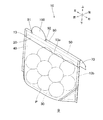
包装用袋10は、図3〜5に示すように、周壁部20と、周壁部20の下端に連接される底部30と、周壁部20の上端側に設けられる開口部50と、周壁部20から上方に向かって延設される蓋部70と、を有して袋状に形成された袋体13と、袋体13の外側に配設されるカバー部40と、底部30及び周壁部20の下端部の内側に配設される不織布60と、蓋部70と周壁部20の境界部分81及びその周辺部分82で構成される折り曲げ予定部80と、を有している。
As shown in FIGS. 3 to 5, the
図1〜2は、包装用袋10の内側と正対する展開図であり、図1においては、各部材の上下方向の位置を対応させてある。
1 and 2 are development views facing the inner side of the
包装用袋10は、図1、2に示す展開状態においては、袋体13を構成する合成樹脂フィルムF1と、カバー部40と、不織布60と、を有している。
The
袋体13は、無色透明で可撓性を有する略矩形状の合成樹脂フィルムF1で形成され、底部30と周壁部20との境界部分に谷折り線11a、11bが形成され、谷折り線11a、11bの間に山折り線12が形成されている。なお、本実施形態おいては、山折り、谷折りは、図4における山折り、谷折りをいう。山折り線12から谷折り線11aまでの長さと、山折り線12から谷折り線11bまでの長さとは略同一となるように形成されている。
The
底部30は、合成樹脂フィルムF1の谷折り線11a、11bで挟まれた矩形状の部分で構成されている。
The
周壁部20は、底部30の上下方向にそれぞれ連接する矩形状の部分で構成されている。
The
蓋部70は、下側の周壁部20から下方(折り畳んだ状態における上方)に延設され、左右の側端部の下側が切り取られた略台形状に形成されている。
The
折り曲げ予定部80は、蓋部70と周壁部20の境界部分81及びその周辺部分82で構成されている。折り曲げ予定部80は、図1、2、3であらわす網掛け線部分で示す部分となる。
The planned
折り曲げ予定部80を含む蓋部70には、底部30とは反対側に湾曲して形成された、切り込み90が配設されている。本実施形態では、切り込み90は、半円弧状に切り込まれている。
The
切り込み90の始点部91と、終点部92は、折り曲げ予定部80に配置され、さらに、折り曲げ予定部80の幅方向(左右方向)に沿って配置されている。
The
始点部91と、終点部92は、外周縁部が角部分を有さない曲線で形成された孔で構成されている。本実施形態では、円形に貫通された貫通孔で形成されている。
The
表示部100は、始点部91と、終点部92と、切り込み90とで囲まれる領域で構成され、蓋部70の後側(折り畳んだ状態における外側)の面に、既存の方法で製品名、品質表示等の印刷が施されている。表示部100は、開口部50が蓋部70で覆われた状態において、折り曲げ予定部80から上方に延びてPOP広告としての機能を発揮するものである。
The
カバー部40は、無色透明で可撓性を有する略矩形状の合成樹脂フィルムF2で形成され、周壁部20及び底部30と同幅の矩形状に形成され、周壁部20の一部を除いた領域及び底部30の全域を外側(図1、2における奥側)から覆い可能な面積を有している。
The
不織布60は、吸油性及び吸水性を有する部材で、周壁部20及び底部30と同幅の矩形状に形成され、底部30の全域及び周壁部20の底部30側の部分を内側(図1、2における手前側)から覆い可能な面積を有している。
The
包装用袋10の製造方法について説明する。
A method for manufacturing the
不織布60を、合成樹脂フィルムF1の底部30及び周壁部20の底部30側の部分の前側(折り畳んだ状態における内側)の面に重ね合わせ、左右の側端部60a、60bで、重ね合わせられる周壁部20及び底部30の左右の側端部20a、20b、30a、30bとそれぞれ接着し、図2の符号S1で示されるように、上側の周壁部20において、左右方向に沿って周壁部20と接着する。
The
なお、「接着」とは、熱溶着を含むものとする。 Note that “adhesion” includes heat welding.
次に、カバー部40を、周壁部20の一部を除いた領域及び底部30の全域を後側(折り畳んだ状態における外側)から覆うように重ね合わせ、左右の側端部40a、40bで、重ね合わせられる周壁部20及び底部30の左右の側端部20a、20b、30a、30bとそれぞれ接着する。
Next, the
さらに、図2の符号S2で示されるように、合成樹脂フィルムF1の、谷折り線11a、11bの左右の端部から若干離れた位置から、斜め方向に左右の側縁部まで帯状に四か所接着して、不織布60と合成樹脂フィルムF1とカバー部40とが接着される。
Furthermore, as shown by reference numeral S2 in FIG. 2, the synthetic resin film F1 is stripped from the position slightly separated from the left and right ends of the
上記の工程を経て、図2に示すような、三層に重ね合わされた状態の多層フィルム体F3が形成される。 Through the above-described steps, a multilayer film body F3 in a state of being superimposed on three layers as shown in FIG. 2 is formed.
そして、一枚の多層フィルム体F3の底部30を、底部30と重なり合うカバー部40及び不織布60とともに谷折り線11a、11b及び山折り線12に沿って、ガゼット形状に周壁部20の内側に折り曲げて重ね合わせ、多層フィルム体F3の左右の側端部を接着(シール)して、図3〜4に示すような、底部30と周壁部20と開口部50と有する袋状に形成された袋体13を有する包装用袋10が、完成する。
Then, the
完成した包装用袋10の袋体13の底部30以外の、前側となる部分が前側部13aとされ、後側となる部分が後側部13bとされている。
The part which becomes the front side other than the
周壁部20の左右の側端部20a、20bにおいて、不織布60と接着されていない部分は、周壁部20の前側部13aと後側部13bとが接着されている。
In the left and right
なお、本実施形態では、袋体13の、周壁部20と底部30と、開口部50と、蓋部70と、が特許請求の範囲の周壁部と、底部と、開口部と、蓋部と、に相当することになる。
In the present embodiment, the
包装用袋10を立体形状にして使用する態様及び機能について説明する。
The mode and function of using the
図3の包装用袋10を折り畳んだ状態から、折り曲げられている山折り線12部分を押し込んで底部30を広げるとともに、底部30の左右の側端部30a、30bを上側に折り曲げて、包装用袋10は、図5に示すように、収納物Pを収納して自立可能な立体形状となる、収納物Pを開口部50から収納して、蓋部70を下側に折り曲げ、後側の周壁部20にテープ等で止めて開口部50を閉じる。そして、底部30を下にして陳列台Bに陳列する。
From the state in which the
このとき、蓋部70は折り曲げられるが、始点部91と、終点部92と、切り込み90とで囲まれる領域で構成される表示部100は、蓋部70には追従せずに、周壁部20に略沿うような状態となる。換言すれば、折り曲げ予定部80から上方に延びる表示部100が形成され、人の目に留まりやすくなり、消費者の購買意欲を高めることになる。
At this time, the
また、表示部100の部分に開放部分が生じるので、通気性を確保することが可能となる。表示部100の部分に開放部分が生じることは、収納物Pの視認性を向上させることになる。さらに、周壁部20に施されていた印刷等の表示を表示部100に移すことが可能となり、周壁部20の表示面積を減少させることができるので、収納物Pの視認性を向上させる。
Moreover, since an open part arises in the part of the
また、折り曲げ予定部80の幅方向に沿って、始点部91と、終点部92が配置されているので、表示部100の立ち上がり状態を、バランスよくすることができる。
In addition, since the
これについて詳説すると、始点部91と、終点部92とを、幅方向(左右方向)に直交する方向(上下方向)にずれた位置に配置すると、蓋部70で開口部50を覆うときに、折り曲げ部分をまたがずに一方の側に始点部91と、終点部92が配置される場合には、表示部100が左右方向において非対称な形状となるが、上方に立ち上がるといえる。
More specifically, when the
しかし、蓋部70で開口部50を覆うときに、折り曲げ部分をまたいで始点部91と、終点部92を配置されてしまうと、蓋部70に追従して表示部100が、立ち上がりが足りずに後方に向かうが、上方に十分に立ち上がらない状態が発生しうるといえる。
However, when the
以上のことから、蓋部70で開口部50を覆うときに、蓋部70をどのように折り曲げるかによって左右されるが、折り曲げ予定部80の幅方向に沿って、始点部91と、終点部92が配置されていることが望ましいといえる。
From the above, when covering the
特に、人の目線より低い位置に包装用袋10を陳列した場合に、表示部100により、POP広告の効果が期待できる。
In particular, when the
また、始点部91と、終点部92を、角部分を有する多角形状の孔で形成してしまうと、角部分から折り曲げ予定部80を構成する合成樹脂フィルムF1が裂けて破損することが考えられる。
In addition, if the
よって、始点部91と、終点部92を、円形状の孔に形成し、蓋部70で開口部50を覆うときに、破損しやすい角部分を有さない形態とすることで、始点部91及び終点部92を起点として、折り曲げ予定部80が破損し、さらには蓋部70、周壁部20に破損が拡大することを防止することができる。
Therefore, when the
上記構成の包装用袋10では、折り畳んだ状態において平坦となり、収納物Pを収納する状態において立体形状となり、自立可能に形成される包装用袋であって、一端に開口する開口部50を有し、他端に閉塞した底部30を有し、開口部50から底部30に向かって形成された周壁部20を備え、開口部50から底部30とは反対側に蓋部70が延設され、開口部50を蓋部70で覆うときに折り曲げ部分となる、蓋部70と周壁部20の境界部分81及びその周辺部分82で構成される折り曲げ予定部80に、始点部91と終点部92が配置される切り込み90を有し、立体形状となった状態において、開口部50が蓋部70で覆われた状態になると、始点部91と、終点部92と、切り込み90とで囲まれる領域が、折り曲げ予定部80から上方に延びる表示部100を形成可能である。
The
これによれば、開口部50を蓋部70で覆う作業をすると、それに伴って折り曲げ予定部80から上方に延びる表示部100を形成できる。よって、包装用袋10とは別にPOP広告のシールを購入して、そのシールを貼付する作業をなくすことが可能となるので、作業工程及び材料費を削減させたうえで消費者の購買意欲を高めることができる。また、表示部100の部分に開放部分が生じるので、通気性を確保することが可能となる。表示部100の部分に開放部分が生じることは、収納物Pの視認性を向上させることにもつながる。さらに、周壁部20に施されていた印刷等の表示を表示部100に移すことが可能となり、周壁部20の表示面積を減少させることができるので、収納物Pの視認性を向上させることに寄与する。
According to this, when the operation of covering the
また、折り曲げ予定部80の幅方向に沿って始点部91と、終点部92を配置しているので、表示部100の立ち上がり状態を、バランスよくすることができる。
In addition, since the
また、切り込み90を、底部30とは反対側に湾曲して形成しているので、折り曲げ予定部80を含んで蓋部70側で表示部100を形成する場合に好適なものとすることができる。
In addition, since the
また、始点部91及び終点部92を、外周縁部が角部分を有さない曲線で形成された孔で構成しているので、始点部91及び終点部92を、破損しやすい角部分を有さない形態として、始点部91及び終点部92を起点として、折り曲げ予定部80が破損し、さらには蓋部70、周壁部20に破損が拡大することを防止することができる。
In addition, since the
本考案の第二の実施形態について説明する。 A second embodiment of the present invention will be described.
包装用袋210は、図6〜8に示すように、前壁部221と後壁部222とを備える周壁部220と、前壁部221及び後壁部222の下端に連接される底部230と、前壁部221及び後壁部222の上端側に設けられる開口部250と、前壁部221から上方に向かって延設される蓋部270と、を有している。
As shown in FIGS. 6 to 8, the
底部230と、後壁部222と、前壁部221の下側の一部は、略矩形状の紙Gから構成され、前壁部221の残りの部分と、蓋部270とは、1枚からなる略矩形状の合成樹脂フィルムF11から構成されている。
The bottom 230, the
紙Gは、底部230と前壁部221及び後壁部222との境界部分に谷折り線211a、211bが形成され、谷折り線211a、211bの間に山折り線212が形成されている。なお、山折り、谷折りは、包装用袋210の内側から見た状態をいう。
In the paper G,
底部230は、紙Gの谷折り線211a、211bで挟まれた矩形状の部分で構成されていることになる。
The
包装用袋210は、図6〜8に示すように、前壁部221を構成する合成樹脂フィルムF11の左右の上方端部F11a、F11bと、後壁部222を構成する紙Gの左右の上方端部Ga、Gbとが、それぞれ接着されている。
As shown in FIGS. 6 to 8, the
底部230を構成する紙Gの、谷折り線211bから山折り線212までの部分Ge、Gfは、紙Gが折り返されて、後壁部222を構成する紙Gの左右の下方端部Gc、Gdと、接着されている。
The portions Ge and Gf of the paper G constituting the
底部230の、谷折り線211aから山折り線212までの部分Gh、Giは、紙Gが折り返されて、谷折り線211a側の部分が、前壁部221を構成する紙Gの左右の側端部Gj、Gkと、接着されている。また、底部230の、谷折り線211aから山折り線212までの部分Gh、Giは、紙Gが折り返されて、山折り線212側の部分が、前壁部221を構成する合成樹脂フィルムF11の左右の下方端部F11c、F11dと、接着されている。
The portions Gh and Gi of the
折り曲げ予定部280は、蓋部270と周壁部220の境界部分281及びその周辺部分282で構成されている。折り曲げ予定部280は、図6であらわす網掛け線部分で示す部分となる。
The
折り曲げ予定部280を含む蓋部270には、底部230側に湾曲して形成された、切り込み290が配設されている。本実施形態では、切り込み290は、半円弧状に切り込まれている。
The
切り込み290の始点部291と、終点部292は、折り曲げ予定部280に配置され、さらに、折り曲げ予定部280の幅方向(左右方向)に沿って配置されている。
The
始点部291と、終点部292は、外周縁部が角部分を有さない曲線で形成された孔で構成されている。本実施形態では、円形に貫通された貫通孔で形成されている。
The
表示部300は、始点部291と、終点部292と、切り込み290とで囲まれる領域で構成され、前壁部221を構成する合成樹脂フィルムF11の後側(折り畳んだ状態における内側)の面に、既存の方法で製品名、品質表示等の印刷が施されている。
The
包装用袋210の使用態様を説明する。図6の包装用袋210を折り畳んだ状態から、折り曲げられている山折り線212部分を押し込んで底部230を広げて、包装用袋210は、収納物Pを収納して自立可能な立体形状となる。そして、収納物Pを開口部250から収納して、蓋部270を下側に折り曲げ、後側の後壁部222にテープ等で止めて開口部250を閉じて、底部230を下にして陳列台Bに陳列される。
The usage mode of the
このとき、図7に示すように、蓋部270は折り曲げられるが、始点部291と、終点部292と、切り込み290とで囲まれる領域で構成される表示部300は、前壁部221を構成する合成樹脂フィルムF11から立ち上がり、蓋部270に略沿うような状態となる。換言すれば、折り曲げ予定部280から上方に延びる表示部300が形成されることになる。
At this time, as shown in FIG. 7, the
このような構成とすれば、折り曲げ予定部280を含んで周壁部220側で表示部300を形成する場合に好適なものとすることができる。換言すれば、前壁部221に開放部分が生じるので、収納物Pの視認性を向上させることができる。
Such a configuration can be suitable for the case where the
第三の実施形態について説明する。包装用袋410は、図11(a)、(b)に示すように、周壁部420と、周壁部420の下端に連接される底部430と、周壁部420の上端側に設けられる開口部450と、周壁部420から上方に向かって延設される蓋部470と、を有して、一枚の合成樹脂フィルムF21を、谷折り線411a、411b、山折り線412で折り曲げて、底部430どうしが接着されないように、左右の側端部F21a、F21bを接着して、第二の実施形態の包装用袋210と同様の袋状に形成されている。
A third embodiment will be described. As shown in FIGS. 11A and 11B, the
開口部450の下側にファスナー510が、配設されている。ファスナー510は、合成樹脂製の咬合型ファスナーが用いられ、開口部450の幅と略同一の長さに形成され、開口部450における周壁部420の内面にそれぞれ接着されている。
A
包装用袋10と同様の、蓋部470と周壁部420の境界部分481及びその周辺部分482で構成される折り曲げ予定部480と、切り込み490と、始点部491と、終点部492と、表示部500と、を有している。
Similar to the
このような構成とすれば、通気性を考慮せずに、密封性を確保したうえで、消費者の購買意欲を高めたい場合に好適な包装用袋とすることができる。 With such a configuration, it is possible to provide a packaging bag suitable for increasing the consumer's willingness to purchase while ensuring airtightness without considering air permeability.
本考案の包装用袋10は上記構成に限定されるものではない。即ち、本発明の要旨を逸脱しない限り各種の設計変更等が可能である。
The
例えば、表示部100、300、500は、半円弧状に切り込み90、290、490を形成して、略半円形状としたが、図9(a)、(b)、(c)に示すように、矩形状、半六角形状、三角形状とすることができる。さらに、上記以外の多角形状、半オーバル形状等や、湾曲、屈曲した切り込みを組み合わせて形成することもできる。
For example, the
また、表示部100、300、500は、図9(d)に示す、サンタクロースの帽子のような形状、図9(e)に示す、雪だるまのような形状、図9(f)に示す、ハートのような形状、図9(g)に示す、ハロウィンのカボチャの提灯のような形状、など、使用時期、使用目的等に応じて適宜設定することも可能である。
The
また、始点部91、291、491、終点部92、292、492は、円形状の孔で形成したが、折り曲げ予定部80、280、480を破損させないのであれば、図10(a)、(b)に示すように、楕円、長孔等のオーバル形状を含む、外周縁部が角部分を有さない曲線で形成された孔で構成することができる。
Further, although the
なお、包装用袋全体を、一枚の紙Gから構成することも可能である。また、合成樹脂フィルム、不織布、紙を適宜組み合わせて構成することもでき、上記部材以外の他の部材を組み合わせることも可能である。 It is also possible to configure the entire packaging bag from a single sheet of paper G. Moreover, it can also comprise combining suitably a synthetic resin film, a nonwoven fabric, and paper, and it is also possible to combine other members other than the said member.
また、上記の実施形態では、底部に襠(マチ)が有る包装用袋(底ガゼット袋)に適用しているが、蓋部で開口部を覆い可能なものであれば、既存の他の包装用袋に適用することができる。例示すると、二方袋、三方袋、チャック付き三方袋、合掌袋(背張り)、ガゼット袋、スタンド袋、スタンドチャック袋、サイドシール袋、ボトムシール袋等が挙げられる。 Moreover, in said embodiment, although it applies to the packaging bag (bottom gusset bag) which has a gusset (gusset) in the bottom part, if it can cover an opening part with a cover part, other existing packaging Can be applied to bags. Illustrative examples include a two-sided bag, a three-sided bag, a three-sided bag with a chuck, a jointed bag (backing), a gusset bag, a stand bag, a stand chuck bag, a side seal bag, a bottom seal bag, and the like.
10 包装用袋
20 周壁部
30 底部
50 開口部
70 蓋部
80 折り曲げ予定部
81 境界部分
82 周辺部分
90 切り込み
91 始点部
92 終点部
100 表示部
210 包装用袋
220 周壁部
230 底部
250 開口部
270 蓋部
280 折り曲げ予定部
281 境界部分
282 周辺部分
290 切り込み
291 始点部
292 終点部
300 表示部
410 包装用袋
420 周壁部
430 底部
450 開口部
470 蓋部
480 折り曲げ予定部
481 境界部分
482 周辺部分
490 切り込み
491 始点部
492 終点部
500 表示部
510 ファスナー
P 収納物
DESCRIPTION OF
Claims (6)
一端に開口する開口部を有し、他端に閉塞した底部を有し、前記開口部から前記底部に向かって形成された周壁部を備え、
前記開口部から前記底部とは反対側に蓋部が延設され、
前記開口部を前記蓋部で覆うときに折り曲げ部分となる、前記蓋部と前記周壁部の境界部分及びその周辺部分で構成される折り曲げ予定部に、始点部と終点部が配置される切り込みを有し、
立体形状となった状態において、前記開口部が前記蓋部で覆われた状態になると、前記始点部と、前記終点部と、前記切り込みとで囲まれる領域が、前記折り曲げ予定部から上方に延びる表示部を形成可能であることを特徴とする包装用袋。 A packaging bag that is flat in the folded state, three-dimensionally shaped in a state of storing the stored items, and formed so as to be capable of self-supporting,
It has an opening that opens at one end, has a bottom that is closed at the other end, and includes a peripheral wall formed from the opening toward the bottom,
A lid extends from the opening to the opposite side of the bottom,
A notch in which a start point and an end point are arranged in a planned bending portion constituted by a boundary portion of the lid portion and the peripheral wall portion and its peripheral portion, which becomes a bent portion when the opening portion is covered with the lid portion. Have
When the opening is covered with the lid in the three-dimensional shape, a region surrounded by the start point, the end point, and the cut extends upward from the planned bending portion. A packaging bag characterized in that a display portion can be formed.
The packaging bag according to claim 3, wherein a fastener capable of closing the opening is disposed in the opening.
Priority Applications (1)
| Application Number | Priority Date | Filing Date | Title |
|---|---|---|---|
| JP2017005658U JP3215128U (en) | 2017-12-15 | 2017-12-15 | Packaging bag |
Applications Claiming Priority (1)
| Application Number | Priority Date | Filing Date | Title |
|---|---|---|---|
| JP2017005658U JP3215128U (en) | 2017-12-15 | 2017-12-15 | Packaging bag |
Publications (1)
| Publication Number | Publication Date |
|---|---|
| JP3215128U true JP3215128U (en) | 2018-03-01 |
Family
ID=61282815
Family Applications (1)
| Application Number | Title | Priority Date | Filing Date |
|---|---|---|---|
| JP2017005658U Active JP3215128U (en) | 2017-12-15 | 2017-12-15 | Packaging bag |
Country Status (1)
| Country | Link |
|---|---|
| JP (1) | JP3215128U (en) |
Cited By (1)
| Publication number | Priority date | Publication date | Assignee | Title |
|---|---|---|---|---|
| JP2022065906A (en) * | 2020-10-16 | 2022-04-28 | ソーシャル知財株式会社 | Manufacturing method of food bag and food bag |
-
2017
- 2017-12-15 JP JP2017005658U patent/JP3215128U/en active Active
Cited By (1)
| Publication number | Priority date | Publication date | Assignee | Title |
|---|---|---|---|---|
| JP2022065906A (en) * | 2020-10-16 | 2022-04-28 | ソーシャル知財株式会社 | Manufacturing method of food bag and food bag |
Similar Documents
| Publication | Publication Date | Title |
|---|---|---|
| JP6111237B2 (en) | container | |
| JP4764835B2 (en) | Method for making packaging bag for processed rice food and packaging bag for processed rice food | |
| JP3215128U (en) | Packaging bag | |
| JP2012153396A (en) | Packing package | |
| JP5722620B2 (en) | Sheet connection structure for packaging case and packaging case | |
| JP5927898B2 (en) | Product packaging method and package | |
| JP6218488B2 (en) | Packaging box with display function | |
| JP5022822B2 (en) | Packaged food for cooked rice processed food and packaged bag for processed cooked rice | |
| JP2018193114A (en) | Packing box | |
| JP2018100116A (en) | Self-standing packaging body | |
| JP6398229B2 (en) | Packaging tool and packaging tool | |
| JP5994247B2 (en) | Product packaging method and package | |
| JP3586276B2 (en) | envelope | |
| JP2019055783A (en) | Food packaging bag | |
| JP2018104069A (en) | Packaging body with mount | |
| JP5713356B2 (en) | Sealing set | |
| JP4899132B2 (en) | Small folding packaging box | |
| JP3189192U (en) | Packaging display box | |
| JP2020121724A (en) | Packaging material for rice ball | |
| JP6211997B2 (en) | Folding container | |
| JP6146221B2 (en) | Packaging box | |
| JP3232697U (en) | Exhibition panel | |
| JP2013163537A (en) | Packaging box | |
| JP2012086903A (en) | Cylindrical article holding case | |
| JP4456472B2 (en) | Continuous manufacturing method for packaging bags |
Legal Events
| Date | Code | Title | Description |
|---|---|---|---|
| R150 | Certificate of patent or registration of utility model |
Ref document number: 3215128 Country of ref document: JP Free format text: JAPANESE INTERMEDIATE CODE: R150 |
|
| R250 | Receipt of annual fees |
Free format text: JAPANESE INTERMEDIATE CODE: R250 |
|
| R250 | Receipt of annual fees |
Free format text: JAPANESE INTERMEDIATE CODE: R250 |