JP3189192U - Packaging display box - Google Patents
Packaging display box Download PDFInfo
- Publication number
- JP3189192U JP3189192U JP2013007136U JP2013007136U JP3189192U JP 3189192 U JP3189192 U JP 3189192U JP 2013007136 U JP2013007136 U JP 2013007136U JP 2013007136 U JP2013007136 U JP 2013007136U JP 3189192 U JP3189192 U JP 3189192U
- Authority
- JP
- Japan
- Prior art keywords
- plate
- top plate
- tray
- lid
- packaging
- Prior art date
- Legal status (The legal status is an assumption and is not a legal conclusion. Google has not performed a legal analysis and makes no representation as to the accuracy of the status listed.)
- Expired - Fee Related
Links
Images


Landscapes
- Cartons (AREA)
Abstract
【課題】商品の包装時に手作業で容易に組み立てられ、店頭では簡単に開封して商品を展示できる包装展示兼用箱を提供する。【解決手段】トレイ部分21が前受板1、側面板2、後面板3及び底板5,6から構成され、蓋部分22が天面板7及び前面板8並びにその両側にそれぞれ連設した天側板9及び前側板10から構成され、後面板3と天面板7とが繋がってトレイ部分21と蓋部分22とが結合され、蓋部分22では、天側板9と前側板10とが繋がり、天側板9に斜折線14が入れられたものとする。天側板9の斜折線14より後面板3側の部分を天面板7の内面に貼り付けて折畳状態とし、包装に際しては、天側板9を斜折線14沿いに折り返して組み立て、展示に際しては、天面板7の後部を手前に引き、後面板3と天面板7の境界の両端へ向かう切目線11aを切断し、トレイ部分21と蓋部分22とを分離する。【選択図】図5PROBLEM TO BE SOLVED: To provide a packaging display box which can be easily assembled by hand at the time of packaging a product and can be easily opened and displayed at a store. SOLUTION: A tray portion 21 is composed of a front receiving plate 1, a side plate 2, a rear surface plate 3 and a bottom plate 5, 6, and a lid portion 22 is a top plate 7 and a front plate 8 and a top plate connected to both sides thereof, respectively. 9 and the front side plate 10, the rear surface plate 3 and the top plate 7 are connected to connect the tray portion 21 and the lid portion 22, and in the lid portion 22, the top side plate 9 and the front side plate 10 are connected to each other, and the top side plate is connected. It is assumed that the diagonal fold line 14 is inserted in 9. The portion of the top plate 9 on the rear surface plate 3 side from the oblique fold line 14 is attached to the inner surface of the top plate 7 to be in a folded state. The rear portion of the top plate 7 is pulled toward the front, and the cut lines 11a toward both ends of the boundary between the rear surface plate 3 and the top plate 7 are cut to separate the tray portion 21 and the lid portion 22. [Selection diagram] Fig. 5
Description
この考案は、商品の包装及び展示に兼用される包装展示兼用箱に関するものである。 The present invention relates to a packaging display / combination box used for packaging and display of products.
従来、下記特許文献1には、図9に示すように、商品を収容するトレイ体51と、これに外側から被せる蓋体52とから成る包装展示兼用箱が記載されている。
Conventionally, as shown in FIG. 9,
この包装展示兼用箱のトレイ体51及び蓋体52は、別体のブランクからそれぞれ組み立てられ、トレイ体51は、底壁53、前面壁54、後面壁55及び一対の側面壁56を有し、蓋体52は、天面壁57、前面壁58、後面壁59及び一対の側面壁60を有するものとされている。前面壁54,58及び後面壁55には、それぞれミシン目状の切目線61a,62a,63aを入れて切取部61,62,63が設けられている。
The
そして、この包装展示兼用箱を使用して、商品を店舗への配送のため包装する際には、前面壁54,58を切取部61,62の領域内の接着部64で接着し、後面壁55,59を切取部63の領域内の接着部65で接着することにより、トレイ体51と蓋体52とを固定し、封緘状態とする。
Then, when packaging the product for delivery to the store using this packaging display combined box, the
一方、店頭で商品を展示する際には、切取部61,62を、切目線61a,62aの切断に伴い、貼り合わされた状態で前面壁54,58から切り取り、蓋体52を後面壁59の下端縁を中心にして回転させることにより、切取部63を、切目線63aの切断に伴い後面壁59に貼り付いた状態で、後面壁55から切り取る。
On the other hand, when displaying products at the store, the
このように開封すると、トレイ体51と蓋体52とが分離されるので、トレイ体51から蓋体52を除去して、トレイ体51に収容された商品を、買物客から見えやすいように露出させた状態で展示することができる。
Since the
なお、この包装展示兼用箱は、トレイ体51と蓋体52とを予め接着して折り畳んだ状態で、商品を包装する使用業者へ納品され、使用業者の出荷拠点で組み立てられる。
The packaging display combined box is delivered to a user who packs the product in a state where the
また、下記特許文献2には、トレイ体と蓋体とから成り、商品の包装時にトレイ体と蓋体とを接着固定し、商品の展示時にトレイ体と蓋体とを分離する2ピースの包装展示兼用箱において、ブランク状態で使用業者へ納品し、使用業者の出荷拠点に設置された包装機械でトレイ体と蓋体とを組み立てて接着固定するものが記載されている。
しかしながら、上記特許文献1に記載の包装展示兼用箱では、店頭で開封して展示状態とする際、切り取りに2段階の工程が必要となり、作業に手間取るという問題がある。
However, the packaging / exhibition box described in
また、上記特許文献2に記載の包装展示兼用箱では、使用業者側が包装機械を設置する際、多大なコストがかかるため、小ロットの商品の包装には適さないという問題がある。
Further, the packaging display / combination box described in
そこで、この考案は、商品の包装時に手作業で容易に組み立てられ、店頭では簡単に開封して商品を展示できる包装展示兼用箱を提供することを課題とする。 In view of this, an object of the present invention is to provide a packaging display box that can be easily assembled manually at the time of product packaging and can be easily opened and displayed at a store.
上記課題を解決するため、この考案に係る包装展示兼用箱は、商品を収納するトレイ部分と、これに被せる蓋部分とから成り、トレイ部分が前受板、側面板、後面板及び底板から構成され、蓋部分が天面板及び前面板並びにその両側にそれぞれ連設した天側板及び前側板から構成され、トレイ部分と蓋部分とは、後面板と天面板とが繋がって結合され、後面板と天面板の境界の両端へ向かう切目線が入れられ、蓋部分では、天側板と前側板とが繋がり、天側板の前側板寄りの部分に基端側の角部を起点とする斜折線が入れられたものとしたのである。 In order to solve the above problems, a packaging display combined box according to the present invention comprises a tray portion for storing products and a lid portion for covering the tray, and the tray portion is composed of a front receiving plate, a side plate, a rear plate and a bottom plate. The lid portion is composed of a top plate and a front plate, and a top plate and a front plate connected to both sides thereof, and the tray portion and the lid portion are joined together by connecting the rear plate and the top plate, and the rear plate and A score line is entered to both ends of the boundary of the top plate, and the lid and the top plate are connected to the front plate, and a diagonal line starting from the corner on the base end side is placed near the front plate of the top plate. It was assumed.
これにより、トレイ部分を偏平に折り畳むと共に、天面板及び前面板の内面に天側板及び前側板を折り重ね、天側板の斜折線より後面板側の部分を天面板に貼り付けて折畳状態としておくようにしたのである。 As a result, the tray portion is folded flat, the top plate and the front plate are folded on the inner surface of the top plate and the front plate, and the portion on the rear plate side from the oblique line of the top plate is attached to the top plate as a folded state. I tried to keep it.
そして、包装に際しては、トレイ部分を組み立てると共に、天側板を斜折線に沿って折り返すことにより蓋部分を組み立て、側面板の外面に前側板を重ねると共に、前受板の外面に前面板を重ねるようにしたのである。 When packaging, the tray part is assembled, the lid part is assembled by folding the top side plate along the oblique line, the front plate is overlaid on the outer surface of the side plate, and the front plate is overlaid on the outer surface of the front plate. It was.
また、展示に際しては、天面板の後部を手前に引いて、後面板と天面板の境界の両端へ向かう切目線を切断し、前面板を前受板から離反させることにより、トレイ部分と蓋部分とに分離するようにしたのである。 During the exhibition, pull the rear part of the top plate toward you, cut the cut line toward both ends of the boundary between the rear plate and the top plate, and move the front plate away from the front plate. They were separated.
この包装展示兼用箱は、トレイ部分を偏平に折り畳むと共に、天面板及び前面板の内面に天側板及び前側板を折り重ね、天側板の斜折線より後面板側の部分を天面板に貼り付けた折畳状態で使用業者に納品することにより、使用業者が商品を包装する際、手作業で容易に組み立てて蓋部分をトレイ部分に被せることができる。 In this packaging display box, the tray portion is folded flat, the top plate and the front plate are folded on the inner surface of the top plate and the front plate, and the rear plate side portion of the top plate is attached to the top plate. By delivering the product to the user in a folded state, when the user wraps the product, the user can easily assemble the product and put the lid portion on the tray portion.
そして、包装状態では、天面板に天側板の折返部分が重なるので、折り畳みに使用する斜折線が天面に位置し、側面に加工を施さないため強度劣化が少なく、耐圧強度に優れたものとなり、流通過程で多段に積み重ねても、変形しにくいものとなる。 In the packaged state, the folded portion of the top side plate overlaps the top plate, so the diagonal line used for folding is located on the top surface, and the side surface is not processed, so there is little deterioration in strength and excellent pressure resistance. Even when stacked in multiple stages in the distribution process, it becomes difficult to deform.
また、商品の展示に際しては、天面板の後部を手前に引き、後面板と天面板の境界の両端へ向かう切目線を切断することにより、簡単に開封することができるので、店頭での展示作業に伴う手間が軽減される。 In addition, when displaying products, the rear part of the top panel is pulled forward, and it can be easily opened by cutting the cut line toward both ends of the boundary between the rear panel and the top panel. The time and effort associated with is reduced.
そして、展示状態では、切断縁が目立たないので、美粧性に優れた展示ができ、トレイ部分の前受板により商品の前方へのこぼれ出しを防止すると共に、商品を後面板に凭れさせて展示することができる。 And in the display state, the cutting edge is inconspicuous, so it can be displayed with excellent cosmetics, the front plate of the tray part prevents the product from spilling forward, and the product is drowned on the back plate can do.
以下、この考案の実施形態を添付図面に基づいて説明する。 Embodiments of the present invention will be described below with reference to the accompanying drawings.
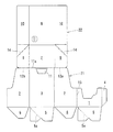
この包装展示兼用箱は、高さが奥行より大きい深型のものであり、図1に示す段ボールのブランクから組み立てられる。このブランクは、トレイ部分21と蓋部分22とから成り、段ボールの段目は、トレイ部分21と蓋部分22の連設方向へ向けられている。
This packaging display combined box is a deep type whose height is larger than the depth, and is assembled from a cardboard blank shown in FIG. The blank is composed of a
トレイ部分21は、前受板1の一側に側面板2、後面板3及び側面板2を順次連設し、前受板1の他側に継代片4を連設し、前受板1及び後面板3の下端に底板5を、側面板2の下端に底板6をそれぞれ連設した構成とされている。前受板1は、展示状態における商品の視認性を確保するため、高さが低く設定され、一対の側面板2は、後面板3へかけて高さが高くなっている。
The
蓋部分22は、天面板7の両側に天側板9を連設し、前面板8の両側に前側板10を連設した構成とされ、天側板9と前側板10とは、折目線を介して繋がっている。
The
トレイ部分21と蓋部分22とは、後面板3と天面板7とが繋がると共に、一対の側面板2と天側板9とが繋がって結合されている。
The
後面板3と天面板7の境界には、その中央部に後面板3内へ湾入するように、切目が断続するミシン目状の切目線を入れて押込部11が形成され、押込部11から両端へ向かってミシン目状の切目線11aが入れられている。
At the boundary between the
前受板1が隣接する側面板2と天側板9の境界には、折畳状態への組立時に容易に切断できるように、繋部の少ないミシン目状の切目線12aが入れられ、他方の側面板2と天側板9の境界には、使用業者に供給されるまで繋がった状態が保持されるように、繋部の多いミシン目状の切目線12bが入れられている。
The boundary between the
トレイ部分21において、前受板1と側面板2の境界には、折畳時の反発を軽減するため、押罫と切目とが交互に断続するリード罫の縦折線13が入れられ、底板5には、一側部分に基端側の角部を二等分する45°の斜折線5aが入れられている。斜折線5aは、谷折りが可能となるように、段ボールを表面側から押圧した押罫とされている。
In the
蓋部分22において、天側板9の前側板10寄りの部分には、基端側の角部を起点とする45°の斜折線14が入れられ、斜折線14は、谷折りが可能となるように、押罫と切目とが交互に断続するリード罫とされている。
In the
上記ブランクは、使用業者への供給に先立って、折畳状態とするため、図2に示すように、底板5を前受板1及び後面板3の内面に、底板6を側面板2の内面に、それぞれ重ねるように折り曲げ、底板5の一側部分を斜折線5aに沿って谷折りし、その折返部分を底板6に貼り付ける。
Since the blank is in a folded state prior to supply to the user, as shown in FIG. 2, the
次いで、図3に示すように、前受板1を、縦折線13に沿って隣接する一方の側面板2の内面に重ねるように折り曲げ、他方の側面板2を、後面板3の内面に重ねるように折り曲げて、継代片4を他方の側面板2の内面に貼り付け、この側面板2に繋がる天側板9及び前側板10もまた、それぞれ天面板7及び前面板8の内面に重なるように折り曲げる。
Next, as shown in FIG. 3, the
さらに、一方の天側板9を、切目線12aの切断に伴い側面板2から切り離し、この天側板9及びこれに繋がる前側板10を、それぞれ天面板7及び前面板8の内面に重ねるように一体として折り曲げる。天面板7から折り曲げられた両側の天側板9は、斜折線14より後面板3側の部分で天面板7の内面に貼り付ける。
Further, one
このような折畳状態とすると、嵩張らないので、使用業者への出荷拠点への輸送コストを抑制することができる。 Since it will not be bulky if it is such a folded state, the transportation cost to the shipping base to a user can be suppressed.
そして、使用業者において商品の包装のため組み立てる際には、図4に示すように、底板5の斜折線5aに沿った折り曲げを伸ばして、底板5,6が底壁を形成し、前受板1、一対の側面板2及び後面板3が四角筒状の周壁を形成するようにして、トレイ部分21を所定形状に立体化し、トレイ部分21に商品を収納する。
When the user assembles the product for packaging, as shown in FIG. 4, the folding along the
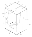
次に、天側板9を斜折線14に沿って折り返すことにより、天面板7から前面板8を直立させると共に、前面板8と前側板10とが直角をなすようにした状態で、後面板3から天面板7を起こすように折り曲げ、側面板2の外面に前側板10を重ねると共に、前受板1の外面に前面板8を重ねる。
Next, the
その後、図5に示すように、前面板8から底板5にかけて、封緘用のテープTを貼り付け、底板5,6から成る底壁を下底として直立させると、商品の出荷準備が完了する。
After that, as shown in FIG. 5, when the sealing tape T is applied from the
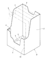
一方、店頭での商品の展示に際しては、後面上部の押込部11を押し込んで指を入れ、図6に示すように、天面板7の後部を手前に引くことにより、切目線11aを切断すると共に、蓋部分22を揺動させて開封し、テープTを剥がし又は切断して、前面板8を前受板1から離反させ、トレイ部分21と蓋部分22とに分離する。
On the other hand, when displaying the product at the storefront, the push-in
そして、トレイ部分21から蓋部分22を除去し、図7に示すように、トレイ部分21に収容された商品Gが露出した展示状態とする。この展示状態では、切断縁が目立たないので、美粧性に優れた展示ができ、前受板1により商品Gの前方へのこぼれ出しを防止すると共に、商品Gを後面板3に凭れさせて安定した状態で展示することができる。
And the
このように、上記包装展示兼用箱は、嵩張らない折畳状態で使用業者に納品することができ、使用業者が商品を包装する際には、包装機械を使用することなく、手作業で容易に組み立てて蓋部分22をトレイ部分21に被せることができる。
As described above, the packaging display box can be delivered to the user in a folded state that is not bulky, and when the user packs the product, it can be easily done manually without using a packaging machine. The
そして、包装状態では、天面板7に天側板9の折返部分が重なるので、折り畳みに使用する斜折線14が天面に位置し、側面に加工を施さないため強度劣化が少なく、耐圧強度に優れたものとなり、流通過程で多段に積み重ねても、変形しにくいものとなる。
In the packaged state, the folded portion of the
また、流通過程での輸送や保管に際しては、図8に示すように、隣り合う包装展示兼用箱を、前側板10が互い違いの向きとなるように並べると、包装展示兼用箱同士を隙間なく密着させて、収納効率を高めることができる。
In addition, when transporting and storing in the distribution process, as shown in FIG. 8, when the adjacent packaging display / combination boxes are arranged so that the
また、店頭での商品の展示に際しては、天面板7の後部を手前に引き、後面板3と天面板7の境界の両端へ向かう切目線11aを切断することにより、簡単に開封することができるので、店頭での展示作業に伴う手間が軽減される。
Further, when exhibiting products at the storefront, it can be easily opened by pulling the rear portion of the
なお、上記実施形態では、トレイ部分21の底壁がワンタッチ底型式のものを例示しているが、トレイ部分21の底壁は、タックエンド形式等、他の形式であってもよい。
In the above embodiment, the bottom wall of the
また、後面板3の両側に側面板2を連設し、一方の側面板2に前受板1を連設したものを例示しているが、後面板3の下端に底板5及び前受板1を順次連設して、後面板3から底板5を前方へ、底板5から前受板1を上方へ順次折り曲げ、後面板3から延びる側面板2に加えて、底板5及び前受板1の両側からも側面板2を延出し、これらの側面板2を重ねて貼り合わせるようにしてもよい。この場合、底板5から延びる側面板2に斜折線を入れて、偏平に折り曲げられるようにするとよい。
Further, the
また、後面板3に開封用の押込部11を設けたものを例示しているが、押込部11は、天面板7に設けてもよい。この場合、開封時に押込部11との干渉を避けるため、天側板9の後面板3側の部分を短くしておく必要がある。
Moreover, although what provided the
さらに、ブランクを折り曲げて折畳状態とする際、ホットメルト接着剤を使用して各部を接着するものを想定しているが、ホットメルト接着剤に換えて、他の接着剤や粘着テープを使用してもよい。 Furthermore, when the blank is folded into a folded state, it is assumed that each part is bonded using a hot melt adhesive, but other adhesives or adhesive tapes are used instead of the hot melt adhesive May be.
そのほか、材料として段ボールを使用したものを例示したが、段ボールに換えて、板紙等の他のシート材を材料として使用してもよい。 In addition, although what used corrugated cardboard as an example was illustrated, it replaced with corrugated cardboard and other sheet materials, such as paperboard, may be used as a material.
1 前受板
2 側面板
3 後面板
4 継代片
5,6 底板
5a 斜折線
7 天面板
8 前面板
9 天側板
10 前側板
11 押込部
11a 切目線
12a,12b 切目線
13 縦折線
14 斜折線
21 トレイ部分
22 蓋部分
G 商品
T テープ
DESCRIPTION OF
Claims (1)
トレイ部分(21)を偏平に折り畳むと共に、天面板(7)及び前面板(8)の内面に天側板(9)及び前側板(10)を折り重ね、天側板(9)の斜折線(14)より後面板(3)側の部分を天面板(7)に貼り付けて折畳状態とし、
包装に際しては、トレイ部分(21)を組み立てると共に、天側板(9)を斜折線(14)に沿って折り返すことにより蓋部分(22)を組み立て、側面板(2)の外面に前側板(10)を重ねると共に、前受板(1)の外面に前面板(8)を重ね、
展示に際しては、天面板(7)の後部を手前に引いて、後面板(3)と天面板(7)の境界の両端へ向かう切目線(11a)を切断し、前面板(8)を前受板(1)から離反させることにより、トレイ部分(21)と蓋部分(22)とに分離するようにした包装展示兼用箱。 It consists of a tray part (21) for storing products, and a lid part (22) that covers this, and the tray part (21) comprises a front receiving plate (1), a side plate (2), a rear plate (3) and a bottom plate ( 5 and 6), the lid portion (22) is composed of a top plate (7) and a front plate (8), and a top plate (9) and a front plate (10) connected to both sides thereof, and a tray portion. (21) and the lid portion (22), the back plate (3) and the top plate (7) are connected and joined, and a score line toward both ends of the boundary between the back plate (3) and the top plate (7) ( 11a), the lid (22) connects the top plate (9) and the front plate (10), and the base side corner is attached to the top plate (9) near the front plate (10). Assuming that the starting diagonal line (14) is entered,
The tray portion (21) is folded flat, and the top plate (9) and the front plate (10) are folded on the inner surfaces of the top plate (7) and the front plate (8), and the diagonal line (14 ) Paste the part on the rear panel (3) side to the top panel (7) to fold it,
When packaging, the tray portion (21) is assembled, the top side plate (9) is folded back along the oblique fold line (14) to assemble the lid portion (22), and the front side plate (10) is attached to the outer surface of the side plate (2). ) And the front plate (8) on the outer surface of the front plate (1)
During the exhibition, pull the rear part of the top panel (7) towards you, cut the cut line (11a) toward both ends of the boundary between the rear panel (3) and the top panel (7), and the front panel (8) A packaging display combined box which is separated from the tray (21) and the lid (22) by separating from the receiving plate (1).
Priority Applications (1)
| Application Number | Priority Date | Filing Date | Title |
|---|---|---|---|
| JP2013007136U JP3189192U (en) | 2013-12-17 | 2013-12-17 | Packaging display box |
Applications Claiming Priority (1)
| Application Number | Priority Date | Filing Date | Title |
|---|---|---|---|
| JP2013007136U JP3189192U (en) | 2013-12-17 | 2013-12-17 | Packaging display box |
Publications (1)
| Publication Number | Publication Date |
|---|---|
| JP3189192U true JP3189192U (en) | 2014-02-27 |
Family
ID=78225065
Family Applications (1)
| Application Number | Title | Priority Date | Filing Date |
|---|---|---|---|
| JP2013007136U Expired - Fee Related JP3189192U (en) | 2013-12-17 | 2013-12-17 | Packaging display box |
Country Status (1)
| Country | Link |
|---|---|
| JP (1) | JP3189192U (en) |
Cited By (1)
| Publication number | Priority date | Publication date | Assignee | Title |
|---|---|---|---|---|
| JP2016120967A (en) * | 2014-03-28 | 2016-07-07 | レンゴー株式会社 | Packaging and displaying box and packaging device |
-
2013
- 2013-12-17 JP JP2013007136U patent/JP3189192U/en not_active Expired - Fee Related
Cited By (1)
| Publication number | Priority date | Publication date | Assignee | Title |
|---|---|---|---|---|
| JP2016120967A (en) * | 2014-03-28 | 2016-07-07 | レンゴー株式会社 | Packaging and displaying box and packaging device |
Similar Documents
| Publication | Publication Date | Title |
|---|---|---|
| US20150344216A1 (en) | Folding cupcake box | |
| JP6452991B2 (en) | Packaging display box and its packaging equipment | |
| JP6503883B2 (en) | Packaging box | |
| WO2015060073A1 (en) | Box for packaging and exhibition, and packaging device for same | |
| US9938039B2 (en) | Box for packing and exhibiting product, and packing device therefor | |
| JP3242163U (en) | hanging display | |
| JP3189192U (en) | Packaging display box | |
| JP6183290B2 (en) | Packaging box with display function | |
| WO2021111799A1 (en) | Packaging box transformable into display stand | |
| JP3202167U (en) | Packaging display box | |
| JP2017019547A (en) | Two-piece packing box | |
| JP2016034842A (en) | Cutting-opening type packing box | |
| JP2008179371A (en) | Packaging box | |
| JP2016120967A (en) | Packaging and displaying box and packaging device | |
| JP5763969B2 (en) | 2-piece packaging box | |
| JP5657991B2 (en) | Packaging display box | |
| JP7217923B2 (en) | Pre-carton box and packaging box | |
| WO2016021553A1 (en) | Packaging box and packaging box blank sheet | |
| JP3183777U (en) | Cardboard box sheet for display and cardboard box for display | |
| JP6085280B2 (en) | Tray connector | |
| JP3174218U (en) | Shipping box | |
| JP3210387U (en) | Box sheet | |
| JP2014058339A (en) | Packaging box with exhibition function | |
| JP5537294B2 (en) | Packaging display box | |
| JP2015145274A (en) | Box for use both in packaging and in exhibition |
Legal Events
| Date | Code | Title | Description |
|---|---|---|---|
| R150 | Certificate of patent or registration of utility model |
Ref document number: 3189192 Country of ref document: JP Free format text: JAPANESE INTERMEDIATE CODE: R150 Free format text: JAPANESE INTERMEDIATE CODE: R150 |
|
| R250 | Receipt of annual fees |
Free format text: JAPANESE INTERMEDIATE CODE: R250 |
|
| R250 | Receipt of annual fees |
Free format text: JAPANESE INTERMEDIATE CODE: R250 |
|
| R250 | Receipt of annual fees |
Free format text: JAPANESE INTERMEDIATE CODE: R250 |
|
| R250 | Receipt of annual fees |
Free format text: JAPANESE INTERMEDIATE CODE: R250 |
|
| LAPS | Cancellation because of no payment of annual fees |