JP3205431U - Compressor cylinder exhaust structure of air compressor - Google Patents
Compressor cylinder exhaust structure of air compressor Download PDFInfo
- Publication number
- JP3205431U JP3205431U JP2016000643U JP2016000643U JP3205431U JP 3205431 U JP3205431 U JP 3205431U JP 2016000643 U JP2016000643 U JP 2016000643U JP 2016000643 U JP2016000643 U JP 2016000643U JP 3205431 U JP3205431 U JP 3205431U
- Authority
- JP
- Japan
- Prior art keywords
- exhaust
- compression cylinder
- valve body
- hole
- air
- Prior art date
- Legal status (The legal status is an assumption and is not a legal conclusion. Google has not performed a legal analysis and makes no representation as to the accuracy of the status listed.)
- Active
Links
Images


Classifications
-
- F—MECHANICAL ENGINEERING; LIGHTING; HEATING; WEAPONS; BLASTING
- F04—POSITIVE - DISPLACEMENT MACHINES FOR LIQUIDS; PUMPS FOR LIQUIDS OR ELASTIC FLUIDS
- F04B—POSITIVE-DISPLACEMENT MACHINES FOR LIQUIDS; PUMPS
- F04B39/00—Component parts, details, or accessories, of pumps or pumping systems specially adapted for elastic fluids, not otherwise provided for in, or of interest apart from, groups F04B25/00 - F04B37/00
- F04B39/12—Casings; Cylinders; Cylinder heads; Fluid connections
- F04B39/121—Casings
-
- F—MECHANICAL ENGINEERING; LIGHTING; HEATING; WEAPONS; BLASTING
- F04—POSITIVE - DISPLACEMENT MACHINES FOR LIQUIDS; PUMPS FOR LIQUIDS OR ELASTIC FLUIDS
- F04B—POSITIVE-DISPLACEMENT MACHINES FOR LIQUIDS; PUMPS
- F04B41/00—Pumping installations or systems specially adapted for elastic fluids
- F04B41/02—Pumping installations or systems specially adapted for elastic fluids having reservoirs
-
- F—MECHANICAL ENGINEERING; LIGHTING; HEATING; WEAPONS; BLASTING
- F04—POSITIVE - DISPLACEMENT MACHINES FOR LIQUIDS; PUMPS FOR LIQUIDS OR ELASTIC FLUIDS
- F04B—POSITIVE-DISPLACEMENT MACHINES FOR LIQUIDS; PUMPS
- F04B35/00—Piston pumps specially adapted for elastic fluids and characterised by the driving means to their working members, or by combination with, or adaptation to, specific driving engines or motors, not otherwise provided for
- F04B35/04—Piston pumps specially adapted for elastic fluids and characterised by the driving means to their working members, or by combination with, or adaptation to, specific driving engines or motors, not otherwise provided for the means being electric
-
- F—MECHANICAL ENGINEERING; LIGHTING; HEATING; WEAPONS; BLASTING
- F04—POSITIVE - DISPLACEMENT MACHINES FOR LIQUIDS; PUMPS FOR LIQUIDS OR ELASTIC FLUIDS
- F04B—POSITIVE-DISPLACEMENT MACHINES FOR LIQUIDS; PUMPS
- F04B39/00—Component parts, details, or accessories, of pumps or pumping systems specially adapted for elastic fluids, not otherwise provided for in, or of interest apart from, groups F04B25/00 - F04B37/00
- F04B39/0005—Component parts, details, or accessories, of pumps or pumping systems specially adapted for elastic fluids, not otherwise provided for in, or of interest apart from, groups F04B25/00 - F04B37/00 adaptations of pistons
-
- F—MECHANICAL ENGINEERING; LIGHTING; HEATING; WEAPONS; BLASTING
- F04—POSITIVE - DISPLACEMENT MACHINES FOR LIQUIDS; PUMPS FOR LIQUIDS OR ELASTIC FLUIDS
- F04B—POSITIVE-DISPLACEMENT MACHINES FOR LIQUIDS; PUMPS
- F04B39/00—Component parts, details, or accessories, of pumps or pumping systems specially adapted for elastic fluids, not otherwise provided for in, or of interest apart from, groups F04B25/00 - F04B37/00
- F04B39/10—Adaptations or arrangements of distribution members
-
- F—MECHANICAL ENGINEERING; LIGHTING; HEATING; WEAPONS; BLASTING
- F04—POSITIVE - DISPLACEMENT MACHINES FOR LIQUIDS; PUMPS FOR LIQUIDS OR ELASTIC FLUIDS
- F04B—POSITIVE-DISPLACEMENT MACHINES FOR LIQUIDS; PUMPS
- F04B39/00—Component parts, details, or accessories, of pumps or pumping systems specially adapted for elastic fluids, not otherwise provided for in, or of interest apart from, groups F04B25/00 - F04B37/00
- F04B39/12—Casings; Cylinders; Cylinder heads; Fluid connections
- F04B39/125—Cylinder heads
-
- F—MECHANICAL ENGINEERING; LIGHTING; HEATING; WEAPONS; BLASTING
- F04—POSITIVE - DISPLACEMENT MACHINES FOR LIQUIDS; PUMPS FOR LIQUIDS OR ELASTIC FLUIDS
- F04B—POSITIVE-DISPLACEMENT MACHINES FOR LIQUIDS; PUMPS
- F04B39/00—Component parts, details, or accessories, of pumps or pumping systems specially adapted for elastic fluids, not otherwise provided for in, or of interest apart from, groups F04B25/00 - F04B37/00
- F04B39/14—Provisions for readily assembling or disassembling
Abstract
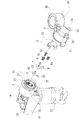
【課題】容易かつ速やかに気体注入速度を高めることができる、空気圧縮機の圧縮筒排気構造を提供する。【解決手段】空気圧縮機の圧縮筒排気構造は、メインフレーム11を含む。メインフレーム11には、モータ12が固定される。モータ12により歯車13が回転されると、圧縮筒2内に設けられたピストン本体14が歯車13により連動され、ピストン本体14が圧縮筒2内で往復運動して圧縮空気が発生し、空気貯蔵ユニット3の空気貯蔵チャンバ内に圧縮空気が進入する。圧縮筒2の頂壁には、複数の排気孔6が形成されている。複数の排気孔6は、孔径がそれぞれ異なる空気孔である。排気孔6には、それぞれ同じ構造を有するバルブ機構が配設されている。バルブ機構は、弁体8及びばね71により構成され、弁体8の底面面積は、排気孔6の孔径に等しい。【選択図】図2The present invention provides a compression cylinder exhaust structure of an air compressor capable of easily and quickly increasing a gas injection speed. A compression cylinder exhaust structure of an air compressor includes a main frame. A motor 12 is fixed to the main frame 11. When the gear 13 is rotated by the motor 12, the piston main body 14 provided in the compression cylinder 2 is interlocked by the gear 13, and the piston main body 14 reciprocates in the compression cylinder 2 to generate compressed air. Compressed air enters the air storage chamber of unit 3. A plurality of exhaust holes 6 are formed in the top wall of the compression cylinder 2. The plurality of exhaust holes 6 are air holes having different diameters. The exhaust holes 6 are provided with valve mechanisms having the same structure. The valve mechanism includes a valve body 8 and a spring 71, and the bottom surface area of the valve body 8 is equal to the diameter of the exhaust hole 6. [Selection] Figure 2
Description
本考案は、空気圧縮機の圧縮筒排気構造に関し、特に、圧縮筒が複数の孔径の異なる排気孔を有し、空気圧縮機の気体注入の開始から終了までの期間、圧縮筒内のピストン本体が往復圧縮運動を行う際、単位時間当たりの圧縮筒の空気貯蔵チャンバに進入する圧縮空気量が大幅に増える上、異なる孔径を有する排気孔の各弁体の背向圧がそれぞれ異なるため、圧縮された空気により背向圧が小さめの弁体を優先的かつ効果的に押動し、排気孔を介して空気貯蔵チャンバ内に進入し、ピストン本体の動作を円滑にして気体注入効率を高める、空気圧縮機の圧縮筒排気構造に関する。 The present invention relates to a compression cylinder exhaust structure of an air compressor, and in particular, the compression cylinder has a plurality of exhaust holes having different hole diameters, and a piston main body in the compression cylinder during a period from start to end of gas injection of the air compressor When reciprocating compression movement, the amount of compressed air entering the air storage chamber of the compression cylinder per unit time greatly increases, and the back pressure of each valve element of the exhaust hole having a different hole diameter is different. The valve body with a lower back pressure is preferentially and effectively pushed by the generated air, enters the air storage chamber through the exhaust hole, and smoothes the operation of the piston body to increase the gas injection efficiency. The present invention relates to a compression cylinder exhaust structure of an air compressor.
現段階で使用する空気圧縮機の構造は、基本的に圧縮筒を含む。圧縮筒内のピストン本体が往復運動すると圧縮空気が発生する。発生した圧縮空気が圧縮筒の排気孔を介してバルブ機構を押動し、圧縮空気を貯蔵するもう一つの空間に圧縮空気が進入する。この空間は、例えば、空気貯蔵ユニット(又は空気タンク)内の空間である。空気貯蔵ユニットには、圧縮空気を気体被注入物に送って気体注入する排気口が形成されている。従来の圧縮筒と空気貯蔵ユニットとの間の中間壁には、排気孔が1つのみ形成されている。排気孔の開閉はバルブ機構により制限される。バルブ機構は、弁体及びばねにより構成される。ピストン本体が発生させる圧縮空気は、弁体を押動してばねを圧縮し、圧縮空気が空気貯蔵ユニットの空気貯蔵チャンバに進入する。空気貯蔵チャンバに貯蔵される圧縮空気は、弁体に対して背向力を発生させ、気体注入段階で背向圧により弁体を押圧し、ピストン本体が動作する際に発生する圧縮空気により弁体を押動すると、抵抗力が高くなって円滑でなくなる。ピストン本体が動作するときには、さらに大きな抵抗力が発生するため、気体注入速度が下がり、空気圧縮機のモータが過熱してモータの運転効率が低下し、モータが焼損してしまう虞があった。そのため、従来の空気圧縮機の圧縮筒構造の欠点を改善する技術が求められていた。 The structure of the air compressor used at this stage basically includes a compression cylinder. When the piston body in the compression cylinder reciprocates, compressed air is generated. The generated compressed air pushes the valve mechanism through the exhaust hole of the compression cylinder, and the compressed air enters another space for storing the compressed air. This space is, for example, a space in the air storage unit (or air tank). The air storage unit is formed with an exhaust port through which compressed air is sent to the gas injection object and gas is injected. Only one exhaust hole is formed in the intermediate wall between the conventional compression cylinder and the air storage unit. The opening and closing of the exhaust hole is restricted by a valve mechanism. The valve mechanism includes a valve body and a spring. The compressed air generated by the piston body pushes the valve body to compress the spring, and the compressed air enters the air storage chamber of the air storage unit. The compressed air stored in the air storage chamber generates a backward force against the valve body, presses the valve body with the back pressure in the gas injection stage, and the compressed air generated when the piston body operates When you push your body, the resistance increases and it becomes unsmooth. When the piston main body is operated, a larger resistance force is generated, so that the gas injection speed is lowered, the motor of the air compressor is overheated, the motor operation efficiency is lowered, and the motor may be burned out. Therefore, there has been a demand for a technique for improving the drawbacks of the compression cylinder structure of the conventional air compressor.
本考案の主な目的は、圧縮筒が複数の孔径の異なる排気孔を有し、空気圧縮機の気体注入の開始から終了までの期間、圧縮筒内のピストン本体が往復圧縮運動を行う際、単位時間当たりの圧縮筒の空気貯蔵チャンバに進入する圧縮空気量が大幅に増える、空気圧縮機の圧縮筒排気構造を提供することにある。
本考案のもう一つの目的は、圧縮筒内のピストン本体が往復運動を行う圧縮筒が複数の孔径の異なる排気孔を有し、単位時間当たりの圧縮筒の空気貯蔵チャンバに進入する圧縮空気量が大幅に増える上、異なる孔径を有する排気孔の各弁体の背向圧がそれぞれ異なるため、圧縮された空気により背向圧が小さめの弁体を優先的かつ効果的に押動し、排気孔を介して空気貯蔵チャンバ内に進入し、ピストン本体の動作を円滑にして気体注入効率を高める上、背向圧が小さいためモータの負荷が減り、パワーが小さめのモータに代替することもでき、容易かつ速やかに気体注入速度を高めることができる、空気圧縮機の圧縮筒排気構造を提供することにある。
The main purpose of the present invention is that the compression cylinder has a plurality of exhaust holes with different hole diameters, and during the period from the start to the end of gas injection of the air compressor, the piston body in the compression cylinder performs a reciprocating compression motion. An object of the present invention is to provide a compressed cylinder exhaust structure for an air compressor, in which the amount of compressed air entering the air storage chamber of the compressed cylinder per unit time is greatly increased.
Another object of the present invention is that the compression cylinder in which the piston body in the compression cylinder reciprocates has a plurality of exhaust holes having different diameters, and the amount of compressed air entering the air storage chamber of the compression cylinder per unit time. In addition, since the back pressure of each valve body of exhaust holes having different hole diameters is different, the valve body with a smaller back pressure is preferentially and effectively pushed by the compressed air, It can enter the air storage chamber through the hole, smooth the operation of the piston body to increase the gas injection efficiency, reduce the back pressure and reduce the motor load, and can be replaced with a motor with lower power. An object of the present invention is to provide a compression cylinder exhaust structure for an air compressor that can easily and quickly increase the gas injection speed.
以下、本考案の実施形態について図に基づいて説明する。なお、これによって本考案が限定されるものではない。 Hereinafter, embodiments of the present invention will be described with reference to the drawings. Note that the present invention is not limited thereby.
図1を参照する。図1に示すように、本考案の一実施形態に係る空気圧縮機の圧縮筒排気構造は、メインフレーム11を含む。メインフレーム11には、モータ12が固定されている。モータ12が歯車13を回転させると、圧縮筒2内に設けられたピストン本体14が歯車13により連動される。ピストン本体14が圧縮筒2内で往復運動すると圧縮空気が発生し、圧縮空気が空気貯蔵ユニット3内に進入する。勿論、空気貯蔵ユニット3には、発生された圧縮空気が収容される。空気貯蔵ユニット3は、1つ又は複数の排気マニホールドを有する。例えば、マニホールド31は圧力計30に接続され、マニホールド33は、ガス抜き弁32に接続され、マニホールド34は、ホース(図示せず)を介して気体被注入物に接続される。
Please refer to FIG. As shown in FIG. 1, the compressed cylinder exhaust structure of an air compressor according to an embodiment of the present invention includes a
図2〜図7を参照する。図2〜図7に示すように、本考案の圧縮筒2の排気孔は、従来の設計と異なり、圧縮空気を出力する圧縮筒2の界面は、圧縮筒2の頂壁21でもよく、頂壁21には、複数の排気孔(本実施形態では排気孔4,5,6である)が形成されている。これら複数の排気孔4,5,6は、孔径が異なる空気孔でもよい(図3を参照する)。例えば、排気孔4の孔径X、排気孔5の孔径Y、排気孔6の孔径Zの関係は、X>Y>Zである。前述した排気孔4,5,6は、開いた状態又は閉じた状態であり、各排気孔が属するバルブ機構により制御される。各バルブ機構は、弁体及びばねにより構成される。各弁体の底面面積は、排気孔の孔径に等しい。例えば、大きい孔径を有する排気孔は、それに対応して弁体の底面面積も大きい。即ち、排気孔4に対応する弁体7の底面面積Aと、排気孔5に対応する弁体8の底面面積Bと、排気孔6に対応する弁体9の底面面積Cとの関係はA>B>Cである。前述した排気孔4,5,6は、弁体7,8,9によりそれぞれ封止される(図4を参照する)。ばね71,81,91は、弁体7,8,9上にそれぞれ着座される(図5を参照する)。係合部15は、圧縮筒2の頂端に設けられた環状ショルダ22上に係合され(図6を参照する)、係合部15上の弾性ピン16が環状ショルダ22に形成されたスナップ孔23に係合され、係合部15に設けた互いに離間した3本のコラム152,153,154を前述したばね71,81,91の他端に嵌挿し、3本のコラム152,153,154の末端を僅かな距離で離して前述した弁体7,8,9上に設け、弁体7,8,9が開閉動作を行う際の高さを制御して圧縮空気の吸気量を調整する。また、前述した弁体7,8,9がばね71,81,91の付勢力により排気孔4,5,6を完全に閉じると、空気貯蔵ユニット3は圧縮筒2と一体結合される。また、圧縮筒2の頂端周辺には、環状凸部24が設けられる。環状凸部24には、互いに対をなす2つの導入孔25が形成されている。空気貯蔵ユニット3は、嵌合クランプ35を有し、嵌合クランプ35をまず導入孔25に嵌挿させるが、結合動作の初期状態は図1に示す通りである。その後、空気貯蔵ユニット3を回転させると嵌合クランプ35が環状凸部24に係合され、空気貯蔵ユニット3が圧縮筒2上に位置決めされる(図10を参照する)。このように空気貯蔵ユニット3は、圧縮筒2に対して自由な角度で取り付け、図11に示すように、メーカーは設計の必要に応じて結合する角度を調整することができるため、実用的かつ便利である。
Please refer to FIG. As shown in FIGS. 2 to 7, the exhaust hole of the
図8及び図9を参照する。図8及び図9に示すように、ピストン本体14が圧縮筒2内で往復運動して発生する圧縮空気により、孔径がそれぞれ異なる排気孔4,5,6上の弁体7,8,9が押動されてばね71,81,91が圧縮し、圧縮空気が排気孔4,5,6を介して空気貯蔵ユニット3の空気貯蔵チャンバ36内に進入する。圧縮筒2のピストン本体14は、動作の開始から終了までの期間、初期の気体注入段階で発生する圧縮空気は、排気孔4,5,6を介して空気貯蔵チャンバ36内に速やかに進入し、単位時間当たりの圧縮筒の空気貯蔵ユニットに進入する圧縮空気量が増大する。中後期の気体注入段階に達すると、すでに有る大量の圧縮空気が空気貯蔵チャンバ36内に進入し、空気貯蔵チャンバ36内の圧縮空気が弁体7,8,9に対して反作用力を発生させるが、このことを本明細書では「背向圧」と表す。このような背向圧の現象は、弁体7,8,9の開放を抑制することができ、ピストン本体14が圧縮空気を押動する際に発生する抵抗力がより大きくなることを意味するが、本考案は異なる孔径を有する排気孔4,5,6と、それに対応した異なる孔径を有する弁体7,8,9とを組み合わせ、空気貯蔵チャンバ36内の背向圧により異なる底面面積の弁体7,8,9が受ける圧力が異なり、異なる孔径を有する排気孔の各弁体は背向圧も異なるため、圧縮された空気により背向圧が小さめの弁体を優先的かつ効果的に押動し、力を受ける小さめの面積の弁体9により圧縮筒2内に継続して発生する圧縮空気が空気貯蔵チャンバ36内に進入し、ピストン本体14の動作は、圧縮空気を送り込む際の抵抗力が小さいため、全体的にピストン本体14の動作が円滑かつ効率的となり、背向圧が減少してモータの負担が減るため、パワーが小さめのモータで代替してもよい。このように本考案の空気圧縮機の圧縮筒排気構造は、気体注入速度を容易かつ速やかに高めることができる。
Please refer to FIG. 8 and FIG. As shown in FIGS. 8 and 9, the
弁体7,8,9の昇降軌跡を安定させるために、排気孔4,5,6に位置する圧縮筒2の頂壁上には、画成リブ41,51,61が設けられ、弁体7,8,9は、画成リブ41,51,61により画成された軌跡内に位置する。これら画成リブ41,51,61の構造及び弁体7,8,9の状態は図2、図3、図4及び図5で表す。
In order to stabilize the up-and-down trajectory of the
図12を参照する。図12に示すように、本考案の他の実施形態に係る空気圧縮機の圧縮筒排気構造は、円径がそれぞれ異なるOリング42,52,62が排気孔4,5,6に嵌挿され、弁体7,8,9がOリング42,52,62上に配設される。ばね71,81,91の一端は、弁体7,8,9に当接され、ばね71,81,91の他端は係合部15に当接され、全体のバルブ機構が強固に位置決めされる。このような設計方式は、画成リブ41,51,61の構造を有さないが、Oリング42,52,62と、弁体7,8,9と、ばね71,81,91との組合せにより、気密効果を高めて圧縮空気が漏れることを防ぐことができる。
Please refer to FIG. As shown in FIG. 12, in the compression cylinder exhaust structure of an air compressor according to another embodiment of the present invention, O-
上述したことから分かるように、空気圧縮機の圧縮筒と空気貯蔵ユニットとの間の中間壁上に排気孔が1つだけ形成されていた従来技術と異なり、本考案の空気圧縮機の圧縮筒排気構造は、圧縮筒2の頂壁21にそれぞれ孔径が異なる複数の排気孔4,5,6と、それらに対応するように孔径が異なる弁体7,8,9とが組み合わされ、単位時間当たりの圧縮筒2の空気貯蔵チャンバ36の進入する圧縮空気量が増大する上、孔径が異なる排気孔4,5,6の各弁体7,8,9の背向圧が異なるため、圧縮空気により背向圧が小さめの弁体9を優先的かつ効果的に押動し、排気孔6を介して空気貯蔵チャンバ36内に進入し、ピストン本体14の動作が円滑となり、気体注入の効率が高まり、背向圧の減少によりモータの負荷も減るため、小さめのパワーを有するモータで代替することもできる。このように、本考案の空気圧縮機の圧縮筒排気構造は、気体注入速度を容易かつ速やかに高めるため、本考案は進歩性を備えて実用的である。
As can be seen from the above, unlike the prior art in which only one exhaust hole is formed on the intermediate wall between the compression cylinder of the air compressor and the air storage unit, the compression cylinder of the air compressor of the present invention In the exhaust structure, a plurality of
2 圧縮筒
3 空気貯蔵ユニット
4 排気孔
5 排気孔
6 排気孔
7 弁体
8 弁体
9 弁体
11 メインフレーム
12 モータ
13 歯車
14 ピストン本体
15 係合部
16 弾性ピン
21 頂壁
22 環状ショルダ
23 スナップ孔
24 環状凸部
25 導入孔
30 圧力計
31 マニホールド
32 ガス抜き弁
33 マニホールド
34 マニホールド
35 嵌合クランプ
36 空気貯蔵チャンバ
41 画成リブ
42 Oリング
51 画成リブ
52 Oリング
61 画成リブ
62 Oリング
71 ばね
81 ばね
91 ばね
152 コラム
153 コラム
154 コラム
2
Claims (5)
前記メインフレームには、モータが固定され、
前記モータにより歯車が回転されると、圧縮筒内に設けられたピストン本体が歯車により連動され、前記ピストン本体が前記圧縮筒内で往復運動して圧縮空気が発生し、空気貯蔵ユニットの空気貯蔵チャンバ内に圧縮空気が進入し、
前記圧縮筒の頂壁には、複数の排気孔が形成され、
前記複数の排気孔は、孔径がそれぞれ異なる空気孔であり、
前記排気孔の孔径はX>Y>Zであることを特徴とする空気圧縮機の圧縮筒排気構造。 A compression cylinder exhaust structure of an air compressor including a main frame,
A motor is fixed to the main frame,
When the gear is rotated by the motor, the piston main body provided in the compression cylinder is interlocked by the gear, the piston main body reciprocates in the compression cylinder to generate compressed air, and the air storage unit stores air. Compressed air enters the chamber,
A plurality of exhaust holes are formed in the top wall of the compression cylinder,
The plurality of exhaust holes are air holes having different hole diameters,
A compression cylinder exhaust structure of an air compressor, wherein a diameter of the exhaust hole is X>Y> Z.
前記バルブ機構は、弁体及びばねにより構成され、前記弁体の底面面積は、前記排気孔の孔径に等しく、
前記排気孔は、前記弁体によりそれぞれ封止され、
前記弁体の底面面積は、前記排気孔の孔径の大きさに等しく、前記排気孔の孔径が大きい場合、前記弁体の底面面積も大きくなり、
孔径Xの排気孔に対応する前記弁体の底面面積Aと、孔径Yの排気孔に対応する前記弁体の底面面積Bと、孔径Zの排気孔に対応する前記弁体の底面面積Cとの関係はA>B>Cであることを特徴とする請求項1に記載の空気圧縮機の圧縮筒排気構造。 The exhaust holes are provided with valve mechanisms having the same structure,
The valve mechanism is configured by a valve body and a spring, and the bottom surface area of the valve body is equal to the diameter of the exhaust hole,
The exhaust holes are respectively sealed by the valve body,
The bottom surface area of the valve body is equal to the size of the hole diameter of the exhaust hole, and when the hole diameter of the exhaust hole is large, the bottom surface area of the valve body also increases.
The bottom surface area A of the valve body corresponding to the exhaust hole having the hole diameter X, the bottom surface area B of the valve body corresponding to the exhaust hole having the hole diameter Y, and the bottom surface area C of the valve body corresponding to the exhaust hole having the hole diameter Z 2. The compressed cylinder exhaust structure of an air compressor according to claim 1, wherein A>B> C.
前記環状ショルダには、互いに対をなす2つのスナップ孔が形成され、
ばねの一端は、弁体に嵌挿され、
前記環状ショルダの前記スナップ孔には、係合部上の弾性ピンが係合され、
前記係合部に互いに間隔をあけて設けられた3本のコラムが前記ばねの他端に嵌挿され、前記3本のコラムの末端は、僅かに離れるように前記弁体上に位置し、前記弁体が行う開閉動作の上昇高さを制限して圧縮空気の吸気量を制御し、前記弁体が前記ばねの付勢力により前記排気孔が完全に閉じられ、
前記圧縮筒の頂壁には、前記排気孔に対応するように画成リブが設けられ、
前記弁体は、前記画成リブにより画成された軌跡内に位置することを特徴とする請求項2に記載の空気圧縮機の圧縮筒排気構造。 An annular shoulder is provided at the top end of the compression cylinder,
The annular shoulder is formed with two paired snap holes,
One end of the spring is inserted into the valve body,
An elastic pin on the engaging portion is engaged with the snap hole of the annular shoulder,
Three columns spaced apart from each other in the engagement portion are inserted into the other end of the spring, and the ends of the three columns are positioned on the valve body so as to be slightly separated from each other, Controlling the intake amount of compressed air by limiting the rising height of the opening and closing operation performed by the valve body, the exhaust hole is completely closed by the urging force of the valve body,
On the top wall of the compression cylinder, an defining rib is provided so as to correspond to the exhaust hole,
The compressed cylinder exhaust structure of an air compressor according to claim 2, wherein the valve body is located in a locus defined by the defining rib.
前記環状凸部には、互いに対をなす2つの導入孔が形成され、
前記空気貯蔵ユニットは、前記導入孔に嵌挿させる嵌合クランプを有するとともに、自在に回転して位置決め角度を決定し、前記空気貯蔵ユニットと前記圧縮筒とが結合されて一体成形されることを特徴とする請求項1に記載の空気圧縮機の圧縮筒排気構造。 Around the top end of the compression cylinder, an annular protrusion is provided,
The annular convex part is formed with two introduction holes that make a pair with each other,
The air storage unit has a fitting clamp to be fitted into the introduction hole, and freely rotates to determine a positioning angle, and the air storage unit and the compression cylinder are combined and integrally molded. The compression cylinder exhaust structure of the air compressor according to claim 1, characterized in that:
前記バルブ機構は、弁体、Oリング、ばねを含み、
前記Oリングは、前記排気孔上に配設され、
前記弁体は、前記Oリング上に配設され、
前記ばねは、前記弁体に当接され、
前記弁体により前記排気孔がそれぞれ封止されることを特徴とする請求項1に記載の空気圧縮機の圧縮筒排気構造。 A valve mechanism is disposed in the plurality of exhaust holes,
The valve mechanism includes a valve body, an O-ring, and a spring,
The O-ring is disposed on the exhaust hole,
The valve body is disposed on the O-ring,
The spring is in contact with the valve body;
The compressed cylinder exhaust structure of an air compressor according to claim 1, wherein the exhaust holes are respectively sealed by the valve bodies.
Applications Claiming Priority (2)
| Application Number | Priority Date | Filing Date | Title |
|---|---|---|---|
| TW104105168 | 2015-02-13 | ||
| TW104105168A TWI570329B (en) | 2015-02-13 | 2015-02-13 | Improved air compressor |
Publications (1)
| Publication Number | Publication Date |
|---|---|
| JP3205431U true JP3205431U (en) | 2016-07-28 |
Family
ID=55310743
Family Applications (2)
| Application Number | Title | Priority Date | Filing Date |
|---|---|---|---|
| JP2016024282A Active JP6154501B2 (en) | 2015-02-13 | 2016-02-12 | Compressor cylinder exhaust structure of air compressor |
| JP2016000643U Active JP3205431U (en) | 2015-02-13 | 2016-02-12 | Compressor cylinder exhaust structure of air compressor |
Family Applications Before (1)
| Application Number | Title | Priority Date | Filing Date |
|---|---|---|---|
| JP2016024282A Active JP6154501B2 (en) | 2015-02-13 | 2016-02-12 | Compressor cylinder exhaust structure of air compressor |
Country Status (9)
| Country | Link |
|---|---|
| US (1) | US10294932B2 (en) |
| EP (1) | EP3056732B1 (en) |
| JP (2) | JP6154501B2 (en) |
| KR (1) | KR101817613B1 (en) |
| CN (2) | CN105889032B (en) |
| DK (1) | DK3056732T3 (en) |
| HU (1) | HUE045920T2 (en) |
| PL (1) | PL3056732T3 (en) |
| TW (1) | TWI570329B (en) |
Cited By (1)
| Publication number | Priority date | Publication date | Assignee | Title |
|---|---|---|---|---|
| CN109737033A (en) * | 2019-02-18 | 2019-05-10 | 江苏亿卡迪机械工业集团有限公司 | A kind of air compressor press compression part-structure |
Families Citing this family (3)
| Publication number | Priority date | Publication date | Assignee | Title |
|---|---|---|---|---|
| TWI570329B (en) * | 2015-02-13 | 2017-02-11 | Wen-San Chou | Improved air compressor |
| TWI580867B (en) * | 2015-03-03 | 2017-05-01 | 周文三 | Improved air compressor |
| TWI822434B (en) * | 2022-11-02 | 2023-11-11 | 已久工業股份有限公司 | Air compressor |
Family Cites Families (23)
| Publication number | Priority date | Publication date | Assignee | Title |
|---|---|---|---|---|
| JPS63202783U (en) * | 1987-06-20 | 1988-12-27 | ||
| US4854839A (en) * | 1988-06-13 | 1989-08-08 | Copeland Corporation | Compressor valve assembly |
| CN2065670U (en) * | 1989-12-09 | 1990-11-14 | 河北省吴桥空压机厂 | Reed valve for power air compressor |
| JP2945179B2 (en) * | 1991-07-20 | 1999-09-06 | トキコ株式会社 | Reciprocating compressor |
| AU2003222144A1 (en) * | 2002-03-29 | 2003-10-13 | Devilbiss Air Power Company | Head pressure relief assembly |
| GB2407347A (en) * | 2003-10-24 | 2005-04-27 | Arctic Circle Ltd | A compressor valve plate for use in a refrigeration or air conditioning system |
| JP4566676B2 (en) * | 2004-09-30 | 2010-10-20 | 日立オートモティブシステムズ株式会社 | air compressor |
| US20080145245A1 (en) * | 2004-12-22 | 2008-06-19 | Wen-San Chou | Compressor for tire inflating combination |
| TWM293350U (en) * | 2005-12-16 | 2006-07-01 | Topmast Entpr Co Ltd | Intake/exhaust valve structure of air compressor |
| JP2007309173A (en) * | 2006-05-17 | 2007-11-29 | Bunsan Shu | Air compressor having variable structure |
| JP2008014227A (en) * | 2006-07-06 | 2008-01-24 | Calsonic Compressor Inc | Gas compressor |
| US20140103234A1 (en) * | 2008-03-27 | 2014-04-17 | Fabian Mauricio Barreda | Airflow regulating valve assembly |
| US8297944B2 (en) * | 2008-11-04 | 2012-10-30 | Wen San Chou | Air compressor having quick coupling device |
| US8522833B2 (en) * | 2008-11-04 | 2013-09-03 | Wen San Chou | Device for sealing and inflating inflatable object |
| US8747083B2 (en) * | 2010-11-16 | 2014-06-10 | Wen San Chou | Air compressor having enlarged compartment for receiving pressurized air |
| JP5438702B2 (en) * | 2011-02-17 | 2014-03-12 | 住友ゴム工業株式会社 | Compressor device |
| JP2012158087A (en) * | 2011-01-31 | 2012-08-23 | Bridgestone Corp | Tire booster |
| JP5748106B2 (en) * | 2011-06-03 | 2015-07-15 | アイシン精機株式会社 | Fluid pump |
| JP5691857B2 (en) * | 2011-06-03 | 2015-04-01 | アイシン精機株式会社 | Gas pump |
| TWI548812B (en) * | 2013-02-23 | 2016-09-11 | 周文三 | Air compressor device |
| TWM487364U (en) * | 2013-12-30 | 2014-10-01 | Wen-San Jhou | Air compressor with warning sound |
| DE202014106233U1 (en) * | 2014-12-22 | 2015-01-21 | Wen-San Chou | Air compressor with a warning sound |
| TWI570329B (en) * | 2015-02-13 | 2017-02-11 | Wen-San Chou | Improved air compressor |
-
2015
- 2015-02-13 TW TW104105168A patent/TWI570329B/en active
-
2016
- 2016-02-02 CN CN201610071911.2A patent/CN105889032B/en active Active
- 2016-02-02 CN CN201620103841.XU patent/CN205533117U/en not_active Expired - Fee Related
- 2016-02-04 KR KR1020160014358A patent/KR101817613B1/en active IP Right Grant
- 2016-02-05 DK DK16154566.0T patent/DK3056732T3/en active
- 2016-02-05 PL PL16154566T patent/PL3056732T3/en unknown
- 2016-02-05 EP EP16154566.0A patent/EP3056732B1/en active Active
- 2016-02-05 HU HUE16154566A patent/HUE045920T2/en unknown
- 2016-02-08 US US15/018,082 patent/US10294932B2/en active Active
- 2016-02-12 JP JP2016024282A patent/JP6154501B2/en active Active
- 2016-02-12 JP JP2016000643U patent/JP3205431U/en active Active
Cited By (2)
| Publication number | Priority date | Publication date | Assignee | Title |
|---|---|---|---|---|
| CN109737033A (en) * | 2019-02-18 | 2019-05-10 | 江苏亿卡迪机械工业集团有限公司 | A kind of air compressor press compression part-structure |
| CN109737033B (en) * | 2019-02-18 | 2023-08-15 | 江苏亿卡迪机械工业集团有限公司 | Compression part structure of air compressor press |
Also Published As
| Publication number | Publication date |
|---|---|
| JP6154501B2 (en) | 2017-06-28 |
| CN105889032A (en) | 2016-08-24 |
| KR101817613B1 (en) | 2018-01-11 |
| JP2016148335A (en) | 2016-08-18 |
| EP3056732B1 (en) | 2019-06-12 |
| CN205533117U (en) | 2016-08-31 |
| EP3056732A1 (en) | 2016-08-17 |
| TW201629346A (en) | 2016-08-16 |
| KR20160100243A (en) | 2016-08-23 |
| TWI570329B (en) | 2017-02-11 |
| HUE045920T2 (en) | 2020-01-28 |
| DK3056732T3 (en) | 2019-09-16 |
| US20160237996A1 (en) | 2016-08-18 |
| CN105889032B (en) | 2020-06-30 |
| PL3056732T3 (en) | 2020-02-28 |
| US10294932B2 (en) | 2019-05-21 |
Similar Documents
| Publication | Publication Date | Title |
|---|---|---|
| JP3205431U (en) | Compressor cylinder exhaust structure of air compressor | |
| JP6695848B2 (en) | High pressure pump | |
| US9803633B2 (en) | Air compressor | |
| JP3201612U (en) | Air compressor coupling structure | |
| JP3204159U (en) | Air compressor structure | |
| JP6337161B2 (en) | Cylinder exhaust structure of air compressor | |
| JP3209542U (en) | Cylinder exhaust structure of air compressor | |
| JP3210318U (en) | Cylinder exhaust structure of air compressor | |
| JP3227845U (en) | Cylinder exhaust structure of air compressor | |
| JP6502978B2 (en) | Cylinder exhaust structure of air compressor | |
| JP3209592U (en) | Cylinder exhaust structure of air compressor | |
| JP3227514U (en) | Cylinder exhaust structure of air compressor | |
| JP3167687U (en) | Structure of water supply / drainage valve | |
| TWM516097U (en) | Improved air discharge structure of compression cylinder of air compressor | |
| JP6067143B2 (en) | Piston body structure of air compressor | |
| TWM536279U (en) | Improved structure of air cylinder output in air compressor | |
| TWM538562U (en) | Improved air outlet structure of air compressor cylinder | |
| TW200512072A (en) | Diversion control structure for a stapling gun |
Legal Events
| Date | Code | Title | Description |
|---|---|---|---|
| R150 | Certificate of patent or registration of utility model |
Ref document number: 3205431 Country of ref document: JP Free format text: JAPANESE INTERMEDIATE CODE: R150 |
|
| R250 | Receipt of annual fees |
Free format text: JAPANESE INTERMEDIATE CODE: R250 |
|
| R250 | Receipt of annual fees |
Free format text: JAPANESE INTERMEDIATE CODE: R250 |
|
| R250 | Receipt of annual fees |
Free format text: JAPANESE INTERMEDIATE CODE: R250 |
|
| R250 | Receipt of annual fees |
Free format text: JAPANESE INTERMEDIATE CODE: R250 |
|
| R250 | Receipt of annual fees |
Free format text: JAPANESE INTERMEDIATE CODE: R250 |