JP3167166U - Railroad car - Google Patents
Railroad car Download PDFInfo
- Publication number
- JP3167166U JP3167166U JP2011000416U JP2011000416U JP3167166U JP 3167166 U JP3167166 U JP 3167166U JP 2011000416 U JP2011000416 U JP 2011000416U JP 2011000416 U JP2011000416 U JP 2011000416U JP 3167166 U JP3167166 U JP 3167166U
- Authority
- JP
- Japan
- Prior art keywords
- track
- container
- vehicle
- vehicle body
- road
- Prior art date
- Legal status (The legal status is an assumption and is not a legal conclusion. Google has not performed a legal analysis and makes no representation as to the accuracy of the status listed.)
- Expired - Fee Related
Links
- XEEYBQQBJWHFJM-UHFFFAOYSA-N Iron Chemical compound [Fe] XEEYBQQBJWHFJM-UHFFFAOYSA-N 0.000 description 22
- 229910052742 iron Inorganic materials 0.000 description 11
- 238000010586 diagram Methods 0.000 description 4
- 238000007689 inspection Methods 0.000 description 2
- 239000000463 material Substances 0.000 description 2
- 229910000831 Steel Inorganic materials 0.000 description 1
- 238000010276 construction Methods 0.000 description 1
- 230000008602 contraction Effects 0.000 description 1
- 238000000034 method Methods 0.000 description 1
- 239000004576 sand Substances 0.000 description 1
- 239000002689 soil Substances 0.000 description 1
- 239000010959 steel Substances 0.000 description 1
Images


Landscapes
- Machines For Laying And Maintaining Railways (AREA)
Abstract
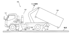
【課題】軌道載線などの作業を安全に行うことが可能な軌陸車を提供する。【解決手段】本考案は、車体102の前後左右に道路走行用車輪および軌道走行用車輪103を備え、道路走行時は前記道路走行用車輪103を用いて道路上を走行し、軌道走行時は前記軌道走行用車輪104を用いて軌道上を走行する軌陸車において、車輪152を前後左右に備え、前記車体102から取り外すし前記軌道上に載線することにより、前記軌道上の走行が可能であると共に、前記車体102に装着することにより、前記車体102と一体的に運搬されるコンテナ150と、前記コンテナ150を引っ掛けると共に、前記コンテナ150の積載状況に応じて前記コンテナ150を前記車体の前後に移動させるフック機構140と、を有することを特徴とする。【選択図】 図1A track-and-rail vehicle capable of safely performing operations such as track mounting is provided. The present invention includes road traveling wheels and track traveling wheels 103 on the front, rear, left and right sides of a vehicle body 102, traveling on the road using the road traveling wheels 103 when traveling on the road, and traveling during track traveling. In a track-and-rail vehicle that travels on a track using the track-traveling wheels 104, wheels 152 are provided on the front, rear, left, and right, and are removed from the vehicle body 102 and placed on the track, so that the vehicle can travel on the track. At the same time, by attaching to the vehicle body 102, the container 150 that is transported integrally with the vehicle body 102 and the container 150 are hooked, and the container 150 is attached to the front and rear of the vehicle body according to the loading situation of the container 150. And a hook mechanism 140 to be moved. [Selection] Figure 1
Description
本考案は、道路走行用車輪および軌道走行用車輪を備えて道路走行および軌道走行が可能である軌陸車に関する。 The present invention relates to a track-and-rail vehicle that includes road wheels and track wheels and is capable of road and track travel.
軌道上でトロリ線等の鉄道設備の工事・点検を行うため等に用いられる作業車である軌陸車は、トラックをベースとして構成されて車体の前後左右の4ヶ所に道路走行用車輪を備えるとともに、軌道走行用車輪が下方張出作動および上方格納作動自在に取り付けられており、道路上および軌道上の双方で走行可能である。 A track-and-rail vehicle, which is a work vehicle used for construction and inspection of railway facilities such as trolley lines on a track, is composed of a truck and has road driving wheels at four locations on the front, rear, left and right sides of the vehicle body. The wheel for traveling on the track is mounted so as to be able to operate in a downward projecting manner and an upward retracting operation, and can travel on both the road and the track.
このような軌陸車においては、荷台部分に土砂などを積載するためのスペースが設けられたものが知られている。(例えば、非特許文献1参照。)
軌陸車は、軌道への載線時、或いは軌道からの離脱時において、転車台装置によって、車両全体を持上げて支持し、旋回を行うが、従来の軌陸車においては、荷台の積載物の状況によっては、持ち上げ時のバランスが悪く、軌道載線などの作業工程が困難となる、という問題があった。 A railroad vehicle lifts and supports the entire vehicle by a turntable device when turning on or off the track, and turns, but in conventional railcars, the load on the platform is Depending on the situation, there is a problem that the balance at the time of lifting is poor and the work process such as track mounting becomes difficult.
上記のような課題を解決するために、請求項1に係る考案は、車体の前後左右に道路走行用車輪および軌道走行用車輪を備え、道路走行時は前記道路走行用車輪を用いて道路上を走行し、軌道走行時は前記軌道走行用車輪を用いて軌道上を走行する軌陸車において、車輪を前後左右に備え、前記車体から取り外すことにより、前記軌道上の走行が可能であると共に、前記車体に装着することにより、前記車体と一体的に運搬されるコンテナと、前記コンテナを引っ掛けると共に、前記コンテナの積載状況に応じて前記コンテナを前記車体の前後に移動させるフック機構と、を有することを特徴とする。 In order to solve the above-mentioned problems, the invention according to claim 1 is provided with road traveling wheels and track traveling wheels on the front, rear, left and right sides of the vehicle body, and the road traveling wheels are used on the road during the road traveling. In the track-and-rail vehicle that travels on the track using the track traveling wheel during the track traveling, the wheel is provided on the front and rear, left and right, and can be traveled on the track by removing from the vehicle body, A container that is transported integrally with the vehicle body by being attached to the vehicle body, and a hook mechanism that hooks the container and moves the container forward and backward of the vehicle body according to the loading situation of the container. It is characterized by that.
本考案の軌陸車によれば、コンテナの積載状況に応じてコンテナを車体の前後に移動させるように構成されているので、転車台装置による持ち上げ時などのバランスが向上し、軌道載線などの作業を安全に行うことが可能となる。 The track-and-rail vehicle of the present invention is configured to move the container forward and backward of the vehicle body according to the loading condition of the container. Work can be performed safely.
以下、本考案の実施の形態を図面を参照しつつ説明する。図1は本考案の実施の形態に係る軌陸車を側面側からみた概略を示す図である。図1は着脱可能なコンテナ150を装着した状態の本考案に係る軌陸車100を示している。また、図1に示す本考案に係る軌陸車100は、道路上にタイヤ車輪(道路走行用車輪)103により接地しており、道路上を走行可能な状況を示している。軌陸車100はトラック車両をベースとして、車両前部に運転キャビン121を有するとともに、車体102上に作業機材、作業資材等を積載して軌道上の作業現場まで運搬を可能とするコンテナ150と、車両全体の持上支持および旋回を行うための転車台装置108を有して構成される。
Hereinafter, embodiments of the present invention will be described with reference to the drawings. FIG. 1 is a diagram showing an outline of a rail vehicle according to an embodiment of the present invention as viewed from the side. FIG. 1 shows a
車体102の前後左右の4ヵ所には、タイヤ車輪(道路走行用車輪)103が取り付けられており、タイヤ車輪用エンジン(図示せず)により駆動して車体102が道路上を走行可能となっている。また、車体102の前後左右の4ヵ所には鉄輪(鉄道走行用車輪)104が車体102に揺動自在に支持された鉄輪支持部材105に回転自在に取り付けられている。鉄輪支持部材105は、鉄輪張出格納用シリンダ(不図示)の伸縮作動により揺動作動を行うように構成され、鉄輪104の下方への張出および車体102への格納が可能となっている。また、前後の各々において、左右の鉄輪104、104間は鉄道用レール(軌道)の幅に応じたピッチに可変となるように構成されている。軌陸車100は、鉄輪104を張り出した状態で車体102をレールに載線する。
Tire wheels (road driving wheels) 103 are attached to the front, rear, left and right of the
本考案に係る軌陸車100の車体102には、可動するフック機構140を有しており、このフック機構140によってコンテナ150の端部が引っ掛けられるようにして装着されている。コンテナ150は、上方部が開口しており、この開口から作業機材、作業資材、或いは作業により生じた残土等を積載したり、荷下ろししたりすることができるようになっている。コンテナ150の前後左右の4ヵ所には、軌道の幅と同じピッチの車輪152が設けられており、当該コンテナ150を軌道上に載線することができるようになっている。
The
図2は本考案の実施の形態に係る軌陸車100が転車台装置108によって持ち上げられた様子を示す図である。ここで、フック機構140は、コンテナ150の積載状況に応じてコンテナ150を車体の前後に移動させることができるようになっている。すなわち、フック機構140は、コンテナ150を車両前方のA側に移動させ、図2の実線で示すようにコンテナ150を保持したり、或いは、コンテナ150を車両後方のB側に移動させ、図2の点線で示すようにコンテナ150を保持したりすることができるようになっている。具体的には、コンテナ150の積載重量が大きいときにはコンテナ150を車両前方のA側に移動させ、コンテナ150の積載重量が小さいときにはコンテナ150を車両前方のB側に移動させることで、軌陸車100の車両前後のバランスを良くすることができる。
FIG. 2 is a view showing a state in which the
このような本考案の軌陸車100によれば、コンテナ150の積載状況に応じてコンテナ150を車体102の前後に移動させるように構成されているので、転車台装置108による持ち上げ時などのバランスが向上し、軌道載線などの作業を安全に行うことが可能となる。
According to such a track-and-
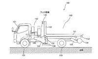
図3は本考案の実施の形態に係る軌陸車100が軌道に載線された様子を示す図である。このとき、転車台装置108による車体102の挙上が解除され、鉄輪支持部材105
によって鉄輪104が下方へ張り出され、鉄輪104が軌道上に乗った状態となり、軌陸車100は軌道上での走行ができるようになる。軌陸車100が走行するような状態でも、フック機構140は、コンテナ150を車両前方のA側に移動させ、図2の実線で示すようにコンテナ150を保持したり、或いは、コンテナ150を車両後方のB側に移動させ、図3の点線で示すようにコンテナ150を保持したりすることができるようになっている。具体的には、コンテナ150の積載重量が大きいときにはコンテナ150を車両前方のA側に移動させ、コンテナ150の積載重量が小さいときにはコンテナ150を車両前方のB側に移動させることで、軌陸車100の車両前後のバランスを良くすることができる。上記のようなフック機構140によれば、軌陸車100の走行中の車両前後の重量配分も適正化することができて、走行性が向上する。
FIG. 3 is a diagram illustrating a state in which the track-and-
As a result, the
図4は本考案の実施の形態に係る軌陸車100からコンテナ150を着脱する様子を示す図である。フック機構140は図示するように起倒することができるようにされており、これにより、コンテナ150を車体102から取り外したり、逆に、コンテナ150を車体102に装着したりすることができるようになっている。
FIG. 4 is a diagram showing a state in which the
図5は本考案の実施の形態に係る軌陸車100からコンテナ150を切り離して、コンテナ150を軌道上に載線した様子を示す図である。このとき、コンテナ150の前後左右の4ヵ所に設けられた車輪152が軌道上に乗った状態となる。図5は軌陸車100からコンテナ150を完全に切り離した状態を示しているが、コンテナ150を軌陸車100によって牽引することによって、コンテナ150を軌道上で移動させるように運用することもできる。このような牽引を行う場合には、図6に示すようにフック機構140によってコンテナ150を引っ掛けると共に、適当な連結部170によって、車体102とコンテナ150とを連結するように構成することが好ましい。
FIG. 5 is a diagram illustrating a state in which the
上記のように、軌道上に載線されたコンテナ150に基づいた作業は、不図示の架線からの距離が離れることとなるので、安全性が担保されると共に、コンテナ150上方の開口部も低い位置にくるようになることから、作業効率も向上する。
As described above, since the work based on the
以上、本考案の軌陸車100によれば、コンテナ150の積載状況に応じてコンテナ150を車体102の前後に移動させるように構成されているので、転車台装置108による持ち上げ時などのバランスが向上し、軌道載線などの作業を容易に行うことが可能となる。
As mentioned above, according to the track-and-
次に本考案の他の実施形態について説明する。図7は本考案の他の実施形態に係る軌陸車100を示す図である。図7において、第1の実施形態と同様の参照符号が付されている構成は同様のものを示しているので、説明を省略する。図7に示す実施形態が、第1の実施形態と相違する点は、上方に開口部を有するコンテナ150に代えて、作業機械等運搬コンテナ180が用いられている点である。作業機械等運搬コンテナ180は、底板部181とこれと垂直に立設した側板部182とを有し、3方に側板がない構造となっている。作業機械等運搬コンテナ180においては、車輪152は底板部181に設けられている。このような作業機械等運搬コンテナ180においては、3方に側板がない構造であるために、作業機械等の搭載・荷下ろしなどの作業が容易に行えるようになっている。
Next, another embodiment of the present invention will be described. FIG. 7 is a view showing a track-and-
なお、図7に示す作業機械等運搬コンテナ180の底板部181には、専用の作業機械(例えば、ミキサーなど)を固着し、用途を特化したものとすることもできる。
Note that a dedicated work machine (for example, a mixer or the like) may be fixed to the
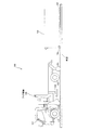
次に本考案の他の実施形態について説明する。図8は本考案の他の実施形態に係る軌陸車100を示す図である。図8において、第1の実施形態と同様の参照符号が付されている構成は同様のものを示しているので、説明を省略する。
Next, another embodiment of the present invention will be described. FIG. 8 is a view showing a track-and-
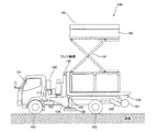
図8に示す実施形態が、これまでの実施形態と相違する点は、コンテナとしてリフタ装置191が設けられたリフタ装置付きコンテナ190が用いられている点である。リフタ装置191は軌陸車100に設けられている油圧装置(不図示)から駆動力を得て作業台192の昇降を行うものである。例えば、第1実施形態などのコンテナ部分を、図8に示すリフタ装置付きコンテナ190に取り替えることにより、1つの車体102を、架線な
どの点検修理にも利用することが可能となる。
The embodiment shown in FIG. 8 is different from the previous embodiments in that a
100・・・軌陸車
102・・・車体
103・・・タイヤ車輪(道路走行用車輪)
104・・・鉄輪(鉄道走行用車輪)
105・・・鉄輪支持部材
108・・・転車台装置
121・・・運転キャビン
140・・・フック機構
150・・・コンテナ
152・・・車輪
170・・・連結部
180・・・作業機械等運搬コンテナ
181・・・底板部
182・・・側板部
190・・・リフタ装置付きコンテナ
191・・・リフタ装置
192・・・作業台
DESCRIPTION OF
104 ... Iron wheel (Railway wheel)
105 ... Iron
Claims (4)
車輪を前後左右に備え、前記車体から取り外し前記軌道上に載線することにより、前記軌道上の走行が可能であると共に、前記車体に装着することにより、前記車体と一体的に運搬されるコンテナと、
前記コンテナを引っ掛けると共に、前記コンテナの積載状況に応じて前記コンテナを前記車体の前後に移動させるフック機構と、を有することを特徴とする軌陸車。 Road running wheels and track running wheels are provided on the front, rear, left and right sides of the vehicle body, and when traveling on the road, the road running wheels are used to travel on the road, and during track running, the track running wheels are used to travel on the track. In a running track-and-rail vehicle,
Containers that are equipped with wheels on the front, rear, left and right, are removed from the vehicle body, and placed on the track so that the vehicle can travel on the track, and the container that is mounted on the vehicle body is transported integrally with the vehicle body. When,
A rail vehicle having a hook mechanism for hooking the container and moving the container forward and backward of the vehicle body according to a loading state of the container.
Priority Applications (1)
| Application Number | Priority Date | Filing Date | Title |
|---|---|---|---|
| JP2011000416U JP3167166U (en) | 2011-01-28 | 2011-01-28 | Railroad car |
Applications Claiming Priority (1)
| Application Number | Priority Date | Filing Date | Title |
|---|---|---|---|
| JP2011000416U JP3167166U (en) | 2011-01-28 | 2011-01-28 | Railroad car |
Publications (1)
| Publication Number | Publication Date |
|---|---|
| JP3167166U true JP3167166U (en) | 2011-04-07 |
Family
ID=54878274
Family Applications (1)
| Application Number | Title | Priority Date | Filing Date |
|---|---|---|---|
| JP2011000416U Expired - Fee Related JP3167166U (en) | 2011-01-28 | 2011-01-28 | Railroad car |
Country Status (1)
| Country | Link |
|---|---|
| JP (1) | JP3167166U (en) |
Cited By (2)
| Publication number | Priority date | Publication date | Assignee | Title |
|---|---|---|---|---|
| JP2016190538A (en) * | 2015-03-31 | 2016-11-10 | 株式会社タダノ | Railroad vehicle turntable operation restriction device |
| CN107585182A (en) * | 2017-10-19 | 2018-01-16 | 浙江益能建材科技有限公司 | Porous brick carrier |
-
2011
- 2011-01-28 JP JP2011000416U patent/JP3167166U/en not_active Expired - Fee Related
Cited By (2)
| Publication number | Priority date | Publication date | Assignee | Title |
|---|---|---|---|---|
| JP2016190538A (en) * | 2015-03-31 | 2016-11-10 | 株式会社タダノ | Railroad vehicle turntable operation restriction device |
| CN107585182A (en) * | 2017-10-19 | 2018-01-16 | 浙江益能建材科技有限公司 | Porous brick carrier |
Similar Documents
| Publication | Publication Date | Title |
|---|---|---|
| CN104608680A (en) | Electric carrier for road car barrier clearance | |
| WO2021051786A1 (en) | Bidirectional driving traction and cargo-carrying transport vehicle for use on both highway and railway | |
| JP4397716B2 (en) | Heavy object placement method and system | |
| JP5698437B2 (en) | Toro for transporting equipment | |
| CN104670349A (en) | Semitrailer capable of automatically loading and unloading goods | |
| JP3136222U (en) | Luggage unloading device | |
| CN105644570B (en) | One kind carries back of the body formula transport New Type of Railway Freight Cars on the back | |
| CN201646505U (en) | Van cargo handling device | |
| JP3167166U (en) | Railroad car | |
| CN201646503U (en) | Van cargo loading device | |
| CN103522932B (en) | Car transporter | |
| US11629036B2 (en) | Outrigger pad hoist apparatus | |
| JP2020521665A (en) | Equipment for transporting welded long rails | |
| JP7430884B2 (en) | Track maintenance work vehicle transportation trolley and track maintenance work vehicle transportation method | |
| CN205634748U (en) | Railway freight car fork truck lifting machine | |
| CN105236273A (en) | Hoisting machine for wheeled automobiles | |
| JP2991156B2 (en) | Cargo handling equipment using cranes | |
| JP2012056557A (en) | Road rail working vehicle | |
| CN102838044B (en) | Tunnel rescue crane | |
| CN215479155U (en) | A non-standard automatic loading and unloading crane platform | |
| JP3253764U (en) | Trolley | |
| JP6575245B2 (en) | Railroad work vehicle | |
| JP6485011B2 (en) | Crane-type gauge land vehicle | |
| JP3215244U (en) | Truck with crane | |
| JPH04345431A (en) | Freight car loading device |
Legal Events
| Date | Code | Title | Description |
|---|---|---|---|
| R150 | Certificate of patent or registration of utility model |
Ref document number: 3167166 Country of ref document: JP Free format text: JAPANESE INTERMEDIATE CODE: R150 |
|
| R250 | Receipt of annual fees |
Free format text: JAPANESE INTERMEDIATE CODE: R250 |
|
| R250 | Receipt of annual fees |
Free format text: JAPANESE INTERMEDIATE CODE: R250 |
|
| R250 | Receipt of annual fees |
Free format text: JAPANESE INTERMEDIATE CODE: R250 |
|
| R250 | Receipt of annual fees |
Free format text: JAPANESE INTERMEDIATE CODE: R250 |
|
| R250 | Receipt of annual fees |
Free format text: JAPANESE INTERMEDIATE CODE: R250 |
|
| LAPS | Cancellation because of no payment of annual fees |