JP3141032U - Duct integrated ventilation louver - Google Patents
Duct integrated ventilation louver Download PDFInfo
- Publication number
- JP3141032U JP3141032U JP2008000641U JP2008000641U JP3141032U JP 3141032 U JP3141032 U JP 3141032U JP 2008000641 U JP2008000641 U JP 2008000641U JP 2008000641 U JP2008000641 U JP 2008000641U JP 3141032 U JP3141032 U JP 3141032U
- Authority
- JP
- Japan
- Prior art keywords
- duct
- ventilation
- ventilation duct
- louver
- building
- Prior art date
- Legal status (The legal status is an assumption and is not a legal conclusion. Google has not performed a legal analysis and makes no representation as to the accuracy of the status listed.)
- Expired - Fee Related
Links
Images


Abstract
【課題】建物内に設置された換気ダクトへの接続作業が簡便になり、経済的に施行できるばかりでなく、充分な通気性を確保しつつ、高い防水・防雪性能及び排水性能を得ることができるダクト一体型換気ルーバを提供する
【解決手段】複数の羽根板1aが配されたガラリ部1を、建物の外壁を貫通する略縦筒状の通気ダクト2の屋外面の下端側に開口されたガラリ取付口2dに嵌装固定する。通気ダクト2の上部屋内面に、このガラリ部1よりも上位置に、建物内の換気ダクト3と接続される貫通口2cを設け、そのフランジ2aと換気ダクト3のフランジ3aとをボルト締結して接続できるようにする。
【選択図】 図1[PROBLEMS] To easily connect to a ventilation duct installed in a building and perform it economically, and to obtain high waterproof / snowproof performance and drainage performance while ensuring sufficient air permeability. Provided is a duct-integrated ventilation louver capable of opening a gallery portion 1 provided with a plurality of blades 1a to the lower end side of the outdoor surface of a substantially vertical cylindrical ventilation duct 2 that penetrates the outer wall of a building. It is fitted and fixed to the louver attachment port 2d. A through-hole 2c connected to the ventilation duct 3 in the building is provided on the inner surface of the upper chamber of the ventilation duct 2 at a position higher than the gallery portion 1, and the flange 2a and the flange 3a of the ventilation duct 3 are bolted to each other. To be able to connect.
[Selection] Figure 1
Description
本考案は、建物の開口部等に取り付けて通気を良好にし、且つ雨水の侵入を防ぐために使用される換気ルーバ、通称ガラリと呼ばれる建具に関し、とくに工場等の換気ダクトと直結が可能なダクト一体型換気ルーバに関するものである。 The present invention relates to a ventilation louver used to improve ventilation and prevent intrusion of rainwater by attaching it to an opening of a building or the like, and a fitting called a galley. It relates to body ventilation louvers.
従来、工場、発電所、体育館、倉庫、ビル、家屋等の建物の排気口などの開口部に取付けられる換気ルーバは、基本的には複数の羽根板を所定の枠体に横方向あるいは縦方向に格子状に並べた構成とされている。 Conventionally, ventilation louvers that are attached to openings such as exhaust ports of buildings such as factories, power plants, gymnasiums, warehouses, buildings, houses, etc. basically have a plurality of blades in a horizontal or vertical direction with a predetermined frame. Are arranged in a grid pattern.
ところで、例えば、工場等の空調設備において、建物外壁に換気ダクトに連結される開口部を設け、この開口部にガラリを取り付ける場合、建物内部と外部では、別種の工事となるため、異なる工事業者が共同で或いは別々に施行する必要があり、作業の煩雑化及び施行コストが嵩むといった問題があった。すなわち、壁面にガラリを取付ける者と、ガラリと換気ダクトの連結作業をする者が異なってしまうという課題があった。 By the way, for example, in an air conditioner such as a factory, when an opening connected to a ventilation duct is provided on the outer wall of a building and a gallery is attached to this opening, it is a different type of work inside and outside the building, so different contractors However, there is a problem that it is necessary to perform jointly or separately, which complicates the work and increases the cost of execution. That is, there is a problem that the person who attaches the louver to the wall surface is different from the person who connects the louver and the ventilation duct.
そこで、グラスウール繊維等の吸音材を充填して成る通気ダクトがガラリの通気経路延長上に一体的に設けてなるもの(特許文献1参照。)。扉本体内を中空にし、その内部にセパレータを兼ねた補強材を配設し、この補強材によって扉本体内に形成されたダクトの各々の端部に位置するようにして扉表面と扉裏面の各々に正面ガラリ及び裏面ガラリを配設したガラリ扉(特許文献2参照。)。住宅の壁を貫通するダクト状の壁貫通部材と、住宅の外に取付けるボックス状の屋外部材とからなり、屋外部材に下面開口と下面開口より上位且つ背面で壁貫通部材に連結するダクト接続口を供えた住宅用吸気ガラリ(特許文献3参照。)。パネル体の一側からパネル体の内部に向けて空間を形成し、この空間にユニットに形成したガラリを収納したもの(特許文献4参照。)等が提案されている。 Therefore, a ventilation duct formed by filling a sound absorbing material such as glass wool fiber is integrally provided on the extension of the ventilation path of the gallery (see Patent Document 1). The interior of the door body is hollow, and a reinforcing material that also serves as a separator is provided inside the door body. The reinforcing material is positioned at each end of the duct formed in the door body so that the door surface and the back surface of the door are positioned. A louver door in which a front louver and a back louver are provided for each (see Patent Document 2). A duct connection port that includes a duct-shaped wall penetrating member that penetrates the wall of the house and a box-shaped outdoor member that is attached to the outside of the house, and is connected to the wall penetrating member at the lower surface opening and the lower surface opening and on the rear surface. An air intake gallery for a house (see Patent Document 3). There has been proposed a structure in which a space is formed from one side of the panel body toward the inside of the panel body, and a gallery formed in the unit is stored in this space (see Patent Document 4).
しかしながら、上記従来の装置においては、ガラリと換気ダクトとを接続するための別部材を要するばかりでなく、雨水や雪の浸入を確実に防止できる構造であるとは言いがたい。本考案は、建物内に設置された換気ダクトへの接続作業が簡便になり、経済的に施行できるばかりでなく、充分な通気性を確保しつつ、高い防水・防雪性能及び排水性能を得ることができるダクト一体型換気ルーバを提供することを目的とするものである。 However, the above-described conventional apparatus requires not only a separate member for connecting the louver and the ventilation duct, but also cannot be said to have a structure that can reliably prevent rainwater and snow from entering. The present invention makes it easy to connect to a ventilation duct installed in a building, which can be carried out economically, and obtains high waterproof / snowproof performance and drainage performance while ensuring sufficient ventilation. An object of the present invention is to provide a duct-integrated ventilation louver.
そこで、本考案のダクト一体型換気ルーバは、建物の外壁を貫通する略縦筒状の通気ダクトの屋外面にガラリ部を配置し、このガラリ部よりも上位置の屋内面に、建物内に設置された換気ダクトとの接続口を設けたことを第1の特徴とする。また、通気ダクトの内部角隅に湾曲板を配したことを第2の特徴とする。さらに、通気ダクトの立上がり面に水返し部を設けたことを第3の特徴とする。 Therefore, the duct-integrated ventilation louver of the present invention has a louvered portion on the outdoor surface of a substantially vertical cylindrical ventilation duct that penetrates the outer wall of the building, and is placed on the indoor surface above the louvered portion in the building. The first feature is that a connection port with the installed ventilation duct is provided. In addition, a second feature is that a curved plate is disposed at the internal corner of the ventilation duct. Furthermore, a third feature is that a water return portion is provided on the rising surface of the ventilation duct.
本考案によれば、以下の優れた効果がある。
(1)異なる工事業者が共同で或いは別々に施行する必要がなく、また、ガラリと屋内換気ダクトを接続するための部材が不要になるので、作業の煩雑化及び施行コストが削減できる。
(2)風洞の外部下面にガラリを配置し、このガラリよりも上位置の内部上面に、通気ダクトとの連結口を設けたので、雨水や雪の浸入を確実に防止できる。
(3)通気ダクトの内部角隅に湾曲板を配したことにより、流通する空気の圧力損失を低減することができ高い通気性が確保できる。
(4)通気ダクトの立上がり面に水返し部を設けたことにより、高い防水・防雪性能及び排水機能を得ることができる。
The present invention has the following excellent effects.
(1) It is not necessary for different construction contractors to perform jointly or separately, and since a member for connecting the gallery and the indoor ventilation duct is not required, the work is complicated and the execution cost can be reduced.
(2) Since the louver is arranged on the outer lower surface of the wind tunnel and the connection port with the ventilation duct is provided on the inner upper surface above the louver, the intrusion of rainwater and snow can be surely prevented.
(3) Since the curved plate is disposed at the internal corners of the ventilation duct, the pressure loss of the circulating air can be reduced and high air permeability can be ensured.
(4) By providing the water return portion on the rising surface of the ventilation duct, high waterproof / snowproof performance and drainage function can be obtained.
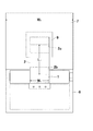
以下、本考案の実施の形態を図面に示す実施例に基づいて説明する。図1は本考案に係るダクト一体型換気ルーバの一実施例を示す(a)は正面図、(b)は側面図、図2は本考案に係るダクト一体型換気ルーバの要部側面断面図、図3は防水試験装置を示す正面図、図4は防水試験装置を示す一部断面側面図、図5及び図6は試験で用いたガラリの仕様を示す(a)は正面図、(b)は横断面図である。 Hereinafter, embodiments of the present invention will be described based on examples shown in the drawings. FIG. 1 shows an embodiment of a duct-integrated ventilation louver according to the present invention. FIG. 1A is a front view, FIG. 2B is a side view, and FIG. 3 is a front view showing the waterproof test apparatus, FIG. 4 is a partially sectional side view showing the waterproof test apparatus, FIGS. 5 and 6 show the specifications of the galley used in the test, FIG. ) Is a cross-sectional view.
図1乃至図3において、1は、複数の羽根板1aが配されたガラリ部で、建物の外壁を貫通する略縦筒状の通気ダクト2の屋外面の下端側に開口されたガラリ取付口2bに嵌装固定される。通気ダクト2の上部屋内面には、このガラリ部1よりも上位置に、建物内の換気ダクト3と接続される貫通口2cが設けられており、そのフランジ2aと換気ダクト3のフランジ3aとをボルト締結して接続できるようにされている。
In FIG. 1 to FIG. 3,
また、通気ダクト2の内部の下部角隅には内向きに凹状にされた第1湾曲板4が、上部角隅にも内向きに凹状にされた第2湾曲板5が取付けられており、通気ダクト2内を流通する空気の圧力損失を低減することができるようにされている。さらに、通気ダクト2の立上がり面2dには、下方に向かって鋭角に屈曲して形成された第1屈折帯板6a及び第2屈曲帯板6bと水返し板6とからなる水返し部が設けられ、ガラリ部1を通過して侵入してきた雨水や雪を捕捉して流下することができるようにされている。
In addition, a first
水返し板6は、立上がり面2dと若干の間隙D1をもって配置されており、この隙間D1は、水返し板6の上方に設けられた第1屈折帯板6aで捕捉された雨水や雪が流下する流路を形成することになる。
図3乃至図6に示すように、ガラリ部1は、アルミサッシ製の固定枠12に複数の横羽根板1a、1a…が一体的に連設された屋外面14と、内側面15とを備えており、通常は、この屋内面15が室内に臨む状態で建物の開口部に固定枠12ごと取り付けられる構成とされている。さらに、ガラリ部1の屋内面側には網体(ネット)1bが張設されている。ネット1bの網目度は60メッシュ程度で、雪は捕捉するが、スムーズに通気できる網目サイズを用いるのが好ましい。このように、ガラリ部1の全面を覆う網体1bにより、より確実な防雪性能を得ることができる。
As shown in FIGS. 3 to 6, the
羽根板1a、1a…はアルミ製の板材からなり、下方に向かって傾斜した傾斜面13が形成され、この傾斜面13の下端には平板が垂設され、略く字形状をなしている。本実施例ではこの傾斜面13は直線的に形成されているが、下方に湾曲した形状であってもよい。また、羽根板1a、1a…は、上下方向に一定間隔置きに配設されるので、上下方向に一定間隔置きに横長孔状の複数の間隙(通気路)11、11…が形成される。
The
すなわち、上記のように構成される羽根板1a、1a…を互いに平行に並べ、枠体12内に固定する。その際、各羽根板1a、1a…は、隣接するもの同士の間において、その上下端がお互い重なり合うように位置させ、且つ、間隙(通気路)11が形成されるように並設する。
That is, the
また、最下端の羽根板1aには前方に延出してスカート部1cが設けられており、雨水が内部に吹き込まないようにされている。このように、ルーバ1の下端部前面を覆うスカート部1cにより、下方から巻き上がる雨水や雪に対する確実な防水及び防雪性能を得ることができる。
Further, the
[試験例]
図7及び図8に示す試験装置を用いて本考案に係る換気ルーバの防水試験を行った。結果を表1に示す。
試験装置は、前面に窓口7aを開口した防水試験用風洞7を架台8に載置して固定ボルト10で締結固定し、ダクト部2の貫通口2cを風洞7の窓口7aにパッキング9を介して気密状態に固定し連通した。
試験装置の各寸法は次のとおりである。尚、ガラリ部としては、図3及び図4に示す1枚羽根ガラリと図5及び図6に示す2枚羽根ガラリを用いた。
風洞の横幅:W2=1800mm
風洞の高さ:H1=2170mm
風洞の奥行:L4=3600
開口部の幅:W1=500mm
開口部から排気口までの距離:L1=1000mm
開口部の縦寸法:L2=500mm
排気口の縦寸法:L3=510mm
架台から排気口の中心までの高さ:H2=1160mm
[Test example]
A waterproof test of the ventilation louver according to the present invention was performed using the test apparatus shown in FIGS. The results are shown in Table 1.
The test apparatus places a waterproof
The dimensions of the test apparatus are as follows. In addition, as a louver part, the 1 sheet | seat louver shown in FIG.3 and FIG.4 and the 2 sheet | seat louver shown in FIG.5 and FIG.6 were used.
Wind tunnel width: W 2 = 1800mm
Wind tunnel height: H 1 = 2170 mm
Depth of wind tunnel: L 4 = 3600
Opening width: W 1 = 500 mm
Distance from the opening to the exhaust port: L 1 = 1000 mm
Vertical dimension of opening: L 2 = 500 mm
Vertical dimension of exhaust port: L 3 = 510 mm
Height from the gantry to the center of the exhaust port: H 2 = 1160mm
水量:4リットル/分×10分=40リットルを風速10m/s〜34/sで噴霧して、ダクトの間取り寸法D2を100mmと300mmに変化させ、防水試験を行った。結果を表1に示す。 Water: 4 liters / minute × 10 minutes = 40 liters sprayed at wind velocity 10m / s~34 / s, the floor plan dimensions D 2 of the duct is varied in 100mm and 300 mm, it was subjected to waterproof test. The results are shown in Table 1.
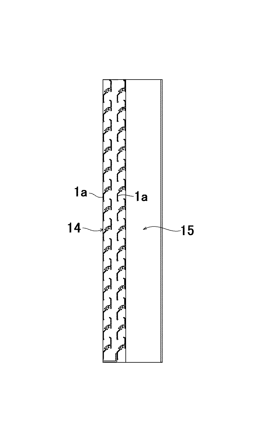
表1から明らかなように、本考案に係るダクト一体型換気ルーバは、各条件下において、ほぼ確実な防水効果が発揮された。 As is clear from Table 1, the duct-integrated ventilation louver according to the present invention exhibited a substantially reliable waterproof effect under each condition.
1 ガラリ部
1a 羽根板
1b 防虫網
1c スカート部
2 ダクト部
2a フランジ
2b ガラリ取付口
2c 貫通口
2d 立上り面
3 換気ダクト接続口
3 換気ダクト
4 第1湾曲板
5 第2湾曲板
6 水返し板
6a 第1屈折帯板
6b 第2屈折帯板
7 防水試験用風洞
7a 窓口
8 架台
9 パッキング
10 固定ボルト
11 羽根板の間隙(通気路)
12 固定枠
13 羽根板の傾斜面
14 ガラリ部の屋外面
15 ガラリ部の屋内面
DESCRIPTION OF
12
Claims (3)
Priority Applications (1)
| Application Number | Priority Date | Filing Date | Title |
|---|---|---|---|
| JP2008000641U JP3141032U (en) | 2008-02-08 | 2008-02-08 | Duct integrated ventilation louver |
Applications Claiming Priority (1)
| Application Number | Priority Date | Filing Date | Title |
|---|---|---|---|
| JP2008000641U JP3141032U (en) | 2008-02-08 | 2008-02-08 | Duct integrated ventilation louver |
Publications (1)
| Publication Number | Publication Date |
|---|---|
| JP3141032U true JP3141032U (en) | 2008-04-17 |
Family
ID=43291114
Family Applications (1)
| Application Number | Title | Priority Date | Filing Date |
|---|---|---|---|
| JP2008000641U Expired - Fee Related JP3141032U (en) | 2008-02-08 | 2008-02-08 | Duct integrated ventilation louver |
Country Status (1)
| Country | Link |
|---|---|
| JP (1) | JP3141032U (en) |
Cited By (1)
| Publication number | Priority date | Publication date | Assignee | Title |
|---|---|---|---|---|
| CN113266255A (en) * | 2020-02-17 | 2021-08-17 | 珠海兴业绿色建筑科技有限公司 | Novel environment-friendly energy-saving building curtain wall shutter system capable of effectively improving outer enclosure performance of building |
-
2008
- 2008-02-08 JP JP2008000641U patent/JP3141032U/en not_active Expired - Fee Related
Cited By (1)
| Publication number | Priority date | Publication date | Assignee | Title |
|---|---|---|---|---|
| CN113266255A (en) * | 2020-02-17 | 2021-08-17 | 珠海兴业绿色建筑科技有限公司 | Novel environment-friendly energy-saving building curtain wall shutter system capable of effectively improving outer enclosure performance of building |
Similar Documents
| Publication | Publication Date | Title |
|---|---|---|
| JP5379557B2 (en) | Venting material and exterior wall structure of buildings | |
| ITVI20060324A1 (en) | PROTECTIVE STRUCTURE, PARTICULARLY FOR AIR-CONDITIONERS. | |
| JP2009084962A (en) | Waterproof and snow protection type ventilation louvre | |
| JP3141032U (en) | Duct integrated ventilation louver | |
| JP2012225005A (en) | Rainproof panel for dwelling | |
| JP7262158B1 (en) | Ventilation device and eaves ventilation structure using the same | |
| JP5054304B2 (en) | Ventilation box and waist wall ventilation structure | |
| JP3143015U (en) | Duct integrated ventilation louver | |
| JP5374283B2 (en) | Ventilation structure and building | |
| JP5613343B2 (en) | Ventilation structure and building | |
| JP4094628B2 (en) | Large balcony | |
| JP6962542B2 (en) | Kasagi structure | |
| JP4034084B2 (en) | Water stoppage structure between the roof and the outer wall | |
| JP5466481B2 (en) | Ventilation structure and building | |
| JP2019082089A (en) | building | |
| JP5524988B2 (en) | Ventilation structure and building | |
| JP4789440B2 (en) | Ventilation method for walls, balcony railings, buildings, and wall spaces | |
| JP6958224B2 (en) | Wall ventilation structure | |
| JP5964059B2 (en) | building | |
| JP6774202B2 (en) | Buildings and ventilation towers | |
| JP5993118B2 (en) | Exterior wall structure | |
| JPH079999Y2 (en) | Ventilation window | |
| JP5676999B2 (en) | Building outer wall structure | |
| JP5676998B2 (en) | Building outer wall structure | |
| JP2012241313A (en) | Outer wall structure |
Legal Events
| Date | Code | Title | Description |
|---|---|---|---|
| R150 | Certificate of patent or registration of utility model |
Free format text: JAPANESE INTERMEDIATE CODE: R150 |
|
| FPAY | Renewal fee payment (event date is renewal date of database) |
Free format text: PAYMENT UNTIL: 20110326 Year of fee payment: 3 |
|
| LAPS | Cancellation because of no payment of annual fees |