JP3111663U - Locking device for back cover of gaming machine - Google Patents
Locking device for back cover of gaming machine Download PDFInfo
- Publication number
- JP3111663U JP3111663U JP2005002381U JP2005002381U JP3111663U JP 3111663 U JP3111663 U JP 3111663U JP 2005002381 U JP2005002381 U JP 2005002381U JP 2005002381 U JP2005002381 U JP 2005002381U JP 3111663 U JP3111663 U JP 3111663U
- Authority
- JP
- Japan
- Prior art keywords
- locking device
- cover
- gaming machine
- back cover
- wall member
- Prior art date
- Legal status (The legal status is an assumption and is not a legal conclusion. Google has not performed a legal analysis and makes no representation as to the accuracy of the status listed.)
- Expired - Lifetime
Links
Images
Landscapes
- Pinball Game Machines (AREA)
Abstract
【課題】 遊技機の勝率を制御するROM等の不正操作を防止するため裏側カバーを施錠することのできる施錠装置を提供する。
【解決手段】 底壁部材16とこれに直交する4つの側壁部材を有し、側壁部材の後端縁が開口部となるケース本体18と、ケース本体の開口部を塞ぐ蓋体19とからなり、ケース本体の開口部を形成する対向する一対の平行な側壁部材に掛け金との掛合用スリット20、20がそれぞれ穿設され、底壁部材16には、遊技機の前面枠の裏側に設けられた裏側カバー押さえ止め具の挿通用孔22が穿設されており、蓋体の錠取着用板部23に取着されたシリンダー錠24の錠軸24aが蓋体の内側に突出し、錠軸に掛け金25が固定されてなる。
【選択図】 図2PROBLEM TO BE SOLVED: To provide a locking device capable of locking a back cover in order to prevent unauthorized operation of a ROM or the like for controlling a winning rate of a gaming machine.
SOLUTION: A bottom wall member 16 and four side wall members orthogonal to the bottom wall member 16 are provided. The side wall member includes a case main body 18 whose rear end edge is an opening, and a lid 19 that closes the opening of the case main body. The pair of parallel side wall members that form the opening of the case body are respectively provided with slits 20 and 20 for engaging with the latch, and the bottom wall member 16 is provided on the back side of the front frame of the gaming machine. The back cover presser stopper insertion hole 22 is formed, and the lock shaft 24a of the cylinder lock 24 attached to the lock mounting plate portion 23 of the lid projects to the inside of the lid, The latch 25 is fixed.
[Selection] Figure 2
Description
この考案は、遊技機の裏側カバーの施錠装置に関するものである。さらに詳しくは、この考案は、パチンコ、パチスロ、スロットマシン、スマートボール、アレンジボールに例示される遊技機への不正操作を防止するための裏側カバーを施錠するための施錠装置に関するものである。 This invention relates to a locking device for a back cover of a gaming machine. More specifically, the present invention relates to a locking device for locking a back side cover for preventing unauthorized operation of a gaming machine exemplified by a pachinko machine, a pachislot machine, a slot machine, a smart ball, and an arrange ball.
パチンコ機等の遊技機の前面枠は、一端が蝶番で本体枠に固定され、他端は自由端として本体枠に対し回動可能となっており、前面枠の背面の自由端側に本体枠との施錠を可能とする前面枠用の施錠装置が設けられている(例えば、特許文献1参照。)
特許文献1に記載の前面枠用の施錠装置は、例えば、前面枠と本体枠との間の僅かな間隙から、先端にフックが形成された帯状で薄い鋼板や先端が折り曲げられてフックが形成されたピアノ線のような不正操作具を挿入し、施錠装置の鉤部にフックを係止させ、施錠装置を解錠し、前面枠を本体枠から開放させ、前面枠の裏側に配設された機器や部品を改変したり、遊技機の勝率を制御するROMを勝率の高い裏ROMと交換する等の不正操作を防止しようとするものである。
特許文献1に記載の前面枠用の施錠装置は、前記したようなフックを有する操作具を用いた遊技機への不正操作に対しては有効であるが、不正に入手した合い鍵等が使用された場合には、十分とはいえない。
The locking device for the front frame described in
The locking device for the front frame described in
そこで、前面枠用の施錠装置による遊技機への不正操作を防止することに加え、遊技機の前面枠の裏側に配設された機器や部品のうち、例えば、遊技機の勝率を制御するROMを備えた制御基板をケースに入れ、これを封止シールで封止し、封止シールを破損しない限りケースを開けることができないようにし、封止シールが破損されていれば、不正操作がなされたことが分かるようにしたり、機器や部品を覆う裏側カバーを設け、同様に、封止シールで封止し、封止シールを破損しない限り裏側カバーを開けることができないようにし、封止シールの破損がある場合は、不正操作がなされたことが容易に分かるようにすることが行われている。
しかしながら、不正目的で封止シールが剥がされ、不正操作が行われ、封止シールと同種のシールや類似したシールが貼り直されたりすると、不正操作が行われた遊技機を見出すことは困難である。また、封止シールでは、遊技機の検査時や故障時の部品の交換等に際し、封止を剥がし、その後、新たな封止シールで封止し直さねばならないこと等から面倒である。
Therefore, in addition to preventing unauthorized operation of the gaming machine by the locking device for the front frame, among the devices and parts arranged on the back side of the front frame of the gaming machine, for example, a ROM that controls the winning percentage of the gaming machine Put the control board with a case in it and seal it with a sealing seal so that the case cannot be opened unless the sealing seal is damaged. In the same way, provide a back cover that covers equipment and components, and similarly seal with a sealing seal so that the back cover cannot be opened unless the sealing seal is damaged. If there is damage, it is easy to know that an unauthorized operation has been performed.
However, if the sealing seal is peeled off for illegal purposes, an unauthorized operation is performed, and a seal of the same type as the sealing seal or a similar seal is reapplied, it is difficult to find a gaming machine in which the unauthorized operation has been performed. is there. In addition, the sealing seal is troublesome because it is necessary to peel off the seal at the time of inspection of the gaming machine or replacement of parts at the time of failure, and then re-seal with a new sealing seal.
この考案は、上記のような実情に鑑み鋭意研究の結果創案されたものであり、遊技機の前面枠の裏側に配設された機器や部品への不正操作を確実にかつ簡便に防止すること、より具体的には、遊技機への不正操作を防止するため裏側カバーを施錠することのできる施錠装置を提供することを目的としている。 This device was created as a result of intensive research in view of the above situation, and reliably and easily prevent unauthorized operation of equipment and parts arranged on the back side of the front frame of the gaming machine. More specifically, an object of the present invention is to provide a locking device that can lock the back cover to prevent unauthorized operation of the gaming machine.
上記課題を解決するために、この考案は、(i)遊技機の前面枠裏側に配設された裏側カバーを施錠する施錠装置であって、底壁部材とこれに直交する側壁部材を有するケース本体と、該ケース本体の蓋体とからなり、前記ケース本体の側壁部材には一対の掛け金との掛合用スリットが対向して穿設され、底壁部材には、遊技機の前面枠の裏側に回動可能に軸支された裏側カバー押さえ止め具を挿通する挿通用孔が穿設されており、前記蓋体の内側に、蓋体の錠取着用板部に取着されたシリンダー錠の錠軸が突出し、該錠軸に掛け金が固定されてなることを特徴とする。 In order to solve the above-described problems, the present invention provides (i) a locking device for locking a back side cover disposed on the back side of a front frame of a gaming machine, the case having a bottom wall member and a side wall member orthogonal thereto. The side wall member of the case body has a slit for engaging with a pair of latches facing each other, and the bottom wall member has a back side of the front frame of the gaming machine. An insertion hole for inserting a back side cover holding stopper pivotally supported on the inner side of the cover is formed, and a cylinder lock attached to the lock mounting plate portion of the lid is formed inside the lid. The lock shaft protrudes, and a latch is fixed to the lock shaft.
(ii)前記(i)において、前記ケース本体は、互いに直交する4つの側壁部材からなり、このうち一対の対向する側壁部材に掛け金との掛合用スリットがそれぞれ穿設されてなるものであることが好ましい。
(iii)前記(i)または(ii)において、前記ケース本体の挿通用孔が、遊技機の前面枠の裏側に設けられたバタフライ状の裏側カバー押さえ止め具を挿通させる形状に形成されてなることが好ましい。
(iv)前記(i)〜(iii)のいずれかにおいて、前記ケース本体の底壁部材に、裏側カバーに突出形成された裏側カバー押さえ止め具の回動規制用ストッパーを遊嵌する遊嵌孔が穿設されてなることが好ましい。
(v)前記(i)〜(iv)のいずれかにおいて、前記ケース本体は、裏側カバーに形成された凹状段部に装着できるサイズに設定されてなることが好ましい。
(Ii) In (i), the case main body is composed of four side wall members orthogonal to each other, and a pair of opposing side wall members are respectively provided with slits for engaging with latches. Is preferred.
(Iii) In the above (i) or (ii), the insertion hole of the case main body is formed in a shape for allowing insertion of a butterfly-shaped back side cover presser provided on the back side of the front frame of the gaming machine. It is preferable.
(Iv) In any one of the above (i) to (iii), the loose fitting hole for loosely fitting the rotation regulating stopper of the back side cover pressing stopper formed to protrude from the back side cover to the bottom wall member of the case body Is preferably formed.
(V) In any one of the above (i) to (iv), it is preferable that the case main body is set to a size that can be attached to a concave step portion formed on the back cover.
この考案は、以上説明したように構成されているので、以下に記載されるような効果を奏する。
すなわち、この考案の施錠装置によれば、前面枠に対し裏側カバーを閉止し、前面枠の裏側に設けられた裏側カバー押さえ止め具を、裏側カバーの挿通用孔に挿通した段階において、ケース本体の底壁部材に穿設された挿通用孔に挿通し、次に、裏側カバー押さえ止め具を支軸を中心に止着位置にまで回動することで、ケース本体が前面枠に裏側カバーを介して止着された状態となる。そして、ケース本体を蓋体で塞ぎ、シリンダー錠のキーを施錠方向に操作すると、掛け金が前記シリンダー錠の錠軸を中心として回動して、掛合用スリットに掛合し、蓋体がケース本体に施錠される。その結果、前面枠に設けられた裏側カバー押さえ止め具は、ケース本体、蓋体で囲まれたことになり、裏側カバー押さえ止め具にアクセスすることができず、遊技機の背面に配設された機器や部品への不正操作は、シリンダー錠の解錠操作を行なって、蓋体をケース本体から取り外し、さらに、裏側カバー押さえ止め具を支軸を中心に止着位置からケース本体の挿通用孔と合致する位置にまで回動して、裏側カバーを開かないかぎり行うことができず、不正操作に対し安全性が高い。
Since the present invention is configured as described above, the following effects can be obtained.
That is, according to the locking device of the present invention, in the stage where the back cover is closed with respect to the front frame, and the back cover holding stopper provided on the back side of the front frame is inserted into the insertion hole of the back cover, Then, the case body is attached to the front frame by rotating the back cover holding stopper to the fixed position around the support shaft. It will be in the state fixed via. When the case body is closed with the lid and the key of the cylinder lock is operated in the locking direction, the latch rotates around the lock shaft of the cylinder lock and engages with the engagement slit, and the lid is attached to the case body. Locked. As a result, the back-side cover retainer provided on the front frame is surrounded by the case body and the lid, and the back-side cover retainer cannot be accessed and is disposed on the back of the gaming machine. Unauthorized operation of equipment and parts is performed by unlocking the cylinder lock, removing the lid from the case body, and inserting the back body cover retainer from the fixed position around the support shaft. It cannot be performed unless it is rotated to a position that matches the hole and the back cover is opened, and is highly safe against unauthorized operation.
また、遊技機の検査時や故障時の部品の交換等の際には、施錠状態において、キーによりシリンダー錠を解錠操作することで、ケース本体の掛合用スリットと掛け金との掛合を解除し、蓋体をケース本体から取り外し、さらに、裏側カバー押さえ止め具を支軸を中心に止着位置からケース本体の挿通用孔と合致する位置にまで回動し、ケース本体を取り外して裏側カバーを開くようにすればよい。
この施錠装置による裏側カバーの施錠、解錠操作は、ケース体と蓋体との施錠、解錠をシリンダー錠のキー操作で行うことと、裏側カバー押さえ止め具を、支軸を中心にケース本体の挿通用孔と合致する位置と止着位置との間で回動操作するといった単純な操作によって行うことができることから、熟練を要しない。
この施錠装置は、コンパクトであって場所を取らず、遊技機の背面での占有面積等も僅かでよい。また、この施錠装置は、例えば、前面枠と裏カバーを裏側カバー押さえ止め具によって押さえ止めするようにした既存の遊技機を特に改造することなく、そのままの遊技機に装着することができ、不正操作に対し安全性の高い遊技機を安価に提供することができることになる。
Also, when inspecting a gaming machine or replacing parts in the event of a failure, in the locked state, unlocking the cylinder lock with the key releases the latch between the latch for the case body and the latch. Remove the lid from the case body, and then rotate the back cover retainer from the fixed position around the support shaft to a position that matches the insertion hole in the case body, remove the case body, and remove the back cover. Open it.
The locking and unlocking operation of the back cover with this locking device is performed by locking and unlocking the case body and lid by the key operation of the cylinder lock, and the back cover pressing and holding tool with the support shaft as the center. Since it can be performed by a simple operation of rotating between a position that matches the insertion hole and a fastening position, no skill is required.
This locking device is compact, does not take up space, and may occupy a small area or the like on the back of the gaming machine. In addition, this locking device can be mounted on an existing gaming machine without modification, for example, without modifying the front frame and the back cover with a back cover holding stopper. A gaming machine with high safety for operation can be provided at low cost.
なお、この考案の施錠装置とともに、前記した封止シールを用いてもよいことはいうまでもない。この場合、遊技機の検査時や故障の際の部品の交換等の際に、施錠装置を解錠し、裏側カバーによる機器や部品を覆った状態を解除した後、既に貼り付けられた封止シールを剥がし、検査や部品の交換等の所定の作業を行い、裏側カバーによる機器や部品を覆った状態に戻した後、検査や部品の交換等を行った日時、内容を記載した新しい封止シールで再封止し、この考案の施錠装置により施錠するようにすればよい。 Needless to say, the sealing seal described above may be used together with the locking device of the present invention. In this case, when inspecting the gaming machine or replacing parts in the event of a failure, etc., after unlocking the locking device and releasing the device or parts covered by the back cover, the sealing already applied Remove the seal, perform predetermined work such as inspection and parts replacement, return to the state where the equipment and parts are covered with the back cover, and then check the date and content of the inspection and parts replacement, etc. What is necessary is just to re-seal with a seal | sticker and to lock with the locking device of this invention.
以下、考案を実施するための最良の形態を示し、さらに詳しくこの考案について説明する。もちろんこの考案は以下の形態によって限定されるものではない。
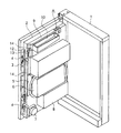
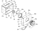
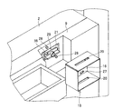
図1は、この考案の施錠装置を備えた遊技機の一例であって、遊技機としてのパチンコ機の前面枠を本体枠に対し開放した状態を示す概略斜視図である。図2は、この考案の施錠装置の一実施の形態を示す分解斜視説明図である。
Hereinafter, the best mode for carrying out the invention will be shown, and the invention will be described in more detail. Of course, this invention is not limited by the following forms.
FIG. 1 is a schematic perspective view showing a state in which a front frame of a pachinko machine as a gaming machine is opened with respect to a main body frame, which is an example of a gaming machine provided with the locking device of the present invention. FIG. 2 is an exploded perspective view showing an embodiment of the locking device of the present invention.
図1に示すように、本体枠1に対し前面枠2が蝶番によって水平方向に開閉可能となっており、前面枠2の自由端側の背面には、前面枠2の施錠装置3が取り付けられている。該施錠装置3の鉤部4、4が本体枠1の内側に設けられた受け金具(図示せず)と係合することで、前面枠2が本体枠1に対し施錠可能となっており、一方、キー操作により、鉤部4、4と受け金具との係合を解除して解錠することで、前面枠2が本体枠1に対し開放できるようになっている。
As shown in FIG. 1, the
前面枠2には、遊技盤5が取り付けられている。遊技盤5には、主制御基板ボックス6の他、図示していないが、可変画像表示装置、入賞装置、ランプ制御基板ボックス、音声制御基板ボックス、中継基板、接続端子板、球受け樋、賞球払出装置等が配設されている。主制御基板ボックス6内には、勝率を制御するROM、パチンコ機の遊技制御用CPU等が設けられている。球受け樋、賞球払出装置(いずれも図示せず)等は、背面側から見て右方寄りに配設されている。
前面枠2の下方には、球発射装置7、球発射装置制御基板ボックス8が配設されている。
A
A ball launcher 7 and a ball launcher control board box 8 are disposed below the
そして、遊技盤5には、裏側カバー9が蝶番(図示せず)によって水平方向に開閉可能となっている。裏側カバー9には、賞球タンク10が設けられており、前記球受け樋に賞球を供給するようになっている。図1における裏側カバー9は、可変画像表示装置、入賞装置、ランプ制御基板ボックス、音声制御基板ボックス、中継基板、接続端子板等を覆うサイズとなっている。裏側カバー9は、その上端部右方において、図2に示す施錠装置Aによって、その閉止位置で前面枠2に対して施錠されている。施錠装置Aの施錠・解錠は、キー操作によって行われる。裏側カバー9の自由端側の平坦板部12は、逆L字状の裏側カバー押さえ板13によって係止されている。裏側カバー押さえ板13を、図1の状態から時計方向に90゜回動させることで、裏側カバー9の押さえが解除されるようになっている。また、裏側カバー9の自由端側の上下位置には、前面枠2に係着するための係着具14、14が設けられている。係着具14としては、例えば、ナイラッチ(登録商標)が採用できる。このような係着具14を用いると、裏側カバー9を開放するのに手間がかかることから、不正操作防止にとって有効となる。なお、図1の主制御基板ボックス6は、図示していないが裏側カバー9が開放されない限り、開くことができない構造となっている。そのような構造としては、例えば、裏側カバー9に突起を、主制御基板ボックス6側に凹部を設け、裏側カバー9が閉止された時、突起と凹部が係合するようにしたものが採用できる。裏側カバー9には、図示していないが、放熱用に通風孔が形成されている。
And in the
施錠装置Aは、裏側カバー9をその閉止位置で開くことができないように施錠するものであって、施錠装置Aによって、少なくとも裏側カバー9に覆われた可変画像表示装置、入賞装置、ランプ制御基板ボックス、音声制御基板ボックス、中継基板、接続端子板等への不正操作が防止されることになる。
The locking device A locks the
施錠装置Aは、図2、図3に示されているように、概略、底壁部材16とこれに直交する4つの側壁部材17a、17b、17c、17dを有し、側壁部材17a、17b、17c、17dの後端縁が開口部となるケース本体18と、ケース本体18の開口部を塞ぐ蓋体19とからなり、ケース本体18の開口部を形成する対向する一対の平行な側壁部材17a、17cに掛け金25との掛合用スリット20、20がそれぞれ穿設され、底壁部材16には、遊技機の前面枠の裏側に設けられた裏側カバー押さえ止め具21(図4参照)の挿通用孔22が穿設されており、蓋体19の錠取着用板部23に取着されたシリンダー錠24の錠軸24aが蓋体19の内側に突出し、錠軸24aに掛け金25が固定されてなる構造である。ケース本体18に蓋体19を被せ、シリンダー錠24のキー溝24bにキー26を挿入し、キー操作して、錠軸24aを施錠位置まで回動させ、掛け金25を掛合用スリット20、20に掛合させ、キー26をシリンダー錠24から抜き取ることで、蓋体19をケース本体18に取り付けることができるようになっている。蓋体19をケース本体18から取り外すには、シリンダー錠24のキー溝24bにキー26を挿入し、キー操作して、錠軸24aを解錠位置まで回動させ、掛け金25と掛合用スリット20、20との掛合を解除すればよい。
As shown in FIGS. 2 and 3, the locking device A generally includes a
ケース本体18は、一枚の金属板を折り曲げ加工して形成されたものとして示されているが、底壁部材16、側壁部材17a、17b、17c、17dを溶接して形成してもよい。底壁部材16から各側壁部材17a、17b、17c、17dの後端縁までの前後幅は同一で、ケース本体18は、各側壁部材の後端縁が開口された直方体状となっている。ケース本体18のサイズは、裏側カバー押さえ止め具21をケース本体18の底壁部材16側から収納して、裏側カバー押さえ止め具21を前面枠に設けられた支軸を中心に回動することができ、しかも、蓋体19を被せた時に、掛け金25をケース本体18内で錠軸24aを中心に回動させ、ケース本体18の掛合用スリット20、20に掛合させて、蓋体19をロックするのに支障がないように設定されている。側壁部材17a、17cの掛合用スリット20、20は、底壁部材16内側から等距離の位置に形成されており、掛合用スリット20、20の幅は掛け金25の厚さよりも稍大きく、その長さは、蓋体19を被せてシリンダー錠24の掛け金25がケース本体18内で錠軸24aを中心に回動するのに支障がないように設定されている。
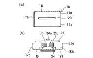
底壁部材16には、遊技機の前面枠9の裏側に設けられた裏側カバー押さえ止め具21の挿通用孔22の上下斜め位置に長円状の孔27、27が穿設されている。この長円状の孔27、27に、裏側カバーに後方に向けて突設された突起28、28(図4参照)が遊嵌されることで、ケース本体18を裏側カバー9に位置決めして止着できることになる。ケース本体18の裏側カバー9への止着により、突起28、28は、底壁部材16から後方に突出し、裏側カバー押さえ止め具21を支軸29(図4参照)を中心に回動できる範囲を設定するストッパーとして機能する。なお、図3(a)は、ケース本体18の上面側の側壁部材17aを除去した状態の平面図である。
Although the
The
蓋体19は、一枚の金属板を折り曲げ加工して形成されたものとして示されているが、錠取着用板部23、側壁板部32a、32b、32c、32dを溶接して形成してもよい。錠取着用板部23は、ケース本体18の開口部を塞ぐことができるサイズとなっている。錠取着用板部23には、錠挿通用孔33が穿設されており、シリンダー錠24の錠取着用板部23への取着は、シリンダー錠24を錠挿通用孔33に錠軸24aを先にして挿通し、蓋体19の内側に出た筒部24cの外周に形成されたネジ山に取付ナット34を螺合することで行われる。
The
シリンダー錠24の錠軸24aには、板状の掛け金25が、その中央の嵌合孔25aで嵌め合わされ、止め輪35によって固定されている。掛け金25には、突起25bが形成されており、シリンダー錠24の後端面側に設けられた回動規制ストッパー24dに当接して、錠軸24aを中心とする回動角度が規制され、施錠位置と解錠位置との間で回動可能とされている。掛け金25の回動角度は、横方向を向いた解錠角度位置と、縦方向を向いた施錠角度位置との間のほぼ90゜に設定されており、キー26をシリンダー錠24のキー溝24bに挿入し、キー26の施錠・解錠操作により、掛け金25が回動し、ケース本体18の上下の側壁板部17a、17cに設けられた掛合用スリット20、20より外に出没可能となっている。なお、図3(b)は、蓋体19の上面側の側壁板部32aを除去した状態の平面図である。
A plate-
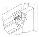
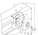
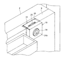
図4は、施錠装置Aが未装着であって、前面枠2に対し裏側カバー9が閉止された状態を示す部分拡大斜視図である。
前面枠2に対し裏側カバー9が閉止された状態において、裏側カバー9の凹状段部36の底部36aに形成された挿通用孔37を通って、前面枠2から後方に延設された支軸29を中心に回動可能とされた裏側カバー押さえ止め具21と、該裏側カバー押さえ止め具21の時計方向への回動を阻止する回動阻止板38とが凹状段部36の内側へ突出している。裏側カバー押さえ止め具21は、前面枠2から後方に突出した支軸29にネジ39で止められている。裏側カバー押さえ止め具21は、押さえ部21aと取手部21bが設けられたバタフライ状をしており、取手部の右側をやや重くして裏側カバー押さえ止め具21の左右のバランスを意識的に崩しておくことで、支軸29を中心に自然と時計方向に回動し、取手部の左側が回動阻止板38に当接するようになっている。このため、前面枠2に対し裏側カバー9を閉める際、裏側カバー押さえ止め具21が裏側カバー9の挿通用孔37にスムーズに通過することになる。図5は、前面枠2に対し裏側カバー9が閉止された状態を示す背面側から見た正面図である。そして、図5において、裏側カバー押さえ止め具21の取手部21bを手で持って、前面枠2の支軸29を中心に反時計方向に約90゜回動すれば、前面枠2に対し裏側カバー9を開くことができなくなる(図5の2点鎖線参照)。裏側カバー9の突起28、28は、挿通用孔37の上下斜めで支軸29に対し点対称の位置に後方に向けて突設されている。この突起28、28は、裏側カバー押さえ止め具21の支軸29を中心とする反時計方向のそれ以上の回動を規制するストッパーとして機能するとともに、ケース本体18を裏側カバー9の凹状段部36に装着する際の位置決めとして機能することから、かかる機能を果たす長さとなっている。
FIG. 4 is a partially enlarged perspective view showing a state where the locking device A is not attached and the
In a state where the
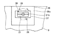
そして、図4に示すような前面枠2に対し、裏側カバー9が閉止され、裏側カバー押さえ止め具21と、回動阻止板38とが凹状段部36の内側へ突出した状態において、図6に示すように、ケース本体18の底壁部材16を裏側カバー9の凹状段部36に向け、裏側カバー押さえ止め具21と、回動阻止板38を底壁部材16の挿通用孔22に挿通させるとともに、裏側カバー9に突設された突起28、28を底壁部材16の孔27、27に遊嵌させ、凹状段部36の底部36aにケース本体18の底壁部材16を当接させる。図7は、裏側カバー9の凹状段部36の底部36aにケース本体18の底壁部材16が当接した状態を示す。そして、支軸29を中心に、裏側カバー押さえ止め具21を反時計方向に回動させ、ケース本体18を裏側カバー9を介して、前面枠2に止着する(図7の2点鎖線参照)。図8は、ケース本体18が裏側カバー9を介して前面枠2止着された状態を示す。
In the state where the
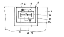
次いで、ケース本体18の開口部を蓋体19で覆い、シリンダー錠24のキー溝24bにキー26を挿入し、キー26を施錠方向(反時計方向)に回動させると、掛け金25がシリンダー錠24の錠軸24aを中心に回動し、ケース本体18の掛合用スリット20、20に掛合し、蓋体19とケース本体18が施錠される(図9参照)。
その結果、裏側カバー押さえ止め具21は、ケース本体18と蓋体19で囲まれたことになり、裏側カバー押さえ止め具21にアクセスすることができない。そのため、遊技機の背面に配設された機器や部品への不正操作は、例え、前面枠2の施錠装置を不正に解錠し、前面枠2を開くことができたとしても、合い鍵等を入手して、シリンダー錠24の解錠操作を行なって、蓋体19をケース本体18から取り外し、さらに、裏側カバー押さえ止め具21を支軸を中心に止着位置からケース本体18の挿通用孔22と合致する位置にまで回動し、裏側カバー9を開かないかぎり行うことができないことになる。この施錠装置Aを装着することで、裏側カバーの内側に配設された機器や部品への不正操作を防止できることになり、安全性が高い。
Next, the opening of the
As a result, the back-
そして、不正操作を行うには、合い鍵等によるシリンダー錠24の解錠を行わない限りは、施錠装置Aを破壊するか、または、裏側カバー9を破壊することにより行うしかなく、このような場合は、不正操作が行われたことが容易に発見できる。
In order to perform an unauthorized operation, unless the
遊技機の検査時や故障時の部品の交換等の際には、施錠状態において、キー26によりシリンダー錠24を解錠操作することで、ケース本体18の掛合用スリット20、20と掛け金25との掛合を解除し、蓋体19をケース本体18から取り外す。次いで、裏側カバー押さえ止め具21を、支軸を中心にケース本体の挿通用孔と合致する位置にまで回動させ、ケース本体18を取り外す。そして、裏側カバー押さえ板13を、図1の状態から時計方向に90゜回動し、裏側カバー9の押さえを解除させるとともに、係着具14、14を後方に引っ張って前面枠2との係着を解除し、裏側カバーを開放する。裏側カバー9が開かれた状態において、必要な検査、故障した部品の交換等を行えばよい。
When inspecting the gaming machine or replacing parts in the event of a failure, the
この施錠装置による裏側カバー9の施錠、解錠操作は、ケース本体18と蓋体19との施錠、解錠をシリンダー錠24のキー操作で行うことと、裏側カバー押さえ止め具21を支軸を中心に、ケース本体18の挿通用孔と合致する位置と止着位置との間で回動操作するといった単純な操作によって行うことができることから、熟練を要しない。
この施錠装置は、コンパクトであって場所を取らず、遊技機の背面での占有面積等も僅かでよい。また、この施錠装置は、例えば、前面枠と裏カバーを裏側カバー押さえ止め具21によって押さえ止めするようにした既存の遊技機を特に改造することなく、そのままの遊技機に装着することができ、不正操作に対し安全性の高い遊技機を安価に提供することができることになる。
The locking and unlocking operation of the
This locking device is compact, does not take up space, and may occupy a small area or the like on the back of the gaming machine. In addition, this locking device can be mounted on an existing gaming machine as it is, for example, without modifying the existing gaming machine in which the front frame and the back cover are held down by the back side
図1に示す施錠装置においては、ケース本体、蓋体を金属としたが、これに限られず、プラスチックを使用してもよく、その場合は、射出成形等によってケース本体、蓋体を製造すればよい。
また、シリンダー錠も前述したものに限られず、各種のものが採用できる。例えば、シリンダー錠として、施錠時のキー操作角度では、キーをキー溝から抜き取ることができるが、解錠時のキー操作角度では、キーをキー溝から抜き取ることができないものであってもよい。このようなシリンダー錠では、施錠時以外は、蓋体にキーが付けられたままであることから、施錠状態か解錠状態かの確認が容易である。
In the locking device shown in FIG. 1, the case main body and the lid are made of metal. However, the present invention is not limited to this, and plastic may be used. In that case, if the case main body and the lid are manufactured by injection molding or the like, Good.
Further, the cylinder lock is not limited to those described above, and various types can be adopted. For example, as a cylinder lock, the key can be extracted from the key groove at the key operation angle at the time of locking, but the key cannot be extracted from the key groove at the key operation angle at the time of unlocking. In such a cylinder lock, since the key remains attached to the lid body except during locking, it is easy to check whether the locked state or the unlocked state.
施錠装置Aによって施錠される裏側カバーは、図1に示されたカバー範囲のものに限られず、主制御基板ボックスをも覆う裏側カバーであってもよい。逆に、裏側カバーは、図1に示されたカバー範囲よりも狭いものであってもよい。この場合は、施錠装置Aの設置位置を変更すればよい。 The back side cover locked by the locking device A is not limited to the cover range shown in FIG. 1 and may be a back side cover that also covers the main control board box. Conversely, the back cover may be narrower than the cover range shown in FIG. In this case, the installation position of the locking device A may be changed.
図1においては、施錠装置によって施錠する裏側カバーを、蝶番で水平方向に回動可能としたものとして説明したが、これに限られず、例えば、裏側カバーを遊技盤5から完全に取り外すようにした着脱構造であってもよい。
In FIG. 1, the back side cover locked by the locking device has been described as being pivotable in the horizontal direction with a hinge. However, the present invention is not limited to this. For example, the back side cover is completely removed from the
また、図1において、遊技盤に主制御基板ボックス、可変画像表示装置、入賞装置、ランプ制御基板ボックス、音声制御基板ボックス、中継基板等を配設したものとして説明したが、これに限られず、例えば、遊技盤に蝶番によって水平方向に回動可能な制御支持盤を設け、該制御支持盤に主制御基板ボックス、入賞装置、ランプ制御基板ボックス、音声制御基板ボックス、中継基板等を配設するようにしたものであってもよい。 In FIG. 1, the game board is described as having a main control board box, a variable image display device, a winning device, a lamp control board box, a voice control board box, a relay board, etc., but is not limited thereto. For example, a game support board is provided with a control support board that can be rotated in the horizontal direction by a hinge, and a main control board box, a winning device, a lamp control board box, a voice control board box, a relay board, etc. are provided on the control support board. It may be as described above.
また、図1において、裏側カバーに賞球タンクを設けたものとして説明したが、これに限られず、例えば、遊技盤または前面枠に蝶番によって水平方向に回動可能とした機構板を設け、機構板に賞球タンク、球受け樋等を配設するようにしたものを用いてもよい。 Further, in FIG. 1, the description has been given on the assumption that the back cover is provided with a prize ball tank. However, the present invention is not limited to this. For example, a mechanism board that can be rotated horizontally by a hinge on a game board or a front frame is provided. You may use what made the board arrange | position a prize ball tank, a ball receiving bowl, etc. on a board.
また、この考案の施錠装置は、図2等に記載した構造に限定されるものではなく、種々の構造が採用可能である。 Moreover, the locking device of this invention is not limited to the structure described in FIG. 2 etc., A various structure is employable.
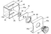
図10は、この発明の施錠装置の他の形態を示す分解斜視説明図である。
この施錠装置Bは、蓋体40の左右の側壁板部を省略したものである。ケース本体41の左右の側壁部材42、42には、蓋体40の左右への移動を防止するストッパー42a、42aを設け、蓋体40の錠取着用板部43の左右の側縁に、前記ストッパー42a、42aと係合する切欠43a、43aを設けたものとなっている。その他は、図2に示す施錠装置と同様なことから、同一番号を付し、詳細な説明は省略する。
FIG. 10 is an exploded perspective view showing another embodiment of the locking device of the present invention.
In this locking device B, the left and right side wall plate portions of the
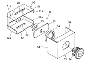
図11は、この発明の施錠装置のさらに他の形態を示す分解斜視説明図である。
この施錠装置Cは、ケース本体50の上面の側壁部材51の左右の端縁からそれぞれ下方に向かうフランジ51a、51aを設け、下面の側壁部材52の左右の端縁からそれぞれ上方に向かうフランジ52a、52aを設け、蓋体53の左右の側壁板部54、54を延長したものである。その他は、図2に示す施錠装置と同様なことから、同一番号を付し、詳細な説明は省略する。
FIG. 11 is an exploded perspective view showing still another embodiment of the locking device of the present invention.
This locking device C is provided with
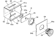
図12は、この発明の施錠装置のさらに他の形態を示す分解斜視説明図である。
この施錠装置Dは、ケース本体60の上面の側壁部材61の後端縁から上方に向け断面逆L字状にフランジ61aを、下面の側壁部材62の後端縁から下方に向け断面L字状にフランジ62aを設け、左右の側壁部材63、63には、蓋体64の左右への移動を防止するストッパー63a、63aを設け、蓋体64は、錠取着用板だけとし、その左右の側縁に、前記ストッパー63a、63aと係合する切欠64a、64aを設けたものとなっている。その他は、図2に示す施錠装置と同様なことから、同一番号を付し、詳細な説明は省略する。
FIG. 12 is an exploded perspective view showing still another embodiment of the locking device of the present invention.
The locking device D includes a
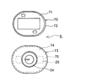
図13は、この発明の施錠装置のさらに他の形態を示す正面図である。
この施錠装置Eは、ケース本体70を、長円状の底壁部材71に筒状側壁部材72が形成された筒状体とし、蓋体73を、長円状の錠取着用板部74に筒状側壁板部75が形成された筒状体としたものである。その他は、図2に示す施錠装置と同様なことから、同一番号を付し、詳細な説明は省略する。
この施錠装置Eは、遊技機の裏側カバーの凹状段部が長円状となっているか、または、凹状段部のない平面部となっているものに使用すればよい。
FIG. 13 is a front view showing still another embodiment of the locking device of the present invention.
In this locking device E, the case
This locking device E may be used in a case where the concave step portion of the back cover of the gaming machine has an oval shape or a flat portion without the concave step portion.
そして、この考案の施錠装置は、図1に示した構造のパチンコ機に限られず各種の構造のパチンコ機に使用することができることはもちろん、パチンコ機以外の各種の遊技機に使用することができる。 The locking device of the present invention is not limited to the pachinko machine having the structure shown in FIG. 1 and can be used for various pachinko machines having various structures, as well as various game machines other than the pachinko machine. .
A 施錠装置
2 前面枠
9 裏側カバー
18 ケース本体
19 蓋体
20 掛合用スリット
21 裏側カバー押さえ止め具
22 挿通用孔
24 シリンダー錠
25 掛け金
A
Claims (5)
底壁部材とこれに直交する側壁部材を有するケース本体と、該ケース本体の蓋体とからなり、
前記ケース本体の側壁部材には一対の掛け金との掛合用スリットが対向して穿設され、底壁部材には、遊技機の前面枠の裏側に回動可能に軸支された裏側カバー押さえ止め具を挿通する挿通用孔が穿設されており、
前記蓋体の内側に、蓋体の錠取着用板部に取着されたシリンダー錠の錠軸が突出し、該錠軸に掛け金が固定されてなることを特徴とする遊技機の裏側カバーの施錠装置。 A locking device that locks the back cover disposed on the back side of the front frame of the gaming machine,
A case main body having a bottom wall member and a side wall member orthogonal to the bottom wall member, and a lid of the case main body,
The side wall member of the case body is formed with a slit for engaging with a pair of latches, and the bottom wall member has a back side cover presser that is pivotally supported on the back side of the front frame of the gaming machine. There is a hole for inserting the tool,
Locking the back cover of a gaming machine, wherein a lock shaft of a cylinder lock attached to a lock mounting plate portion of the cover body protrudes inside the cover body, and a latch is fixed to the lock shaft. apparatus.
5. The locking device for a back cover of a gaming machine according to claim 1, wherein the case main body is set to a size that can be attached to a concave step formed in the back cover.
Priority Applications (1)
| Application Number | Priority Date | Filing Date | Title |
|---|---|---|---|
| JP2005002381U JP3111663U (en) | 2005-04-15 | 2005-04-15 | Locking device for back cover of gaming machine |
Applications Claiming Priority (1)
| Application Number | Priority Date | Filing Date | Title |
|---|---|---|---|
| JP2005002381U JP3111663U (en) | 2005-04-15 | 2005-04-15 | Locking device for back cover of gaming machine |
Publications (1)
| Publication Number | Publication Date |
|---|---|
| JP3111663U true JP3111663U (en) | 2005-07-28 |
Family
ID=43274128
Family Applications (1)
| Application Number | Title | Priority Date | Filing Date |
|---|---|---|---|
| JP2005002381U Expired - Lifetime JP3111663U (en) | 2005-04-15 | 2005-04-15 | Locking device for back cover of gaming machine |
Country Status (1)
| Country | Link |
|---|---|
| JP (1) | JP3111663U (en) |
-
2005
- 2005-04-15 JP JP2005002381U patent/JP3111663U/en not_active Expired - Lifetime
Similar Documents
| Publication | Publication Date | Title |
|---|---|---|
| JP4014755B2 (en) | Pachinko machine | |
| JP4292307B2 (en) | Game machine | |
| JP4431209B2 (en) | Game machine | |
| JP4125546B2 (en) | Mechanism for preventing unauthorized opening of circuit board case | |
| JP2004073512A (en) | Seal structure | |
| JPH10328385A (en) | Control substrate housing case for game machine | |
| JP4210766B2 (en) | Game machine | |
| JPH11300004A (en) | Base plate case | |
| JP3111663U (en) | Locking device for back cover of gaming machine | |
| JP5467450B2 (en) | Sealing structure of control board | |
| JP2004097525A (en) | Game machine board box | |
| JP2002172243A (en) | Closure structure of circuit board in gaming machine | |
| JPH09253300A (en) | Sealing structure of substrate housing box for pachinko machine | |
| JPH06319850A (en) | Fixed structure of game circuit board case | |
| JP4210765B2 (en) | Game machine | |
| JP2009189632A (en) | Board case and board attachment device | |
| JPH10225560A (en) | Circuit board mounting structure for gaming machines | |
| JP2004049469A (en) | Sealing device for control board case of game machine | |
| JP2000350844A (en) | Attaching structure for pc board box of game machine | |
| JP4401426B1 (en) | Board case and gaming machine | |
| JP2003175249A (en) | Game machine | |
| JP2003305257A (en) | Board box for game machine | |
| JP4338212B2 (en) | Board case and board mounting apparatus | |
| JP2004008580A (en) | Sealing device of control board case for game machine | |
| JP2009183681A (en) | Board mounting device |
Legal Events
| Date | Code | Title | Description |
|---|---|---|---|
| R150 | Certificate of patent or registration of utility model |
Free format text: JAPANESE INTERMEDIATE CODE: R150 |
|
| FPAY | Renewal fee payment (event date is renewal date of database) |
Free format text: PAYMENT UNTIL: 20110608 Year of fee payment: 6 |
|
| FPAY | Renewal fee payment (event date is renewal date of database) |
Free format text: PAYMENT UNTIL: 20150608 Year of fee payment: 10 |
|
| EXPY | Cancellation because of completion of term |