JP2004008580A - Sealing device of control board case for game machine - Google Patents
Sealing device of control board case for game machine Download PDFInfo
- Publication number
- JP2004008580A JP2004008580A JP2002167748A JP2002167748A JP2004008580A JP 2004008580 A JP2004008580 A JP 2004008580A JP 2002167748 A JP2002167748 A JP 2002167748A JP 2002167748 A JP2002167748 A JP 2002167748A JP 2004008580 A JP2004008580 A JP 2004008580A
- Authority
- JP
- Japan
- Prior art keywords
- board case
- base
- engaging
- cover
- control board
- Prior art date
- Legal status (The legal status is an assumption and is not a legal conclusion. Google has not performed a legal analysis and makes no representation as to the accuracy of the status listed.)
- Pending
Links
Images


Landscapes
- Slot Machines And Peripheral Devices (AREA)
Abstract
Description
【0001】
【発明の属する技術分野】
この発明は、ベースとカバーとに分割され遊技機筐体に固定される基板ケースに設けられ、遊技機用の制御基板を基板ケース内に収容した状態で基板ケースを封印する遊技機用制御基板ケースの封印装置に関する。
【0002】
【従来の技術】
一般に、スロットマシンやパチンコ機等の遊技機は、マイクロコンピュータにより制御されるようになっており、このマイクロコンピュータは予め所定パターンのプリント配線が施された制御基板上に、CPUやROM、RAM等のチップ部品が実装されて構成され、この制御基板が、図4に示すような基板ケース100内に収容されて遊技機筐体内の所定位置に配設される。
【0003】
ところで、この基板ケース100は、図4に示すように、透明樹脂製のベース101とカバー102とに分割され、ケース100内に制御基板を収めた後、かしめ部103においてベース101とカバー102とをかしめて封印し、このかしめ部103を壊さない限りケース100を開けることができない構造になっている。ここで、図4には示されていないホルダが遊技機筐体内部の所定位置に固着され、ケース100のベース101はこのホルダを介して遊技機筐体に固定されている。
【0004】
そして、かしめ部103は、図4に示すように、例えばケース100の右側面に設けられた6個の封印部材104〜109を備え、更にこれら各封印部材104〜109は、カバー102の右側面に一体的に形成されたほぼ円筒状を成すカバー側封印部104a〜109aと、ベース101の右側面であって各カバー側封印部104a〜109aそれぞれとの対向位置に一体的に形成されたベース側封印部104b〜109bとを備え、ねじにより各カバー側封印部104a〜109aそれぞれと各ベース側封印部104b〜109bそれぞれとが締結されて封印されるようになっている。但し、図4において、110,111,112はカバー102に形成された透孔から導出されたピンヘッダであり、ケース100内の制御基板に配設されており、外部ケーブルに接続される。
【0005】
このとき、当初内蔵されている正規のROMを取り外して不正な変造ROMが取り付けられることを防止するために、まず1番目の封印部材104の両封印部104a,104bがねじ止めされてケース100が封印され、この封印状態のまま制御基板がケース100ごとパチンコホールに搬送される。更に、パチンコホールにおいて、2番目の両封印部105a,105bがねじ止めされて封印状態のケース100がホルダを介して遊技機筐体に固定される。
【0006】
そして、監督機関が変造ROMを取り締まるために、パチンコホールにおいてチェックする際に、ねじ止めされている1番目及び2番目の封印部材104,105が切断されて封印解除され、チェック終了後に3番目の封印部材106の両封印部106a,106bがねじ止めされ、このような監督機関による変造ROMの取り締まりごとに4番目、5番目の封印部材107,108が順次ねじ止めされて封印され、合計3回の監督機関によるチェックまで許容される構造になっている。
【0007】
尚、制御基板をケース100ごと回収する際に、5番目の封印部材108が切断されてケース100が遊技機筐体から取り外し可能な状態にされると共に、6番目の封印部材109がねじ止めされてケース100が封印状態のまま搬送可能な状態にされ、制御基板がケース100ごと回収される。
【0008】
【発明が解決しようとする課題】
しかし、上記したような従来のかしめ部103は、ねじ止めによって封印するものであるため、ねじ頭に形成されているマイナスドライバの係合溝を、逆動できないような傾斜構造にしてあるものの、円筒状のカバー側封印部104a〜109aに外部から工具を挿入して締結状態のねじを逆動操作して緩めることが可能であり、制御基板に対して何らかの不正行為を施すことができ、いわゆるゴト行為を防止することができないおそれがあった。
【0009】
しかも、遊技機筐体に固定されたケース100に対し、正面側からねじ止めする構造であるため、ねじ止め後において外部から見えるのはねじ頭だけであり、ねじが緩められる等の不正が行われても不正の痕跡を外部からはっきりと視認することができず、不正行為を確実に排除することが困難であった。
【0010】
そこで、本発明は、制御基板を収容する基板ケースの封印部分に対して、外部から工具により操作できず、不正の痕跡を外部からはっきりと視認可能な構造にし、不正行為を確実に防止できるようにすることを目的とする。
【0011】
【課題を解決するための手段】
上記した目的を達成するために、本発明は、ベースとカバーとに分割され遊技機筐体に固定される基板ケースに設けられ、遊技機用の制御基板を前記基板ケース内に収容した状態で前記基板ケースを封印する遊技機用制御基板ケースの封印装置において、前記カバーの少なくともその1つの側壁が前記ベースの1つの側壁の外方に位置するように前記カバーが形成され、前記カバーの前記側壁に透設された嵌入孔と、前記ベースの前記側壁に透設された係合孔と、前記嵌入孔に挿入されて根元部分が前記嵌入孔に嵌入すると共に先端部分が前記係合孔に嵌入する係合体とを備えていることを特徴としている(請求項1)。
【0012】
このような構成によれば、係合体が水平方向から嵌入孔及び係合孔に挿入、嵌入されることにより、係合体によってベースとカバーとが係合されるため、ねじを用いることなくケースを封印することができ、係合体の状態を目視できるようにケースを透明にしておくことで、不正があったときは不正の痕跡を外部から早期に発見することができる。
【0013】
また、本発明は、前記嵌入孔に嵌入した状態における前記係合体の端面が前記カバーの前記側壁の外側面とほぼ同一面を成すことを特徴としている(請求項2)。このような構成によれば、係合体を嵌入孔及び係合孔に挿入、嵌入したときに、係合体の端面がカバーの側壁の外側面とほぼ同一面を成すため、係合体の端面を工具により細工して係合体を外部から引き抜くことが困難になり、不正行為を確実に防止することができる。
【0014】
また、本発明は、前記係合体を途中で切断するための開口が前記カバーに形成されていることを特徴としている(請求項3)。このような構成によれば、封印を解除する必要が生じた場合に、この開口を介して係合体の途中を切断することができる。
【0015】
また、本発明は、前記ベースの前記係合孔の内側に形成された透視可能な密閉室を備え、前記密閉室は、切断後押し込まれた前記係合体の先端部分を収容するものであることを特徴としている(請求項4)。このような構成によれば、係合体が途中で切断されたときに、係合体の先端部分を密閉室内に押し込んで収容しておき、密閉室内を外部から監視して密閉室内に収容されている係合体の先端部分を見ることで、不正行為の有無を容易に判断することができ、係合体を切断した痕跡を明確に把握することができ、不正に係合体を切断した場合にこれを容易に発見することができる。
【0016】
また、本発明は、前記係合体が、可撓性連結部材を介して前記ベースまたは前記カバーのいずれかに連結されていることを特徴としている(請求項5)。このような構成によれば、係合体がベースまたはカバーに連結されているため、封印作業時に係合体を紛失するおそれがなく、封印作業を非常に効率よく行うことができる。
【0017】
また、本発明は、前記係合体が、前記嵌入孔に嵌入する嵌入部と、前記係合孔に嵌入する頭部と、前記嵌入部と前記頭部とを繋ぐ接続部と、前記頭部に形成され前記頭部の前記係合孔への嵌入時に前記ベースの前記側壁内面に係止して前記係合体の引き抜きを阻止する係止部とを備えていることを特徴としている(請求項6)。
【0018】
このような構成によれば、係合体の頭部がベース側の係合孔に嵌入した状態では、係止部がベースの側壁内面に係止して引き抜きが阻止されるため、工具による不正行為をより確実に防止することができる。
【0019】
また、本発明は、前記嵌入孔、前記係合孔及び前記係合体が各々複数個設けられていることを特徴としている(請求項7)。このような構成によれば、例えば制御基板のチェックのためにカバーを開放する必要が生じても、係合体を順次嵌入孔及び係合孔に挿入して嵌入すればよく、封印解除及び封印を簡単に繰り返すことができる。
【0020】
【発明の実施の形態】
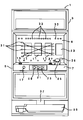
この発明を遊技機であるスロットマシンに適用した場合における第1実施形態について図1ないし図3を参照して説明する。但し、図1はスロットマシンの正面図、図2はケースの一部の分解斜視図、図3は組立状態における一部の斜視図である。
【0021】
本実施形態におけるスロットマシンは、例えば図1に示すように構成されている。即ち、図1に示すように、スロットマシン1では、筐体3の前面が前面パネル5により開閉自在に閉塞され、この前面パネル5のほぼ中央高さの位置に操作板7が配設されると共に、この操作板7の上方に正面板9が配設されている。
【0022】
そして、この正面板9には3個のリール窓11が並設され、各リール窓11の内側には左、中、右の各リールが配置され、右端のリール窓11の横には、ゲームの演出用画面を表示する液晶ディスプレイ13が配設されており、各リール窓11からは、各リールの図柄が各々3個ずつ見えるように設定されている。
【0023】
更に、この操作板7には、クレジットされているメダルから投入を行うクレジットメダルボタン15、各リールの回転を開始させるためのスタートレバー17、第1ないし第3ストップボタン19,21,23、及び、メダル投入口25や払出しボタン27が設けられている。また、正面板9には入賞ラインが描かれると共に、入賞ライン中の有効ラインを表示する有効表示ランプ31、ボーナスゲームの状態などを表示する種々の演出表示ランプ33、クレジットメダルの枚数を表示するメダル枚数表示器35が正面板9に配設され、操作板7の下方にはメダル払出口37やメダル受け39が設けられている。
【0024】
ところで、筐体3内部の上側には、CPUやROM、RAM等のチップ部品が実装された制御基板を収容した基板ケースが配設される。図2及び図3に示すように、この基板ケース41は、透明樹脂製のベース43とカバー45とに分割され、基板ケース41内に制御基板が収められた後、右側のかしめ部49においてベース43とカバー45とがかしめられて封印され、筐体3内部に固着されたホルダにベース基板ケース41が固定され、かしめ部49を壊さない限り基板ケース41を開けることができない構造になっている。このとき、カバー45の右側壁がベース43の右側壁の外方に位置するように、カバー45及びベース43の寸法設定が成されている。また、ホルダに基板ケース41を固定する固定手段は、図2,3には示されていないが、かしめ部49とは別に設けられている。
【0025】
ところで、かしめ部49は、カバー45の右側壁に透設された嵌入孔51と、ベース43の右側壁に透設された係合孔53と、嵌入孔51に嵌挿されて先端が係合孔53に嵌入する係合体55とを備え、嵌入孔51、係合孔53及び係合体55が複数個(ここでは、5個)ずつ設けられている。これら嵌入孔51は、内径の異なる2段の円形孔が連続的に形成された横断面凸字状を成しており、係合孔53は、嵌入孔51の小径部分と同じか若干小さい内径に設定されている。
【0026】
また、図2及び図3に示すように、ベース43の係合孔53の内側には密閉室57がベース43に一体的に形成され、この密閉室57を形成する壁面は基板ケース41の材質と同じであって透明であり、外部から密閉室57の内部を視認することができるようになっている。更に、カバー45の前面右端部には、係合体55を途中で切断するための矩形の開口59が複数個(ここでは、5個)形成されている。
【0027】
ところで、図2及び図3に示すように、係合体55は、嵌入部55aと、その先端の頭部55bと、これらを繋ぐ軸状の接続部55cとを備えており、嵌入部55aは嵌入孔51と同じ形状に形成されて嵌入孔51に嵌入する。そして、このように嵌入孔53と嵌入部55aとが同一形状であることから、嵌入孔53に嵌入した係合体55の嵌入部55aの端面はカバー45の右側壁の外側面とほぼ同一面を成し、基板ケース41の筐体3内での狭い配置スペースとの関係もあって、嵌入部55aの端面を工具により細工して係合体55を外部から引き抜くことができないようになっている。
【0028】
また、軸状の接続部55cの先端に、係合孔53の内径と同径に頭部55bが一体形成され、この頭部55bの先端に係合孔53の内径よりもやや大径に係止部55dが一体形成されている。この係止部55dは縦溝によって2分割されており、これにより頭部55bの係合孔53への嵌入時に、係合孔53の内径よりも大径であっても係止部55dは係合孔53を通ってベース43の右側壁内面に係止可能になっており、この係止部55dの係止によって、係合体55の引き抜きが阻止される。
【0029】
更に、図2及び図3に示すように、カバー45の右側壁にインサート成型により設けられた可撓性連結部材61を介して、係合体55の嵌入部55aがカバー45に連結されており、係合体55を嵌入孔51、係合孔53に嵌入した後、連結部材61を嵌入部55a付近で切断しておけば、係合体55を外部から引き抜くことは不可能になる。
【0030】
また、係合体55の嵌入孔51、係合孔53への嵌入後、開口59からニッパなどの切断用工具により係合体55の接続部55cが切断され、係合孔53の内側に切断後の係合体55の先端部分が押し込まれて密閉室57内に収容される。
【0031】
ところで、従来の場合と同様に、当初内蔵されている制御基板47上の正規のROMを取り外して不正な変造ROMが取り付けられることを防止するために、まず1番目の係合体55が嵌入孔51、係合孔53に挿入されて嵌入され、これによりケース41が封印され、この封印状態のまま制御基板47がケース41ごとパチンコホールに搬送される。
【0032】
更に、パチンコホールにおいて、図1〜3には示されていない固定手段により、基板ケース41が筐体3の所定位置に固着されたホルダに固定され、封印状態の基板ケース41がホルダを介して筐体3内部の所定位置に設置される。
【0033】
そして、監督機関が変造ROMを取り締まるために、パチンコホールにおいてチェックする際には、カバー45の開口59から、封印されている1番目の係合体55の接続部55cがニッパにより切断されて封印解除され、カバー45が開放可能な状態とされると共に、切断後の係合体55の先端部分が密閉室57内に押し込まれて収容される。更に、チェックが終了すると、2番目の係合体55が嵌入孔51、係合孔53に挿入されて嵌入され、以後このような監督機関による変造ROMの取り締まりごとに3番目ないし5番目の係合体55により基板ケース41が順次封印される。
【0034】
尚、制御基板を基板ケース41ごと回収する際に、5番目の係合体55により基板ケース41を封印したまま、基板ケース41が筐体3内部から取り外され、その封印状態のまま搬送されて制御基板が基板ケース41ごと回収される。
【0035】
従って、上記した実施形態によれば、係合体55を水平方向から嵌入孔51及び係合孔53に挿入して嵌入することにより、従来のように、ねじを用いることなく基板ケース41を簡単に封印することができる。
【0036】
また、係合体55の嵌入部55aの端面がカバー45の右側壁の外側面と同一面を成すため、係合体55の嵌入部55aの端面を工具により細工して係合体55を外部から引き抜くことが困難であり、不正行為を確実に防止することができる。
【0037】
しかも、筐体3の正面から基板ケース41を見たときに、嵌入孔51及び係合孔53に挿入、嵌入している係合体55をはっきりと視認することができるため、係合体55が外部から切断された場合の痕跡を明確に把握することができ、不正行為を早期に発見することができる。
【0038】
更に、係合体55を途中で切断したときに、係合体55の先端部分を透明な密閉室57内に押し込んで収容することにより、係合体55を切断した痕跡が明確になり、監督機関のチェックの回数よりも多く係合体55が不正に切断された場合にはこれを容易に発見することができる。
【0039】
なお、上記した実施形態では、係合体55をカバー45に連結した場合について説明しているが、係合体55はベース43に連結されていてもよいのは勿論である。
【0040】
また、上記した実施形態では、カバー45(またはベース43)とは別部材の可撓性連結部材61により係合体55を連結する例を挙げたが、係合体55を連結する連結部材61はカバー45(またはベース43)に一体成型により形成されていても構わない。こうすれば、連結部材61の複製が困難になって、不正をより確実に防止できる。更には、係合体55は必ずしも連結部材61により連結しておく必要はなく、係合体55は、ベース43やカバー45とは別個の独立した部材であってもよい。また、開口59は格子状または薄膜状としてもよい。
【0041】
また、上記した実施形態では、嵌入孔51、係合孔53及び係合体55をそれぞれ5個としているが、これらの個数は特に5個に限定されるものではない。
【0042】
更に、上記した実施形態では、本発明をスロットマシンに適用した場合について説明したが、パチンコ機といった他の遊技機にも本発明を適用することができ、その場合にも上記した各実施形態と同等の効果を得ることができる。
【0043】
また、本発明は上記した実施形態に限定されるものではなく、その趣旨を逸脱しない限りにおいて上述したもの以外に種々の変更を行うことが可能である。
【0044】
【発明の効果】
以上のように、請求項1に記載の発明によれば、係合体が水平方向から嵌入孔及び係合孔に挿入、嵌入されることにより、係合体によってベースとカバーとが係合されるため、ねじを用いることなくケースを封印することができ、係合体の状態を目視できるようにケースを透明にしておくことで、不正があったときは不正の痕跡を外部から早期に発見することが可能である。
【0045】
また、請求項2に記載の発明によれば、係合体を嵌入孔及び係合孔に挿入、嵌入したときに、係合体の端面がカバーの側壁の外側面とほぼ同一面を成すため、係合体の端面を工具により細工して係合体を外部から引き抜くことが困難になり、不正行為を確実に防止することが可能になる。
【0046】
また、請求項3に記載の発明によれば、係合体が途中で切断されたときに、係合体の先端部分を密閉室内に押し込んで収容することにより、係合体を切断した痕跡が明確になり、不正に係合体を切断した場合にこれを容易に発見することが可能になる。
【0047】
また、請求項4に記載の発明によれば、係合体が途中で切断されたときに、係合体の先端部分を密閉室内に押し込んで収容しておき、密閉室内を外部から監視して密閉室内に収容されている係合体の先端部分を見ることで、不正行為の有無を容易に判断することができ、係合体を切断した痕跡を明確に把握することができ、不正に係合体を切断した場合にこれを容易に発見することが可能になる。
【0048】
また、請求項5に記載の発明によれば、係合体がベースまたはカバーに連結されているため、封印作業時に係合体を紛失するおそれがなく、封印作業を非常に効率よく行うことが可能になる。
【0049】
また、請求項6に記載の発明によれば、係止部がベースの側壁内面に係止して引き抜きが阻止されるため、工具による不正行為をより確実に防止することが可能になる。
【0050】
また、請求項7に記載の発明によれば、例えば制御基板のチェックのためにカバーを開放する必要が生じても、係合体を順次嵌入孔及び係合孔に挿入して嵌入すればよく、封印解除及び封印を簡単に繰り返すことが可能になる。
【図面の簡単な説明】
【図1】この発明の一実施形態におけるスロットマシンの正面図である。
【図2】この発明の一実施形態におけるケースの一部の分解斜視図である。
【図3】この発明の一実施形態におけるケースの組立状態の斜視図である。
【図4】従来例の斜視図である。
【符号の説明】
1 スロットマシン(遊技機)
3 筐体(遊技機筐体)
41 基板ケース
43 ベース
45 カバー
51 嵌入孔
53 係合孔
55 係合体
55a 嵌入部
55b 頭部
55c 接続部
55d 係止部
57 密閉室
59 開口
61 連結部材[0001]
TECHNICAL FIELD OF THE INVENTION
The present invention provides a control board for a gaming machine which is provided on a board case which is divided into a base and a cover and which is fixed to a gaming machine housing, and seals the board case in a state where a control board for the gaming machine is accommodated in the board case. The present invention relates to a case sealing device.
[0002]
[Prior art]
Generally, gaming machines such as slot machines and pachinko machines are controlled by a microcomputer. The microcomputer is provided with a CPU, ROM, RAM, etc., on a control board on which printed wiring of a predetermined pattern is provided in advance. The control board is accommodated in a
[0003]
By the way, as shown in FIG. 4, the
[0004]
As shown in FIG. 4, the
[0005]
At this time, in order to prevent the original built-in regular ROM from being removed and an unauthorized altered ROM from being attached, first, both sealing portions 104a and 104b of the
[0006]
When the supervisory authority checks the altered ROM in the pachinko hall, the first and
[0007]
When the control board is collected together with the
[0008]
[Problems to be solved by the invention]
However, since the above-described
[0009]
In addition, since the
[0010]
Therefore, the present invention provides a structure in which a sealed portion of a board case accommodating a control board cannot be operated by a tool from the outside, and a trace of fraud is clearly visible from the outside, so that fraud can be reliably prevented. The purpose is to.
[0011]
[Means for Solving the Problems]
In order to achieve the above object, the present invention is provided in a board case that is divided into a base and a cover and fixed to a game machine housing, and a control board for a game machine is accommodated in the board case. In a sealing device for a control board case for a game machine for sealing the board case, the cover is formed such that at least one side wall of the cover is located outside one side wall of the base, and A fitting hole penetrating through the side wall, an engaging hole penetrating through the side wall of the base, and a root portion inserted into the fitting hole so that a root portion fits into the fitting hole and a tip portion fits into the engaging hole. And an engaging body to be fitted (claim 1).
[0012]
According to such a configuration, the base and the cover are engaged by the engagement body when the engagement body is inserted and fitted into the insertion hole and the engagement hole from the horizontal direction. The case can be sealed, and the case is made transparent so that the state of the engagement body can be visually checked, so that when there is fraud, traces of fraud can be found from the outside at an early stage.
[0013]
Further, the present invention is characterized in that an end surface of the engagement body in a state of being fitted into the fitting hole forms substantially the same plane as an outer surface of the side wall of the cover (claim 2). According to such a configuration, when the engaging body is inserted into and fitted into the fitting hole and the engaging hole, the end face of the engaging body is substantially flush with the outer side surface of the side wall of the cover. This makes it difficult to pull out the engaging body from the outside by working it, and it is possible to reliably prevent fraud.
[0014]
Further, the present invention is characterized in that an opening for cutting the engaging body halfway is formed in the cover (claim 3). According to such a configuration, when it is necessary to release the seal, the middle of the engagement body can be cut through the opening.
[0015]
Further, the present invention includes a see-through sealed chamber formed inside the engaging hole of the base, and the sealed chamber accommodates a tip portion of the engaging body pushed after cutting. (Claim 4). According to such a configuration, when the engagement body is cut in the middle, the distal end portion of the engagement body is pushed into the closed chamber to be housed, and the closed chamber is monitored from the outside and housed in the closed chamber. By looking at the tip of the engagement body, it is possible to easily judge the presence or absence of fraudulent acts, and to clearly grasp the trace of cutting the engagement body. Can be found in
[0016]
Further, the present invention is characterized in that the engaging body is connected to either the base or the cover via a flexible connecting member (claim 5). According to such a configuration, since the engagement body is connected to the base or the cover, there is no risk of the engagement body being lost during the sealing operation, and the sealing operation can be performed very efficiently.
[0017]
In addition, the present invention is characterized in that the engaging body has a fitting portion fitted in the fitting hole, a head fitted in the engaging hole, a connecting portion connecting the fitted portion and the head, And a locking portion that is formed and locks to the inner surface of the side wall of the base when the head is fitted into the engagement hole to prevent the engagement body from being pulled out. ).
[0018]
According to such a configuration, in a state where the head of the engagement body is fitted into the engagement hole on the base side, the engagement portion is engaged with the inner surface of the side wall of the base and is prevented from being pulled out. Can be more reliably prevented.
[0019]
Further, the present invention is characterized in that a plurality of each of the fitting hole, the engaging hole, and the engaging body are provided (claim 7). According to such a configuration, for example, even if it becomes necessary to open the cover for checking the control board, it is only necessary to sequentially insert the engaging bodies into the fitting holes and the fitting holes and fit them. Can be easily repeated.
[0020]
BEST MODE FOR CARRYING OUT THE INVENTION
A first embodiment in which the present invention is applied to a slot machine as a game machine will be described with reference to FIGS. 1 is a front view of the slot machine, FIG. 2 is an exploded perspective view of a part of a case, and FIG. 3 is a perspective view of a part in an assembled state.
[0021]
The slot machine according to the present embodiment is configured as shown in FIG. 1, for example. That is, as shown in FIG. 1, in the
[0022]
On the
[0023]
The
[0024]
By the way, a board case that accommodates a control board on which chip components such as a CPU, a ROM, and a RAM are mounted is disposed above the inside of the
[0025]
By the way, the caulking portion 49 is inserted into the
[0026]
As shown in FIGS. 2 and 3, a sealed
[0027]
By the way, as shown in FIGS. 2 and 3, the engaging
[0028]
A
[0029]
Further, as shown in FIGS. 2 and 3, the fitting portion 55 a of the
[0030]
Further, after the
[0031]
By the way, as in the conventional case, the first
[0032]
Further, in the pachinko hall, the substrate case 41 is fixed to a holder fixed to a predetermined position of the
[0033]
Then, when the supervisory authority checks in the pachinko hall to crack down on the altered ROM, the connection portion 55c of the sealed
[0034]
When the control board is collected together with the board case 41, the board case 41 is removed from the inside of the
[0035]
Therefore, according to the above-described embodiment, the board case 41 can be easily formed without using screws as in the related art by inserting the
[0036]
Further, since the end face of the fitting portion 55a of the engaging
[0037]
Moreover, when the board case 41 is viewed from the front of the
[0038]
Furthermore, when the engaging
[0039]
Note that, in the above-described embodiment, the case where the
[0040]
Further, in the above-described embodiment, the example in which the engaging
[0041]
In the above-described embodiment, the number of the fitting holes 51, the number of the engaging
[0042]
Further, in the above-described embodiment, the case where the present invention is applied to a slot machine has been described. However, the present invention can be applied to other gaming machines such as a pachinko machine, and in that case, each of the above-described embodiments and An equivalent effect can be obtained.
[0043]
Further, the present invention is not limited to the above-described embodiment, and various changes other than those described above can be made without departing from the gist of the present invention.
[0044]
【The invention's effect】
As described above, according to the first aspect of the present invention, the base and the cover are engaged by the engaging body when the engaging body is inserted and fitted into the fitting hole and the engaging hole from the horizontal direction. The case can be sealed without using screws, and the case is made transparent so that the state of the engagement body can be visually checked, so that when there is fraud, traces of fraud can be found early from the outside. It is possible.
[0045]
According to the second aspect of the present invention, when the engaging body is inserted into and fitted into the fitting hole and the engaging hole, the end surface of the engaging body is substantially flush with the outer surface of the side wall of the cover. It becomes difficult to work out the end face of the union with a tool and pull out the engagement body from the outside, and it is possible to reliably prevent fraud.
[0046]
According to the third aspect of the present invention, when the engaging body is cut halfway, the tip of the engaging body is pushed into the closed chamber and housed, so that the trace of the cutting of the engaging body becomes clear. In the case where the engaging body has been illegally cut, this can be easily found.
[0047]
According to the fourth aspect of the present invention, when the engaging body is cut halfway, the distal end portion of the engaging body is pushed into the closed chamber to be housed, and the closed chamber is monitored from the outside to monitor the closed chamber. By observing the tip of the engaging body accommodated in the device, it is possible to easily determine the presence or absence of wrongdoing, and to clearly grasp the trace of the cutting of the engaging body, and to illegally cut the engaging body. In this case, this can be easily found.
[0048]
According to the fifth aspect of the present invention, since the engagement body is connected to the base or the cover, there is no risk of losing the engagement body during the sealing operation, and the sealing operation can be performed very efficiently. Become.
[0049]
Further, according to the invention described in
[0050]
According to the invention of
[Brief description of the drawings]
FIG. 1 is a front view of a slot machine according to an embodiment of the present invention.
FIG. 2 is an exploded perspective view of a part of a case according to the embodiment of the present invention.
FIG. 3 is a perspective view of an assembled state of the case according to the embodiment of the present invention.
FIG. 4 is a perspective view of a conventional example.
[Explanation of symbols]
1 slot machine (game machine)
3 housing (game machine housing)
41
Claims (7)
前記カバーの少なくともその1つの側壁が前記ベースの1つの側壁の外方に位置するように前記カバーが形成され、
前記カバーの前記側壁に透設された嵌入孔と、前記ベースの前記側壁に透設された係合孔と、前記嵌入孔に挿入されて根元部分が前記嵌入孔に嵌入すると共に先端部分が前記係合孔に嵌入する係合体と
を備えていることを特徴とする遊技機用制御基板ケースの封印装置。A control board case for a gaming machine, which is provided on a board case divided into a base and a cover and fixed to a gaming machine housing, and seals the board case in a state where a control board for the gaming machine is accommodated in the board case. In the sealing device,
The cover is formed such that at least one side wall of the cover is located outside one side wall of the base;
A fitting hole penetrated through the side wall of the cover, an engaging hole penetrating through the side wall of the base, and a base portion inserted into the fitting hole, the root portion of which fits into the fitting hole, and the tip portion is A sealing device for a control board case for a gaming machine, comprising: an engagement body fitted into an engagement hole.
前記嵌入孔に嵌入する嵌入部と、前記係合孔に嵌入する頭部と、前記嵌入部と前記頭部とを繋ぐ接続部と、前記頭部に形成され前記頭部の前記係合孔への嵌入時に前記ベースの前記側壁内面に係止して前記係合体の引き抜きを阻止する係止部とを備えていることを特徴とする請求項1ないし5のいずれかに記載の遊技機用制御基板ケースの封印装置。The engagement body,
A fitting portion that fits into the fitting hole, a head that fits into the engaging hole, a connecting portion that connects the fitting portion and the head, and a fitting portion that is formed in the head and that engages with the engaging hole of the head. 6. A control for a gaming machine according to claim 1, further comprising: a locking portion which locks to the inner surface of the side wall of the base when the base is fitted to prevent the engaging body from being pulled out. Board case sealing device.
Priority Applications (1)
| Application Number | Priority Date | Filing Date | Title |
|---|---|---|---|
| JP2002167748A JP2004008580A (en) | 2002-06-07 | 2002-06-07 | Sealing device of control board case for game machine |
Applications Claiming Priority (1)
| Application Number | Priority Date | Filing Date | Title |
|---|---|---|---|
| JP2002167748A JP2004008580A (en) | 2002-06-07 | 2002-06-07 | Sealing device of control board case for game machine |
Publications (2)
| Publication Number | Publication Date |
|---|---|
| JP2004008580A true JP2004008580A (en) | 2004-01-15 |
| JP2004008580A5 JP2004008580A5 (en) | 2005-01-27 |
Family
ID=30434905
Family Applications (1)
| Application Number | Title | Priority Date | Filing Date |
|---|---|---|---|
| JP2002167748A Pending JP2004008580A (en) | 2002-06-07 | 2002-06-07 | Sealing device of control board case for game machine |
Country Status (1)
| Country | Link |
|---|---|
| JP (1) | JP2004008580A (en) |
Cited By (5)
| Publication number | Priority date | Publication date | Assignee | Title |
|---|---|---|---|---|
| JP2006204829A (en) * | 2005-01-31 | 2006-08-10 | Aruze Corp | Game machine |
| JP2010178892A (en) * | 2009-02-05 | 2010-08-19 | Daito Giken:Kk | Game machine |
| JP2011072421A (en) * | 2009-09-29 | 2011-04-14 | Nec Personal Products Co Ltd | Sealing member and control board case |
| JP2013215374A (en) * | 2012-04-09 | 2013-10-24 | Yamasa Kk | Sealing structure of control board case for game machine, control board case for game machine, and locking structure of control board case for game machine |
| JP2020062276A (en) * | 2018-10-18 | 2020-04-23 | 株式会社北電子 | Game machine |
-
2002
- 2002-06-07 JP JP2002167748A patent/JP2004008580A/en active Pending
Cited By (6)
| Publication number | Priority date | Publication date | Assignee | Title |
|---|---|---|---|---|
| JP2006204829A (en) * | 2005-01-31 | 2006-08-10 | Aruze Corp | Game machine |
| JP2010178892A (en) * | 2009-02-05 | 2010-08-19 | Daito Giken:Kk | Game machine |
| JP2011072421A (en) * | 2009-09-29 | 2011-04-14 | Nec Personal Products Co Ltd | Sealing member and control board case |
| JP2013215374A (en) * | 2012-04-09 | 2013-10-24 | Yamasa Kk | Sealing structure of control board case for game machine, control board case for game machine, and locking structure of control board case for game machine |
| JP2020062276A (en) * | 2018-10-18 | 2020-04-23 | 株式会社北電子 | Game machine |
| JP7127823B2 (en) | 2018-10-18 | 2022-08-30 | 株式会社北電子 | game machine |
Similar Documents
| Publication | Publication Date | Title |
|---|---|---|
| JP2004136078A (en) | Device for sealing control substrate case for game machine | |
| JP2003210665A (en) | Game machine | |
| JP4125546B2 (en) | Mechanism for preventing unauthorized opening of circuit board case | |
| JP2008055022A (en) | Board case for game machine and game machine | |
| JP2004049428A (en) | Sealing device for control substrate case of game machine | |
| JP2010201107A (en) | Game machine | |
| JP2008093203A (en) | Game machine | |
| JP2004008580A (en) | Sealing device of control board case for game machine | |
| JP2008080178A (en) | Board box sealing device for game machine | |
| JP2005193009A (en) | Game machine | |
| JP2003260168A (en) | Game machine | |
| JP4317035B2 (en) | Sealing device for control board case for gaming machine | |
| JP2007143701A (en) | Board case device for game machine | |
| JP2004049500A (en) | Sealing device for control board case of game machine | |
| JP2004049469A (en) | Sealing device for control board case of game machine | |
| JP2017099747A (en) | Game machine | |
| JP2008093202A (en) | Game machine | |
| JP2006167178A (en) | Board case device for game machine | |
| JP2000202131A (en) | Controller of game machine | |
| JP2006326195A (en) | Board case device of game machine | |
| JP2007267895A (en) | Game machine connector | |
| JP5146842B2 (en) | Sealing structure of game board control board | |
| JP4102111B2 (en) | Control device sealing device for gaming machine | |
| JP4447543B2 (en) | Game stand board storage case | |
| JP2005130910A (en) | Pinball machine |
Legal Events
| Date | Code | Title | Description |
|---|---|---|---|
| A521 | Written amendment |
Free format text: JAPANESE INTERMEDIATE CODE: A523 Effective date: 20040223 |
|
| A621 | Written request for application examination |
Free format text: JAPANESE INTERMEDIATE CODE: A621 Effective date: 20040223 |
|
| A977 | Report on retrieval |
Free format text: JAPANESE INTERMEDIATE CODE: A971007 Effective date: 20070907 |
|
| A131 | Notification of reasons for refusal |
Free format text: JAPANESE INTERMEDIATE CODE: A131 Effective date: 20070911 |
|
| A521 | Written amendment |
Free format text: JAPANESE INTERMEDIATE CODE: A523 Effective date: 20071107 |
|
| A02 | Decision of refusal |
Free format text: JAPANESE INTERMEDIATE CODE: A02 Effective date: 20080226 |