JP2025041265A - Vehicle tailgate - Google Patents

Vehicle tailgate Download PDF

Info

Publication number
JP2025041265A
JP2025041265A JP2023148456A JP2023148456A JP2025041265A JP 2025041265 A JP2025041265 A JP 2025041265A JP 2023148456 A JP2023148456 A JP 2023148456A JP 2023148456 A JP2023148456 A JP 2023148456A JP 2025041265 A JP2025041265 A JP 2025041265A
Authority
JP
Japan
Prior art keywords
mounting surface
surface portion
outer panel
rear gate
bead portion
Prior art date
Legal status (The legal status is an assumption and is not a legal conclusion. Google has not performed a legal analysis and makes no representation as to the accuracy of the status listed.)
Pending
Application number
JP2023148456A
Other languages
Japanese (ja)
Inventor
晃平 白川
Kohei Shirakawa
賢一郎 高橋
Kenichiro Takahashi
Current Assignee (The listed assignees may be inaccurate. Google has not performed a legal analysis and makes no representation or warranty as to the accuracy of the list.)
Subaru Corp
Original Assignee
Subaru Corp
Priority date (The priority date is an assumption and is not a legal conclusion. Google has not performed a legal analysis and makes no representation as to the accuracy of the date listed.)
Filing date
Publication date
Application filed by Subaru Corp filed Critical Subaru Corp
Priority to JP2023148456A priority Critical patent/JP2025041265A/en
Priority to US18/793,336 priority patent/US20250083619A1/en
Publication of JP2025041265A publication Critical patent/JP2025041265A/en
Pending legal-status Critical Current

Links

Images

Classifications

    • BPERFORMING OPERATIONS; TRANSPORTING
    • B60VEHICLES IN GENERAL
    • B60RVEHICLES, VEHICLE FITTINGS, OR VEHICLE PARTS, NOT OTHERWISE PROVIDED FOR
    • B60R13/00Elements for body-finishing, identifying, or decorating; Arrangements or adaptations for advertising purposes
    • B60R13/10Registration, licensing, or like devices
    • B60R13/105Licence- or registration plates, provided with mounting means, e.g. frames, holders, retainers, brackets
    • BPERFORMING OPERATIONS; TRANSPORTING
    • B60VEHICLES IN GENERAL
    • B60JWINDOWS, WINDSCREENS, NON-FIXED ROOFS, DOORS, OR SIMILAR DEVICES FOR VEHICLES; REMOVABLE EXTERNAL PROTECTIVE COVERINGS SPECIALLY ADAPTED FOR VEHICLES
    • B60J5/00Doors
    • B60J5/10Doors arranged at the vehicle rear
    • B60J5/101Doors arranged at the vehicle rear for non-load transporting vehicles, i.e. family cars including vans
    • B60J5/107Doors arranged at the vehicle rear for non-load transporting vehicles, i.e. family cars including vans constructional details, e.g. about door frame, panels, materials used, reinforcements

Landscapes

  • Engineering & Computer Science (AREA)
  • Mechanical Engineering (AREA)
  • Vehicle Waterproofing, Decoration, And Sanitation Devices (AREA)

Abstract

Figure 2025041265000001

【課題】車両のリアゲート構造の複雑化を抑制しながら、取付面部やそれに取り付けられる表示部材の振動を抑制して、リアゲートからの異音の発生を抑制する。
【解決手段】車両の後部開口に対して開閉可能に設けられる車両のリアゲートは、車両の表示部材を取り付けるための取付面部と、表示部材を取付面部に支持するための少なくとも左右一対の支持部と、左右一対の支持部の間に形成される第一ビード部と、少なくとも左側の支持部から右側の支持部までの幅に渡って延在するように形成される第二ビード部と、を有する。
【選択図】図7

Figure 2025041265000001

The present invention aims to suppress the generation of abnormal noise from a vehicle rear gate by suppressing vibrations of a mounting surface portion and an indication member attached thereto while suppressing the complexity of the rear gate structure.
[Solution] A rear gate of a vehicle which is openable and closable relative to the rear opening of the vehicle has a mounting surface portion for mounting a display member of the vehicle, at least a pair of left and right support portions for supporting the display member on the mounting surface portion, a first bead portion formed between the pair of left and right support portions, and a second bead portion formed to extend at least across the width from the left support portion to the right support portion.
[Selected figure] Figure 7

Description

本発明は、車両のリアゲートに関する。 The present invention relates to a rear gate for a vehicle.

自動車といった車両には、リアゲートを有するものがある。リアゲートは、車両の後部開口に対して開閉可能に設けられる(特許文献1~3)。
また、車両のリアゲートには、車両のライセンスプレートなどの表示部材を取り付けるための取付面部が設けられることがある。取付面部は、各国の法規にしたがって、基本的に平面状に形成することが求められている。
Some vehicles, such as automobiles, have a rear gate that is provided at a rear opening of the vehicle so as to be able to be opened and closed (Patent Documents 1 to 3).
Furthermore, a mounting surface for mounting a display member such as a license plate of the vehicle may be provided on the rear gate of the vehicle. The mounting surface is required to be basically formed in a flat shape in accordance with the laws and regulations of each country.

特開2014-101060号公報JP 2014-101060 A 特開2018-197081号公報JP 2018-197081 A 特開2017-218099号公報JP 2017-218099 A

ところで、このように平面状に形成されることが求められている取付面部や、取付面部に取り付けられる平板状のライセンスプレートなどの表示部材は、車両のアイドリングなどにより振動してしまうことがある。また、この振動は、インナパネルとアウタパネルとが重ね合わされてなるリアゲートにおいて増幅されて、車両の車内に伝わることがある。このような音は、異音として、車両の乗員に可聴されることがある。たとえば平面状の取付面部が振動すると、それに起因する所謂こもり音が乗員に可聴されることがある。また、平板状のライセンスプレートが振動すると、それに起因する所謂ビレ音が乗員に可聴されることがある。
このため、特許文献1から3では、リアゲートを構成するインナパネルの一部をアウタパネルへ向けて伸ばしてアウタパネルに連結したり、インナパネルとアウタパネルとの間にリンフォースを介在させたり、することを提案する。これにより、リアゲートのアウタパネルに形成される平面状の取付面部の振動などを抑制することが期待できる。
しかしながら、リアゲートを構成するインナパネルの一部をアウタパネルへ向けて伸ばすためには、インナパネルについての特別な加工が必要になる。また、インナパネルとアウタパネルとの間にリンフォースを介在させる場合には、インナパネルとアウタパネルとの間にリンフォースを介在させるための工程が必要になる。そして、いずれの場合でも、車両のリアゲートの構造は、複雑化する。
However, the mounting surface portion, which is required to be formed in a flat shape, and the display member, such as a flat license plate, attached to the mounting surface portion may vibrate due to idling of the vehicle. Furthermore, this vibration may be amplified in the rear gate, which is formed by overlapping an inner panel and an outer panel, and may be transmitted to the interior of the vehicle. Such a sound may be heard by the occupants of the vehicle as an abnormal sound. For example, when the flat mounting surface portion vibrates, the occupants may hear a so-called muffled sound caused by the vibration. Furthermore, when the flat license plate vibrates, the occupants may hear a so-called rattling sound caused by the vibration.
For this reason, Patent Documents 1 to 3 propose extending a part of the inner panel constituting the rear gate toward the outer panel to connect it to the outer panel, or interposing a reinforcement between the inner panel and the outer panel, which is expected to suppress vibrations of the flat mounting surface formed on the outer panel of the rear gate.
However, in order to extend a part of the inner panel constituting the rear gate toward the outer panel, a special process is required for the inner panel. Also, when a reinforcement is interposed between the inner panel and the outer panel, a process for interposing the reinforcement between the inner panel and the outer panel is required. In either case, the structure of the rear gate of the vehicle becomes complicated.

このように、車両のリアゲートでは、車両のリアゲート構造の複雑化を抑制しながら、取付面部やそれに取り付けられる表示部材の振動を抑制して、リアゲートからの異音の発生を抑制することが求められている。 As such, there is a need for vehicle rear gates that suppress vibrations of the mounting surface and the display members attached thereto while minimizing the complexity of the vehicle rear gate structure, thereby suppressing the generation of abnormal noise from the rear gate.

本発明の実施の一形態に係る車両のリアゲートは、インナパネルとアウタパネルとが重ね合わされてなり、車両の後部開口に対して開閉可能に設けられる車両のリアゲートであって、前記車両の表示部材を取り付けるために、前記アウタパネルに形成される取付面部と、前記表示部材を前記取付面部に支持するために、前記取付面部に少なくとも左右一対にて形成される複数の支持部と、前記アウタパネルの前記取付面部を変形させることにより、左右一対の前記支持部の間に形成される第一ビード部と、前記アウタパネルの前記取付面部を変形させることにより、少なくとも左側の前記支持部から右側の前記支持部までの幅に渡って延在するように形成される第二ビード部と、を有する。 The vehicle rear gate according to one embodiment of the present invention is a vehicle rear gate that is formed by overlapping an inner panel and an outer panel and is provided to be able to open and close relative to the rear opening of the vehicle, and has a mounting surface portion formed on the outer panel for mounting a display member of the vehicle, a plurality of support portions formed in at least a left-right pair on the mounting surface portion for supporting the display member on the mounting surface portion, a first bead portion formed between the pair of left-right support portions by deforming the mounting surface portion of the outer panel, and a second bead portion formed to extend at least across the width from the left support portion to the right support portion by deforming the mounting surface portion of the outer panel.

本発明では、車両の表示部材を取り付けるための取付面部に、少なくとも左右一対にて形成される複数の支持部とともに、第一ビード部と、第二ビード部とを形成する。そして、第一ビード部は、取付面部の左右一対の支持部の間に形成される。第二ビード部は、少なくとも左側の支持部から右側の支持部までの幅に渡って延在するように形成される。
これにより、本発明において、取付面部または取付面部に取り付けられる表示部材は、振動し難くなり、それらが振動することにより生じ得る異音が発生し難くなることが期待できる。その結果、本発明では、リアゲートからの異音の発生を抑制することが期待できる。
しかも、本発明において、第一ビード部は、アウタパネルの取付面部を変形させることにより、取付面部に形成される。また、第二ビード部は、アウタパネルの取付面部を変形させることにより、取付面部に形成される。このように本発明では、アウタパネルに形成される取付面部そのものを変形させることにより、第一ビード部と、第二ビード部とを取付面部に形成している。このため、本発明では、基本的に、取付面部またはそれに取り付けられている表示部材が振動することを抑制するために、たとえばインナパネルの一部をアウタパネルまで延在させてアウタパネルに連結するように加工したり、インナパネルとアウタパネルとの間にリンフォースなどの補剛部材を介在させたり、する必要性がない。本発明は、車両のリアゲートの構造についての複雑化を抑制しながら、取付面部やそれに取り付けられる表示部材の振動を抑制して、リアゲートからの異音の発生を抑制することが期待できる。
In the present invention, a first bead portion and a second bead portion are formed on a mounting surface portion for mounting a display member of a vehicle, together with a plurality of support portions formed in at least a pair on the left and right sides. The first bead portion is formed between the pair of support portions on the left and right sides of the mounting surface portion. The second bead portion is formed so as to extend at least across the width from the left support portion to the right support portion.
As a result, in the present invention, the mounting surface or the display member attached to the mounting surface is less likely to vibrate, and abnormal noises that may be caused by the vibrations are less likely to occur, and as a result, the present invention is expected to suppress the generation of abnormal noises from the rear gate.
Moreover, in the present invention, the first bead portion is formed on the mounting surface portion by deforming the mounting surface portion of the outer panel. Also, the second bead portion is formed on the mounting surface portion by deforming the mounting surface portion of the outer panel. In this way, in the present invention, the first bead portion and the second bead portion are formed on the mounting surface portion by deforming the mounting surface portion itself formed on the outer panel. Therefore, in the present invention, it is basically not necessary to process a part of the inner panel to extend to the outer panel and connect it to the outer panel, or to interpose a stiffening member such as a reinforcement between the inner panel and the outer panel, in order to suppress vibration of the mounting surface portion or the display member attached thereto. The present invention is expected to suppress the generation of abnormal noise from the rear gate by suppressing the complication of the structure of the vehicle rear gate while suppressing the vibration of the mounting surface portion and the display member attached thereto.

図1は、本発明の実施形態に係るリアゲートを有する自動車の斜視図である。FIG. 1 is a perspective view of an automobile having a rear gate according to an embodiment of the present invention. 図2は、図1の自動車のリアゲートを閉じた状態を示す図である。FIG. 2 is a diagram showing the state in which the rear gate of the automobile shown in FIG. 1 is closed. 図3は、図1のリアゲートを平らに展開した模式的な説明図である。FIG. 3 is a schematic explanatory diagram of the rear gate of FIG. 1 laid out flat. 図4は、図3の模式的なリアゲートの開閉動作を説明するための側面図である。FIG. 4 is a side view for explaining the opening and closing operation of the schematic rear gate shown in FIG. 図5は、リアゲートのアウタパネルに形成される一般的な平面状の取付面部の縦断面図である。FIG. 5 is a vertical cross-sectional view of a typical flat mounting surface portion formed on an outer panel of a rear gate. 図6は、図5の一般的な平面状の取付面部に、表示部材としての平板状のライセンスプレートを取り付けた状態を示す縦断面図である。FIG. 6 is a vertical cross-sectional view showing a state in which a flat license plate as a display member is attached to the general flat mounting surface portion of FIG. 図7は、本実施形態に係る取付面部の説明図である。FIG. 7 is an explanatory diagram of the mounting surface portion according to this embodiment. 図8は、図7の取付面部についての模式的なA-A縦断面図である。FIG. 8 is a schematic vertical cross-sectional view of the mounting surface portion of FIG. 7 taken along line AA. 図9は、図7の取付面部に、表示部材としての平板状のライセンスプレートを取り付けた状態の説明図である。FIG. 9 is an explanatory diagram of a state in which a flat license plate as a display member is attached to the attachment surface portion of FIG. 図10は、図9の取付面部および平板状のライセンスプレートついての一例の模式的なB-B縦断面図である。FIG. 10 is a schematic vertical cross-sectional view taken along line BB of an example of the mounting surface portion and flat license plate of FIG. 図11は、図9の取付面部および平板状のライセンスプレートについての一例の模式的なC-C横断面図である。FIG. 11 is a schematic cross-sectional view taken along CC of an example of the mounting surface portion and flat license plate of FIG. 図12は、図7の取付面部の変形例の説明図である。FIG. 12 is an explanatory diagram of a modification of the mounting surface portion of FIG.

以下、本発明の実施形態を、図面に基づいて説明する。 The following describes an embodiment of the present invention with reference to the drawings.

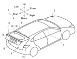
図1は、本発明の実施形態に係るリアゲート10を有する自動車1の斜視図である。図1において、リアゲート10は、開いている。
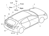
図2は、図1の自動車1のリアゲート10を閉じた状態を示す図である。
Fig. 1 is a perspective view of an automobile 1 having a tailgate 10 according to an embodiment of the present invention. In Fig. 1, the tailgate 10 is open.
FIG. 2 is a diagram showing the rear gate 10 of the automobile 1 of FIG. 1 in a closed state.

図1の自動車1は、車両の一例である。自動車1は、車室3が画成される車体2を有する。自動車1の車体2には、車室3に対して乗員が乗降するための複数のドアとともに、車室3の後部である荷室にアクセスするためのリアゲート10を有する。リアゲート10は、その上縁部分が一対のヒンジ部材6により、車体2のルーフ部分に取り付けられている。
リアゲート10を開くと、図1に示すように、自動車1の車体2に後部開口4が現れる。乗員は、後部開口4から荷室の荷物を出し入れすることができる。また、乗員は、開いているリアゲート10を引き下げる。これにより、リアゲート10は、図2のように閉じる。自動車1の車体2の後部開口4は、閉塞される。荷室の荷物は、後部開口4から脱落しない。
このようにリアゲート10は、自動車1の後部開口4に対して開閉可能に設けられる。
An automobile 1 in Fig. 1 is an example of a vehicle. The automobile 1 has a body 2 that defines a passenger compartment 3. The body 2 of the automobile 1 has a plurality of doors for passengers to get in and out of the passenger compartment 3, as well as a rear gate 10 for accessing a luggage compartment at the rear of the passenger compartment 3. The upper edge portion of the rear gate 10 is attached to the roof portion of the body 2 by a pair of hinge members 6.
When the rear gate 10 is opened, a rear opening 4 appears in the body 2 of the automobile 1, as shown in Fig. 1. A passenger can put in or take out luggage from the luggage compartment through the rear opening 4. The passenger also pulls down the open rear gate 10. This causes the rear gate 10 to close, as shown in Fig. 2. The rear opening 4 of the body 2 of the automobile 1 is closed. Luggage in the luggage compartment does not fall out through the rear opening 4.
In this manner, the rear gate 10 is provided so as to be capable of being opened and closed relative to the rear opening 4 of the automobile 1 .

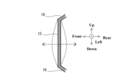
図3は、図1のリアゲート10を平らに展開した模式的な説明図である。図3の模式的なリアゲート10は、図1の自動車1の後方から見たものである。
図4は、図3の模式的なリアゲート10の開閉動作を説明するための側面図である。
図3以降の図面において、前後左右上下の各方向は、図2のようにリアゲート10を閉じた状態について示している。
図3および図4に示すように、リアゲート10は、インナパネル11と、インナパネル11の外側に重ね合わされるアウタパネル12と、を有する。
Fig. 3 is a schematic explanatory diagram of the tailgate 10 of Fig. 1 laid flat. The schematic tailgate 10 of Fig. 3 is seen from the rear of the automobile 1 of Fig. 1.
FIG. 4 is a side view for explaining the opening and closing operation of the schematic rear gate 10 of FIG.
In FIG. 3 and subsequent figures, the front, rear, left, right, top and bottom directions are shown in a state where the rear gate 10 is closed as in FIG.
As shown in FIGS. 3 and 4 , the rear gate 10 has an inner panel 11 and an outer panel 12 that is overlapped on the outside of the inner panel 11 .

インナパネル11とアウタパネル12とは、自動車1の後部開口4を閉塞できるように、図3および図4に示すように略四角形の外形の鋼板を用いて、後部開口4に沿った外形に形成される。特に、アウタパネル12は、自動車1の外表面に露出し、自動車1の意匠を構成する。インナパネル11とアウタパネル12とは、一般的にプレス加工により所望の押し出し形状に成形される。インナパネル11の外周縁部とアウタパネル12の外周縁部とは重ね合わされ、接着剤により貼りあわされてよい。アウタパネル12の外周縁部は、インナパネル11の外周縁部の外側で折り曲げられて、折り曲げられた部分により、インナパネル11の外周縁部を把持してよい。このような構造で重ね合わされるインナパネル11とアウタパネル12とは、リアゲート10に求められている基本的な剛性を得ることが可能である。一対のヒンジ部材6は、基本的に、略四角形の鋼板のインナパネル11の上縁部に取り付けられてよい。これにより、一対のヒンジ部材6は、リアゲート10を閉じた状態で、図2に示すように、アウタパネル12により覆うことができる。 The inner panel 11 and the outer panel 12 are formed into a shape that conforms to the rear opening 4 of the automobile 1 using steel plates with an approximately rectangular outline as shown in Figs. 3 and 4 so that the rear opening 4 of the automobile 1 can be closed. In particular, the outer panel 12 is exposed to the outer surface of the automobile 1 and constitutes the design of the automobile 1. The inner panel 11 and the outer panel 12 are generally formed into a desired extrusion shape by press working. The outer peripheral edge of the inner panel 11 and the outer peripheral edge of the outer panel 12 may be overlapped and attached to each other with an adhesive. The outer peripheral edge of the outer panel 12 may be folded outside the outer peripheral edge of the inner panel 11, and the folded part may grip the outer peripheral edge of the inner panel 11. The inner panel 11 and the outer panel 12 overlapped in this structure can obtain the basic rigidity required for the rear gate 10. The pair of hinge members 6 may basically be attached to the upper edge of the inner panel 11, which is made of an approximately rectangular steel plate. As a result, when the rear gate 10 is closed, the pair of hinge members 6 can be covered by the outer panel 12, as shown in FIG. 2.

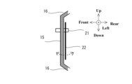
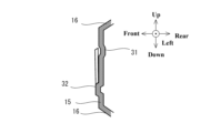
リアゲート10の上部には、略四角形の外形の鋼板を押し出し形状に成形してなるインナパネル11の上部とアウタパネル12の上部とを貫通させることにより、開口13が形成される。リアゲート10の上部の開口13には、リアガラス18が、たとえばアウタパネル12の外側から嵌め込まれる。なお、インナパネル11とアウタパネル12とは、開口13の周囲においても重ね合わされ、接着剤により貼りあわされてよい。また、アウタパネル12の開口縁部は、インナパネル11の開口縁部の内側で折り曲げられて、折り曲げられた部分によりインナパネル11の開口縁部を把持してよい。これにより、インナパネル11とアウタパネル12とは、それらの上部に大きな開口13が形成されているとしても、それらの上部の形状を保つための最低限の剛性を得ることが可能になる。 An opening 13 is formed in the upper part of the rear gate 10 by penetrating the upper part of the inner panel 11, which is formed by extruding a steel plate with a substantially rectangular outline, through the upper part of the outer panel 12. A rear glass 18 is fitted into the opening 13 in the upper part of the rear gate 10, for example, from the outside of the outer panel 12. The inner panel 11 and the outer panel 12 may be overlapped around the periphery of the opening 13 and attached together with an adhesive. The edge of the opening of the outer panel 12 may be folded inside the edge of the opening of the inner panel 11, and the folded part may grip the edge of the opening of the inner panel 11. This allows the inner panel 11 and the outer panel 12 to obtain a minimum rigidity to maintain the shape of their upper parts, even if a large opening 13 is formed in their upper parts.

リアゲート10のアウタパネル12の下部には、略四角形の平板状のライセンスプレート22を取り付けるための取付面部15が形成される。取付面部15は、後述するように、自動車1が登録される複数の国でのライセンスプレート22が取り付け可能となるように、複数種類のライセンスプレート22,23より大きい平面状に形成するとよい。また、各国の法規では、ライセンスプレートを取り付けるための取付面部15は、ライセンスプレートの視認性の確保などのために、基本的に平面にすることが求められている。なお、特定の国では、発光機能を有するライセンスプレートが法規において許容されている国がある。また、取付面部15には、将来的には、自動運転状態や速度といった走行状態を、点灯状態の変化により表示可能な表示部材が取り付けられる可能性がある。 The lower part of the outer panel 12 of the rear gate 10 is formed with a mounting surface 15 for mounting a flat license plate 22 having a substantially rectangular shape. As described below, the mounting surface 15 is preferably formed in a planar shape larger than the multiple types of license plates 22, 23 so that the license plate 22 can be mounted in the multiple countries in which the automobile 1 is registered. In addition, the laws and regulations of each country require that the mounting surface 15 for mounting the license plate be basically flat to ensure the visibility of the license plate. In addition, in some countries, the laws and regulations of certain countries allow license plates with a light-emitting function. In addition, in the future, the mounting surface 15 may be equipped with a display member that can display the driving state, such as the automatic driving state and the speed, by changing the lighting state.

取付面部15は、たとえばアウタパネル12をプレス加工により押し出し成形することにより、アウタパネル12に形成されてよい。本実施形態の取付面部15の周囲には、プレス加工での押し出し成形により湾曲してなる枠部16が形成されている。そして、取付面部15は、アウタパネル12についての取付面部15以外の残部と比べて、自動車1の前方向へ窪んだ状態で、アウタパネル12に形成されている。取付面部15は、その周囲に湾曲してなる枠部16が形成されることにより、アウタパネル12を補剛するように機能し得る。このような取付面部15が形成されることにより、アウタパネル12は、その全体において振動し難くなることが期待できる。 The mounting surface portion 15 may be formed on the outer panel 12, for example, by extruding the outer panel 12 through a press process. In this embodiment, a curved frame portion 16 is formed around the mounting surface portion 15 by the press process. The mounting surface portion 15 is formed on the outer panel 12 in a state recessed toward the front of the automobile 1 compared to the remaining portion of the outer panel 12 other than the mounting surface portion 15. The mounting surface portion 15 can function to stiffen the outer panel 12 by forming the curved frame portion 16 around it. By forming such a mounting surface portion 15, it is expected that the outer panel 12 will be less susceptible to vibration as a whole.

リアゲート10のアウタパネル12についての、リアガラス18のための開口13と取付面部15との間である、上下方向の中央部には、横断カバー部材14が設けられる。横断カバー部材14は、アウタパネル12の上下方向の中央部において、アウタパネル12の左右方向の全幅に渡って横長に設けられる。横長の横断カバー部材14は、図2に示すように、左右のリアランプ部材19の間に渡るように設けられる。横断カバー部材14は、左右のリアランプ部材19と一体的な意匠を形成する。なお、横断カバー部材14には、左右のリアランプ部材19と連動して点灯可能な不図示の点灯部材や、取付面部15に取り付けられるライセンスプレート22を照らすための不図示の点灯部材などが設けられてよい。 A cross cover member 14 is provided in the vertical center of the outer panel 12 of the rear gate 10 between the opening 13 for the rear glass 18 and the mounting surface 15. The cross cover member 14 is provided horizontally across the entire width of the outer panel 12 in the horizontal direction at the vertical center of the outer panel 12. As shown in FIG. 2, the horizontal cross cover member 14 is provided so as to span between the left and right rear lamp members 19. The cross cover member 14 forms an integrated design with the left and right rear lamp members 19. The cross cover member 14 may be provided with a lighting member (not shown) that can be turned on in conjunction with the left and right rear lamp members 19, or a lighting member (not shown) for illuminating the license plate 22 attached to the mounting surface 15.

リアゲート10の下縁の中央部分には、車体2に設けられるラッチ受け部材7と係合可能なラッチ部材8が設けられる。また、車体2には、リアゲート10の左縁部分または右縁部分と当接する左右一対の弾性部材20が設けられる。
これによりヒンジ部材6の周囲で回動するリアゲート10は、ラッチ部材8がラッチ受け部材7と係合し、かつ、リアゲート10の左縁部分および右縁部分が左右一対の弾性部材20と当接する状態において、車体2に対して閉じることができる。閉じられているリアゲート10は、車体2に対してガタついたり、車体2に対して振動したりし難くなる。リアゲート10の全体が振動することによる異音は、発生し難くなることが期待できる。
A latch member 8 engageable with a latch receiving member 7 provided on the vehicle body 2 is provided in the center of the lower edge of the rear gate 10. In addition, the vehicle body 2 is provided with a pair of left and right elastic members 20 that come into contact with the left and right edge portions of the rear gate 10.
As a result, the rear gate 10, which rotates around the hinge members 6, can be closed relative to the vehicle body 2 when the latch members 8 engage with the latch receiving members 7 and the left and right edge portions of the rear gate 10 abut against the pair of left and right elastic members 20. The closed rear gate 10 is less likely to rattle or vibrate relative to the vehicle body 2. It is expected that abnormal noise caused by the vibration of the entire rear gate 10 will be less likely to occur.

次に、ライセンスプレート22の法規に則った一般的な取付面部15について説明する。 Next, we will explain the general mounting surface portion 15 of the license plate 22 that complies with regulations.

図5は、リアゲート10のアウタパネル12に形成される一般的な平面状の取付面部15の縦断面図である。
図6は、図5の一般的な平面状の取付面部15に、表示部材としての平板状のライセンスプレート22を取り付けた状態を示す縦断面図である。
図5および図6に示すように、法規に則った取付面部15は、平面状に形成される。平面状の取付面部15の周囲には、プレス加工での押し出し成形により湾曲してなる枠部16が形成されている。
FIG. 5 is a vertical cross-sectional view of a typical flat mounting surface portion 15 formed on the outer panel 12 of the rear gate 10. As shown in FIG.
FIG. 6 is a vertical cross-sectional view showing a state in which a flat license plate 22 as a display member is attached to the general flat mounting surface portion 15 of FIG.
5 and 6, the mounting surface 15 conforming to regulations is formed in a flat shape. A curved frame 16 is formed around the flat mounting surface 15 by extrusion molding in a press process.

このように取付面部15が平面状に形成されている場合、図5に示すように、平面状の取付面部15は、取付面部15の全体において、振動する可能性がある。たとえば自動車1がアイドリングしている場合、自動車1が走行している場合、開いていたリアゲート10を閉じる場合、などにおいて、平面状の取付面部15は、振動する可能性がある。この平面状の取付面部15の振動は、インナパネル11とアウタパネル12とが重ね合わされてなるリアゲート10において増幅されて、自動車1の車室3に伝わる可能性がある。車室3に伝わった音は、異音として、自動車1の乗員に可聴され得る。乗員は、リアゲート10からの所謂こもり音を可聴する可能性がある。
なお、取付面部15は、基本的に、略四角形の平面状となるように枠部16により囲われる。この場合、平面状の取付面部15は、たとえば、略四角形の対角の長さに対応する固有周波数、図5のように略四角形の上縁から下縁までの長さに対応する固有周波数、略四角形の右縁から左縁までの長さに対応する固有周波数について共振し易いと考えられる。平面状の取付面部15は、いずれかの固有周波数の振動が入力されると、上述する各方向の軸において共振して振動し、取付面部15の全体において大きく振動し易くなると考えられる。
When the mounting surface portion 15 is formed in a flat shape in this way, as shown in Fig. 5, the flat mounting surface portion 15 may vibrate over the entire mounting surface portion 15. For example, when the automobile 1 is idling, when the automobile 1 is running, when the open rear gate 10 is closed, etc., the flat mounting surface portion 15 may vibrate. The vibration of the flat mounting surface portion 15 may be amplified in the rear gate 10 formed by overlapping the inner panel 11 and the outer panel 12, and may be transmitted to the passenger compartment 3 of the automobile 1. The sound transmitted to the passenger compartment 3 may be heard by the passengers of the automobile 1 as an abnormal sound. The passengers may hear a so-called muffled sound from the rear gate 10.
The mounting surface portion 15 is basically surrounded by the frame portion 16 so as to have a substantially rectangular planar shape. In this case, the planar mounting surface portion 15 is considered to easily resonate with a natural frequency corresponding to the length of the diagonal of the substantially rectangular shape, a natural frequency corresponding to the length from the upper edge to the lower edge of the substantially rectangular shape as shown in Fig. 5, and a natural frequency corresponding to the length from the right edge to the left edge of the substantially rectangular shape. When vibration of any of the natural frequencies is input to the planar mounting surface portion 15, it is considered that the planar mounting surface portion 15 resonates and vibrates on the axes in each of the above-mentioned directions, and the entire mounting surface portion 15 is likely to vibrate significantly.

このような対策のために、たとえば、リアゲート10を構成するインナパネル11の一部を、アウタパネル12へ向けて伸ばして、アウタパネル12に連結することが考えられる。これにより、リアゲート10のアウタパネル12に形成される略平面状の取付面部15の振動を抑制することが期待できる。しかしながら、この対策を実施するためには、インナパネル11などについての特別な追加の加工が必要になる。
この他にもたとえば、インナパネル11とアウタパネル12との間にリンフォースを介在させることが考えられる。これにより、リアゲート10のアウタパネル12に形成される略平面状の取付面部15の振動を抑制することが期待できる。しかしながら、この対策を実施するためには、インナパネル11とアウタパネル12との間にリンフォースを介在させるための工程が必要になる。
そして、いずれの対策の場合においても、自動車1のリアゲート10の構造は、複雑化する。また、リアゲート10は重くなり得る。
As a countermeasure for this, for example, it is conceivable to extend a part of the inner panel 11 constituting the rear gate 10 toward the outer panel 12 and connect it to the outer panel 12. This is expected to suppress vibration of the substantially planar mounting surface portion 15 formed on the outer panel 12 of the rear gate 10. However, in order to implement this countermeasure, special additional processing of the inner panel 11 etc. is required.
Another possible solution is to interpose a reinforcement between the inner panel 11 and the outer panel 12. This is expected to suppress vibrations of the substantially flat mounting surface portion 15 formed on the outer panel 12 of the rear gate 10. However, in order to implement this solution, a process for interposing the reinforcement between the inner panel 11 and the outer panel 12 is required.
In either case, the structure of the rear gate 10 of the automobile 1 becomes complicated. Also, the rear gate 10 may become heavy.

また、平面状の取付面部15に対して、平板状のライセンスプレート22を取り付ける場合、図6に示すように、平板状のライセンスプレート22は、振動する可能性がある。たとえば自動車1がアイドリングしている場合、自動車1が走行している場合、開いていたリアゲート10を閉じた場合、などにおいて、平板状のライセンスプレート22は、振動する可能性がある。この平板状のライセンスプレート22の振動は、インナパネル11とアウタパネル12とが重ね合わされてなるリアゲート10において増幅されて、自動車1の車室3に伝わる可能性がある。車室3に伝わった音は、異音として、自動車1の乗員に可聴され得る。乗員は、リアゲート10からの所謂ビレ音を可聴する可能性がある。
そして、この場合においても、上述した2種類の対策により、乗員に可聴されるビレ音を抑制することが期待し得る。
しかしながら、上述した2種類の対策は、平板状のライセンスプレート22そのものの振動発生を抑制できるものではない。
また、上述した2種類のいずれの対策の場合においても、自動車1のリアゲート10の構造が複雑化し、リアゲート10が重くなり得る。
Furthermore, when a flat license plate 22 is attached to the planar mounting surface portion 15, as shown in Fig. 6, the flat license plate 22 may vibrate. For example, when the automobile 1 is idling, when the automobile 1 is running, when the open rear gate 10 is closed, etc., the flat license plate 22 may vibrate. The vibration of the flat license plate 22 may be amplified in the rear gate 10, which is formed by overlapping the inner panel 11 and the outer panel 12, and may be transmitted to the passenger compartment 3 of the automobile 1. The sound transmitted to the passenger compartment 3 may be heard by the passengers of the automobile 1 as an abnormal sound. The passengers may hear a so-called rattling sound from the rear gate 10.
Even in this case, it is expected that the rattle noise audible to the occupants can be suppressed by taking the above-mentioned two types of measures.
However, the above-mentioned two types of measures cannot suppress the vibration of the flat license plate 22 itself.
In addition, in either of the two types of measures described above, the structure of the rear gate 10 of the automobile 1 becomes complicated, and the rear gate 10 may become heavy.

このように、自動車1のリアゲート10では、自動車1のリアゲート構造の複雑化を抑制しながら、取付面部15やそれに取り付けられるライセンスプレート22などの表示部材の振動を抑制して、リアゲート10からの異音の発生を抑制することが求められている。 In this way, the rear gate 10 of the automobile 1 is required to suppress the generation of abnormal noise from the rear gate 10 by suppressing vibration of the mounting surface portion 15 and display members such as the license plate 22 attached thereto, while preventing the rear gate structure of the automobile 1 from becoming too complicated.

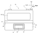
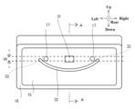
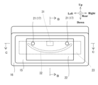
図7は、本実施形態に係る取付面部15の説明図である。図7の取付面部15は、図1の自動車1の後方から見たものである。
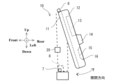
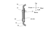
図8は、図7の取付面部15についての模式的なA-A縦断面図である。図7のA-A縦断面は、取付面部15についての、左右方向中央における縦断面である。
7 is an explanatory diagram of the mounting surface portion 15 according to this embodiment. The mounting surface portion 15 in FIG. 7 is seen from the rear of the automobile 1 in FIG.
Fig. 8 is a schematic vertical cross-sectional view of the mounting surface portion 15 taken along line AA in Fig. 7. The vertical cross-section of Fig. 7 is a vertical cross-section of the mounting surface portion 15 at the center in the left-right direction.

図7および図8に示すように、本実施形態の取付面部15は、アウタパネル12において、基本的に平面状に形成される。平面状の取付面部15の周囲には、プレス加工での押し出し成形により湾曲してなる枠部16が形成されている。
また、取付面部15には、複数の支持孔17とともに、第一ビード部31、第二ビード部32、が形成される。
7 and 8, the mounting surface portion 15 of this embodiment is basically formed in a flat shape on the outer panel 12. A curved frame portion 16 is formed around the flat mounting surface portion 15 by extrusion molding in a press process.
In addition, the mounting surface portion 15 is formed with a plurality of support holes 17 as well as a first bead portion 31 and a second bead portion 32 .

支持孔17は、平板状のライセンスプレート22を、アウタパネル12の下部に形成される取付面部15の外面に取り付けるために、アウタパネル12の平面状の取付面部15に開設される孔である。支持孔17は、ネジやビスといった固定部材21を用いて、平板状のライセンスプレート22の孔と共締めされる。これにより、平板状のライセンスプレート22は、取付面部15の外面に支持されるように取り付けられる。
複数の支持孔17は、取付面部15において、少なくとも左右一対にて形成されるとよい。左右一対の支持孔17は、取付面部15において、自動車1の左右方向に沿って並べて形成される。複数の支持孔17は、取付面部15において、左右一対を1組として、複数組が上下に並べて形成されもよい。複数の支持孔17は、自動車1が使用される国に応じて、取付面部15に開設されればよい。
なお、平板状のライセンスプレート22の替わりに、他の表示部材を取付面部15の外面に取り付ける場合でも、複数の支持孔17は、固定部材21を用いて、他の表示部材の孔と共締めされてよい。
また、取付面部15には、複数の支持孔17の替わりに、複数の支持凸部が形成されてもよい。この場合、平板状のライセンスプレート22は、ライセンスプレート22の各孔に各支持凸部を挿入することにより、取付面部15の外面に支持されるように取り付けられ得る。
The support holes 17 are holes formed in the planar mounting surface portion 15 of the outer panel 12 in order to mount the flat license plate 22 to the outer surface of the mounting surface portion 15 formed in the lower part of the outer panel 12. The support holes 17 are fastened together with holes in the flat license plate 22 using fixing members 21 such as screws or bolts. In this way, the flat license plate 22 is attached so as to be supported by the outer surface of the mounting surface portion 15.
The multiple support holes 17 may be formed in at least a left-right pair in the mounting surface portion 15. The pair of left-right support holes 17 are formed side by side along the left-right direction of the automobile 1 in the mounting surface portion 15. The multiple support holes 17 may be formed in multiple sets lined up above and below, with a left-right pair being one set, in the mounting surface portion 15. The multiple support holes 17 may be opened in the mounting surface portion 15 according to the country in which the automobile 1 is used.
In addition, even if another display member is attached to the outer surface of the mounting surface portion 15 instead of the flat license plate 22, the multiple support holes 17 may be fastened together with the holes of the other display member using the fixing member 21.
Furthermore, mounting surface portion 15 may be formed with a plurality of support protrusions instead of a plurality of support holes 17. In this case, flat license plate 22 can be attached so as to be supported by the outer surface of mounting surface portion 15 by inserting each support protrusion into each hole of license plate 22.

第一ビード部31は、アウタパネル12の下部に形成される取付面部15において、左右一対の支持孔17の間に形成される。図7において、第一ビード部31は、左右一対の支持孔17の中央位置において、略四角形に形成されている。
第一ビード部31は、たとえばアウタパネル12をプレス加工などにより押し出し成形する際に、アウタパネル12の取付面部15を押し出して変形させることにより、取付面部15に形成されてよい。
略四角形の第一ビード部31は、図7に示すように、その上下幅が、支持孔17の上下幅Wと同等となるように形成されてよい。
第一ビード部31は、図8に示すように、取付面部15から後方へ向けて突出するように、取付面部15に形成される。これにより、第一ビード部31は、左右一対の支持孔17の間において、取付面部15の外面から突出するように形成されることになる。
The first bead portion 31 is formed between a pair of left and right support holes 17 on the mounting surface portion 15 formed on the lower part of the outer panel 12. In Fig. 7, the first bead portion 31 is formed in a substantially rectangular shape at the center position of the pair of left and right support holes 17.
The first bead portion 31 may be formed on the mounting surface portion 15 of the outer panel 12 by extruding and deforming the mounting surface portion 15 when the outer panel 12 is extruded by press working or the like, for example.
The substantially rectangular first bead portion 31 may be formed so that its vertical width is equal to the vertical width W of the support hole 17, as shown in FIG.
8, the first bead portion 31 is formed on the mounting surface portion 15 so as to protrude rearward from the mounting surface portion 15. As a result, the first bead portion 31 is formed so as to protrude from the outer surface of the mounting surface portion 15 between the pair of left and right support holes 17.

第二ビード部32は、アウタパネル12の下部に形成される取付面部15において、角を持たないように円弧状に形成される。
第二ビード部32は、アウタパネル12をプレス加工などにより押し出し成形する際に、アウタパネル12の取付面部15を押し出して変形させることにより、取付面部15に形成されてよい。
円弧状の第二ビード部32は、図7に示すように、取付面部15において、左右一対の支持孔17の下側に形成される。円弧状の第二ビード部32は、取付面部15において、左右一対の支持孔17と自動車1の上下方向において並ぶように形成される。
円弧状の第二ビード部32は、円弧状の中央部分を最下端とし、円弧状の両端部33が上方へ延びるように、取付面部15に形成される。第二ビード部32についての円弧状の両端部33は、円弧状の中央部分より、上側に位置する。
そして、左右一対の支持孔17の下側に並ぶように形成される第二ビード部32についての、円弧状の両端部は、左右一対の支持孔17が形成される高さ位置まで延在する。円弧状の第二ビード部32は、左右一対の支持孔17の上下幅Wの範囲に両端が重なるように延在して形成される。なお、円弧状の両端部は、左右一対の支持孔17より上側となる高さ位置まで延在してもよい。
その結果、円弧状の両端部は、取付面部15において、左右一対の支持孔17についての左右両外側に位置することになる。
また、円弧状の第二ビード部32は、少なくとも左側の支持孔17から右側の支持孔17までの左右方向の幅に渡って延在するように形成されることになる。
第二ビード部32は、図8に示すように、取付面部15から前方へ向けて突出するように、取付面部15に形成される。これにより、第二ビード部32は、取付面部15の外面から突出しないように形成されることになる。
The second bead portion 32 is formed in an arc shape without any corners on the mounting surface portion 15 formed on the lower part of the outer panel 12 .
The second bead portion 32 may be formed on the mounting surface portion 15 of the outer panel 12 by extruding and deforming the mounting surface portion 15 when the outer panel 12 is extruded by press working or the like.
7, the arc-shaped second bead portion 32 is formed on the mounting surface portion 15 below the pair of left and right support holes 17. The arc-shaped second bead portion 32 is formed on the mounting surface portion 15 so as to be aligned with the pair of left and right support holes 17 in the up-down direction of the automobile 1.
The arc-shaped second bead portion 32 is formed on the mounting surface portion 15 so that the arc-shaped central portion is the lowest end and both arc-shaped ends 33 extend upward. The arc-shaped ends 33 of the second bead portion 32 are located above the arc-shaped central portion.
The arc-shaped second bead portion 32 formed to align below the pair of left and right support holes 17 has both ends extending to a height position at which the pair of left and right support holes 17 are formed. The arc-shaped second bead portion 32 is formed extending such that both ends overlap within the range of the vertical width W of the pair of left and right support holes 17. Note that both ends of the arc-shaped second bead portion 32 may extend to a height position above the pair of left and right support holes 17.
As a result, both arcuate ends are located on the left and right outer sides of the pair of left and right support holes 17 on the mounting surface portion 15 .
The arc-shaped second bead portion 32 is formed so as to extend at least across the width in the left-right direction from the left support hole 17 to the right support hole 17 .
8, the second bead portion 32 is formed on the mounting surface portion 15 so as to protrude forward from the mounting surface portion 15. As a result, the second bead portion 32 is formed so as not to protrude from the outer surface of the mounting surface portion 15.

そして、このような円弧状の第二ビード部32が形成されることにより、平面状の取付面部15の剛性が高まり、取付面部15は、その全体が振動することが起き難くなる。
特に、本実施形態の第二ビード部32は、角のない円弧状に形成されている。これにより、平面状の取付面部15は、その略四角形の対角方向の軸、左右方向の軸、および、上下方向の軸において全体的に振動してしまうことが起き難くなる。
これに対し、仮にたとえば、第二ビード部32が左右方向の直線状に形成されている場合、第二ビード部32は、平面状の取付面部15が上下方向の軸において全体的に振動してしまうことを抑制し難い。
この他にもたとえば、第二ビード部32が上下方向の直線状に形成されている場合、第二ビード部32は、平面状の取付面部15が左右方向の軸において全体的に振動してしまうことを抑制し難い。
この他にもたとえば、第二ビード部32がV字形状に形成されている場合、第二ビード部32は、平面状の取付面部15が全体的に振動してしまうことを抑制し得る可能性があるが、V字の下角部分と取付面部15の周縁部分との距離に対応する固有振動数について共振し易くなる可能性がある。この場合、平面状の取付面部15は、上述したものとは異なる周波数で振動し易くなる可能性がある。
Furthermore, by forming such an arc-shaped second bead portion 32, the rigidity of the planar mounting surface portion 15 is increased, and the mounting surface portion 15 as a whole is less likely to vibrate.
In particular, the second bead portion 32 in this embodiment is formed in a corner-free arc shape, which makes it difficult for the planar mounting surface portion 15 to vibrate overall about the diagonal axes, left-right axis, and up-down axis of the substantially rectangular shape.
In contrast, if the second bead portion 32 is formed in a straight line in the left-right direction, for example, the second bead portion 32 has difficulty in suppressing the planar mounting surface portion 15 from vibrating overall on the up-down axis.
In addition, for example, if the second bead portion 32 is formed in a straight line in the vertical direction, the second bead portion 32 has difficulty in suppressing the planar mounting surface portion 15 from vibrating overall on the left-right axis.
In addition, for example, when the second bead portion 32 is formed in a V-shape, the second bead portion 32 may be able to suppress the planar mounting surface portion 15 from vibrating as a whole, but may be prone to resonating at a natural frequency corresponding to the distance between the lower corner of the V-shape and the peripheral edge of the mounting surface portion 15. In this case, the planar mounting surface portion 15 may be prone to vibrating at a frequency different from that described above.

図9は、図7の取付面部15に、表示部材としての平板状のライセンスプレート22を取り付けた状態の説明図である。
図10は、図9の取付面部15および平板状のライセンスプレート22についての一例の模式的なB-B縦断面図である。図9のB-B縦断面は、取付面部15についての、左右方向中央での縦断面である。
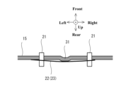
図11は、図9の取付面部15および平板状のライセンスプレート22についての一例の模式的なC-C横断面図である。図9のC-C縦断面は、取付面部15についての、左右一対の支持孔17が形成される高さ位置での横縦断である。
FIG. 9 is an explanatory diagram showing a state in which a flat license plate 22 as a display member is attached to the attachment surface portion 15 of FIG.
Fig. 10 is a schematic BB vertical cross-sectional view of an example of the mounting surface portion 15 and the flat license plate 22 of Fig. 9. The BB vertical cross-section of Fig. 9 is a vertical cross-section of the mounting surface portion 15 at the center in the left-right direction.
Fig. 11 is a schematic cross-sectional view taken along CC of an example of the mounting surface 15 and flat license plate 22 shown in Fig. 9. The CC cross-section in Fig. 9 is a cross-sectional view of the mounting surface 15 at a height position where a pair of left and right support holes 17 are formed.

図9には、日本国のライセンスプレート22が、取付面部15に取り付けられている。欧州の各国でのライセンスプレート23には、図9において破線で示すように、日本国のライセンスプレート22と比べて、上下方向の縦幅が狭く、かつ、左右方向の横幅が広いものが多い。そして、これらのライセンスプレート22,23は、共通する左右一対の支持孔17により、取付面部15の外面に取り付けることが可能である。この場合、取付面部15は、左右方向の幅が、欧州の各国でのライセンスプレート23の横幅より広く、かつ、上下方向の幅が、日本国のライセンスプレート22の縦幅より広くなるサイズに形成することが望まれる。
図7から図11に示す取付面部15は、互いに外形が異なる複数のライセンスプレート22,23を取り付け可能な大きなサイズに形成されている。
In Fig. 9, a Japanese license plate 22 is attached to the mounting surface portion 15. As shown by the dashed line in Fig. 9, many European license plates 23 are narrower in vertical width and wider in horizontal width than the Japanese license plate 22. These license plates 22, 23 can be attached to the outer surface of the mounting surface portion 15 by a common pair of left and right support holes 17. In this case, it is desirable to form the mounting surface portion 15 in a size such that the horizontal width is wider than the horizontal width of the European license plate 23 and the vertical width is wider than the vertical width of the Japanese license plate 22.
The mounting surface portion 15 shown in FIGS. 7 to 11 is formed in a large size capable of mounting a plurality of license plates 22, 23 having different outer shapes.

そして、本実施形態において、左右一対の支持孔17の中央位置に形成される第一ビード部31は、欧州の各国でのライセンスプレート22および日本国のライセンスプレート22により共に覆われる範囲内に収まるように、取付面部15に形成される。
また、第一ビード部31の下側に形成される円弧状の第二ビード部32は、欧州の各国でのライセンスプレート22および日本国のライセンスプレート22により共に覆われる範囲内に収まるように、取付面部15に形成される。
このように第一ビード部31と第二ビード部32とは、取付面部15についての、複数のライセンスプレート22により重複して覆われる範囲内に、形成される。
In this embodiment, the first bead portion 31 formed in the central position of the pair of left and right support holes 17 is formed on the mounting surface portion 15 so as to fall within the range covered by both the license plate 22 for each European country and the license plate 22 for Japan.
In addition, the arc-shaped second bead portion 32 formed below the first bead portion 31 is formed on the mounting surface portion 15 so as to fall within the range covered by both the license plate 22 for each European country and the license plate 22 for Japan.
In this manner, the first bead portion 31 and the second bead portion 32 are formed within the area of the mounting surface portion 15 that is overlappingly covered by a plurality of license plates 22 .

このように、本実施形態の平面状の取付面部15には、第一ビード部31と第二ビード部32とが形成される。本実施形態の平面状の取付面部15は、図5のものと比べて、取付面部15の全体において湾曲して振動することが起き難くなる。 In this manner, the planar mounting surface portion 15 of this embodiment is formed with a first bead portion 31 and a second bead portion 32. Compared to the planar mounting surface portion 15 of FIG. 5, the planar mounting surface portion 15 of this embodiment is less likely to bend and vibrate across the entire mounting surface portion 15.

また、第一ビード部31は、図10の縦断面に示すように、左右一対の支持孔17の間において、取付面部15の外面から後方へ向けて突出するように形成される。このため、第一ビード部31は、左右一対の支持孔17の間において、取付面部15に取り付けられているライセンスプレート22の裏面(前面)に当たる。
そして、左右一対の支持孔17に対して固定部材21を用いて共締めされるライセンスプレート22は、図11に示すように、微妙に湾曲し得る。なお、平板状のライセンスプレート22についての左右方向での湾曲の程度は、第一ビード部31についての取付面部15からの突出高さ(前後方向での高さ)により調整することができる。平板状のライセンスプレート22は、取付面部15に取り付けられている状態において、左右一対の支持孔17において支持されるだけでなく、それらの間において第一ビード部31と密着して支持され得る。平板状のライセンスプレート22は、取付面部15に対して、微小に湾曲した状態で取り付けられることにより、その全体が振動することが起き難くなる。平板状のライセンスプレート22は、図6の取り付け状態と比べて、全体が振動し難くなる。
10 , the first bead portion 31 is formed to protrude rearward from the outer surface of the mounting surface portion 15 between the pair of left and right support holes 17. Therefore, the first bead portion 31 abuts against the back surface (front surface) of the license plate 22 attached to the mounting surface portion 15 between the pair of left and right support holes 17.
The license plate 22, which is fastened together with the pair of left and right support holes 17 by the fixing members 21, may be slightly curved as shown in FIG. 11. The degree of curvature in the left and right direction of the flat license plate 22 can be adjusted by the protruding height (height in the front-rear direction) of the first bead portion 31 from the mounting surface portion 15. When the flat license plate 22 is attached to the mounting surface portion 15, it is not only supported by the pair of left and right support holes 17, but can also be supported in close contact with the first bead portion 31 between them. The flat license plate 22 is attached to the mounting surface portion 15 in a slightly curved state, so that the entire plate is less likely to vibrate. The flat license plate 22 is less likely to vibrate as a whole compared to the mounting state shown in FIG. 6.

また、第二ビード部32は、取付面部15に取り付けられた平板状のライセンスプレート22により、外部から視認できないように覆われる。取付面部15に取り付けられた平板状のライセンスプレート22の周囲には、取付面部15についての平面状の部分のみが露出する。平板状のライセンスプレート22の周辺の視認状態は、取付面部15に対して第一ビード部31や第二ビード部32が形成されていない場合と同様になる。 The second bead portion 32 is covered by the flat license plate 22 attached to the mounting surface portion 15 so that it cannot be seen from the outside. Only the planar portion of the mounting surface portion 15 is exposed around the flat license plate 22 attached to the mounting surface portion 15. The visibility of the periphery of the flat license plate 22 is the same as when the first bead portion 31 and the second bead portion 32 are not formed on the mounting surface portion 15.

このように、平板状のライセンスプレート22は、第一ビード部31が裏面(前面)に当たることにより、振動し難くなる。平板状のライセンスプレート22は、左右一対の支持孔17および第一ビード部31により、平面状の取付面部15の上において振動し難くなるようにしっかりと固定される。
また、平面状の取付面部15についての、平板状のライセンスプレート22に覆われる範囲には、円弧状の第二ビード部32が全体的に形成される。
これにより、図10の縦断面に示すように、平面状の取付面部15とその上に取り付けられる平板状のライセンスプレート22の下端とが近接していたとしても、これらが当接することは極めて起き難くなると期待できる。
In this manner, flat license plate 22 is less likely to vibrate because first bead portion 31 abuts against the back surface (front surface). Flat license plate 22 is firmly fixed on planar mounting surface 15 by pair of left and right support holes 17 and first bead portion 31 so as to be less likely to vibrate.
Additionally, an arc-shaped second bead portion 32 is formed over the entire area of the planar mounting surface portion 15 that is covered by the flat license plate 22 .
As a result, as shown in the vertical cross section of Figure 10, even if the planar mounting surface portion 15 and the lower end of the flat license plate 22 mounted thereon are close to each other, it is expected that they will be extremely unlikely to come into contact with each other.

以上のように、本実施形態では、自動車1の表示部材としての平板状のライセンスプレート22を取り付けるための取付面部15に、少なくとも左右一対にて形成される複数の支持孔17とともに、第一ビード部31と、第二ビード部32とを形成する。そして、第一ビード部31は、取付面部15の左右一対の支持孔17の間に形成される。また、第二ビード部32は、少なくとも左側の支持孔17から右側の支持孔17までの幅に渡って延在するように形成される。
これにより、本実施形態において、取付面部15または取付面部15に取り付けられる表示部材は、振動し難くなり、それらが振動することにより生じ得る異音が発生し難くなることが期待できる。その結果、本実施形態では、リアゲート10からの異音の発生を抑制することが期待できる。
しかも、本実施形態において、第一ビード部31は、アウタパネル12をプレス加工により押し出し成形する際に、アウタパネル12の取付面部15を押し出して変形させることにより、取付面部15に形成される。また、第二ビード部32は、アウタパネル12をプレス加工により押し出し成形する際に、アウタパネル12の取付面部15を押し出して変形させることにより、取付面部15に形成される。このように本実施形態では、アウタパネル12をプレス加工により押し出し成形する際に、アウタパネル12に形成される略平面状の取付面部15そのものを変形させることにより、第一ビード部31と、第二ビード部32とを取付面部15に形成する。このため、取付面部15またはそれに取り付けられている表示部材が振動することを抑制するために、たとえばインナパネル11の一部をアウタパネル12まで延在させてアウタパネル12に連結するように加工したり、インナパネル11とアウタパネル12との間にリンフォースなどの補剛部材を介在させたり、する必要性がない。本実施形態では、アウタパネル12をプレス加工により押し出し成形するだけで、取付面部15に第一ビード部31と第二ビード部32とを形成し、取付面部15または取付面部15に取り付けられている表示部材の振動を抑制し得る。本実施形態は、自動車1のリアゲート10の構造についての複雑化を抑制しながら、取付面部15やそれに取り付けられる表示部材の振動を抑制して、リアゲート10からの異音の発生を抑制することが期待できる。
As described above, in this embodiment, the first bead portion 31 and the second bead portion 32 are formed together with a plurality of support holes 17 formed in at least a left-right pair on the mounting surface portion 15 for mounting the flat license plate 22 as a display member of the automobile 1. The first bead portion 31 is formed between the left-right pair of support holes 17 on the mounting surface portion 15. The second bead portion 32 is formed to extend at least across the width from the left support hole 17 to the right support hole 17.
As a result, in this embodiment, the mounting surface portion 15 or the display member attached to the mounting surface portion 15 is less likely to vibrate, and it is expected that abnormal noise caused by the vibration of the mounting surface portion 15 is less likely to occur. As a result, in this embodiment, it is expected that the generation of abnormal noise from the rear gate 10 can be suppressed.
Moreover, in this embodiment, the first bead portion 31 is formed on the mounting surface portion 15 by pushing and deforming the mounting surface portion 15 of the outer panel 12 when the outer panel 12 is extruded by press working. Also, the second bead portion 32 is formed on the mounting surface portion 15 by pushing and deforming the mounting surface portion 15 of the outer panel 12 when the outer panel 12 is extruded by press working. In this manner, in this embodiment, when the outer panel 12 is extruded by press working, the substantially planar mounting surface portion 15 itself formed on the outer panel 12 is deformed to form the first bead portion 31 and the second bead portion 32 on the mounting surface portion 15. For this reason, in order to suppress vibration of the mounting surface portion 15 or the display member attached thereto, for example, it is not necessary to process a part of the inner panel 11 to extend to the outer panel 12 and connect it to the outer panel 12, or to interpose a stiffening member such as a reinforcement between the inner panel 11 and the outer panel 12. In this embodiment, the first bead portion 31 and the second bead portion 32 can be formed on the mounting surface portion 15 simply by extruding the outer panel 12 by press working, thereby making it possible to suppress vibrations of the mounting surface portion 15 or the display member attached to the mounting surface portion 15. This embodiment is expected to suppress the generation of abnormal noise from the rear gate 10 by suppressing vibrations of the mounting surface portion 15 and the display member attached thereto, while suppressing the complexity of the structure of the rear gate 10 of the automobile 1.

また、本実施形態において、第一ビード部31は、左右一対の支持孔17の間となる位置において、取付面部15の外面から突出するように形成される。
これにより、本実施形態では、取付面部15の外面から突出する第一ビード部31は、左右一対の支持孔17の間となる位置において、左右一対の支持孔17により取付面部15の外面に取り付けられる表示部材に対して当接することができる。表示部材は、取付面部15の外面に取り付けられた状態で、ガタつかないようにしっかりと支持され得る。表示部材は、第一ビード部31により押圧された状態で、左右一対の支持孔17に取り付けられることで、取付面部15の面状に載せるように取り付けられる場合よりもしっかりと支持され得る。表示部材がガタつくことに起因するビレ音などの異音の発生を効果的に抑制することが期待できる。
また、第一ビード部31とともに、左側の支持孔17から右側の支持孔17までの幅に渡って延在するように形成される第二ビード部32が設けられているため、第一ビード部31が左右一対の支持孔17の間において表示部材に当接していたとしても、取付面部15は、その本来の略平面状の形状を維持することができる。
In this embodiment, the first bead portion 31 is formed so as to protrude from the outer surface of the mounting surface portion 15 at a position between the pair of left and right support holes 17 .
As a result, in this embodiment, the first bead portion 31 protruding from the outer surface of the mounting surface portion 15 can abut against the indicating member attached to the outer surface of the mounting surface portion 15 through the pair of left and right support holes 17 at a position between the pair of left and right support holes 17. The indicating member can be firmly supported without rattling when attached to the outer surface of the mounting surface portion 15. By attaching the indicating member to the pair of left and right support holes 17 while being pressed by the first bead portion 31, the indicating member can be supported more firmly than when attached so as to rest on the surface of the mounting surface portion 15. It is expected that the generation of abnormal noises such as rattling caused by rattling of the indicating member can be effectively suppressed.
In addition, together with the first bead portion 31, a second bead portion 32 is provided which is formed to extend across the width from the left support hole 17 to the right support hole 17. Therefore, even if the first bead portion 31 abuts against the display member between a pair of left and right support holes 17, the mounting surface portion 15 can maintain its original approximately planar shape.

また、本実施形態において、第二ビード部32は、取付面部15において、左右一対の支持孔17と自動車1の上下方向において並ぶように、角を持たないように円弧状に形成される。そして、第二ビード部32についての円弧状の両端部33は、取付面部15において、左右一対の支持孔17についての左右両外側に位置する。第二ビード部32についての円弧状の両端部33は、左右一対の支持孔17の上下幅Wの範囲において、左右一対の支持孔17の左右両外側に位置する。
これにより、本実施形態では、第二ビード部32は、取付面部15の全体が、自動車1の左右方向の軸において振動してしまうことを抑制するだけでなく、その他の方向の軸、たとえば自動車1の上下方向の軸において振動してしまうことを抑制できる。取付面部15が振動することによるこもり音の発生を効果的に抑制することが期待できる。リアゲート10を、プレス加工により成形されるインナパネル11とプレス加工により成形されるアウタパネル12とを重ね合わせて形成して、リアゲート10の内部空間において異音が増幅され得る構造となっていたとしても、取付面部15が振動することに起因するリアゲート10からのこもり音などの異音の発生を効果的に抑制することが期待できる。
これに対し、仮にたとえば第二ビード部32が、たとえば単に左右方向に直線状に形成されたり、V字形状に形成されたりしている場合、取付面部15は、自動車1の上下方向の軸において振動したり、V字の折れ曲がり部分を基点として折れ曲がるように振動したりしてしまう能性がある。この場合、第二ビード部32を設けない場合とは異なる振動により、リアゲート10からのこもり音などの異音が発生してしまう可能性がある。
特に、本実施形態では、第二ビード部32についての円弧状の両端が、左右一対の支持孔17についての左右両外側に位置する。これにより、自動車1の上下方向において、左右一対の支持孔17と第二ビード部32とは離間しないようになる。取付面部15は、左右一対の支持孔17と、それと上下に並んで形成される第二ビード部32との間において折れ曲がるように変形し難くなる。取付面部15の振動は、より一層効果的に抑制し得る。リアゲート10からのこもり音などの異音の発生も、より効果的に抑制し得る。
In this embodiment, the second bead portion 32 is formed in an arc shape without any corners on the mounting surface portion 15 so as to be aligned with the pair of left and right support holes 17 in the up-down direction of the automobile 1. Both arc-shaped ends 33 of the second bead portion 32 are located on both left and right outer sides of the pair of left and right support holes 17 on the mounting surface portion 15. Both arc-shaped ends 33 of the second bead portion 32 are located on both left and right outer sides of the pair of left and right support holes 17 within the range of the up-down width W of the pair of left and right support holes 17.
As a result, in this embodiment, the second bead portion 32 can suppress not only the entire mounting surface portion 15 from vibrating about the left-right axis of the automobile 1, but also the vibration about an axis in another direction, such as the up-down axis of the automobile 1. It is expected that the generation of muffled noise caused by the vibration of the mounting surface portion 15 can be effectively suppressed. Even if the rear gate 10 is formed by overlapping the inner panel 11 formed by pressing and the outer panel 12 formed by pressing, and has a structure in which abnormal noise can be amplified in the internal space of the rear gate 10, it is expected that the generation of abnormal noise such as muffled noise from the rear gate 10 caused by the vibration of the mounting surface portion 15 can be effectively suppressed.
In contrast, if the second bead portion 32 is simply formed in a straight line in the left-right direction or in a V-shape, the mounting surface portion 15 may vibrate on the vertical axis of the automobile 1 or vibrate in a bending manner with the bending portion of the V as the base point. In this case, abnormal noises such as a muffled sound may be generated from the rear gate 10 due to vibrations different from those in the case where the second bead portion 32 is not provided.
In particular, in this embodiment, both ends of the arc shape of the second bead portion 32 are located on both the left and right outer sides of the pair of left and right support holes 17. This prevents the pair of left and right support holes 17 and the second bead portion 32 from being separated in the vertical direction of the automobile 1. The mounting surface portion 15 is less likely to bend and deform between the pair of left and right support holes 17 and the second bead portion 32 formed next to them above and below. Vibrations of the mounting surface portion 15 can be more effectively suppressed. The generation of abnormal noises, such as muffled sounds, from the rear gate 10 can also be more effectively suppressed.

また、本実施形態において、取付面部15は、アウタパネル12をプレス加工により押し出し成形することにより、アウタパネル12に形成されている。
この場合、アウタパネル12についての取付面部15の周囲には、プレス加工による押し出し成形により湾曲した枠部16が形成され得る。そして、取付面部15は、アウタパネル12についての取付面部15以外の残部と比べて、自動車1の前方向へ窪んだ面となるように、アウタパネル12に形成される。取付面部15は、アウタパネル12を補剛するように機能し得る。アウタパネル12は、その全体において振動し難くなる。
しかも、本実施形態では、このような独立性が高い面構造となる取付面部15についての振動を、第一ビード部31および第二ビード部32により抑制することができる。
その結果、本実施形態では、アウタパネル12が振動することにより乗員に可聴される異音を、効果的に抑制することが期待できる。
In this embodiment, the mounting surface portion 15 is formed on the outer panel 12 by extruding the outer panel 12 through a press process.
In this case, a curved frame portion 16 may be formed around the mounting surface portion 15 of the outer panel 12 by extrusion molding through press working. The mounting surface portion 15 is formed on the outer panel 12 so as to form a surface that is recessed toward the front of the automobile 1 compared to the remaining portion of the outer panel 12 other than the mounting surface portion 15. The mounting surface portion 15 may function to stiffen the outer panel 12. The outer panel 12 as a whole becomes less susceptible to vibration.
Moreover, in this embodiment, vibrations about the mounting surface portion 15 , which has such a highly independent surface structure, can be suppressed by the first bead portion 31 and the second bead portion 32 .
As a result, in this embodiment, it is expected that abnormal noises audible to occupants due to vibration of the outer panel 12 can be effectively suppressed.

また、本実施形態において、取付面部15は、互いに外形が異なる複数のライセンスプレート22を取り付け可能なサイズに形成されている。そして、第一ビード部31は、取付面部15についての、複数のライセンスプレート22により重複して覆われる範囲内に、形成される。また、第二ビード部32は、取付面部15についての、複数のライセンスプレート22により重複して覆われる範囲内に、形成される。
このように、第一ビード部31および第二ビード部32は、取付面部15についての、複数のライセンスプレート22により重複して覆われる範囲内に、形成される。第一ビード部31または第二ビード部32は、取付面部15に取り付けたライセンスプレート22の周囲に部分的に露出し難くなる。各国のライセンスプレート22は、各々の国の取り付け基準に適合した状態で、取付面部15に取り付けることができる。
In this embodiment, the mounting surface portion 15 is formed to a size that allows multiple license plates 22 having different outer shapes to be attached thereto. The first bead portion 31 is formed within an area of the mounting surface portion 15 that is overlappingly covered by the multiple license plates 22. The second bead portion 32 is formed within an area of the mounting surface portion 15 that is overlappingly covered by the multiple license plates 22.
In this way, the first bead portion 31 and the second bead portion 32 are formed within an area of the mounting surface portion 15 that is overlappingly covered by a plurality of license plates 22. The first bead portion 31 or the second bead portion 32 is unlikely to be partially exposed around the license plate 22 attached to the mounting surface portion 15. The license plates 22 of each country can be attached to the mounting surface portion 15 in a state conforming to the attachment standards of each country.

以上の実施形態は、本発明の好適な実施形態の例であるが、本発明は、これに限定されるものではなく、発明の要旨を逸脱しない範囲において種々の変形または変更が可能である。 The above embodiment is an example of a preferred embodiment of the present invention, but the present invention is not limited to this, and various modifications and changes are possible without departing from the gist of the invention.

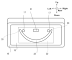
図12は、図7の取付面部15の変形例の説明図である。図12の取付面部15は、図1の自動車1の後方から見たものである。
図12において、円弧状の第二ビード部32は、図7または図9に示す場合より、上下方向に長く形成されている。
そして、図12の取付面部15には、日本国のライセンスプレート22が取り付けられている。
この場合であっても、取付面部15に形成される第二ビード部32は、第一ビード部31とともに、日本国のライセンスプレート22により外部から視認できないように覆われる。取付面部15に取り付けられた日本国のライセンスプレート22の周囲には、取付面部15についての平面状の部分のみが露出する。平板状のライセンスプレート22の周辺の視認状態は、取付面部15に対して第一ビード部31や第二ビード部32が形成されていない場合と同様になる。
Fig. 12 is an explanatory diagram of a modified example of the mounting surface portion 15 of Fig. 7. The mounting surface portion 15 of Fig. 12 is seen from the rear of the automobile 1 of Fig. 1.
In FIG. 12, the arc-shaped second bead portion 32 is formed longer in the up-down direction than in the case shown in FIG. 7 or FIG.
A Japanese license plate 22 is attached to the mounting surface portion 15 in FIG.
Even in this case, second bead portion 32 formed on mounting surface portion 15, together with first bead portion 31, is covered by Japanese license plate 22 so as not to be visible from the outside. Only the planar portion of mounting surface portion 15 is exposed around Japanese license plate 22 attached to mounting surface portion 15. The visibility of the periphery of flat license plate 22 is the same as when first bead portion 31 and second bead portion 32 are not formed on mounting surface portion 15.

上述した実施形態では、平面状の取付面部15には、第一ビード部31が1つで形成されている。
この他にもたとえば、平面状の取付面部15には、複数の第一ビード部31が形成されてもよい。複数の第一ビード部31は、たとえば左右一対の支持孔17の間に並べて設けられてよい。
また、上述した実施形態では、第一ビード部31は、取付面部15から後方へ向けて突出するように形成されている。
この他にもたとえば、第一ビード部31は、取付面部15から前方へ向けて突出するように形成されてもよい。
複数の第一ビード部31は、取付面部15から後方へ向けて突出するように形成されるものと、取付面部15から前方へ向けて突出するように形成されるものとを組み合わせて形成されてもよい。
In the above-described embodiment, the flat mounting surface portion 15 is formed with one first bead portion 31 .
Alternatively, for example, a plurality of first bead portions 31 may be formed on the planar mounting surface portion 15. The plurality of first bead portions 31 may be arranged side by side between a pair of left and right support holes 17, for example.
In the above-described embodiment, the first bead portion 31 is formed so as to protrude rearward from the mounting surface portion 15 .
Alternatively, for example, the first bead portion 31 may be formed so as to protrude forward from the mounting surface portion 15 .
The multiple first bead portions 31 may be formed by combining those that are formed so as to protrude rearward from the mounting surface portion 15 and those that are formed so as to protrude forward from the mounting surface portion 15.

上述した実施形態では、平面状の取付面部15には、円弧状の第二ビード部32が1つで形成されている。
この他にもたとえば、平面状の取付面部15には、複数の第二ビード部32が形成されてもよい。複数の第二ビード部32は、たとえば左右一対の支持孔17の上下に分けて設けられてよい。
また、上述した実施形態では、第二ビード部32は、取付面部15から前方へ向けて突出するように形成されている。
この他にもたとえば、第二ビード部32は、取付面部15から後方へ向けて突出するように形成されてもよい。
複数の第二ビード部32は、取付面部15から後方へ向けて突出するように形成されるものと、取付面部15から前方へ向けて突出するように形成されるものとを組み合わせて形成されてもよい。
In the embodiment described above, the flat mounting surface portion 15 is formed with one arc-shaped second bead portion 32 .
In addition, for example, a plurality of second bead portions 32 may be formed on the planar mounting surface portion 15. The plurality of second bead portions 32 may be provided separately above and below a pair of left and right support holes 17, for example.
In the above-described embodiment, the second bead portion 32 is formed so as to protrude forward from the mounting surface portion 15 .
Alternatively, for example, the second bead portion 32 may be formed so as to protrude rearward from the mounting surface portion 15 .
The multiple second bead portions 32 may be formed by combining those that are formed so as to protrude rearward from the mounting surface portion 15 and those that are formed so as to protrude forward from the mounting surface portion 15.

上述した実施形態では、平面状の取付面部15を補剛するために、第一ビード部31と第二ビード部32とを取付面部15に形成している。
これにより、平面状の取付面部15は、基本的に補剛され得るが、場合によってはさらなる補剛構造を組み合わせてもよい。
たとえば、取付面部15そのものに対して第一ビード部31または第二ビード部32を形成することに加えて、さらに、インナパネル11の一部を、アウタパネル12へ向けて伸ばして、アウタパネル12に連結してもよい。
この他にもたとえば、取付面部15そのものに対して第一ビード部31または第二ビード部32を形成することに加えて、さらに、インナパネル11とアウタパネル12との間にリンフォースを介在させてもよい。
In the above-described embodiment, the first bead portion 31 and the second bead portion 32 are formed on the planar mounting surface portion 15 in order to stiffen the mounting surface portion 15 .
This allows the planar mounting surface portion 15 to be basically stiffened, but in some cases, a further stiffening structure may be combined.
For example, in addition to forming the first bead portion 31 or the second bead portion 32 on the mounting surface portion 15 itself, a portion of the inner panel 11 may be extended toward the outer panel 12 and connected to the outer panel 12 .
Alternatively, for example, in addition to forming the first bead portion 31 or the second bead portion 32 on the mounting surface portion 15 itself, a reinforcement may be interposed between the inner panel 11 and the outer panel 12 .

1…自動車(車両)、2…車体、3…車室、4…後部開口、6…ヒンジ部材、7…ラッチ受け部材、8…ラッチ部材、10…リアゲート、11…インナパネル、12…アウタパネル、13…開口、14…横断カバー部材、15…取付面部、16…枠部、17…支持孔、18…リアガラス、19…リアランプ部材、20…弾性部材、21…固定部材、22,23…ライセンスプレート(表示部材)、31…第一ビード部、32…第二ビード部、33…両端部


DESCRIPTION OF SYMBOLS 1...Automobile (vehicle), 2...Vehicle body, 3...Vehicle compartment, 4...Rear opening, 6...Hinge member, 7...Latch receiving member, 8...Latch member, 10...Rear gate, 11...Inner panel, 12...Outer panel, 13...Opening, 14...Cross cover member, 15...Mounting surface portion, 16...Frame portion, 17...Support hole, 18...Rear glass, 19...Rear lamp member, 20...Elastic member, 21...Fixing member, 22, 23...License plate (display member), 31...First bead portion, 32...Second bead portion, 33...Both ends


Claims (5)

インナパネルとアウタパネルとが重ね合わされてなり、車両の後部開口に対して開閉可能に設けられる車両のリアゲートであって、
前記車両の表示部材を取り付けるために、前記アウタパネルに形成される取付面部と、
前記表示部材を前記取付面部に支持するために、前記取付面部に少なくとも左右一対にて形成される複数の支持部と、
前記アウタパネルの前記取付面部を変形させることにより、左右一対の前記支持部の間に形成される第一ビード部と、
前記アウタパネルの前記取付面部を変形させることにより、少なくとも左側の前記支持部から右側の前記支持部までの幅に渡って延在するように形成される第二ビード部と、
を有する、
車両のリアゲート。
A rear gate for a vehicle, which is formed by overlapping an inner panel and an outer panel and is provided so as to be capable of being opened and closed relative to a rear opening of the vehicle,
a mounting surface portion formed on the outer panel for mounting a display member of the vehicle;
A plurality of support portions formed on the mounting surface portion in at least one pair on the left and right sides in order to support the display member on the mounting surface portion;
a first bead portion formed between the pair of left and right support portions by deforming the mounting surface portion of the outer panel;
a second bead portion formed by deforming the mounting surface portion of the outer panel so as to extend at least across a width from the left support portion to the right support portion;
having
the tailgate of the vehicle.
前記第一ビード部は、左右一対の前記支持部の間において、前記アウタパネルの前記取付面部を変形させることにより、前記取付面部の外面から突出するように形成される、
請求項1記載の、車両のリアゲート。
The first bead portion is formed between the pair of left and right support portions so as to protrude from an outer surface of the mounting surface portion by deforming the mounting surface portion of the outer panel.
2. The vehicle rear gate according to claim 1.
前記第二ビード部は、前記アウタパネルの前記取付面部を変形させることにより、左右一対の前記支持部と前記車両の上下方向において並ぶように、円弧状に形成され、
前記第二ビード部についての円弧状の両端部は、前記取付面部において、左右一対の前記支持部についての左右両外側に位置する、
請求項1または2記載の、車両のリアゲート。
the second bead portion is formed in an arc shape so as to be aligned with the pair of left and right support portions in the up-down direction of the vehicle by deforming the mounting surface portion of the outer panel,
The second bead portion has two arcuate ends, each of which is located on the outer side of the pair of left and right support portions on the mounting surface portion.
3. A rear gate for a vehicle according to claim 1 or 2.
前記取付面部は、前記アウタパネルを変形させることにより、前記アウタパネルに形成されている、
請求項3記載の、車両のリアゲート。
The mounting surface portion is formed on the outer panel by deforming the outer panel.
4. A rear gate for a vehicle according to claim 3.
前記表示部材は、前記車両のライセンスプレートであり、
前記取付面部は、互いに外形が異なる複数のライセンスプレートを取り付け可能なサイズに形成され、
前記第二ビード部は、前記取付面部についての、複数の前記ライセンスプレートにより重複して覆われる範囲内に、形成される、
請求項4記載の、車両のリアゲート。


the display member is a license plate of the vehicle,
The mounting surface portion is formed to a size capable of mounting a plurality of license plates having different outer shapes,
The second bead portion is formed within a range of the mounting surface portion that is overlappingly covered by the plurality of license plates.
5. A rear gate for a vehicle according to claim 4.


JP2023148456A 2023-09-13 2023-09-13 Vehicle tailgate Pending JP2025041265A (en)

Priority Applications (2)

Application Number Priority Date Filing Date Title
JP2023148456A JP2025041265A (en) 2023-09-13 2023-09-13 Vehicle tailgate
US18/793,336 US20250083619A1 (en) 2023-09-13 2024-08-02 Rear gatefor vehicle

Applications Claiming Priority (1)

Application Number Priority Date Filing Date Title
JP2023148456A JP2025041265A (en) 2023-09-13 2023-09-13 Vehicle tailgate

Publications (1)

Publication Number Publication Date
JP2025041265A true JP2025041265A (en) 2025-03-26

Family

ID=94873307

Family Applications (1)

Application Number Title Priority Date Filing Date
JP2023148456A Pending JP2025041265A (en) 2023-09-13 2023-09-13 Vehicle tailgate

Country Status (2)

Country Link
US (1) US20250083619A1 (en)
JP (1) JP2025041265A (en)

Family Cites Families (7)

* Cited by examiner, † Cited by third party
Publication number Priority date Publication date Assignee Title
US6692057B2 (en) * 2001-10-12 2004-02-17 Suzuki Motor Corporation Latch attachment structure
JP4769229B2 (en) * 2007-06-12 2011-09-07 本田技研工業株式会社 Tailgate structure
JP5826736B2 (en) * 2012-11-21 2015-12-02 株式会社豊田自動織機 Vehicle door reinforcement structure
JP5772882B2 (en) * 2013-06-19 2015-09-02 トヨタ自動車株式会社 Vehicle back door
US9211850B2 (en) * 2013-07-09 2015-12-15 Edward J. Marko, JR. License plate frame and method of use
JP6565939B2 (en) * 2017-01-12 2019-08-28 トヨタ自動車株式会社 Vehicle panel structure
FR3127726B1 (en) * 2021-10-01 2025-07-18 Cie Plastic Omnium Se Motor vehicle opening fitted with an equipment support plate and a removable skin

Also Published As

Publication number Publication date
US20250083619A1 (en) 2025-03-13

Similar Documents

Publication Publication Date Title
US7591501B2 (en) Hatchback door structure for vehicles
US8132845B2 (en) Vehicle door structure
JP4366919B2 (en) Vehicle front deck structure
JP4710519B2 (en) Body front structure
EP3887205B1 (en) Vehicle trunk lid
JP6187495B2 (en) Upper back panel structure for vehicles
JP4924739B2 (en) Auto body structure
JP4092484B2 (en) Vehicle front structure
JP2011031701A (en) Cowl part structure of vehicle
JP4407599B2 (en) Body front support structure
JP2025041265A (en) Vehicle tailgate
JP7661728B2 (en) Vehicle front structure
JP2025041264A (en) Mounting structure for vehicle exterior components
JP5152637B2 (en) Structure of vehicle back door
JP2019018740A (en) Rear door structure for vehicles
JPH10244959A (en) Front pillar lower structure
JP2003165464A (en) Body front structure
JP2003276530A (en) Battery bracket mounting structure
JPH10236342A (en) Cab underframe structure
US20250083503A1 (en) Rear gate structure of vehicle
JP2012171569A (en) Door mirror attaching structure of vehicle door
JP2007196731A (en) Structure around the glove box in the vehicle compartment
JP2003182641A (en) Cab structure of vehicle
JP2018012502A (en) Reinforcement structure of resin back door
KR20050011521A (en) Reinforcing structure of dash panel for automobile

Legal Events

Date Code Title Description
RD02 Notification of acceptance of power of attorney

Free format text: JAPANESE INTERMEDIATE CODE: A7422

Effective date: 20250530