JP2025041264A - Mounting structure for vehicle exterior components - Google Patents
Mounting structure for vehicle exterior components Download PDFInfo
- Publication number
- JP2025041264A JP2025041264A JP2023148455A JP2023148455A JP2025041264A JP 2025041264 A JP2025041264 A JP 2025041264A JP 2023148455 A JP2023148455 A JP 2023148455A JP 2023148455 A JP2023148455 A JP 2023148455A JP 2025041264 A JP2025041264 A JP 2025041264A
- Authority
- JP
- Japan
- Prior art keywords
- outer panel
- vehicle
- portions
- exterior member
- width direction
- Prior art date
- Legal status (The legal status is an assumption and is not a legal conclusion. Google has not performed a legal analysis and makes no representation as to the accuracy of the status listed.)
- Pending
Links
Images

Classifications
-
- B—PERFORMING OPERATIONS; TRANSPORTING
- B60—VEHICLES IN GENERAL
- B60R—VEHICLES, VEHICLE FITTINGS, OR VEHICLE PARTS, NOT OTHERWISE PROVIDED FOR
- B60R11/00—Arrangements for holding or mounting articles, not otherwise provided for
Landscapes
- Engineering & Computer Science (AREA)
- Mechanical Engineering (AREA)
- Vehicle Interior And Exterior Ornaments, Soundproofing, And Insulation (AREA)
Abstract

【課題】車両の外面を構成するアウタパネルの外面に外装部材を取り付けることに起因する異音の発生を抑制する。
【解決手段】車両の外面を構成するアウタパネルと、アウタパネルの外面に取り付けられてアウタパネルに支持される外装部材と、を有する車両の外装構造は、外装部材をアウタパネルに取り付けるために、アウタパネルに形成される複数の支持部と、アウタパネルについての、アウタパネルに取り付けられた外装部材が重なる重なり部分に形成される複数のビード部と、を有する。複数のビード部は、アウタパネルについての重なり部分において、複数の支持部の間に介在して、車両の内側へ向けて凸となるように形成される。
【選択図】図5
The present invention provides a vehicle exterior panel that suppresses the generation of abnormal noise caused by attaching an exterior member to the outer surface of an outer panel that constitutes the exterior of a vehicle.
[Solution] A vehicle exterior structure having an outer panel that constitutes the exterior surface of the vehicle and an exterior member attached to the outer surface of the outer panel and supported by the outer panel has a plurality of support parts formed on the outer panel to attach the exterior member to the outer panel, and a plurality of bead parts formed on the outer panel at overlapping portions where the exterior member attached to the outer panel overlaps. The plurality of bead parts are interposed between the plurality of support parts in the overlapping portions of the outer panel and are formed so as to be convex toward the inside of the vehicle.
[Selected figure] Figure 5
Description
本発明は、車両の外装部材の取付構造に関する。 The present invention relates to a mounting structure for vehicle exterior components.
自動車といった車両では、特許文献1のように車両の車室などを画成するために、車両の外面を構成するアウタパネルが用いられる。特許文献1のアウタパネルは、インナパネルと重ね合わされることにより、車両の後部開口に対して開閉可能に設けられる車両のリアゲートを構成している。リアゲートは、車両の荷室または車室についての後方を画成するものである。
特許文献2の車両のリアゲートでは、アウタパネルと並べて、アウタパネルの左右両側に、左右一対のテールランプ部材を設けている。特許文献2では、左右一対のテールランプ部材は、リアゲートのインナパネルに対して取り付けられている。
特許文献3の車両のリアゲートでは、ガーニッシュ部材を、アウタパネルの上部外面に取り付けている。
In vehicles such as automobiles, an outer panel that constitutes the exterior of the vehicle is used to define the vehicle interior, as in
In the vehicle rear gate of
In the vehicle rear gate of
ところで、特許文献3のようにアウタパネルの外面にガーニッシュ部材などの外装部材を取り付ける場合、アウタパネル単体では実現が容易ではない車両の外観の意匠を提供することが可能になる。たとえば、特許文献3のようにリアゲートの上下方向の中央部を外に突き出たような意匠を提供することが可能になる。このような意匠は、特許文献1や特許文献2のリアゲートでは提供されない、好ましい1つの意匠となり得る。
しかしながら、特許文献3のようにアウタパネルの外面に外装部材を取り付けると、そのことに起因する所謂こもり音などの異音が発生することがある。たとえば、車両のアイドリング動作中や、リアゲートの開閉の際に、所謂こもり音などの異音が発生することがある。そして、このような異音は、車両の乗員に可聴され、乗員に違和感を与えてしまう可能性がある。
特に、特許文献3のようにアウタパネルの外面に外装部材を取り付ける場合、リアゲートの質量が前記外装部材の取り付け部分において部分的に増加したり、外装部材が前記アウタパネルの上で振動したり、する可能性がある。これらに起因して、所謂こもり音などの異音が発生し易くなると予想される。
Incidentally, when an exterior member such as a garnish member is attached to the outer surface of the outer panel as in
However, when an exterior member is attached to the outer surface of the outer panel as in
In particular, when an exterior member is attached to the outer surface of the outer panel as in
このように車両では、車両の外面を構成するアウタパネルの外面に外装部材を取り付けることに起因する異音の発生を抑制して、該異音が車両の乗員により可聴されることが起き難くすることが求められている。 In this way, there is a need to suppress the generation of abnormal noise caused by attaching exterior members to the outer surface of the outer panel that constitutes the exterior of the vehicle, and to make it difficult for the abnormal noise to be heard by vehicle occupants.
本発明の実施の一形態に係る車両の外装部材の取付構造は、車両の外面を構成するアウタパネルと、前記アウタパネルの外面に取り付けられて前記アウタパネルに支持される外装部材と、を有する車両の外装構造であって、前記外装部材を前記アウタパネルに取り付けるために、前記アウタパネルに形成される複数の支持部と、前記アウタパネルについての、前記アウタパネルに取り付けられた前記外装部材が重なる重なり部分に形成される複数のビード部と、を有し、複数の前記ビード部は、前記アウタパネルについての前記重なり部分において、複数の前記支持部の間に介在して、前記車両の内側へ向けて凸となるように形成される、ものである。 The mounting structure for an exterior member of a vehicle according to one embodiment of the present invention is an exterior structure for a vehicle having an outer panel that constitutes the outer surface of the vehicle, and an exterior member that is attached to the outer surface of the outer panel and supported by the outer panel, and includes a plurality of support parts formed on the outer panel in order to mount the exterior member to the outer panel, and a plurality of bead parts formed in overlapping portions of the outer panel where the exterior member attached to the outer panel overlaps, and the plurality of bead parts are interposed between the plurality of support parts in the overlapping portions of the outer panel and are formed so as to be convex toward the inside of the vehicle.
本発明では、車両の外面を構成するアウタパネルに対して外装部材が取り付けられ、外装部材が、アウタパネルにより支持される。このため、本発明では、アウタパネルに、外装部材をアウタパネルに取り付けるための複数の支持部を形成する。また、本発明では、さらに、アウタパネルについての、アウタパネルに取り付けられる外装部材が重なる重なり部分に、複数のビード部を形成する。複数のビード部は、アウタパネルについての重なり部分において、複数の支持部の間に介在するように形成される。これにより、車両の外面を構成するアウタパネルは、車両の意匠のための形状に形成されているとしても、アウタパネルの重なり部分に形成される複数の支持部の間は、複数のビード部により補剛され得る。
その結果、本発明では、アウタパネルに形成される複数の支持部の相互距離や相対的な位置は、アウタパネルに取り付けられる外装部材がアウタパネルの上で振動したり、リアゲートの質量が外装部材を取り付けることにより部分的に増加したり、するとしても、変化し難くなる。基本的な形状が車両の意匠のための形状とされるアウタパネルは、複数のビード部により補剛されている複数の支持部により、それに取り付けられる外装部材を、アウタパネルの上で振動し難くなるように支持することができる。
また、本発明では、アウタパネルの重なり部分に形成される複数の支持部の間には、単一のビード部を形成するのではなく、複数のビード部を形成する。ビード部を複数で形成することにより、各ビード部は、アウタパネルの重なり部分のサイズなどに影響されることなく所望の形状やサイズに、たとえば外装部材が取り付けられているアウタパネルにおいて発生する所謂こもり音などの異音の抑制することが期待できる形状やサイズに形成することが可能になる。このようにビード部を複数で形成することにより、本発明では、外装部材が取り付けられているアウタパネルにおいて、たとえば外装部材の振動にしたがってアウタパネルが振動することにより発生し得る所謂こもり音などの異音を、減衰することが期待できる。
このように、本発明では、アウタパネルの上で、アウタパネルに取り付けて支持されている外装部材が振動することに起因するこもり音などの異音の発生や、その異音にしたがってアウタパネルが振動してしまうこと、などを抑制することが期待できる。車両の乗員は、外装部材が取り付けられているアウタパネルから発生されるこれらの異音を可聴し難くなる、ことが期待できる。
In the present invention, an exterior member is attached to an outer panel that constitutes the exterior surface of a vehicle, and the exterior member is supported by the outer panel. For this reason, in the present invention, a plurality of support portions for attaching the exterior member to the outer panel are formed in the outer panel. Furthermore, in the present invention, a plurality of bead portions are further formed in an overlapping portion of the outer panel where the exterior member to be attached to the outer panel overlaps. The plurality of bead portions are formed so as to be interposed between the plurality of support portions in the overlapping portion of the outer panel. As a result, even if the outer panel that constitutes the exterior surface of the vehicle is formed in a shape for the vehicle design, the spaces between the plurality of support portions formed in the overlapping portion of the outer panel can be stiffened by the plurality of bead portions.
As a result, in the present invention, the mutual distances and relative positions of the multiple support parts formed on the outer panel are unlikely to change even if the exterior member attached to the outer panel vibrates on the outer panel or the mass of the rear gate is partially increased by attaching the exterior member. The outer panel, whose basic shape is determined based on the design of the vehicle, is able to support the exterior member attached thereto by the multiple support parts stiffened by the multiple bead parts so that the exterior member is unlikely to vibrate on the outer panel.
Furthermore, in the present invention, instead of forming a single bead portion between the multiple support portions formed in the overlapping portion of the outer panel, multiple bead portions are formed. By forming multiple bead portions, each bead portion can be formed into a desired shape and size without being affected by the size of the overlapping portion of the outer panel, for example, into a shape and size that can be expected to suppress abnormal noise such as so-called booming noise generated in the outer panel to which an exterior member is attached, for example. By forming multiple bead portions in this way, in the present invention, it is expected that abnormal noise such as so-called booming noise that can be generated in the outer panel to which an exterior member is attached due to vibration of the outer panel in accordance with vibration of the exterior member can be attenuated.
In this way, the present invention is expected to suppress the generation of abnormal noises such as muffled noises caused by vibrations of the exterior member attached to and supported on the outer panel, and the vibration of the outer panel due to such abnormal noises, etc. It is expected that vehicle occupants will be less likely to hear these abnormal noises generated from the outer panel to which the exterior member is attached.
しかも、本発明では、外装部材を、異音が発生し難くなるようにアウタパネルに対して取り付けることができる。このため、本発明では、アウタパネルの意匠、および外装部材の意匠について、これらの意匠を制限することにより異音の発生を抑制する必要性が低下し、これらの意匠について高い自由度を提供することが可能になる。 Moreover, in the present invention, the exterior member can be attached to the outer panel in a way that makes it difficult for abnormal noise to occur. Therefore, in the present invention, there is less need to restrict the design of the outer panel and the exterior member to suppress the generation of abnormal noise, and it is possible to provide a high degree of freedom in the design of these.
さらに、本発明では、アウタパネルについての重なり部分に形成される複数のビード部は、車両の内側へ向けて凸となるように形成される。これにより、アウタパネルの重なり部分には、該重なり部分の外面に取り付けられる外装部材へ向けて不要に凸となる凸部が形成されない。外装部材についての、アウタパネルの重なり部分への取り付け性は、複数のビード部により阻害されることがない。 Furthermore, in the present invention, the multiple bead portions formed in the overlapping portion of the outer panel are formed so as to be convex toward the inside of the vehicle. As a result, no convex portions are formed in the overlapping portion of the outer panel that are unnecessarily convex toward the exterior member attached to the outer surface of the overlapping portion. The multiple bead portions do not impede the attachment of the exterior member to the overlapping portion of the outer panel.
以下、本発明の実施形態を、図面に基づいて説明する。 The following describes an embodiment of the present invention with reference to the drawings.
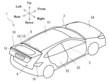
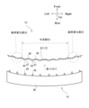
図1は、本発明の実施形態に係る自動車1の斜視図である。図1において、自動車1のリアゲート10は、閉じている。
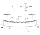
図2は、図1の自動車1のリアゲート10を開いた状態を示す図である。
図1以降の図面において、前後左右上下の各方向は、図1のようにリアゲート10を閉じた状態について示している。また、自動車1の車幅方向は、左右方向のことをいう。
Fig. 1 is a perspective view of an
FIG. 2 is a diagram showing the
In the drawings from Fig. 1 onwards, the front, rear, left, right, top and bottom directions are shown in a state where the
図1の自動車1は、車両の一例である。自動車1は、車室3が画成される車体2を有する。自動車1は、車室3に対して乗員が乗降するための複数のドア52とともに、車室3の後部である荷室にアクセスするためのリアゲート10、を有する。リアゲート10は、その上縁部分が一対のヒンジ部材6により、車体2のルーフ51に取り付けられている。リアゲート10は、図1および図2に示すように、後部開口4に対して開閉可能である。
リアゲート10を開くと、図2に示すように、自動車1の車体2に後部開口4が現れる。乗員は、後部開口4から荷室の荷物を出し入れすることができる。また、乗員は、開いているリアゲート10を引き下げる。これにより、リアゲート10は、図1のように閉じる。自動車1の車体2の後部開口4は、閉塞される。荷室の荷物は、後部開口4から脱落しない。
次に、このような自動車1の外装部材の取付構造について、リアゲート10に横断ガーニッシュ部材14を取り付ける場合を例に説明する。
なお、図1および図2に示す自動車1の外観は、リアゲート10の外面を含めて、曲面形状を多用した好ましい意匠になっている。リアゲート10は、自動車1のその他の部分と調和し、自動車1の意匠は全体的にまとまりのあるものとなっている。
An
When the
Next, the mounting structure for the exterior member of the
1 and 2 has a pleasing design that makes extensive use of curved shapes, including the outer surface of the
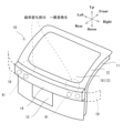
図3は、図1のリアゲート10の模式的な斜視図である。
図3に示すように、リアゲート10は、自動車1の後側の外面を構成するアウタパネル12と、アウタパネル12の内側に重ね合わされるインナパネル11と、を有する。また、アウタパネル12の外面には、横断ガーニッシュ部材14が取り付けられている。
FIG. 3 is a schematic perspective view of the
3, the
インナパネル11とアウタパネル12とは、自動車1の後部開口4を閉塞できるように、図3に例示するように略四角形の外形の鋼板を用いて、後部開口4に沿った外形に形成される。特に、アウタパネル12は、自動車1の外表面に露出して、自動車1の意匠を構成する。インナパネル11とアウタパネル12とは、一般的にプレス加工により所望の押し出し形状に成形される。インナパネル11の外周縁部とアウタパネル12の外周縁部とは重ね合わされ、接着剤により貼りあわされてよい。アウタパネル12の外周縁部は、インナパネル11の外周縁部の外側で折り曲げられて、折り曲げられた部分により、インナパネル11の外周縁部を把持してよい。このような構造で重ね合わされるインナパネル11とアウタパネル12とは、リアゲート10に求められている基本的な剛性を得ることが可能である。一対のヒンジ部材6は、基本的に、略四角形の鋼板のインナパネル11の上縁部に取り付けられてよい。これにより、一対のヒンジ部材6は、リアゲート10を閉じた状態で、図1に示すように、アウタパネル12により覆うことができる。
The
リアゲート10の上部には、略四角形の外形の鋼板を押し出し形状に成形してなるインナパネル11の上部とアウタパネル12の上部とを貫通させることにより、開口13が形成される。リアゲート10の上部の開口13には、リアガラス18が、たとえばアウタパネル12の外側から嵌め込まれる。なお、インナパネル11とアウタパネル12とは、開口13の周囲においても重ね合わされ、接着剤により貼りあわされてよい。また、アウタパネル12の開口縁部は、インナパネル11の開口縁部の内側で折り曲げられて、折り曲げられた部分によりインナパネル11の開口縁部を把持してよい。これにより、インナパネル11とアウタパネル12とは、それらの上部に大きな開口13が形成されているとしても、それらの上部の形状を保つための最低限の剛性を得ることが可能になる。
An
リアゲート10のアウタパネル12の下部には、略四角形の平板状のライセンスプレートを取り付けるためのプレート取付部15が形成される。プレート取付部15は、後述するように、自動車1が登録される複数の国でのライセンスプレートが取り付け可能となるように、複数種類のライセンスプレートより大きい平面状に形成するとよい。また、各国の法規では、ライセンスプレートを取り付けるためのプレート取付部15は、ライセンスプレートの視認性の確保などのために、基本的に平面にすることが求められている。なお、特定の国では、発光機能を有するライセンスプレートが法規において許容されている国がある。また、プレート取付部15には、将来的には、自動運転状態や速度といった走行状態を、点灯状態の変化により表示可能な表示部材が取り付けられる可能性がある。
A
プレート取付部15は、たとえばアウタパネル12をプレス加工により押し出し成形することにより、アウタパネル12に形成されてよい。本実施形態のプレート取付部15の周囲には、プレス加工での押し出し成形により湾曲してなる枠部が形成されている。そして、プレート取付部15は、アウタパネル12についてのプレート取付部15以外の残部と比べて、自動車1の前方向へ窪んだ状態で、アウタパネル12に形成されている。プレート取付部15は、その周囲に湾曲してなる枠部が形成されることにより、アウタパネル12を補剛するように機能し得る。このようなプレート取付部15が形成されることにより、アウタパネル12は、その全体において振動し難くなることが期待できる。
The
リアゲート10のアウタパネル12についての、リアガラス18のための開口13とプレート取付部15との間である、上下方向の中央部には、横断ガーニッシュ部材14が設けられる。横断ガーニッシュ部材14は、アウタパネル12の上下方向の中央部において、アウタパネル12についての自動車1の車幅方向において全幅に渡って、横長に設けられる。アウタパネル12の外面に取り付けられる横長の横断ガーニッシュ部材14は、図1に示すように、左右のリアランプ部材19の間に渡るように設けられ、左右のリアランプ部材19と一体的なまとまりのある直線状の意匠を形成する。なお、横断ガーニッシュ部材14には、左右のリアランプ部材19と連動して点灯可能な点灯部材41や、プレート取付部15に取り付けられるライセンスプレートを照らすための不図示の点灯部材41などが設けられてよい。
A
ところで、このようにアウタパネル12の外面に横断ガーニッシュ部材14を取り付ける場合、アウタパネル12の単体では実現が容易ではない自動車1の外観の意匠を提供することが可能になる。図3では、傾斜するリアガラス18の下側にあるリアゲート10の下部において、横断ガーニッシュ部材14が後方に突き出る意匠となっている。このような意匠は、アウタパネル12をプレス加工により押し出し成形するだけでは、良好な形状とすることが難しい。このような意匠は、自動車1の意匠として、好ましい1つの意匠である。
しかしながら、アウタパネル12の外面に横断ガーニッシュ部材14などの外装部材を取り付けると、そのことに起因する所謂こもり音などの異音が発生することがある。たとえば、自動車1のアイドリング動作中や、リアゲート10の開閉の際に、所謂こもり音などの異音が発生することがある。そして、このような異音は、自動車1の乗員に可聴され、乗員に違和感を与えてしまう可能性がある。
特に、図3のようにアウタパネル12の外面に横断ガーニッシュ部材14を取り付ける場合、リアゲート10の質量が横断ガーニッシュ部材14の取り付け部分において部分的に増加したり、横断ガーニッシュ部材14がアウタパネル12の上で振動したり、する可能性がある。
また、図3のようにアウタパネル12の左右方向の両側部の曲率が、左右方向の中央部の曲率より大きくなるように形成されている場合、その曲率が変化する部分において、アウタパネル12の上で振動する横断ガーニッシュ部材14がアウタパネル12に当たり易くなる。
これらの原因により、アウタパネル12の外面に横断ガーニッシュ部材14などの外装部材を取り付けると、所謂こもり音などの異音が発生し易くなると予想される。
Incidentally, when the
However, when an exterior member such as the
In particular, when the
Furthermore, if the curvature of both left-right side portions of the
For these reasons, it is expected that when an exterior member such as the
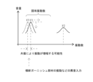
図4は、図3の模式的なリアゲート10の一例の振動特性を説明する、振動数の特性図である。
図4の横軸は、振動数である。縦軸は、音量である。
FIG. 4 is a frequency characteristic diagram illustrating the vibration characteristics of an example of the schematic
The horizontal axis of Fig. 4 is the vibration frequency, and the vertical axis is the volume.
そして、図4に示すように、アウタパネル12は、その外形などに応じた固有振動数を有する。図4には、アウタパネル12の固有振動数として、第一固有振動数F1と、第二固有振動数F2と、が示されている。
また、図4には、インナパネル11の固有振動数として、第三固有振動数F3が示されている。
図3において、アウタパネル12と、インナパネル11とは、略同じサイズの外形に形成されている。この場合、アウタパネル12の第一固有振動数F1と、インナパネル11の第三固有振動数F3とは、図4に示すように、近接し易い。
As shown in Fig. 4, the
FIG. 4 also shows a third natural frequency F3 as a natural frequency of the
3, the
そして、このようにアウタパネル12の固有振動数とインナパネル11の固有振動数とが近接する場合、アウタパネル12とインナパネル11とは共振し易い。
また、外装部材としての横断ガーニッシュ部材14は、このようなアウタパネル12の外面に取り付けられる。横断ガーニッシュ部材14が、アウタパネル12の上で、共振し得る固有周波数の成分を含むように振動すると、横断ガーニッシュ部材14の振動に起因するこもり音などの異音が、アウタパネル12とインナパネル11との共振により増幅されたり、残響したりし易くなる。増幅された異音や残響する異音は、自動車1の乗員に可聴され易くなる。
また、アウタパネル12の外面に取り付けられる外装部材としての横断ガーニッシュ部材14は、自動車1のアイドリング動作中や、リアゲート10の開閉の際に振動し易い。
When the natural frequency of the
Furthermore, a
In addition, the
このように自動車1では、自動車1の外面を構成するアウタパネル12の外面に外装部材としての横断ガーニッシュ部材14を取り付けることに起因する異音の発生を抑制して、自動車1の乗員に可聴され難くすることが求められている。
In this way, in
図5は、図3の模式的なリアゲート10のアウタパネル12の構造を、後方から見た説明図である。
アウタパネル12は、略四角形の外形を有する鋼板をプレス加工により押し出し成形することにより、図5に示す形状に形成され得る。
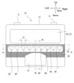
図6は、図5のリアゲート10のアウタパネル12のA-A横断面図である。図6には、アウタパネル12の外面に取り付けられる外装部材としての横断ガーニッシュ部材14とともに、アウタパネル12の重なり部分42の構造が示されている。
図7は、図6の横断ガーニッシュ部材14を、アウタパネル12の外面に取り付けた状態を示す説明図である。
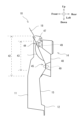
図8は、図5のリアゲート10のアウタパネル12のB-B縦断面図である。図8には、アウタパネル12の外面に取り付けられている横断ガーニッシュ部材14、リアガラス18などが併せて示されている。
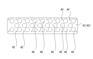
FIG. 5 is an explanatory diagram showing the structure of the
The
Fig. 6 is a cross-sectional view taken along line A-A of the
FIG. 7 is an explanatory diagram showing a state in which the
Fig. 8 is a vertical cross-sectional view taken along line BB of the
略四角形の外形のアウタパネル12の上部には、リアガラス18をはめ込むための開口13が形成される。
略四角形の外形のアウタパネル12の下部についての左右方向の中央部分には、平面状のプレート取付部15が形成される。平面状のプレート取付部15には、平板状のライセンスプレートが取り付けられる。
そして、略四角形の外形のアウタパネル12についての上下方向の中央部には、図5においてハッチングを付して示すように、アウタパネル12に取り付けられた横断ガーニッシュ部材14が重なる重なり部分42が設けられている。重なり部分42は、アウタパネル12についての上下方向の中央部において、アウタパネル12についての左右方向の全幅に渡って設けられている。
An
A planar
5, an overlapping
また、アウタパネル12の重なり部分42には、外装部材としての横断ガーニッシュ部材14を、アウタパネル12に取り付けて支持するための外装取付部43が設けられる。アウタパネル12の外装取付部43は、アウタパネル12についての上下方向の中央部において、アウタパネル12についての左右方向の略全幅に渡って設けられる。
In addition, an
重なり部分42の内側に設けられる横断ガーニッシュ部材14をアウタパネル12に支持するための外装取付部43には、複数の上側支持孔44、複数の下側支持孔45、および、複数のビード部46、が形成される。
The
複数の上側支持孔44と、複数の下側支持孔45とは、横断ガーニッシュ部材14をアウタパネル12に支持するための複数の支持孔である。横断ガーニッシュ部材14は、図6から図8に示すように、ガーニッシュ本体48のアウタパネル12に取り付けられる面に、複数の上側支持孔44および複数の下側支持孔45の各々に挿入可能な複数の弾性ピン49を有する。そして、図7および図8に示すように、複数の弾性ピン49が複数の上側支持孔44と複数の下側支持孔45とに挿入されることにより、横断ガーニッシュ部材14は、アウタパネル12の外面の上に取り付けられて、アウタパネル12に支持される。これにより、複数の上側支持孔44と、複数の下側支持孔45とは、横断ガーニッシュ部材14をアウタパネル12に取り付けるために、アウタパネル12に形成される複数の支持部として機能する。
また、アウタパネル12の外面の上に取り付けられる状態で、アウタパネル12との間に隙間を生じないように、横断ガーニッシュ部材14についてのアウタパネル12との取付面は、アウタパネル12の外形にならった湾曲した形状とされている。
The upper support holes 44 and the lower support holes 45 are support holes for supporting the
In addition, in order to prevent a gap from occurring between the
複数の下側支持孔45は、図8に示すように、アウタパネル12についての重なり部分42を後方に向けて横長の直線状に突出させるように造形した部分に形成される。複数の下側支持孔45は、図5に示すように、重なり部分42の内側の外装取付部43において、自動車1の車幅方向の全幅に渡って、直線状に配列して形成される。
As shown in FIG. 8, the multiple lower support holes 45 are formed in the overlapping
複数の上側支持孔44は、図8に示すように、複数の凸状部47の各々の頂部に形成される。複数の凸状部47は、重なり部分42の内側の外装取付部43において、自動車1の車幅方向の全幅に渡って、直線状に配列して形成される。この場合、複数の上側支持孔44は、重なり部分42の内側の外装取付部43において、自動車1の車幅方向の全幅に渡って、直線状に配列されることになる。複数の凸状部47は、アウタパネル12についての重なり部分42を、自動車1の後方に向けて突出するように凸状に変形させて形成されている。このような複数の凸状部47は、プレス加工による押し出し成形により、アウタパネル12に造形することができる。
The upper support holes 44 are formed at the top of each of the multiple
このような複数の上側支持孔44は、図5に示すように、アウタパネル12の重なり部分42において、車幅方向に延在する横断ガーニッシュ部材14の上縁に沿うように、車幅方向に並ぶ。
また、複数の下側支持孔45は、アウタパネル12の重なり部分42において、車幅方向に延在する横断ガーニッシュ部材14の下縁に沿うように、車幅方向に並ぶ。
As shown in FIG. 5, the multiple upper support holes 44 are aligned in the vehicle width direction in the overlapping
Further, the multiple lower support holes 45 are aligned in the vehicle width direction in the overlapping
複数のビード部46は、アウタパネル12の重なり部分42において、車幅方向に並べて形成される。
図5において、複数のビード部46は、基本的に、車幅方向に並ぶ複数の上側支持孔44と、車幅方向に並ぶ複数の下側支持孔45との間において、これらの間に介在するように、車幅方向に並べて形成される。
また、複数のビード部46は、基本的に、複数の凸状部47に形成される複数の上側支持孔44との間で、交互となるように並べて形成される。これにより、複数のビード部46は、車幅方向に並ぶ複数の上側支持孔44の間に介在することになる。
この場合、複数の上側支持孔44は、複数の基準支持孔として機能する。
The
In Figure 5, the
Furthermore, the
In this case, the multiple upper support holes 44 function as multiple reference support holes.
なお、複数のビード部46は、図5とは異なる個数で、アウタパネル12の重なり部分42において車幅方向に並べて形成されてよい。
アウタパネル12の重なり部分42に複数のビード部46を形成することにより、アウタパネル12の剛性や固有振動数は、変化し得る。
図4において横矢印で示すように、アウタパネル12の固有振動数は、アウタパネル12の重なり部分42に複数のビード部46を形成することにより変化し得る。
また、図4において縦矢印で示すように、固有振動数に起因する音量は、アウタパネル12の重なり部分42に複数のビード部46を形成することにより変化し得る。
ただし、この固有振動数の変化の程度は、アウタパネル12の重なり部分42に形成するビード部46の個数や、重なり部分42での配置などに応じて異なるものになる、と予想される。
また、アウタパネル12の固有振動数そのものも、アウタパネル12のサイズや形状などに応じて異なるものになる、と予想される。
アウタパネル12の重なり部分42に形成する複数のビード部46は、自動車1の基本的な意匠などの外形に応じて、望ましい個数が変化する。
このため、アウタパネル12の重なり部分42に形成するビード部46の個数は、自動車1のアウタパネル12や横断ガーニッシュ部材14の基本的なサイズや形状に応じて異なるものとすることが望ましい。
たとえば、自動車1の外形の意匠によっては、複数のビード部46は、図5とは異なり、図5の1つ置きに形成することが望ましい可能性もある。また、アウタパネル12の車幅方向の両端部分に集中して形成したり、アウタパネル12の車幅方向の中央部分に集中して形成したり、することが望ましくなる可能性もある。
この他にもたとえば図6に示すように、アウタパネル12の曲率変化部分について、複数のビード部46を集中的に形成することも考えられる。また、アウタパネル12の左右の曲率変化部分の間に、複数のビード部46を集中的に形成することも考えられる。
これらのように複数のビード部46が間欠的に並べられる場合でも、複数のビード部46は、図5に例示するように、複数の基準支持孔としての複数の上側支持孔44との間で交互配列となる並びを基本にして形成するのが望ましいと考えられる。
なお、複数のビード部46の交互配列の基準となる複数の基準支持孔は、複数の下側支持孔45であってもよい。また、図5とは異なり、複数の上側支持孔44と複数の下側支持孔45とが上下に並ぶ配列である場合、複数のビード部46は、上下の複数の支持孔44,45との間で交互配列となる並びを基本として形成されてもよい。
Note that the
By forming a plurality of
As indicated by the horizontal arrow in FIG. 4 , the natural frequency of the
As indicated by the vertical arrows in FIG. 4 , the sound volume caused by the natural frequency can be changed by forming a plurality of
However, it is expected that the degree of change in this natural frequency will differ depending on the number of
In addition, it is expected that the natural frequency of the
The desired number of the
For this reason, it is desirable that the number of
For example, depending on the exterior design of the
6, for example, it is also possible to form a plurality of
Even when the
The multiple reference support holes that serve as a reference for the alternating arrangement of the
ビード部46は、図8に示すように、自動車1の内側へ向けて凸となるように形成される。ここで、リアゲート10のアウタパネル12は、自動車1の後側に設けられるものであるから、自動車1の内側とは、自動車1の前側を意味する。
また、ビード部46は、図5に示すように、真球形状の一部である球欠形状に形成される。
このようなビード部46は、アウタパネル12の重なり部分42を、プレス加工による押し出し成形により変形させることにより形成することが可能である。
このようにビード部46は、真球形状の一部である球欠形状に形成される。これにより、ビード部46は、それに対して入力される振動や応力について、その入力方向によらずに変形し難いものになり得る。
なお、ビード部46は、楕円球形状の一部である球欠形状に形成されてもよい。この場合でも、ビード部46は、それに対して入力される振動や応力について、その入力方向によらずに変形し難いものになり得る。
これに対し、仮にたとえばビード部46が、四角形などの多角形形状に形成されている場合、ビード部46は、それに対して入力される振動や応力について、その入力方向によっては変形し易くなる可能性がある。
8, the
As shown in FIG. 5, the
Such a
In this way, the
The
In contrast, if the
また、このように真球形状の一部である球欠形状であるビード部46は、アウタパネル12を含むリアゲート10から発生する異音の振動数に応じた個数、サイズ、深さに形成してよい。
たとえば図3のアウタパネル12の第一固有振動数F1を抑制しようとする場合、球欠形状のビード部46は、その直径Dまたは半径D/2が、第一固有振動数F1のたとえば逓倍に相当する長さに、または逓倍分の一に相当する長さに形成してよい。これにより、第一固有振動数F1での音量に対して、それを抑制する効果が得られることが期待し得る。アウタパネル12に形成するビード部46の個数、サイズ、深さを最適化することにより、アウタパネル12の固有振動数を変化させて、乗員に可聴されてしまう所謂こもり音を改善することが期待できる。アウタパネル12に形成するビード部46の個数、サイズ、深さは、たとえばそれらを互いに異なるようにした複数のアウタパネル12を形成して、異音の発生状況を評価することにより、良好化することが可能である。
ビード部46を複数で形成することにより、各ビード部46は、アウタパネル12の重なり部分42のサイズなどに影響されることなく所望の形状やサイズに形成することが可能になる。各ビード部46は、たとえば外装部材としての横断ガーニッシュ部材14が取り付けられているアウタパネル12において発生する所謂こもり音などの異音を抑制することが期待できる形状やサイズに形成することが可能になる。このようにビード部46を複数で形成することにより、本実施形態では、外装部材としての横断ガーニッシュ部材14が取り付けられているアウタパネル12において、たとえば外装部材の振動にしたがってアウタパネル12が振動することにより発生し得る所謂こもり音などの異音を、減衰することが期待できる。
Furthermore, the
For example, when suppressing the first natural frequency F1 of the
By forming a plurality of
また、図5に示すように、ビード部46は、球欠形状の上端部分が部分的に、隣接する一対の上側支持孔44についての一対の凸状部47の間に介在している。
これにより、球欠形状のビード部46は、図8に示すように、上側支持孔44と同じ高さ位置から、下方へ向けて延在するように形成されることになる。
外装取付部43についての、上側支持孔44から下側支持孔45までの範囲は、上側支持孔44と同じ高さ位置から下方へ向けて延在する球欠形状のビード部46により、折れ曲がり難くなる。
外装取付部43は、図8の紙面内で折れ曲がるように変形し難くなる。
As shown in FIG. 5 , the
As a result, the
The area from the
The
このように複数のビード部46は、アウタパネル12の図5での左右方向である車幅方向および上下方向においてともに変形し難くなるように、外装取付部43を補剛することかできる。
その結果、複数のビード部46は、図7のように、アウタパネル12に対して外装部材としての横断ガーニッシュ部材14が取り付けられた状態において、横断ガーニッシュ部材14がアウタパネル12の外面の上で振動するとしても、その振動により外装取付部43が変形することを抑制し得る。複数のビード部46は、アウタパネル12が外装取付部43とともに振動したり変形したりしてしまうことを抑制することができる。
たとえば、図7に示すように曲率変化部分を有するアウタパネル12の上で横断ガーニッシュ部材14が振動しようとしても、曲率変化部分に形成されている複数の支持孔44,45の間がビード部46により補剛されているため、アウタパネル12が曲率変化部分において変形するようなことが起き難くなる。その結果、アウタパネル12の曲率変化部分での複数の支持孔44,45による横断ガーニッシュ部材14の支持状態が変化し難くなる。横断ガーニッシュ部材14は、曲率変化部分においてアウタパネル12との間隔を変化させるように大きく振動し難くなる。
In this manner, the plurality of
7 , even if the
For example, even if the
以上のように、本実施形態では、自動車1の外面を構成するアウタパネル12に対して外装部材としての横断ガーニッシュ部材14が取り付けられ、横断ガーニッシュ部材14が、アウタパネル12により支持される。このため、本実施形態では、アウタパネル12に、横断ガーニッシュ部材14をアウタパネル12に取り付けるための複数の支持孔44,45を形成する。また、本実施形態では、さらに、アウタパネル12についての、アウタパネル12に取り付けられた横断ガーニッシュ部材14が重なる重なり部分42に、複数のビード部46を形成する。複数のビード部46は、アウタパネル12についての重なり部分42において、複数の支持孔44,45の間に介在するように形成する。これにより、自動車1の外面を構成するアウタパネル12は、自動車1の意匠のための形状に形成されているとしても、アウタパネル12の重なり部分42に形成される複数の支持孔44,45の間は、複数のビード部46により補剛され得る。
その結果、本実施形態では、アウタパネル12に形成される複数の支持孔44,45の相互距離や相対的な位置は、アウタパネル12に取り付けられる横断ガーニッシュ部材14がアウタパネル12の上で振動したり、リアゲート10の質量が横断ガーニッシュ部材14を取り付けることにより部分的に増加したり、するとしても、変化し難くなる。基本的な形状が自動車1の意匠のための形状とされるアウタパネル12は、複数のビード部46により補剛されている複数の支持孔44,45により、それに取り付けられる横断ガーニッシュ部材14を、アウタパネル12の上で振動することを抑制するように支持することができる。
As described above, in this embodiment, the
As a result, in this embodiment, the mutual distance and relative positions of the multiple support holes 44, 45 formed in the
また、本実施形態では、アウタパネル12の重なり部分42に形成される複数の支持孔44,45の間には、単一のビード部46を形成するのではなく、複数のビード部46を形成する。ビード部46を複数で形成することにより、各ビード部46は、アウタパネル12の重なり部分42のサイズなどに影響されることなく所望の形状やサイズに、たとえば、横断ガーニッシュ部材14が取り付けられているアウタパネル12で発生する所謂こもり音などの異音の抑制を期待できる形状やサイズに形成することが可能になる。特に、各ビード部46は、真球形状の一部または楕円球形状の一部である球欠形状に形成されている。このように球欠形状のビード部46を複数で形成することにより、本実施形態では、横断ガーニッシュ部材14が取り付けられているアウタパネル12において、たとえば横断ガーニッシュ部材14の振動にしたがってアウタパネル12が振動することにより発生し得る所謂こもり音などの異音を、減衰することが期待できる。
In addition, in this embodiment, a
このように、本実施形態では、アウタパネル12の上で、アウタパネル12に取り付けて支持されている横断ガーニッシュ部材14が振動することに起因するこもり音などの異音の発生や、その異音にしたがってアウタパネル12が振動してしまうこと、その異音に対してアウタパネル12とインナパネル11とが共振してしまうこと、などを抑制することが期待できる。自動車1の乗員は、横断ガーニッシュ部材14が取り付けられているアウタパネル12から発生されるこれらの異音を可聴し難くなる、ことが期待できる。
In this way, in this embodiment, it is expected that the generation of abnormal noises such as muffled sounds caused by vibrations of the
また、本実施形態では、外装部材としての横断ガーニッシュ部材14を、異音が発生し難くなるようにアウタパネル12に対して取り付けることができる。このため、本実施形態では、アウタパネル12の意匠と外装部材である横断ガーニッシュ部材14の意匠とについて、これらの意匠を制限することにより異音の発生を抑制させる必要性が低下し、これらの意匠について高い自由度を提供することが可能になる。
In addition, in this embodiment, the
さらに、本実施形態では、アウタパネル12についての重なり部分42に形成される複数のビード部46は、自動車1の内側へ向けて凸となるように形成される。これにより、アウタパネル12の重なり部分42には、該重なり部分42の外面に取り付けられる横断ガーニッシュ部材14へ向けて不要に凸となる凸部が形成されない。横断ガーニッシュ部材14についての、アウタパネル12の重なり部分42への取り付け性は、複数のビード部46により阻害されることがない。
Furthermore, in this embodiment, the
また、本実施形態では、複数のビード部46は、アウタパネル12の重なり部分42を、プレス加工による押し出し成形により変形させることにより形成される。これにより、本実施形態では、アクティブダンパなどを追加することなく、横断ガーニッシュ部材14を取り付けたアウタパネル12が振動してしまうことに起因するこもり音などの異音を、自動車1の乗員に可聴され難くすることができる。
In addition, in this embodiment, the
本実施形態において、アウタパネル12は、インナパネル11と重ね合わされることにより、自動車1の後部開口4に対して開閉可能に設けられる自動車1のリアゲート10のためのものである。また、横断ガーニッシュ部材14は、アウタパネル12についての自動車1の車幅方向において全幅に渡って、アウタパネル12の外面に取り付けられる。このような自動車1の横断ガーニッシュ部材14の取付構造において、複数の支持孔は、上側支持孔44と、複数の下側支持孔45と、を有する。複数の上側支持孔44は、アウタパネル12の重なり部分42において、車幅方向に延在する横断ガーニッシュ部材14の上縁に沿うように、車幅方向に並ぶ。複数の下側支持孔45は、アウタパネル12の重なり部分42において、車幅方向に延在する横断ガーニッシュ部材14の下縁に沿うように、車幅方向に並ぶ。
そして、本実施形態では、複数のビード部46を、アウタパネル12についての重なり部分42についての、複数の上側支持孔44と複数の下側支持孔45との間において、車幅方向に並べて、形成する。
これにより、複数のビード部46は、上側支持孔44と下側支持孔45との間において、アウタパネル12の重なり部分42が変形することを、アウタパネル12についての自動車1の車幅方向において全幅に渡って抑制し得る。横断ガーニッシュ部材14が、アウタパネル12についての自動車1の車幅方向において全幅に渡って取り付けられるものであるとしても、横断ガーニッシュ部材14についての車幅方向の全幅において、横断ガーニッシュ部材14についてのアウタパネル12の上で振動することを抑制し得る。
また、本実施形態では、異音の発生を抑制し得るように横断ガーニッシュ部材14をアウタパネル12に対して取り付けることができるため、アウタパネル12および横断ガーニッシュ部材14の組み合わせによる自動車1のリアゲート10を含む自動車1の外観の意匠についての自由度を拡大することができる。たとえば、本実施形態では、アウタパネル12についての左右方向の両側部分の曲率を中央部分の曲率よりも大きくするようにアウタパネル12を成形し、それにならって横断ガーニッシュ部材14を成形している。このような場合でも、本実施形態では、その曲率変化部分において異音が発生してしまうことを効果的に抑制することが期待できる。
In this embodiment, the
In this embodiment, a plurality of
As a result, the
In addition, in this embodiment, since the
本実施形態において、複数のビード部46は、アウタパネル12についての重なり部分42において、車幅方向での並びが、複数の上側支持孔44についての複数の凸状部47に対して交互となる配列を基本とする並びにより形成される。
しかも、複数の上側支持孔44は、アウタパネル12についての重なり部分42をプレス加工による押し出し成形により、自動車1の後方へ向けて、基準支持孔としての上側支持孔44ごとに凸状に変形させてなる複数の凸状部47と、複数の凸状部47の各々の頂部に形成され、横断ガーニッシュ部材14が取り付けられる複数の上側支持孔44と、を有する。
これにより、アウタパネル12についての重なり部分42には、少なくとも複数の基準支持孔のための複数の凸状部47と、複数のビード部46とが、交互配列を基本とする並びにより、形成される。アウタパネル12についての重なり部分42には、基本的に凸状部47とビード部46とが交互に並ぶ、立体的で変形し難いパネル構造が形成され得る。このようなアウタパネル12についての重なり部分42に取り付けられる横断ガーニッシュ部材14は、アウタパネル12の上で振動し難くなる。
In this embodiment, the
Furthermore, the multiple upper support holes 44 have multiple
As a result, at least a plurality of
本実施形態において、複数のビード部46は、各々の一部が、ビード部46に隣接する一対の上側支持孔44のための一対の凸状部47の間に介在するように、形成される。これにより、複数の上側支持孔44と複数のビード部46とは、自動車1の車幅方向において、一列的に並ぶようになる。複数の上側支持孔44が形成されるアウタパネル12の重なり部分42は、車幅方向だけでなく、上下方向においても、横断ガーニッシュ部材14の振動により変形し難くなる。その結果、横断ガーニッシュ部材14は、アウタパネル12の上で振動し難くなる。
In this embodiment, the
また、本実施形態では、アウタパネル12の重なり部分42を、プレス加工による押し出し成形により変形させることにより、上述する各種の効果を得ている。本実施形態では、アウタパネル12の重なり部分42の振動を抑制するために、アウタパネル12の重なり部分42などに対して、ダイナミックダンパなどの振動抑制部材を追加する必要がない。本実施形態では、部品追加によるコスト増加や質量増加を抑えつつ、アウタパネル12に外装部材を取り付けて支持させることに起因する異音を抑制することが期待できる。
また、本実施形態では、外装部材としての横断ガーニッシュ部材14を、アウタパネル12により支持している。この他にもたとえば、アウタパネル12の外面に取り付ける外装部材は、アウタパネル12へ向けて変形させたインナパネル11などにより支持させることも可能である。ただし、たとえばアウタパネル12の外形を大きく湾曲するような形状とし、その大きく湾曲するアウタパネル12の内側まで、外装部材を支持できるようにインナパネル11を変形させることは容易ではない。このため、一般的には、インナパネル11そのものをアウタパネル12へ向けて変形させるのではなく、アウタパネル12とインナパネル11との間にリンフォース部材を追加することになる。リンフォース部材を追加すると、リアゲート10の重量が増加する。本実施形態では、これらのような対策によらずに、アウタパネル12の外面に取り付ける外装部材を、アウタパネル12により支持することができる。本実施形態では、アウタパネル12の形状を、たとえば大きく湾曲させることができるように、高い自由度のものにすることができる。本実施形態では、アウタパネル12そのものの形状を、アウタパネル12の固有振動数を抑えるために、制限しないでよい。
In addition, in this embodiment, the overlapping
In this embodiment, the
以上の実施形態は、本発明の好適な実施形態の例であるが、本発明は、これに限定されるものではなく、発明の要旨を逸脱しない範囲において種々の変形または変更が可能である。 The above embodiment is an example of a preferred embodiment of the present invention, but the present invention is not limited to this, and various modifications and changes are possible without departing from the gist of the invention.
図9は、アウタパネル12についての、アウタパネル12に取り付けられた横断ガーニッシュ部材14が重なる重なり部分42についての変形例の説明図である。
Figure 9 is an explanatory diagram of a modified example of the overlapping
図9の変形例では、アウタパネル12についての、重なり部分42の一部である外装取付部43には、車幅方向に並ぶ複数の上側支持孔44と、車幅方向に並ぶ複数の下側支持孔45とは、上下に並んでいる。
そして、複数のビード部46は、車幅方向に並ぶ複数の上側支持孔44と、車幅方向に並ぶ複数の下側支持孔45との間において、車幅方向の3列に並んでいる。
車幅方向の3列の中の最上列のビード部46は、球欠形状の上部が部分的に、隣接する一対の上側支持孔44の間に介在する。
車幅方向の3列の中の最下列のビード部46は、球欠形状の上部が部分的に、隣接する一対の下側支持孔45の間に介在する。
このような変形例の外装部材の取付構造であっても、上述した実施形態と同様の各種の効果を奏することが期待できる。
複数のビード部46は、外装取付部43において、車幅方向の2列以上に並べられてよい。
In the modified example of Figure 9, the
The
The
The
Even with such a modified mounting structure for an exterior member, it is expected that the same various effects as those of the above-described embodiment can be achieved.
The
上述した実施形態は、リアゲート10のアウタパネル12の外面に取り付けられる横断ガーニッシュ部材14を、アウタパネル12に支持させる場合での、自動車1の外装部材の取付構造の例である。
自動車1において自動車1の外表面に露出するアウタパネル12には、この他にもたとえば図1に示すように、ドア52のアウタパネル12、エンジンフード54のアウタパネル12、ルーフ51のアウタパネル12、などがある。
そして、たとえば、ドア52のアウタパネル12の外面には、ドア52のアウタパネル12の直当たりを防止するためのガード部材が、自動車1の前後方向に沿って延在するように取り付けられることがある。
また、エンジンフード54のアウタパネル12には、飛び石除けのためのガード部材が、自動車1の車幅方向に沿って延在するように取り付けられることがある。
また、ルーフ51のアウタパネル12には、ルーフ51の上に荷物などを載せる際に、ルーフ51のアウタパネル12に荷物が直接的に乗らないようにするためのガード部材が、自動車1の前後方向などに沿って延在するように取り付けられることがある。
自動車1では、これら各部のアウタパネル12についての、ガード部材が重なる部分に対して、上述した実施形態と同様の外装部材の取付構造を採用することが可能である。
The above-described embodiment is an example of an attachment structure for an exterior member of an
Other
For example, a guard member for preventing a direct hit of the
Furthermore, a guard member for protecting against flying stones may be attached to the
In addition, a guard member may be attached to the
In the
1…自動車(車両)、2…車体、3…車室、6…ヒンジ部材、10…リアゲート、11…インナパネル、12…アウタパネル、13…開口、14…横断ガーニッシュ部材、15…プレート取付部、18…リアガラス、19…リアランプ部材、41…点灯部材、42…重なり部分、43…外装取付部、44…上側支持孔、45…下側支持孔、46…ビード部、47…凸状部、48…ガーニッシュ本体、49…弾性ピン、51…ルーフ、52…ドア、54…エンジンフード
REFERENCE SIGNS
Claims (5)
前記外装部材を前記アウタパネルに取り付けるために、前記アウタパネルに形成される複数の支持部と、
前記アウタパネルについての、前記アウタパネルに取り付けられた前記外装部材が重なる重なり部分に形成される複数のビード部と、
を有し、
複数の前記ビード部は、
前記アウタパネルについての前記重なり部分において、複数の前記支持部の間に介在して、前記車両の内側へ向けて凸となるように形成される、
車両の外装部材の取付構造。
An exterior structure of a vehicle having an outer panel that constitutes an outer surface of a vehicle, and an exterior member that is attached to the outer surface of the outer panel and supported by the outer panel,
a plurality of support portions formed on the outer panel for attaching the exterior member to the outer panel;
a plurality of bead portions formed in overlapping portions of the outer panel where the exterior member attached to the outer panel overlaps;
having
The plurality of bead portions include
In the overlapping portion of the outer panel, the support portion is interposed between the plurality of support portions and is formed so as to be convex toward the inside of the vehicle.
A mounting structure for vehicle exterior components.
請求項1記載の、車両の外装部材の取付構造。
The plurality of bead portions are formed in a spherical indentation shape that is a part of a true sphere or a part of an elliptical sphere.
2. The mounting structure for an exterior member of a vehicle according to claim 1.
前記外装部材は、前記アウタパネルについての前記車両の車幅方向において全幅に渡って、前記アウタパネルの外面に取り付けられ、
複数の前記支持部は、
前記アウタパネルの前記重なり部分において、前記車幅方向に延在する前記外装部材の上縁に沿うように、前記車幅方向に並ぶ複数の上側支持部と、
前記アウタパネルの前記重なり部分において、前記車幅方向に延在する前記外装部材の下縁に沿うように、前記車幅方向に並ぶ複数の下側支持部と、を有し、
複数の前記ビード部は、
前記アウタパネルについての前記重なり部分についての、複数の前記上側支持部と複数の前記下側支持部との間において、前記車幅方向に並べて、形成される、
請求項1または2記載の、車両の外装部材の取付構造。
the outer panel is for a rear gate of a vehicle that is provided so as to be openable and closable relative to a rear opening of the vehicle by being overlapped with an inner panel,
The exterior member is attached to an outer surface of the outer panel across an entire width of the outer panel in a vehicle width direction of the vehicle,
The plurality of support portions include
a plurality of upper support portions arranged in the vehicle width direction along an upper edge of the exterior member extending in the vehicle width direction in the overlapping portion of the outer panel;
a plurality of lower support portions arranged in the vehicle width direction so as to be aligned along a lower edge of the exterior member extending in the vehicle width direction in the overlapping portion of the outer panel,
The plurality of bead portions include
The upper support portions are formed in the overlapping portion of the outer panel between the upper support portions and the lower support portions, and are arranged in the vehicle width direction.
3. A mounting structure for an exterior member of a vehicle according to claim 1 or 2.
前記アウタパネルについての前記重なり部分を前記基準支持部ごとに凸状に変形させてなる複数の凸状部と、
複数の前記凸状部の各々の頂部に形成され、前記外装部材が取り付けられる複数の支持孔と、を有し、
複数の前記ビード部は、
前記アウタパネルについての前記重なり部分において、前記車幅方向での並びが、複数の前記基準支持部についての複数の前記凸状部に対して交互となる配列を基本とする並びにより形成される、
請求項3記載の、車両の外装部材の取付構造。
In the outer panel, at least one of the plurality of reference support portions among the plurality of upper support portions arranged in the vehicle width direction of the vehicle and the plurality of lower support portions arranged in the vehicle width direction of the vehicle,
a plurality of convex portions formed by deforming the overlapping portion of the outer panel into a convex shape for each of the reference support portions;
a plurality of support holes formed at the apexes of the plurality of convex portions, to which the exterior member is attached;
The plurality of bead portions include
In the overlapping portion of the outer panel, an arrangement in the vehicle width direction is formed based on an alternating arrangement of the plurality of protruding portions with respect to the plurality of reference support portions.
4. The structure for mounting an exterior member of a vehicle according to claim 3.
請求項4記載の、車両の外装部材の取付構造。
The plurality of bead portions are formed such that a portion of each of the bead portions is interposed between a pair of the convex portions for a pair of the reference support portions adjacent to the bead portion.
5. A mounting structure for an exterior member of a vehicle according to claim 4.
Priority Applications (2)
| Application Number | Priority Date | Filing Date | Title |
|---|---|---|---|
| JP2023148455A JP2025041264A (en) | 2023-09-13 | 2023-09-13 | Mounting structure for vehicle exterior components |
| US18/794,325 US20250083615A1 (en) | 2023-09-13 | 2024-08-05 | Mounting structure of exterior member of vehicle |
Applications Claiming Priority (1)
| Application Number | Priority Date | Filing Date | Title |
|---|---|---|---|
| JP2023148455A JP2025041264A (en) | 2023-09-13 | 2023-09-13 | Mounting structure for vehicle exterior components |
Publications (1)
| Publication Number | Publication Date |
|---|---|
| JP2025041264A true JP2025041264A (en) | 2025-03-26 |
Family
ID=94874095
Family Applications (1)
| Application Number | Title | Priority Date | Filing Date |
|---|---|---|---|
| JP2023148455A Pending JP2025041264A (en) | 2023-09-13 | 2023-09-13 | Mounting structure for vehicle exterior components |
Country Status (2)
| Country | Link |
|---|---|
| US (1) | US20250083615A1 (en) |
| JP (1) | JP2025041264A (en) |
-
2023
- 2023-09-13 JP JP2023148455A patent/JP2025041264A/en active Pending
-
2024
- 2024-08-05 US US18/794,325 patent/US20250083615A1/en active Pending
Also Published As
| Publication number | Publication date |
|---|---|
| US20250083615A1 (en) | 2025-03-13 |
Similar Documents
| Publication | Publication Date | Title |
|---|---|---|
| US7591501B2 (en) | Hatchback door structure for vehicles | |
| KR100980714B1 (en) | Car Wheelhouse Mechanism | |
| CN102343946B (en) | The supporting construction of front window | |
| KR20050040734A (en) | Hood structure for vehicle | |
| JP2019176331A (en) | Cover member of on-vehicle speaker | |
| JP6677755B2 (en) | Structure around the vehicle grill | |
| US20150353049A1 (en) | Front body structure of vehicle | |
| EP1531115A1 (en) | Automotive floor panel structure | |
| JP4019421B2 (en) | Automotive floor panel structure | |
| CN113260531B (en) | Trunk lid of vehicle | |
| JP2025041264A (en) | Mounting structure for vehicle exterior components | |
| JP4407599B2 (en) | Body front support structure | |
| JP4019424B2 (en) | Automotive floor panel structure | |
| JP5520079B2 (en) | Car cowl structure | |
| JP5741420B2 (en) | Vehicle back door structure | |
| JP4383425B2 (en) | Vehicle hood structure | |
| US20250083619A1 (en) | Rear gatefor vehicle | |
| JP4019422B2 (en) | Automotive floor panel structure | |
| JPWO2014129073A1 (en) | Vehicle interior structure | |
| JPH07149262A (en) | Dash panel structure | |
| JP7166863B2 (en) | sound absorber | |
| JP2002331886A (en) | Automotive bumper | |
| JP2015098309A (en) | Vehicle rear structure | |
| CN108466654A (en) | Vehicle front engine cover | |
| JP2000103230A (en) | Automotive shock absorbing door trim |
Legal Events
| Date | Code | Title | Description |
|---|---|---|---|
| RD02 | Notification of acceptance of power of attorney |
Free format text: JAPANESE INTERMEDIATE CODE: A7422 Effective date: 20250530 |