JP2025035239A - Low noise cutting equipment - Google Patents
Low noise cutting equipment Download PDFInfo
- Publication number
- JP2025035239A JP2025035239A JP2023142159A JP2023142159A JP2025035239A JP 2025035239 A JP2025035239 A JP 2025035239A JP 2023142159 A JP2023142159 A JP 2023142159A JP 2023142159 A JP2023142159 A JP 2023142159A JP 2025035239 A JP2025035239 A JP 2025035239A
- Authority
- JP
- Japan
- Prior art keywords
- cutting
- cutting drum
- noise
- noise suppression
- road surface
- Prior art date
- Legal status (The legal status is an assumption and is not a legal conclusion. Google has not performed a legal analysis and makes no representation as to the accuracy of the status listed.)
- Pending
Links
Images


Landscapes
- Road Repair (AREA)
Abstract
Description
本発明は低騒音型切削装置に関するものであり、特に、舗装路面の表面部位を切削する低騒音型切削装置に関するものである。 The present invention relates to a low-noise cutting device, and in particular to a low-noise cutting device for cutting the surface areas of paved road surfaces.
従来から、セメントコンクリート又はアスファルト混合物から成る舗装路面を補修する工法として、切削オーバーレイ工法が知られている。この工法は、大型車両等が舗装路面上を繰り返し走行することによって傷んだ舗装路面の表面部位を路面切削機で削り取り、新たな材料で再舗装を行うものである(例えば、特許文献1参照)。 The cutting and overlay method has been known as a method for repairing pavements made of cement concrete or asphalt mixtures. This method involves using a road cutting machine to remove surface areas of the pavement that have been damaged by repeated running of large vehicles over the pavement, and then repaving with new material (see, for example, Patent Document 1).
特許文献1等で知られる自走式の路面切削機にあっては、路面切削機本体に回転可能に装着され、かつ、外周に切削ビットを設けた比較的長尺(長い)の切削ドラムと、この切削ドラムの前方(作業又は施工方向)に隣接して、切削ドラムにより切削した切削材を該切削ドラムから受け取り、かつ、路面切削機本体外部に搬出する第1のベルトコンベアと、第1のベルトコンベアからの切削材を受け取り、運搬車両(トラック)等に搬出する第2のベルトコンベアと、路面切削機の駆動源となる切削装置と、等を備えている。 The self-propelled road milling machine known from Patent Document 1 and the like is equipped with a relatively long cutting drum that is rotatably mounted on the road milling machine body and has cutting bits on its outer periphery, a first belt conveyor that is adjacent to the front of the cutting drum (in the direction of work or construction) and receives the cutting material cut by the cutting drum from the cutting drum and transports it outside the road milling machine body, a second belt conveyor that receives the cutting material from the first belt conveyor and transports it to a transport vehicle (truck) or the like, and a cutting device that serves as the drive source for the road milling machine.
そして、エンジンの駆動力で路面切削機を自走させながら、同じくエンジンの駆動力で切削ドラムを高速回転させ、切削ドラムの外周面に設けられているビットを、切削ドラムの回転により舗装路面に強く衝突させて舗装路面の表面部位を掻き取って切削し、その切削材を該回転中の切削ドラムからベルトコンベア上に搬出すると共に、更にベルトコンベアから運搬車両等に直接に搬出し、前記補修すべき舗装路面から切削した切削材を除去するものである。この工法は、特に、補修すべき舗装路面に対し、切削ドラムにより広い幅員を一度に切削し、その切削材を除去することができるので、舗装道路の大規模な補修工事に主に用いられている。 Then, while the road milling machine is self-propelled by the driving force of the engine, the cutting drum is rotated at high speed by the driving force of the engine, and the bits attached to the outer surface of the cutting drum are struck hard against the pavement surface by the rotation of the cutting drum, scraping off and cutting portions of the pavement surface, and the cutting material is transported from the rotating cutting drum onto a belt conveyor, and further from the belt conveyor directly to a transport vehicle or the like, and the cutting material is removed from the pavement surface to be repaired. This method is mainly used for large-scale repair work on paved roads, especially since it allows the cutting drum to cut a wide width of the pavement surface to be repaired at once and remove the cutting material.
上記した構造の自走式の路面切削機にあっては、舗装路面の表面部位を切削する際に切削による騒音が発生する。具体的には、切削ドラムのビットが舗装路面の表面部位に当たった時の衝撃音(打撃音)、舗装路面の表面部位を掻き取る時に発生する引っ掻き音、切削材がドラム室内壁面に衝突する時に発生する衝撃音(打撃音)などの切削騒音が大きく、問題となっている。そのため、住宅が隣接する地域での作業では、住民の感覚を直接刺激し、日常生活への影響も懸念されている。 With self-propelled road milling machines with the above-mentioned structure, cutting noises are generated when cutting the surface parts of the pavement. Specifically, cutting noises such as the impact sound (striking sound) when the bits of the cutting drum hit the surface parts of the pavement, the scratching sound that occurs when scraping off the surface parts of the pavement, and the impact sound (striking sound) that occurs when the cutting material hits the wall inside the drum chamber are loud and problematic. For this reason, when work is done in areas adjacent to residential areas, it directly stimulates the senses of residents, and there are concerns about the impact on their daily lives.
上記したように、切削ドラムのビットが舗装路面の表面部位に当たる打撃音等を伴う、路面切削機の作業では、住民の日常生活や作業従事者等に様々な影響を及ぼす。例えば、騒音は睡眠の質を低下させるばかりでなく、集中力や記憶力を阻害し、ストレスやイライラを引き起こしたりする。また、聴力の低下や難聴の原因にもなり、さらに心臓病や高血圧などの生活習慣病のリスクを高めるという研究結果もあり、住民の健康や幸福に重大な影響を与えるという問題点がある。 As mentioned above, the operation of road milling machines, which is accompanied by impact sounds such as the bits of the milling drum hitting the surface of the pavement, has various effects on the daily lives of residents and workers. For example, noise not only reduces the quality of sleep, but also impairs concentration and memory, causing stress and irritability. It can also cause hearing loss and hearing loss, and some research has shown that it increases the risk of lifestyle-related diseases such as heart disease and high blood pressure, posing problems that have a significant impact on the health and happiness of residents.
そこで、切削機装置が舗装路面の表面部位を切削する際における切削騒音を抑えて、低騒音型の切削装置を提供するために解決すべき技術的課題が生じてくるのであり、本発明はこの課題を解決することを目的とする。 Therefore, a technical problem arises that must be solved in order to provide a low-noise cutting device by suppressing the cutting noise generated when the cutting device cuts the surface portion of the pavement surface, and the present invention aims to solve this problem.
本発明は上記目的を達成するために提案されたものであり、請求項1に記載の発明は、昇降可能な切削ドラムを、舗装路面の表面部位に当接するまで下降させ、前記切削ドラムの回転を伴って移動することにより、前記舗装路面の前記表面部位を切削する低騒音型切削装置であって、前記切削ドラムを昇降可能に収容している切削ドラム室を有する切削装置本体と、前記切削ドラム室の側面及び上面を各々覆って取り付けた吸音性と遮音性を有する騒音抑制材と、を備えた、低騒音型切削装置を提供する。 The present invention has been proposed to achieve the above-mentioned object, and the invention described in claim 1 is a low-noise cutting device that cuts the surface portion of a paved road surface by lowering a cutting drum that can be raised and lowered until it abuts against the surface portion of the paved road surface and moving with the rotation of the cutting drum, and provides a low-noise cutting device comprising a cutting device main body having a cutting drum chamber that houses the cutting drum so that it can be raised and lowered, and noise suppression material that has sound absorbing and sound insulating properties and is attached to cover the side and top surfaces of the cutting drum chamber.
この構成によれば、切削ドラム室の外側において、切削ドラム室の側面外周及び上面外周の略全面を外側から覆って騒音抑制材を取り付けている。したがって、切削ドラム室内で発生する切削騒音等は、騒音抑制材により吸音及び遮音されて抑制されるので、外部に漏れ出る音量が少なくなり低騒音化される。これにより、低騒音型の切削装置の実現が可能となる。 According to this configuration, noise suppression material is attached to the outside of the cutting drum chamber, covering almost the entire outer periphery of the side and top surface of the cutting drum chamber from the outside. Therefore, cutting noises generated inside the cutting drum chamber are absorbed and blocked by the noise suppression material, so the volume of noise leaking to the outside is reduced, resulting in low noise. This makes it possible to realize a low-noise cutting device.
請求項2に記載の発明は、請求項1に記載の構成において、前記騒音抑制材は、吸音材と遮音材の外側を表皮材で覆って一体化した柔軟性を有するカバーであり、また、複数枚に分割されているとともに、互いに対応する位置に設けた接合手段を連結させて所定の形状に組立可能に構成してなる、低騒音型切削装置を提供する。 The invention described in claim 2 provides a low-noise cutting device having the configuration described in claim 1, in which the noise suppression material is a flexible cover in which the outside of the sound absorbing material and the sound insulating material are covered and integrated with a skin material, and the noise suppression material is divided into multiple pieces, and the joining means provided at corresponding positions are connected to each other to allow assembly into a predetermined shape.
この構成によれば、吸音材と遮音材の外側を表皮材で覆って一体化した柔軟性を有するカバーで、かつ、複数に分割されているので取り扱いが簡単である。又、互いに対応する位置に設けている接合手段を連結させると簡単に所定の形状に組み立てることができる。 This structure allows the sound absorbing and insulating materials to be covered on the outside with a skin material to form a flexible, integrated cover, and is easy to handle because it is divided into multiple pieces. In addition, by connecting the joining means provided at corresponding positions, the pieces can be easily assembled into a desired shape.
本発明によれば、切削ドラム室内で発生した切削騒音は、切削ドラム室の側面及び上面を各々覆って取り付けられている騒音抑制材で吸音及び遮音され、切削ドラム室の外部に漏れ出さないように抑制されるので、切削ドラム室の外部に漏れ出る量が少なくなり、低騒音化が図れる。これにより、低騒音型の切削装置の実現が可能となる効果が得られる。 According to the present invention, cutting noise generated inside the cutting drum chamber is absorbed and insulated by noise suppression materials attached to cover the sides and top of the cutting drum chamber, and is suppressed so that it does not leak outside the cutting drum chamber, so the amount of noise leaking outside the cutting drum chamber is reduced, resulting in low noise. This has the effect of making it possible to realize a low-noise cutting device.
本発明は、切削装置が舗装路面の表面部位を切削する際における駆動騒音を抑えて、低騒音型の切削装置を提供するという目的を達成するために、昇降可能な切削ドラムを、舗装路面の表面部位に当接するまで下降させ、前記切削ドラムの回転を伴って移動することにより、前記舗装路面の前記表面部位を切削する低騒音型切削装置であって、前記切削ドラムを昇降可能に収容している切削ドラム室を有する切削装置本体と、前記切削ドラム室の側面及び上面を各々覆って取り付けた吸音性と遮音性を有する騒音抑制材と、を備えたことにより実現した。 To achieve the objective of providing a low-noise cutting device that reduces the driving noise generated when the cutting device cuts the surface portion of a paved road surface, the present invention provides a low-noise cutting device that cuts the surface portion of a paved road surface by lowering a cutting drum that can be raised and lowered until it comes into contact with the surface portion of the paved road surface and moving with the rotation of the cutting drum, and is realized by providing a cutting device main body having a cutting drum chamber that houses the cutting drum so that it can be raised and lowered, and noise suppression material that has sound absorbing and sound insulating properties and is attached to cover the side and top surfaces of the cutting drum chamber.
以下、本発明の実施形態に係る一実施例を添付図面に基づいて詳細に説明する。なお、以下の実施例において、構成要素の数、数値、量、範囲等に言及する場合、特に明示した場合及び原理的に明らかに特定の数に限定される場合を除き、その特定の数に限定されるものではなく、特定の数以上でも以下でも構わない。 An embodiment of the present invention will be described in detail below with reference to the accompanying drawings. In the following embodiment, when the number, numerical value, amount, range, etc. of components is mentioned, the number is not limited to the specific number, and may be more or less than the specific number, unless otherwise specified or when it is clearly limited to a specific number in principle.
また、構成要素等の形状、位置関係に言及するときは、特に明示した場合及び原理的に明らかにそうでないと考えられる場合等を除き、実質的にその形状等に近似又は類似するもの等を含む。 In addition, when referring to the shape or positional relationship of components, etc., this includes things that are substantially similar or similar to that shape, etc., unless otherwise specified or considered in principle to be clearly different.
また、図面は、特徴を分かり易くするために特徴的な部分を拡大する等して誇張する場合があり、構成要素の寸法比率等が実際と同じであるとは限らない。また、断面図では、構成要素の断面構造を分かり易くするために、一部の構成要素のハッチングを省略することがある。 In addition, drawings may exaggerate characteristic parts to make the features easier to understand, and the dimensional ratios of components may not be the same as in reality. In addition, in cross-sectional views, hatching of some components may be omitted to make the cross-sectional structure of the components easier to understand.
また、以下の説明において、上下や左右等の方向を示す表現は、絶対的なものではなく、本発明の低騒音型路面切削機の各部が描かれている姿勢である場合に適切であるが、その姿勢が変化した場合には姿勢の変化に応じて変更して解釈されるべきものである。また、実施例の説明の全体を通じて同じ要素には同じ符号を付している。 In addition, in the following description, expressions indicating directions such as up, down, left, right, etc. are not absolute, but are appropriate when each part of the low-noise road milling machine of the present invention is in the posture depicted, but if the posture changes, they should be interpreted differently depending on the change in posture. Also, the same symbols are used for the same elements throughout the description of the embodiments.
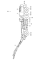
図1及び図2は本発明に係る低騒音型切削装置の一実施例として示す路面切削機10であり、図1はその路面切削機全体の外観を示す側面図、図2はその路面切削機全体を後方から見た斜視図である。以下の説明において、図1の左右方向左側を路面切削機10の前後方向前側、右側を後側とし、また上下方向を上下、紙面に垂直な方向を左右として説明する。
Figures 1 and 2 show a
図1及び図2に示す路面切削機10は、図示しないエンジンを搭載している路面切削機本体11を有している。路面切削機10の路面切削機本体11には、左右の前後位置にそれぞれ走行輪12(前輪12A、後輪12B、後輪12C)を有し、エンジンの駆動力で走行輪12を回転させて自走する。
The
また、路面切削機本体11には、前輪12Aと後輪12Bの間に、内部に切削ドラム室13を設けた切削ドラムボックス14が取り付けられている。切削ドラム室13内には、舗装路面の表面部位を切削する、外周面に切削ビットを設けた比較的左右方向(車幅方向)に長尺の切削ドラム15(図1参照)が配置されている。更に、切削ドラムボックス14の下面には、舗装路面の表面部位上に接地可能な接地ローラ16が取り付けられている。切削ドラムボックス14は、切削作業を行わないとき、舗装路面の表面部位から接地ローラ16が大きく離れる位置(図1中の位置)まで上昇し、切削ドラム15と共に退避している。すなわち、切削ドラムボックス14及び、切削ドラムボックス14の切削ドラム室13内に収容されている切削ドラム15は、路面切削機本体11に対して上下に昇降、左右にスライド可能に取り付けられている。
In addition, a
一方、路面切削機本体11は、切削作業が行われるとき、接地ローラ16が舗装路面の表面部位上に当接するまで下降されると共に、切削ドラム15も舗装路面の表面部位上に当接するまで下降される。そして、路面切削機本体11の自走を実現しているエンジンの駆動力により、切削ドラム15が回転され、その回転により切削ドラム15が、外周面に設けている切削ビットで舗装路面の表面部位を切削する。
Meanwhile, when cutting work is being performed, the road
また、切削ドラム15で切削された切削材は、路面切削機本体11上に設けられた図示しない第1のベルトコンベア上に送り出されて、第1のベルトコンベアで路面切削機本体11の前部に送られると共に、更に路面切削機本体11の前部に設けられている第2のベルトコンベアを有するコンベア装置17を介して、図示しない運搬車両(トラック)等上に搬出される。なお、切削ドラム15による切削作業が終わると、切削ドラム15及び切削ドラムボックス14は、図1に示す上昇位置まで再び戻される。
The cutting material cut by the
ところで、この種の路面切削機10では、エンジン部分における騒音と共に、切削ドラム15を高速で回転させて舗装路面の表面部位を切削するときに発生する切削音が問題になっている。そこで、路面切削機10においては、切削ドラム15が舗装路面の表面部位を切削するときに発生する切削音が周囲に放出されるのを低減する構造として、図1及び図2に示すように、切削ドラム室13の外側において、切削ドラム室13の側面外周及び上面外周の略全面を覆って、騒音抑制材30を取り付けている。
However, in this type of
騒音抑制材30は、切削ドラム室13の外側において、切削ドラム室13の側面外周及び上面外周の略全面を外側から略隙間無く覆ってカバーする状態にして取り付けているものであり、図3にその一例を模式的に示す。
The
図3に示す騒音抑制材30は、吸音性及び遮音性を有した柔軟性のあるカバーである。騒音抑制材30は、内側に吸音性を有する例えば25ミリ厚程度のニードルガラスクロスマットと遮音性を有する例えば2ミリ程度のブチル系シートを内蔵させ、外側を例えばシリコングラスクロスなどの表皮材で覆って一体化したカバーである。騒音抑制材30は複数枚に分割されており、切削ドラムボックス14の左右両側面を覆って取り付ける第1の騒音抑制材30Aと、切削ドラムボックス14の前後及び上面を覆って取り付ける第2の騒音抑制材30Bと、切削ドラムボックス14の下方部位に取り付けられた接地ローラ16の側面を覆って取り付けられる第3の騒音抑制材30Cと、を有している。
The
第1の騒音抑制材30Aと第2の騒音抑制材30Bと第3の騒音抑制材30Cには、互いに対応する位置に接合手段(例えば、面ファスナー等)を設けてある。そして、路面切削機本体11に騒音抑制材30を取り付ける場合は、騒音抑制材30に設けてある接合手段を用いて、第1の騒音抑制材30Aと第2の騒音抑制材30Bと第3の騒音抑制材30Cをそれぞれ所定の位置に、所定の順番で、所定の形状に組み合わせると、切削ドラム室13の側面及び上面の外周略全面が騒音抑制材30で覆われた状態となって取り付けられる。なお、本実施例においては、騒音抑制材30を、第1の騒音抑制材30Aと第2の騒音抑制材30Bと第3の騒音抑制材30Cの、3つに分割した構造を開示したが、騒音抑制材30は1つに一体化された構造であってもよいし、3つ以外に分割された構造であってもよい。
The first
したがって、騒音抑制材30で、切削ドラム室13の側面外周及び上面外周の略全面をそれぞれ外側から略隙間無く覆ってカバーしている路面切削機10の構造では、切削ドラム15で舗装路面の表面部位を切削するときに発生する、切削ドラムのビットが舗装路面の表面部位に当たった時の衝撃音(打撃音)、舗装路面の表面部位を掻き取る時に発生する引っ掻き音、切削材が切削ドラム室13の内壁面に衝突する時に発生する衝撃音(打撃音)などの切削騒音は、切削ドラム室13を外側から覆っている騒音抑制材30の吸音材及び遮音材により吸収及び遮音されて低減され、外部に放出される騒音を低減することができる。これにより、低騒音型の切削装置の実現が可能となる。
Therefore, in the structure of the
なお、本発明は、本発明の精神を逸脱しない限り種々の改変を成すことができ、そして、本発明が該改変されたものに及ぶことは当然である。 The present invention can be modified in various ways without departing from the spirit of the invention, and it goes without saying that the present invention extends to such modifications.
10 :路面切削機(低騒音型切削装置)
11 :路面切削機本体
12 :走行輪
13 :切削ドラム室
14 :切削ドラムボックス
15 :切削ドラム
17 :コンベア装置
18 :エンジンルーム
19 :エンジンフード
20 :吸気口
21 :排気口
30 :騒音抑制材
30A :第1の騒音抑制材
30B :第2の騒音抑制材
30C :第3の騒音抑制材
10: Road cutting machine (low noise cutting device)
11: Road milling machine body 12: Running wheel 13: Milling drum chamber 14: Milling drum box 15: Milling drum 17: Conveyor device 18: Engine room 19: Engine hood 20: Air intake 21: Exhaust port 30:
Claims (2)
前記切削ドラムを昇降可能に収容している切削ドラム室を有する切削装置本体と、
前記切削ドラム室の側面及び上面を各々覆って取り付けた吸音性と遮音性を有する騒音抑制材と、を備えた、
ことを特徴とする低騒音型切削装置。 A low-noise cutting device that cuts a surface portion of a paved road surface by lowering a cutting drum that can be raised and lowered until it contacts the surface portion of the paved road surface and moving the cutting drum with rotation,
A cutting device body having a cutting drum chamber in which the cutting drum is housed so as to be liftable and lowerable;
and a noise suppression material having sound absorbing and sound insulating properties, which is attached to cover each of the side and top surfaces of the cutting drum chamber.
A low noise cutting device characterized by:
ことを特徴とする請求項1に記載の低騒音型切削装置。 The noise suppression material is a flexible cover formed by covering the outside of a sound absorbing material and a sound insulating material with a skin material and integrating them, and is divided into a plurality of pieces, and is configured so that they can be assembled into a predetermined shape by connecting the pieces together at joint means provided at corresponding positions.
2. A low noise cutting device according to claim 1.
Priority Applications (1)
| Application Number | Priority Date | Filing Date | Title |
|---|---|---|---|
| JP2023142159A JP2025035239A (en) | 2023-09-01 | 2023-09-01 | Low noise cutting equipment |
Applications Claiming Priority (1)
| Application Number | Priority Date | Filing Date | Title |
|---|---|---|---|
| JP2023142159A JP2025035239A (en) | 2023-09-01 | 2023-09-01 | Low noise cutting equipment |
Publications (1)
| Publication Number | Publication Date |
|---|---|
| JP2025035239A true JP2025035239A (en) | 2025-03-13 |
Family
ID=94927695
Family Applications (1)
| Application Number | Title | Priority Date | Filing Date |
|---|---|---|---|
| JP2023142159A Pending JP2025035239A (en) | 2023-09-01 | 2023-09-01 | Low noise cutting equipment |
Country Status (1)
| Country | Link |
|---|---|
| JP (1) | JP2025035239A (en) |
-
2023
- 2023-09-01 JP JP2023142159A patent/JP2025035239A/en active Pending
Similar Documents
| Publication | Publication Date | Title |
|---|---|---|
| US4013302A (en) | Acoustically absorbent truck tire splash guard | |
| ATE360728T1 (en) | CAB FOR AN EXCAVATOR | |
| CN108513553A (en) | Working truck | |
| JP2025035239A (en) | Low noise cutting equipment | |
| CN101484645A (en) | Construction machine | |
| JPH11200412A (en) | Construction machine | |
| JP2012207490A (en) | Construction machine | |
| JP2025035238A (en) | Low noise road milling machine | |
| JP5603838B2 (en) | Combine | |
| KR101192386B1 (en) | Pavement cutting tool for nature-friendly low noise and the device | |
| JP6198668B2 (en) | Compaction vehicle | |
| JP4546911B2 (en) | Rear discharge type mowing device | |
| JP2014070427A (en) | Concrete cutter | |
| CN108162655B (en) | An outdoor rainproof numerical control engraving device | |
| JP4151492B2 (en) | Soundproof device for chassis dynamometer | |
| JP3112577U (en) | Soundproofing device for processing machine | |
| JP2002112613A (en) | Mower | |
| JP3668049B2 (en) | Road roller | |
| CN209869978U (en) | Low noise tire structure | |
| JP2003293600A (en) | Concrete ditch excavator | |
| JP3425863B2 (en) | Injection joint removal device | |
| KR102838041B1 (en) | Grinding dust cover for schmidt hammer impact surface for safety diagnosis | |
| JP7546978B1 (en) | Chipping device, chipping method, and cover used therein | |
| JPH0732902Y2 (en) | Soundproof engine work machine | |
| CN220787507U (en) | Material roll-up structure is used in callus on sole production |