JP2024039683A - gaming machine - Google Patents
gaming machine Download PDFInfo
- Publication number
- JP2024039683A JP2024039683A JP2022142568A JP2022142568A JP2024039683A JP 2024039683 A JP2024039683 A JP 2024039683A JP 2022142568 A JP2022142568 A JP 2022142568A JP 2022142568 A JP2022142568 A JP 2022142568A JP 2024039683 A JP2024039683 A JP 2024039683A
- Authority
- JP
- Japan
- Prior art keywords
- jackpot
- special
- game
- performance
- symbol
- Prior art date
- Legal status (The legal status is an assumption and is not a legal conclusion. Google has not performed a legal analysis and makes no representation as to the accuracy of the status listed.)
- Pending
Links
- 238000001514 detection method Methods 0.000 claims abstract description 292
- 238000012545 processing Methods 0.000 claims description 202
- 238000000034 method Methods 0.000 abstract description 341
- 230000008569 process Effects 0.000 abstract description 331
- 238000010304 firing Methods 0.000 abstract description 204
- 238000010586 diagram Methods 0.000 abstract description 20
- 230000000694 effects Effects 0.000 description 509
- 238000004519 manufacturing process Methods 0.000 description 172
- 238000003860 storage Methods 0.000 description 93
- 230000008859 change Effects 0.000 description 76
- 230000006870 function Effects 0.000 description 73
- 230000009467 reduction Effects 0.000 description 39
- 239000000872 buffer Substances 0.000 description 35
- 230000015654 memory Effects 0.000 description 24
- 238000012544 monitoring process Methods 0.000 description 22
- 238000013461 design Methods 0.000 description 19
- 101100452593 Caenorhabditis elegans ina-1 gene Proteins 0.000 description 18
- 238000005034 decoration Methods 0.000 description 18
- 238000012423 maintenance Methods 0.000 description 15
- 239000011295 pitch Substances 0.000 description 14
- 238000012790 confirmation Methods 0.000 description 12
- 230000005284 excitation Effects 0.000 description 12
- 230000036961 partial effect Effects 0.000 description 12
- 230000002829 reductive effect Effects 0.000 description 11
- 230000001276 controlling effect Effects 0.000 description 10
- 230000007423 decrease Effects 0.000 description 10
- 238000001994 activation Methods 0.000 description 9
- 238000004904 shortening Methods 0.000 description 9
- 238000011161 development Methods 0.000 description 8
- 238000005286 illumination Methods 0.000 description 8
- 230000000007 visual effect Effects 0.000 description 8
- 238000004458 analytical method Methods 0.000 description 7
- 230000001795 light effect Effects 0.000 description 7
- 230000003213 activating effect Effects 0.000 description 6
- 230000009471 action Effects 0.000 description 5
- 230000004913 activation Effects 0.000 description 5
- 230000005540 biological transmission Effects 0.000 description 5
- 230000005389 magnetism Effects 0.000 description 5
- 239000011347 resin Substances 0.000 description 5
- 229920005989 resin Polymers 0.000 description 5
- 230000004044 response Effects 0.000 description 5
- 101150110971 CIN7 gene Proteins 0.000 description 4
- 101100400452 Caenorhabditis elegans map-2 gene Proteins 0.000 description 4
- 101150110298 INV1 gene Proteins 0.000 description 4
- 101150064138 MAP1 gene Proteins 0.000 description 4
- 101100397044 Xenopus laevis invs-a gene Proteins 0.000 description 4
- 230000008901 benefit Effects 0.000 description 4
- 239000003990 capacitor Substances 0.000 description 4
- 238000004891 communication Methods 0.000 description 4
- 238000009826 distribution Methods 0.000 description 4
- 238000003825 pressing Methods 0.000 description 4
- 230000002441 reversible effect Effects 0.000 description 4
- 230000007704 transition Effects 0.000 description 4
- 230000001960 triggered effect Effects 0.000 description 4
- VYPSYNLAJGMNEJ-UHFFFAOYSA-N Silicium dioxide Chemical compound O=[Si]=O VYPSYNLAJGMNEJ-UHFFFAOYSA-N 0.000 description 3
- 230000005856 abnormality Effects 0.000 description 3
- 239000003086 colorant Substances 0.000 description 3
- 230000003247 decreasing effect Effects 0.000 description 3
- 239000004973 liquid crystal related substance Substances 0.000 description 3
- 230000007246 mechanism Effects 0.000 description 3
- 230000002265 prevention Effects 0.000 description 3
- 238000005096 rolling process Methods 0.000 description 3
- 241000167854 Bourreria succulenta Species 0.000 description 2
- 238000003491 array Methods 0.000 description 2
- 238000006243 chemical reaction Methods 0.000 description 2
- 235000019693 cherries Nutrition 0.000 description 2
- 230000009849 deactivation Effects 0.000 description 2
- 230000006872 improvement Effects 0.000 description 2
- 230000008054 signal transmission Effects 0.000 description 2
- 239000000725 suspension Substances 0.000 description 2
- 230000002195 synergetic effect Effects 0.000 description 2
- 210000003813 thumb Anatomy 0.000 description 2
- 101100286980 Daucus carota INV2 gene Proteins 0.000 description 1
- 241000220317 Rosa Species 0.000 description 1
- 241000219094 Vitaceae Species 0.000 description 1
- 101100397045 Xenopus laevis invs-b gene Proteins 0.000 description 1
- 230000003466 anti-cipated effect Effects 0.000 description 1
- 238000013459 approach Methods 0.000 description 1
- 230000001174 ascending effect Effects 0.000 description 1
- 238000007599 discharging Methods 0.000 description 1
- 230000005669 field effect Effects 0.000 description 1
- 239000005338 frosted glass Substances 0.000 description 1
- 235000021021 grapes Nutrition 0.000 description 1
- 210000004247 hand Anatomy 0.000 description 1
- 230000001788 irregular Effects 0.000 description 1
- 239000002991 molded plastic Substances 0.000 description 1
- 238000000465 moulding Methods 0.000 description 1
- 230000007935 neutral effect Effects 0.000 description 1
- 230000001105 regulatory effect Effects 0.000 description 1
- 230000000717 retained effect Effects 0.000 description 1
- 239000004065 semiconductor Substances 0.000 description 1
- 230000035939 shock Effects 0.000 description 1
- 238000009987 spinning Methods 0.000 description 1
- 230000001360 synchronised effect Effects 0.000 description 1
- 230000008685 targeting Effects 0.000 description 1
Images


Abstract
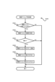
【課題】既存の信号と異なる所定の信号を外部装置に出力する場合の対応が簡易な遊技機を提供すること。【解決手段】払出制御用マイコン116の制御処理に基づく賞球払出信号は、払出制御基板110から出力されて外部端子板130に入力され、発射停止スイッチ115tの検知に基づく発射停止検知信号は、払出制御基板110を介して外部端子板130に入力される。外部端子板130に入力される信号は必ず払出制御基板110を経由することとなるので、外部装置500に対する外部信号の出力契機となる信号の出どころにかかわらず、払出制御基板110と外部端子板130との接続により外部信号(賞球情報信号、発射停止信号)を外部装置500に出力可能となる。これにより、既存の信号と異なる信号として発射停止信号を外部装置500に出力する構成を採る場合に簡易に対応可能である。【選択図】図55An object of the present invention is to provide a gaming machine that can easily handle cases where a predetermined signal different from existing signals is output to an external device. A prize ball payout signal based on the control process of a payout control microcomputer 116 is output from a payout control board 110 and input to an external terminal board 130, and a shooting stop detection signal based on detection of a shooting stop switch 115t is It is input to the external terminal board 130 via the payout control board 110. Since the signal input to the external terminal board 130 always passes through the payout control board 110, regardless of the source of the signal that triggers the output of the external signal to the external device 500, the signal input to the external terminal board 110 and the external terminal board 130 By connecting with the external device 500, external signals (prize ball information signal, firing stop signal) can be outputted to the external device 500. This makes it possible to easily accommodate a configuration in which the firing stop signal is output to the external device 500 as a signal different from existing signals. [Selection diagram] Figure 55
Description
本発明は、パチンコ遊技機(弾球遊技機)やスロットマシン(回胴式遊技機)等の遊技機に関する。 The present invention relates to gaming machines such as pachinko gaming machines (pinball gaming machines) and slot machines (spinning drum gaming machines).
従来、遊技球や遊技メダル等の遊技媒体を用いて遊技を行う遊技機が知られている。この種の遊技機には、遊技機が設置されるホール(遊技場)に設けられた外部装置(例えばホールコンピュータ)と接続される外部端子板が設けられており、外部端子板に入力した信号に基づいて、遊技状態等に関する種々の信号(情報)が外部装置に対して出力されるようになっている(例えば特許文献1を参照)。 Conventionally, gaming machines that play games using gaming media such as gaming balls and gaming medals have been known. This type of gaming machine is equipped with an external terminal board that is connected to an external device (for example, a hall computer) installed in the hall where the gaming machine is installed, and the signal input to the external terminal board is Based on this, various signals (information) regarding the gaming status and the like are output to an external device (see, for example, Patent Document 1).
遊技機には、いわゆる1種タイプや2種タイプ、1種2種混合タイプ、一般電役タイプ等の仕様がある。また、いわゆる1種タイプの遊技機には、停止表示された大当り図柄の種類に基づいて確変遊技状態に移行するか否かが決まる図柄確変機や、アタッカー内の特定領域への遊技球の通過有無に基づいて確変遊技状態に移行するか否かが決まるV確機等の仕様がある。このように遊技機の仕様は多種多様であり、遊技機の仕様によっては、既存の信号と異なる所定の信号を外部装置に出力することが考えられる。この場合、遊技機の開発や製造過程において極力簡易に対応できるようにすることが望ましい。
Gaming machines have specifications such as so-called 1 type, 2 type, 1 type and 2 mixed type, and general electric role type. In addition, the so-called
本発明は上記事情に鑑みてなされたものであり、その目的とするところは、既存の信号と異なる所定の信号を外部装置に出力する場合の対応が簡易な遊技機を提供することにある。 The present invention has been made in view of the above circumstances, and its purpose is to provide a gaming machine that can easily handle the case where a predetermined signal different from the existing signal is output to an external device.
前述の課題を解決するために、本発明は以下の手段を採用した。 In order to solve the above problems, the present invention employs the following means.
手段1の遊技機は、
遊技の結果に影響を及ぼす制御処理を実行可能な制御部が設けられた主基板と、
遊技機の外部に設けられた外部装置に所定の外部信号を出力可能な外部端子板と、を備え、
前記外部端子板に入力した信号に基づく外部信号が前記外部端子板から前記外部装置に出力されるように構成された遊技機であって、
所定の事象を検知可能な検知手段を備え、
前記制御部による制御処理に基づく信号と、前記検知手段による検知に基づく信号とが、前記外部端子板に入力可能とされている
ことを要旨とする。
The gaming machine of
a main board provided with a control unit capable of executing control processing that affects the result of the game;
An external terminal board capable of outputting a predetermined external signal to an external device provided outside the gaming machine,
A gaming machine configured such that an external signal based on a signal input to the external terminal board is output from the external terminal board to the external device,
Equipped with a detection means capable of detecting a predetermined event,
The gist is that a signal based on control processing by the control unit and a signal based on detection by the detection means can be input to the external terminal board.
なお、所定の事象とは、例えば、遊技機を使用(遊技)したり管理したりする者(遊技者、遊技ホール店員など)による人為的な操作や行為等に起因して発生する事象や、遊技機が備える部材、装置等の作動に起因して発生する事象、遊技の過程や結果として発生する事象など、遊技機の構成(構造)や稼働に関連して発生する事象であって、発生の有無(発生したか否か)が認識(検知)可能とされる事象である。 Note that the predetermined event is, for example, an event that occurs due to an artificial operation or action by a person who uses (plays) or manages a gaming machine (player, gaming hall clerk, etc.); Events that occur related to the configuration (structure) and operation of the gaming machine, such as events that occur due to the operation of the parts and devices included in the gaming machine, and events that occur as a result of the game process. It is an event whose presence or absence (occurrence or not) can be recognized (detected).
以上の本発明によれば、既存の信号と異なる所定の信号を外部装置に出力する場合の対応が簡易な遊技機を提供することが可能である。 According to the present invention described above, it is possible to provide a gaming machine that can easily handle the case where a predetermined signal different from an existing signal is output to an external device.
次に、本発明の実施の形態について実施例を用いて説明する。以下では、遊技に用いる遊技媒体が遊技球とされ、遊技盤面に向けて遊技球を発射することで遊技を進行させることが可能なパチンコ遊技機(弾球遊技機)に本発明を適用した例を説明する。 Next, embodiments of the present invention will be described using examples. In the following, an example in which the present invention is applied to a pachinko game machine (pinball game machine) in which the game medium used for the game is a game ball, and the game can be advanced by firing the game ball toward the game board surface. Explain.
なお、以下の説明において、単に前側(前方)とは、遊技機を正面視した場合の表面側(手前側)であって、遊技時に遊技者が位置する側のことである。また、単に後側(後方)とは、遊技機を正面視した場合の裏面側(背面側)のことである。さらに、単に上側(上方)、下側(下方)、左側(左方)、右側(右方)とは、遊技機を正面視した場合の上・下・左・右の各方向のことであり、例えば、図1や図3における上側、下側、左側、右側を指す。 In the following description, the front side (front side) simply refers to the front side (front side) when the gaming machine is viewed from the front, and the side on which the player is positioned during gaming. In addition, simply the rear side (rear side) refers to the back side (back side) when the gaming machine is viewed from the front. Furthermore, simply the upper side (upper side), lower side (lower side), left side (left side), and right side (right side) refer to the upper, lower, left, and right directions when looking at the gaming machine from the front. , for example, refers to the upper side, lower side, left side, and right side in FIGS. 1 and 3.
本実施例のパチンコ遊技機1は、始動口への遊技球の入球に基づいて特別図柄が変動表示する図柄変動遊技(単に「変動遊技」ともいう。)を行い、変動遊技の結果として大当り図柄が表示(停止表示)されると、遊技者に所定の遊技価値(例えば賞球)を付与する大当り遊技(特別遊技)が実行可能となる所謂「デジパチタイプ」のパチンコ遊技機である。
The
[パチンコ遊技機1の基本構成]
図1~図3に示すように、パチンコ遊技機1は、遊技機枠50と、遊技機枠50内に取り付けられた遊技盤2とを備えている。遊技盤2は遊技機枠50に対して着脱自在に構成されている。図3は、遊技盤2を遊技機枠50から取り外した状態を示す。
[Basic configuration of pachinko machine 1]
As shown in FIGS. 1 to 3, the
遊技機枠50は、装飾面を有する前面枠51と、遊技盤2等が取り付けられる本体枠52と、パチンコ遊技機1を遊技ホールの島設備に取り付けるための外枠53と、を有して構成されている。前面枠51、本体枠52及び外枠53は、それぞれ、パチンコ遊技機1の一側端側(本実施例では左端側)で軸支されて開閉可能に構成されている。すなわち、外枠53に対して本体枠52が開閉可能に軸支され、本体枠52に対して前面枠51が開閉可能に軸支されている。
The
前面枠51には、回動操作部60aの操作量に応じた発射強度で遊技球を発射させるための発射ハンドル60、遊技球を貯留可能であり貯留した遊技球を発射装置側に供給可能な打球供給皿(上皿)61、及び打球供給皿61に収容しきれない遊技球を貯留可能な余剰球受皿(下皿)62が設けられている。
The
前面枠51には、遊技の進行に伴って実行される遊技演出の実行中などに遊技者が操作可能な第1演出ボタン63a、第2演出ボタン63b(これら2個の演出ボタンを総称して単に「演出ボタン63」ともいう。)や、遊技の状況に応じて様々な光を発することが可能な装飾用の枠ランプ66、遊技の状況に応じて様々な音(効果音)を発することが可能なスピーカ67等も設けられている。
The
演出ボタン63は、遊技者が入力を行う際に用いる入力手段として機能するものであり、遊技者が操作可能な操作手段としても機能するものである。遊技者等は、遊技の状況や実行される遊技演出の種類等に応じて、使用(操作)する演出ボタン(第1演出ボタン63a又は第2演出ボタン63b)を使い分けることができる。例えば、遊技演出の実行中に第1演出ボタン63a又は第2演出ボタン63bを操作すると、当該操作に基づいて所定の操作対応演出が行われる。本実施例では、前面枠51のうち上皿61の上面(天面)に第1演出ボタン63aが設けられており、下皿62の左側前面に第2演出ボタン63bが設けられている。
The production button 63 functions as an input means used when the player makes an input, and also functions as an operation means that can be operated by the player. A player or the like can selectively use (operate) a performance button (
第1演出ボタン63aは、所定の作動態様で作動可能な可動式の操作手段として構成されている。本実施例では、その作動態様を振動としている。第1演出ボタン63aの振動は、例えば、第1演出ボタン63aを、偏心モータ(振動モータ)を含む演出ボタンユニット(演出ボタン装置)として構成し、偏心モータを駆動させることにより実現することができる。このように作動(振動)可能に構成される第1演出ボタン63aは、パチンコ遊技機1の前面側(前面構成部材)に作動可能に設けられた演出用の可動部(「演出可動部」ともいう。)として機能する。
The
なお、第1演出ボタン63aの作動態様は振動に限られず、例えば、上方への突出や回転等としてもよく、振動、突出、回転等の複数種の作動態様の中から演出パターンに基づいて選択された作動態様で作動可能となるようにしてもよい。また、第2演出ボタン63bも所定の作動態様で作動可能に構成してもよい。
The operating mode of the
また、演出ボタン63の構成は本実施例の態様に限らず、遊技者が入力を行うことができるものであれば足り、例えば、レバータイプの入力手段(操作手段)であってもよいし、遊技者が直接ボタン部に接触して入力を行う接触式の入力手段(例えば、出没式、タッチセンサ式等)であってもよいし、遊技者の身体の一部が近接したことを検知して入力を行う非接触式の入力手段(光電式等)であってもよい。 Further, the configuration of the production button 63 is not limited to the aspect of this embodiment, and may be any configuration that allows the player to input, for example, it may be a lever type input means (operation means), It may be a contact-type input means (for example, a retractable type, a touch sensor type, etc.) in which the player inputs by directly touching the button part, or it may be a contact-type input means (for example, a retractable type, a touch sensor type, etc.), or a type of input means that detects when a part of the player's body approaches. A non-contact type input means (photoelectric type, etc.) that performs input may also be used.
遊技盤2には、発射ハンドル60(回動操作部60a)の操作により発射された遊技球が流下する遊技領域3が、レール部材4で囲まれて形成されている。遊技盤2(遊技領域3)は、前面枠51に設けられる窓部(視認窓)を介してパチンコ遊技機1の手前側(遊技者側)から視認可能とされる(図1を参照)。
On the
遊技領域3には、遊技球を誘導する複数の遊技釘16が突設されており、レール部材4の先端には球戻り防止片6が設けられている。球戻り防止片6は、一旦遊技領域へ誘導された遊技球を発射装置側へ戻るのを防止するためのものである。また、遊技盤2には、遊技の状況に応じて様々な光を発することが可能な装飾用の盤面ランプ5(図5を参照)も設けられている。
A plurality of game nails 16 for guiding game balls are protruded in the
遊技盤2の中央付近(遊技領域内)には画像表示装置7(演出表示装置、図柄表示装置)が設けられている。画像表示装置7は液晶表示器(液晶ディスプレイ)を備えてなるもので、その表示画面7aが遊技盤2(遊技領域3)の略中央に設けられた開口を介して前方から視認可能となるように、遊技盤2の裏面側に設けられる。
An image display device 7 (effect display device, symbol display device) is provided near the center of the game board 2 (inside the game area). The
画像表示装置7の表示画面7aには、演出図柄8が表示される演出図柄表示領域7b(「演出図柄表示部」ともいう。)が設けられている。演出図柄8は、左演出図柄8L、中演出図柄8C及び右演出図柄8Rの3つの図柄により構成され、後述の特別図柄の変動表示に同期して変動表示を行い、特別図柄の停止表示に同期して停止表示を行う。変動表示の態様としては、例えば上下、左右、斜め方向等にスクロール表示する態様がある。演出図柄8L,8C,8Rの何れか又は全部を指して単に「演出図柄8」ともいう。
A
演出図柄表示領域7bは、「左」「中」「右」の3つの図柄表示エリアからなり、左の図柄表示エリアには左演出図柄8Lが表示され、中の図柄表示エリアには中演出図柄8Cが表示され、右の図柄表示エリアには右演出図柄8Rが表示される。なお、左・中・右の図柄表示エリアの位置は夫々区別して設ける必要はなく、左・中・右の演出図柄の表示エリアをそれぞれ図柄表示エリア(演出図柄表示領域7b)の全体としてもよい。
The effect
本実施例の演出図柄8L,8C,8Rは、それぞれ「1」~「9」までの数字図柄(識別情報種、図柄種)からなるもので、これらの数字図柄が順に表示されるものとなっている。具体的に、当該演出図柄8の変動表示は、「1」→「2」・・・「8」→「9」の順(昇順)で演出図柄をスクロール表示させることによって行われるものとなっており、「9」まで到達したら「1」に戻って、スクロール表示を変動終了(停止表示)まで繰り返すものとなっている。
The
本実施例では、演出図柄8を構成する「1」~「9」の図柄のそれぞれに色の情報を含ませており、各図柄を色によって分類できるものとしている。具体的には、奇数図柄である「3」と「7」を赤色の図柄(以下「赤図柄」ともいう。)としており、これ以外の奇数図柄である「1」、「5」、「9」を緑色の図柄(以下「緑図柄」ともいう。)としている。また、偶数図柄である「2」、「4」、「6」、「8」を青色の図柄(以下「青図柄」ともいう。)としている。
In this embodiment, each of the symbols "1" to "9" that make up the
演出図柄表示領域7bに表示(停止表示)される左、中、右の演出図柄の組み合わせ(停止表示態様)によって、後述の第1特別図柄表示器41a(「第1特別図柄表示部」ともいう。)に表示される第1特別図柄の変動表示の結果や、第2特別図柄表示器41b(「第2特別図柄表示部」ともいう。)に表示される第2特別図柄の変動表示の結果、つまり、特別図柄当否判定(単に「当否判定」ともいう。)の結果を、遊技者が認識し易いように表示する。本実施例では、変動表示している3つの演出図柄8L,8C,8Rが停止表示する順序(停止順)を、原則、「左→右→中」としている。すなわち、停止順が1番目の停止図柄を左演出図柄8Lとし、停止順が2番目の停止図柄を右演出図柄8Rとし、停止順が3番目(最後)の停止図柄を中演出図柄8Cとしている。なお、停止順が1番目の停止図柄のことを「第1停止図柄」ともいい、停止順が2番目の停止図柄のことを「第2停止図柄」ともいい、停止順が3番目の停止図柄のことを「第3停止図柄」や「最終停止図柄」ともいう。
Depending on the combination (stop display mode) of the left, middle, and right performance symbols displayed (stop display) in the performance
ここで、特別図柄及び演出図柄の何れか一方又は両方を指して単に「図柄」又は「識別情報」ともいい、普通図柄のことを「普図」又は「普通識別情報」ともいい、特別図柄のことを「特図」、「特別識別情報」又は「第1識別情報」ともいい、第1特別図柄のことを「特図1」、「第1特図」又は「第1特別識別情報」ともいい、第2特別図柄のことを「特図2」、「第2特図」又は「第2特別識別情報」ともいい、演出図柄のことを「演出識別情報」又は「第2識別情報」ともいう。
Here, either or both of the special design and production design are simply referred to as "design" or "identification information", and the normal design is also referred to as "common design" or "normal identification information", and the special design This is also called a "special pattern", "special identification information" or "first identification information", and the first special pattern is also called "
また、第1特別図柄を表示する後述の第1特別図柄表示器41a、第2特別図柄を表示する後述の第2特別図柄表示器41b及び特別図柄の表示に係る制御を行う後述の主制御部80(遊技制御用マイコン81)の少なくとも一つを指して「特別識別情報表示手段」又は「第1識別情報表示手段」ともいい、演出図柄8を表示する画像表示装置7(表示画面7a)、演出図柄8の表示に係る制御を行う後述のサブ制御部90(演出制御用マイコン91)及び画像制御部100(画像制御用マイコン101)の少なくとも一つを指して「演出識別情報表示手段」又は「第2識別情報表示手段」ともいう。さらに、画像表示装置7、第1特別図柄表示器41a及び第2特別図柄表示器41bのことを「識別情報表示手段」又は「図柄表示手段」ともいい、単に「表示手段」ともいう。
In addition, a first
演出図柄8の停止表示態様は次のように定めることができる。例えば、特別図柄当否判定の結果が大当りの場合、「222」や「777」などの三桁同一の図柄配列(所謂「ゾロ目」)で演出図柄8を停止表示することができ、特別図柄当否判定の結果が外れの場合、「637」や「373」などの3つの図柄のうち少なくとも1つの図柄が他の図柄と異なる図柄配列(所謂「バラケ目」)で演出図柄8を停止表示することができる。三桁同一の図柄配列(ゾロ目)のことを「当り図柄配列」ともいい、少なくとも1つの図柄が他の図柄と異なる図柄配列(バラケ目)のことを「外れ図柄配列」ともいう。当り図柄配列及び外れ図柄配列には、それぞれ複数種の図柄配列(停止表示態様)が存在する。また、特別図柄当否判定の結果が大当りの場合、その大当りの種類によってゾロ目又はゾロ目以外の停止表示態様で演出図柄8を停止表示することもできる。
The stop display mode of the
遊技者は、画像表示装置7の表示画面7aに表示される演出図柄8を見ることで、遊技の進行状況を容易に把握することが可能となる。つまり遊技者は、一般的には特別図柄当否判定の結果を第1特別図柄表示器41aや第2特別図柄表示器41bに表示される特別図柄を見て直接的に把握するのではなく、表示画面7a(演出図柄表示領域7b)に表示される演出図柄8を見て把握する。こうした演出図柄8を用いた遊技演出は、特別図柄当否判定の結果を遊技者に報知する演出(「報知演出」ともいう。)であるといえる。演出図柄8を用いた遊技演出(報知演出)のことを「演出図柄遊技演出」ともいい、演出図柄8を変動表示させて停止表示(確定表示)させる演出のことを「変動演出」ともいう。
By looking at the
ここで、特別図柄当否判定の結果のうち「大当り」のことを「特定結果」ともいい、「外れ」のことを「非特定結果」ともいう。また、特別図柄当否判定の結果が「大当り」の場合に対応する特別図柄の表示態様(停止表示態様)のことを「特定表示態様」又は「特定表示結果」ともいい、特別図柄当否判定の結果が「外れ」の場合に対応する特別図柄の表示態様(停止表示態様)のことを「非特定表示態様」又は「非特定表示結果」ともいい、特別図柄当否判定の結果が「大当り」の場合に対応する演出図柄8の表示態様(当り図柄配列)のことを「特別表示態様」又は「特別表示結果」ともいい、特別図柄当否判定の結果が「外れ」の場合に対応する演出図柄8の表示態様(外れ図柄配列)のことを「非特別表示態様」又は「非特別表示結果」ともいう。さらに、特別図柄当否判定の結果が大当りであることに基づいて実行される特別図柄及び/又は演出図柄の変動表示のことを「大当り変動」又は「特定変動」ともいい、特別図柄当否判定の結果が外れであることに基づいて実行される特別図柄及び/又は演出図柄の変動表示のことを「外れ変動」又は「非特定変動」ともいう。
Here, among the results of the special symbol validity determination, a "jackpot" is also referred to as a "specific result," and a "miss" is also referred to as a "non-specific result." In addition, the display mode (stop display mode) of the special symbol corresponding to the case where the result of the special symbol validity determination is a "jackpot" is also referred to as the "specific display format" or "specific display result", and the result of the special symbol validity determination. The display mode (stop display mode) of the special symbol that corresponds to the case where is a "miss" is also referred to as the "non-specific display mode" or "non-specific display result", and when the result of the special symbol validity judgment is a "jackpot" The display mode (winning pattern arrangement) of the
画像表示装置7の表示画面7a上では、前述のような演出図柄8を用いた遊技演出(演出図柄遊技演出、報知演出、変動演出)を表示するほか、大当り遊技に伴って実行される大当り遊技演出(特別遊技演出)や、客待ち用のデモ演出などの各種演出表示が表示される。演出図柄遊技演出や大当り遊技演出やデモ演出では、数字等の演出図柄のほか、背景画像やキャラクタ画像等、演出図柄以外の種々の画像(演出画像)も表示される。
On the
またデモ演出では、不図示の演出設定画面が表示可能となっている。演出設定画面は、例えば、効果音等の音量や、表示画面7aの明るさ、盤面ランプ5や枠ランプ66等の電飾部材の明るさ、背景表示、予告演出の実行条件等、当該遊技機の演出に関する設定を遊技者が行うための画面である。遊技者は、デモ演出が実行される客待ち中(待機中)に演出ボタンや他の操作手段(例えば操作レバーや十字キー等)を操作して表示画面7aに演出設定画面を表示させ、演出設定画面の内容にしたがって演出ボタン等を操作することで、演出に関する様々な設定を任意に行うこと(所謂「カスタマイズ」)が可能となる。
Furthermore, in the demonstration performance, a performance setting screen (not shown) can be displayed. The performance setting screen includes settings for the game machine, such as the volume of sound effects, the brightness of the
表示画面7aには、演出図柄8とは別に、特別図柄当否判定の結果を示す(報知する)判定図柄8sが表示される判定図柄表示領域7cが設けられている(図3を参照)。本実施例では、演出図柄表示領域7bの右上方(表示画面7aの右上部)に判定図柄表示領域7cが設けられている(図3を参照)。判定図柄表示領域7cの大きさは、演出図柄表示領域7bよりも小さく、これに伴って、判定図柄8sの大きさも演出図柄8よりも小さくなっている。判定図柄8sのことを「小図柄」又は「小識別情報」ともいう。
The
判定図柄8sは、演出図柄8と同様に、左判定図柄8sL、中判定図柄8sC及び右判定図柄8sRの3つの図柄により構成され、後述の特別図柄の変動表示に同期して変動表示を行い、特別図柄の停止表示に同期して停止表示を行う。判定図柄8sの変動表示の態様としては、例えば上下又は左右方向にスクロール表示する態様や、上下又は左右方向に回転表示する態様等がある。左判定図柄8sL、中判定図柄8sC及び右判定図柄8sRの何れか又は全部を指して単に「判定図柄8s」ともいう。
Similar to the
判定図柄表示領域7cにおいても、左、中、右の判定図柄8sの組み合わせ(停止表示態様)によって、特別図柄当否判定の結果が表示される。つまり、特別図柄当否判定の結果に基づいて判定図柄8sが変動表示されて停止表示される。本実施例では、演出図柄表示領域7bに表示される演出図柄8の停止表示態様(図柄配列、確定停止図柄)と同じ停止表示態様(図柄配列)で判定図柄8sが表示されるようになっている。但し、演出図柄8のような停止順は定められておらず、3つの判定図柄8sL,8sC,8sRは、特別図柄の変動表示の開始に伴って一斉に変動表示を開始し、特別図柄の停止表示に伴って一斉に停止表示するように構成されている。
Also in the determination
なお、演出図柄8と判定図柄8sとで停止表示態様を異ならせてもよい。また、特別図柄当否判定の結果が大当りの場合の停止表示態様(当り図柄配列)を演出図柄8と判定図柄8sとで同じとし、外れの場合の停止表示態様(外れ図柄配列)を演出図柄8と判定図柄8sとで異ならせてもよい。外れの場合の停止表示態様(外れ図柄配列)を演出図柄8と判定図柄8sとで異ならせる場合、判定図柄8sの外れ図柄配列は1種類のみ(例えば「246」等)とすることができる。遊技者は主に演出図柄8を見て当否判定の結果(当り外れ)を把握することから、判定図柄8sの外れ図柄配列を演出図柄8と同様に複数種類設ける必要性は低いからである。また、遊技進行過程で行われる特別図柄当否判定の結果(変動遊技の結果)は、大当り確率を鑑みると外れになることが殆どであり、判定図柄8sの外れ図柄配列を1種類とすることで、図柄表示制御の効率化や簡素化等を図ることが可能となる。
In addition, the stop display mode may be made different between the
判定図柄8sを表示する(判定図柄表示領域7cを設ける)のは、例えば、変動演出の実行中において、後述の予告演出やスーパーリーチ演出など遊技者の大当りに対する期待感を煽る演出画像が表示画面7aの略全体に表示される際、その演出画像により演出図柄8が隠されたり、演出図柄8が非表示となったり(消去されたり)する等、演出図柄8が視認できない状態になることがあるからである。つまり、演出図柄8が視認できない(表示されない)状態になったとしても、特別図柄が変動表示中であることや停止表示(確定停止)したことを、判定図柄8sを通じて把握することが可能となっている。このため、変動遊技が実行可能とされる遊技状態(「変動遊技状態」ともいう。)において判定図柄8は常に表示される。
The reason why the
なお、本実施例の判定図柄8sは、演出図柄8のように色による区別はなく、数字(図柄種)に関係なく同じ色で表示されるものとしている。本実施例では、判定図柄8sの色(表示色)を白と黒の中間色である「灰色(グレー)」の一色としている。判定図柄8sを比較的目立たない灰色(中間色)とするのは、判定図柄8sは、特別図柄当否判定の結果を把握するために遊技者が主として見る図柄(すなわち、特別図柄当否判定の結果を遊技者に報知する図柄)として機能するものではなく、主に特別図柄の変動状況を示す図柄として機能するものであり、演出図柄8のように目立たせる必要はないからである。また、判定図柄8sの色(表示色)を一色とすることで、図柄表示制御の効率化や簡素化等を図ることが可能となるからである。但し、判定図柄8sについても演出図柄8と同様に色の情報を含ませてもよく、演出図柄8と同様の色分けとしたり異なる色分けとしたりすることができる。
Note that the
また表示画面7aには、後述の第1特図保留の記憶数に応じて第1演出保留9aを表示する第1演出保留表示領域9c(第1演出保留表示部)と、後述の第2特図保留の記憶数に応じて第2演出保留9bを表示する第2演出保留表示領域9d(第2演出保留表示部)とが設けられている。本実施例では、演出図柄表示領域7bの下方(表示画面7aの下部)に第1演出保留表示領域9c及び第2演出保留表示領域9dが設けられている(図3を参照)。第1演出保留や第2演出保留の表示態様(表示数)により、後述の第1特図保留表示器43aにて表示される第1特図保留の記憶数や第2特図保留表示器43bにて表示される第2特図保留の記憶数を、遊技者にわかりやすく示すことができる。
In addition, the
ここで、第1演出保留表示領域9cに表示される第1演出保留9aのことを「第1保留アイコン」又は「第1記憶情報」ともいい、第2演出保留表示領域9dに表示される第2演出保留9bのことを「第2保留アイコン」又は「第2記憶情報」ともいい、第1演出保留9a及び第2演出保留9bの何れか一方又は両方を指して「保留アイコン」又は「記憶情報」ともいう。また。第1演出保留表示領域9cのことを「第1記憶情報表示部」又は「第1記憶情報表示手段」ともいい、第2演出保留表示領域9dのことを「第2記憶情報表示部」又は「第2記憶情報表示手段」ともいい、第1演出保留表示領域9c及び第2演出保留表示領域9dの何れか一方又は両方を指して「記憶情報表示部」又は「記憶情報表示手段」ともいう。
Here, the
また図3に示すように、表示画面7aには、現在変動表示している特別図柄(第1特別図柄又は第2特別図柄)に対応する演出保留、すなわち、消化された特図保留に対応する演出保留(第1演出保留9a又は第2演出保留9b)を表示する変動保留表示領域9eが設けられている(図3を参照)。本実施例では、第1演出保留表示領域9c及び第2演出保留表示領域9dの左側に変動保留表示領域9eが設けられている。
In addition, as shown in FIG. 3, the
第1演出保留表示領域9cに表示される第1演出保留9aは、当該表示領域9cの左端から右端に向かって順に特図1保留球数「1」、「2」、「3」、「4」に対応するものとなっており、第2演出保留表示領域9dに表示される第2演出保留9bは、当該表示領域9dの左端から右端に向かって順に特図2保留球数「1」、「2」、「3」、「4」に対応するものとなっている。このため、特図1保留球数「1」に対応する第1特別図柄の変動表示の開始(第1特図保留の消化)に伴って、当該保留に対応する第1演出保留9a(第1演出保留表示領域9cの左端に表示される第1演出保留9a)が第1演出保留表示領域9cから変動保留表示領域9eへ移動する(移動表示される)。また、特図2保留球数「1」に対応する第2特別図柄の変動表示の開始(第2特図保留の消化)に伴って、当該保留に対応する第2演出保留9b(第2演出保留表示領域9dの左端に表示される第2演出保留9b)が第2演出保留表示領域9dから変動保留表示領域9eへ移動する(移動表示される)。なお、特図保留球数が「0」の状態で始動口(第1始動口20又は第2始動口21)に遊技球が入球して特別図柄の変動表示が開始される場合、当該変動表示(変動遊技)の開始契機となる始動入球に伴って変動保留表示領域9eに演出保留(第1演出保留9a又は第2演出保留9b)が表示される。
The
ここで、変動保留表示領域9eも「記憶情報表示部」又は「記憶情報表示手段」ということができ、変動保留表示領域9eに表示される演出保留も「記憶情報」又は「保留アイコン」ということができる。また、変動保留表示領域9eに表示される演出保留のことを「変動記憶情報」、「変動保留アイコン」又は「アクティブ保留アイコン」ともいい、演出保留表示領域9c、9dに表示される演出保留(保留アイコン)及び変動保留表示領域9eに表示される演出保留(アクティブ保留アイコン)のことを総じて「記憶情報」又は「保留アイコン」ともいう。また、演出保留9a,9bを表示することが可能な演出保留表示領域9c,9d及び変動保留表示領域9eのことを「演出保留表示部」又は「演出保留表示手段」ともいう。
Here, the variable
以上のように、種々の演出表示や演出画像を表示可能な表示画面7a(画像表示装置7)のことを「演出表示部」又は「演出表示手段」ともいう。また、演出図柄8を用いた遊技演出(演出図柄遊技演出、報知演出、変動演出)や大当り遊技演出、デモ演出、後述の予告演出など、表示画面7aに表示されることにより行われる演出(表示画面上で行われる演出)のことを「表示演出」ともいう。
As described above, the
遊技盤2(遊技領域3)の中央付近であって画像表示装置7(表示手段)の前方には、表示画面7aを取り囲むようにしてセンター装飾体10(所謂「センター役物」)が設けられている。センター装飾体10は、プラスチック製(樹脂製)の成型物によって構成されるもので、中央が開口した枠状の部品(盤部品)として、遊技盤2の表面(前面)に取り付けられるものである。当該センター装飾体10の中央開口を介して画像表示装置7の表示画面7aが視認可能とされる。
Near the center of the game board 2 (game area 3) and in front of the image display device 7 (display means), a center decoration body 10 (so-called "center accessory") is provided so as to surround the
センター装飾体10の下部には、遊技球が転動可能な遊技球転動面を有するステージ部11が設けられており、センター装飾体10の左部には、中空状のワープ部12が設けられている。ワープ部12にはワープ入口とワープ出口とが設けられており、遊技領域3(左遊技領域3A)を流下する遊技球をワープ入口から受け入れてワープ出口から排出することで、当該遊技球をステージ部11へ誘導する。ステージ部11の転動面に誘導された遊技球は、ステージ部11に誘導されない遊技球よりも高い可能性で後述の第1始動口20に入球可能とされる。また、センター装飾体10の上部には、LED等の電飾部材(盤面ランプ5)を有し遊技状態に応じて点灯・点滅等が可能であって、文字や図形等を象った装飾部材13が設けられている。
A
センター装飾体10の中央開口左側には、後述する左可変演出部材14Lを前方(手前側)から覆うことが可能な左カバー部材17Lが設けられており、センター装飾体10の中央開口右側には、後述する右可変演出部材14Rを前方(手前側)から覆うことが可能な右カバー部材17Rが設けられている。左可変演出部材14L及び右可変演出部材14Rの何れか一方又は両方を指して「可変演出部材」(可変演出部材14)ともいい、左カバー部材17L及び右カバー部材17Rの何れか一方又は両方を指して「カバー部材」(カバー部材17)ともいう。
On the left side of the center opening of the
カバー部材17は、センター装飾体10に一体的に設けられるもので、不透明にするなど、カバー部材17を介してその後方(裏側)を視認することが困難(不可能)となるように構成されている。
The
遊技盤2と該遊技盤2の後方に配置される画像表示装置7(表示画面7a)との間には、可変演出部材14を含んで構成される後述の可変演出ユニット140(可変演出装置)が設けられている(図44を参照)。これにより、表示画面7aとカバー部材17との間(表示画面7aより手前側)に可変演出部材14が位置するものとなっている。
Between the
本実施例の可変演出部材14は、旗(フラッグ)をモチーフにした造形物により構成されるもので、旗部14a(旗部14aL,14aR)を含むものとされている。この可変演出部材14は、普段は図3に示すように、ステージ部11側(センター装飾体10の下部側)に設定される始点位置(「初期位置」又は「待機位置」ともいう。)に位置して、上下方向に真っすぐ立った状態(「起立状態」ともいう。)となっている。このように可変演出部材14が始点位置にあり且つ起立状態にあることを「非作動状態」又は「待機状態」ともいう。
The
可変演出部材14は、カバー部材17の後方(裏側)で始点位置と終点位置との間を上下方向に移動(上下動)することが可能となっており、その移動範囲内の所定位置で左右方向に回動することが可能となっている。すなわち、左可変演出部材14Lは、左カバー部材17Lの後方(裏側)で始点位置と終点位置との間を上下方向に移動することが可能であるとともに、その移動範囲内の所定位置で、起立状態と右側(表示画面7aの中央側)へ約90度倒れた状態(「傾倒状態」ともいう。)との間で回動することが可能である。また、右可変演出部材14Rは、右カバー部材17Rの後方(裏側)で始点位置と終点位置との間を上下方向に移動することが可能であるとともに、その移動範囲内の所定位置で、起立状態と左側(表示画面7aの中央側)へ約90度倒れた状態(傾倒状態)との間で回動することが可能である。
The
本実施例では、可変演出部材14が起立状態にあるとき、可変演出部材14の全体がカバー部材17の後方に隠れるようになっている。このため、カバー部材17と表示画面7aとの間(隙間)を覗き込まない限り、可変演出部材14を前方から視認することは困難(実質的に不可能)である。したがって、通常では、表示画面7aを見て遊技をしている遊技者に、起立状態にある可変演出部材14は見えないようになっている。そして、例えば、大当りの可能性が相対的に高い遊技演出の実行に伴って可変演出部材14が回動することで、カバー部材17に隠れていた可変演出部材14が現れて、可変演出部材14の旗部14aが前方から見えるようになる。これにより、遊技者は大当りへの期待感を高めることとなる。可変演出部材14(可変演出ユニット140)の詳細については後述する。
In this embodiment, when the
ここで、可変演出部材14は所謂「ギミック」に相当するものであり、可変演出部材14を作動させる演出は「ギミック演出」に相当するものである。可変演出部材14を作動させる演出(ギミック演出)のことを「可変演出」又は「可動演出」ともいい、可変演出部材14(ギミック)のことを「可変演出手段」又は「可動演出手段」ともいう。可変演出部材14以外にも、例えば、演出ボタン63が遊技演出に伴って振動等する場合、演出ボタン63を作動させる演出のことも「可変演出」又は「可動演出」ということができ、演出ボタン63のことも「可変演出手段」又は「可動演出手段」ということができる。
Here, the
また、遊技の状況に応じて様々な音(効果音)をスピーカ67から発生(出力)させる演出のことを音演出ともいい、スピーカ67のことを「音演出手段」ともいう。また、遊技の状況に応じて盤面ランプ5や枠ランプ66、装飾部材13等を発光させる演出のことを「光演出」ともいい、盤面ランプ5や枠ランプ66、装飾部材13等のことを「光演出手段」ともいう。なお、盤面ランプ5等以外にも、例えば、演出ボタン63や発射ハンドル60がLED等の電飾部材を内蔵しており、電飾部材の作用により遊技の状況に応じて点灯・点滅等する場合、これら演出ボタン63や発射ハンドル60を発光させる演出のことも「光演出」ということができ、電飾部材を内蔵した演出ボタン63や発射ハンドル60のことも「光演出手段」ということができる。「表示演出手段」、「可変演出手段」、「音演出手段」及び「光演出手段」を総じて「演出手段」ともいう。
Further, a performance in which various sounds (sound effects) are generated (outputted) from the
遊技領域3における画像表示装置7の下方(ステージ部11の下方)には、遊技球の入球し易さ(入球可能性)が変化しない非可変式の第1始動口20(「非可変始動口」又は「固定始動口」ともいう。)を備える固定入賞装置19が設けられている。第1始動口20への遊技球の入球に基づいて特別図柄当否判定用乱数等が取得され、予め定められた所定条件が成立すると第1特別図柄に係る当否判定(第1特別図柄当否判定)が実行され、当該当否判定の結果に基づいて第1特別図柄の変動表示及び停止表示が実行される。
Below the
第1始動口20の下方には、遊技球の入球し易さ(入球可能性)が変化する可変式の第2始動口21(「可変始動口」ともいう。)を備える可変入賞装置22が設けられている。可変入賞装置22(第2始動口21)は、普通電動役物として設けられるものである。
Below the first starting
第2始動口21への遊技球の入球に基づいて特別図柄当否判定用乱数等が取得され、予め定められた所定条件が成立すると第2特別図柄の当否判定(第2特別図柄当否判定)が実行され、当該当否判定の結果に基づいて第2特別図柄の変動表示及びが実行示される。
A random number etc. for special symbol validity determination is acquired based on the entry of the game ball into the
可変入賞装置22は可動部材23を備え、可動部材23の動作によって第2始動口21を開閉するものである。この開閉動作によって、第2始動口21は、第1の態様(閉状態)と、当該第1の態様よりも遊技球の入球可能性が高い第2の態様(開状態)とに変化可能である。つまり、可動部材23は、所定の動作(開閉動作)を行うことで、第2始動口21への遊技球の入球可能性を変化させるものである。この可動部材23は、第2始動口ソレノイド24(図5参照)により駆動される。本実施例では、第2始動口21は、可動部材23が開状態にあるときだけ遊技球が入球可能とされ、可動部材23が閉状態にあるときには遊技球が入球不能となっている。なお、第2始動口21は、可動部材23が閉状態にあるときは開状態にあるときよりも遊技球が入球困難となるものであれば、可動部材23が閉状態にあるときに完全に入球不能となるものでなくてもよい。
The variable
遊技領域3における第1始動口20の右方には、大入賞口30(「特別入球口」又は「可変入球口」ともいう。)を備える大入賞装置31が設けられている。この大入賞装置31(大入賞口30)は、特別電動役物として設けられるものである。
On the right side of the first starting opening 20 in the
大入賞装置31は、開閉部材32を備え、開閉部材32の作動により大入賞口30を開閉するものである。開閉部材32は、大入賞口ソレノイド33(図5参照)により駆動される。大入賞口30は、開閉部材32が開状態にあるときだけ遊技球が入球可能となる。すなわち、大入賞装置31は、開閉部材32の開閉動作により、遊技球が入球不能な入球不能状態(閉状態)と遊技球が入球可能な入球可能状態(開状態)とに変化可能である。
The
遊技領域3のうち右側領域には、遊技球が通過可能なゲート28(通過口)が設けられている。ゲート28への遊技球の通過に基づいて、普通図柄当否判定用乱数等が取得され、予め定められた所定条件が成立すると、第2始動口21を開状態とするか否かを判定する普通図柄当否判定が実行されると共に普通図柄が変動表示され、普通図柄当否判定の結果に基づいて停止表示される。当り普通図柄が停止表示すると、第2始動口21は開状態となる。
In the right side area of the
遊技領域3のうち下側領域には、には、複数の一般入賞口27が設けられている。第1始動口20、第2始動口21、大入賞口30および一般入賞口27は、それぞれ賞球の払い出し契機となる入球口であり、各入球口に遊技球が入球した場合には、夫々の入球口において予め定められた数の遊技球(賞球)が払い出される。例えば、第1始動口20の賞球数は「5」、第2始動口21の賞球数は「3」、大入賞口30の賞球数は「15」、一般入賞口27の賞球数は「10」とされる。
In the lower area of the
このように複数の入球口(第1始動口20、第2始動口21、大入賞口30、一般入賞口27及びゲート28)等が配されている遊技領域3を、左右方向の中央より左側の左遊技領域3A(第1領域)と、右側の右遊技領域3B(第2領域)と、に分けることができる。左遊技領域3Aを遊技球が流下するように遊技球を発射することを「左打ち」ともいい、右遊技領域3Bを遊技球が流下するように遊技球を発射することを「右打ち」ともいう。
In this way, the
複数の入球口のうち、第1始動口20および左一般入賞口27は、遊技領域3のうち左遊技領域3Aを流下する遊技球が入球可能となるように設けてあり、第2始動口21、大入賞口30、右一般入賞口27およびゲート28は、遊技領域3のうち右遊技領域3Bを流下する遊技球が入球可能となるように設けてある。このため、本パチンコ遊技機1では、遊技開始の際には、原則、左打ちにて第1始動口20への入球を狙う。一方、第1始動口20への入球に基づく当否判定において大当りとなり遊技状態が特別遊技状態等に変化した際には、原則、右打ちにてゲート28、第2始動口21、大入賞口30への入球を狙うこととなる。なお、始動口、大入賞口、一般入賞口及ゲートの数は本実施例に限定されるものではなく、例えば、始動口を3個としたり、大入賞口を2個としたり、一般入賞口を4個としたり、ゲートを2個としたりする等、それぞれの設置個数は任意である。
Among the plurality of ball entry ports, the
図3及び図4に示すように、遊技領域3の外側(遊技領域外)であって遊技盤2の右下部には主表示器40が設けられている。主表示器40には、第1特別図柄を変動表示および停止表示する第1特別図柄表示器41a(第1特別図柄表示部)と、第2特別図柄を変動表示および停止表示する第2特別図柄表示器41b(第2特別図柄表示部)と、普通図柄を変動表示および停止表示する普通図柄表示器42(普通図柄表示部)と、第1特別図柄に係る当否判定情報(第1特図保留)の記憶数を表示する第1特図保留表示器43aと、第2特別図柄に係る当否判定情報(第2特図保留)の記憶数を表示する第2特図保留表示器43bと、普通図柄表示器42の作動保留(普図保留)の記憶数を表示する普図保留表示器44と、第1特別図柄当否判定または第2特別図柄当否判定の結果が大当りの場合に実行される大当り遊技のラウンド数を示すラウンド表示器45と、確率変動機能が作動することを示す遊技状態表示器46と、遊技球の発射方向(左打ちすべき状態か右打ちすべき状態か)を示す発射方向表示器47と、第1特別図柄当否判定又は第2特別図柄当否判定の結果が当りになったことを示す当り表示器48と、が含まれている(図4を参照)。主表示器40に含まれるこれらの各種表示器は、後述の主制御部80によって表示制御される。
As shown in FIGS. 3 and 4, a
なお、第1特別図柄及び第2特別図柄を総称して特別図柄ということがあり、第1特別図柄表示器41a及び第2特別図柄表示器41bを総称して「特別図柄表示器」又は「特別図柄表示部」ということがあり、第1特図保留表示器43a及び第2特図保留表示器43bを総称して「特図保留表示器」又は「特図保留表示部」ということがある。
Note that the first special symbol and the second special symbol may be collectively referred to as a special symbol, and the first
特別図柄表示部では、特別図柄(識別情報)を所定時間変動表示した後に停止表示し、停止表示された特別図柄(停止図柄)によって第1始動口20または第2始動口21への入球に基づく抽選(特別図柄当否判定、大当り抽選)の結果を報知する。つまり、第1特別図柄の変動表示は第1始動口20への遊技球の入球に基づいて行われ、第2特別図柄の変動表示は第2始動口21への遊技球の入球に基づいて行われる。停止表示される特別図柄は、特別図柄当否判定によって複数種類の特別図柄の中から選択された一つの特別図柄である。停止図柄が予め定めた大当り図柄(特定特別図柄、特定識別情報)である場合、すなわち、特別図柄の停止表示態様(特別図柄の変動表示の表示結果)が大当りを示す特定表示態様(特定表示結果)である場合には、停止表示された大当り図柄の種類に応じた開放パターンにて大入賞口30を開放させる大当り遊技(特別遊技)が実行される大当り遊技状態(特別遊技状態)に移行する。大当り遊技における大入賞口の開放パターンについては後述する。
In the special symbol display section, a special symbol (identification information) is displayed in a variable manner for a predetermined period of time, and then is displayed in a stopped state. The results of the lottery (special symbol validity judgment, jackpot lottery) based on the above information will be announced. In other words, the variable display of the first special symbol is performed based on the entry of the game ball into the
特別図柄の停止表示は、所定の停止表示時間(確定表示時間)が経過するまで行われる。そして、停止表示された特別図柄が外れ図柄(外れ態様、非特定態様)であって、当該停止表示の際に特図保留が記憶されている場合には、停止表示時間が経過すると、記憶順の最も古い(最先の)特図保留が消化され、これにより次の特別図柄の変動表示が開始される。また、停止表示された特別図柄が外れ図柄であって、当該停止表示の際に特図保留が記憶されていない場合には、停止表示時間が経過した後も、特別図柄の停止表示状態が維持される。一方、停止表示された特別図柄が大当り図柄である場合には、停止表示時間が経過すると、後述する大当り遊技のオープニング期間に移行し、当該オープニング期間を経て大当り遊技の1ラウンド目が開始される。 The stop display of the special symbol is performed until a predetermined stop display time (determined display time) elapses. Then, if the special symbol that is stopped and displayed is a missing symbol (missing pattern, non-specific pattern), and special pattern reservation is stored at the time of the stop display, when the stop display time has elapsed, the memory order The oldest (earliest) special symbol reservation is consumed, and the variable display of the next special symbol is thereby started. In addition, if the special symbol that is stopped and displayed is a missed symbol and special symbol hold is not stored at the time of the stop display, the stop display state of the special symbol will be maintained even after the stop display time has elapsed. be done. On the other hand, if the special symbol that is stopped and displayed is a jackpot symbol, when the stop display time has elapsed, the opening period of the jackpot game, which will be described later, will begin, and after the opening period, the first round of the jackpot game will start. .
特別図柄の停止表示時間は「0.5秒~1.0秒」とされるのが一般的で、本実施例では「0.6秒」としている。なお、停止表示された特別図柄が外れ図柄の場合の停止表示時間(外れ停止表示時間)と、停止表示された特別図柄が大当り図柄の場合の停止表示時間(大当り停止表示時間)とを異ならせてもよく、この場合、大当り停止表示時間を外れ停止表示時間よりも長くしたり、外れ停止表示時間を大当り停止表示時間よりも長くしたりすることができる。また、後述の低ベース状態や高ベース状態等の遊技状態により停止表示時間を異ならせてもよい。 The stop display time of the special symbol is generally set to "0.5 seconds to 1.0 seconds", and in this embodiment, it is set to "0.6 seconds". In addition, the stop display time when the special symbol that is stopped and displayed is a winning symbol (missing stop display time) is different from the stop display time when the special symbol that is stopped and displayed is a jackpot symbol (jackpot stop display time). In this case, the jackpot stop display time can be made longer than the winning stop display time, or the winning stop display time can be made longer than the jackpot stop display time. Further, the stop display time may be varied depending on the game state such as a low base state or a high base state, which will be described later.
図4に示すように、第1特別図柄表示器41aは、「i~p」で示す8個のLEDで構成されており、第1特別図柄当否判定の結果に応じた特別図柄を表示する。本実施例では、第1特別図柄当否判定の結果として「10R第1大当り」、「10R第2大当り」、「10R第3大当り」、「10R第4大当り」、「10R第5大当り」、「5R第6大当り」及び「5R第7大当り」の7種類の大当りが設けられており(図6、図8を参照)、第1特別図柄表示器41aのLEDは、それら7種類の大当りの各々に応じた表示態様(特定表示態様、特定表示結果)を表示することが可能となっている。例えば、第1特別図柄当否判定の結果が10R第1大当りの場合は「ij」の2個のLEDを点灯させて残りを消灯させ(10R第1大当り図柄)、10R第2大当りの場合は「in」の2個のLEDを点灯させて残りを消灯させ(10R第2大当り図柄)、10R第3大当りの場合は「im」の2個のLEDを点灯させて残りを消灯させる(10R第3大当り図柄)等、第1特別図柄表示器41aを構成する複数のLEDの点灯と消灯の組み合わせにより、各種大当り図柄(特定表示態様、特定表示結果)を表示する。また、第1特別図柄当否判定の結果が外れの場合は「p」の1個のLEDを点灯させて残りを消灯させる(外れ図柄)。
As shown in FIG. 4, the first
一方、第2特別図柄表示器41bは、「a~h」で示す8個のLEDで構成されており、第2特別図柄当否判定の結果に応じた特別図柄を表示する。本実施例では、第2特別図柄当否判定の結果として「10R第8大当り」及び「10R第9大当り」の2種類の大当りが設けられており(図6、図8を参照)、第2特別図柄表示器41bのLEDは、それら2種類の大当りの各々に応じた表示態様(特定態様、特定表示結果)を採ることが可能となっている。例えば、第2特別図柄当否判定の結果が10R第8大当りの場合は「abd」の3個のLEDを点灯させて残りを消灯させ(10R第8大当り図柄)、10R第9大当りの場合は「abg」の3個のLEDを点灯させて残りを消灯させる(10R第9大当り図柄)等、第2特別図柄表示器41bを構成する複数のLEDの点灯と消灯の組み合わせにより、各種大当り図柄(特定表示態様、特定表示結果)を表示する。また、外れの場合は「h」の1個のLEDを点灯させて残りを消灯させる(外れ図柄)。
On the other hand, the second
なお、特別図柄の停止表示態様(停止図柄)や大当りの種類(ラウンド数の種類、大当りの数など)はこれらに限定されるものではなく、任意に設定することができる。 Note that the stop display mode of the special symbols (stop symbols) and the types of jackpots (types of number of rounds, number of jackpots, etc.) are not limited to these, and can be set arbitrarily.
特別図柄が停止表示される前には所定の変動時間にわたって特別図柄の変動表示が行われる。特別図柄の変動表示の態様は、例えば、時計回り方向や反時計回り方向など、予め定められた順序で光が繰り返し流れるように各LEDが点灯する態様とすることができる。また、第1特別図柄表示器41aに停止表示された第1特別図柄は、前述の停止表示時間が経過するまでその停止表示態様が維持され、停止表示時間が経過すると次の変動表示が開始される。同様に、第2特別図柄表示器41bに停止表示された第2特別図柄は、前述の停止表示時間が経過するまでその停止表示態様が維持され、停止表示時間が経過すると次の変動表示が開始される。次の変動表示が開始されない場合には、停止表示時間が経過しても停止表示態様は維持される。
Before the special symbols are stopped and displayed, the special symbols are displayed in a variable manner for a predetermined variable time. The manner in which the special symbols are displayed in a variable manner may be, for example, a manner in which each LED lights up so that light repeatedly flows in a predetermined order, such as in a clockwise direction or a counterclockwise direction. In addition, the first special symbol that is stopped and displayed on the first
本パチンコ遊技機1では、第1始動口20又は第2始動口21への遊技球の入球があると、その入球に基づいて特別図柄当否判定用乱数等の各種情報(「取得情報」ともいう。)が取得され(取得手段)、取得された各種情報が、主制御部80のRAMに形成される特図保留記憶部(図示せず)に一旦記憶される。詳細には、第1始動口20への入球であれば第1特図保留として第1特図保留記憶部(図示せず)に記憶され、第2始動口21への入球であれば第2特図保留として第2特図保留記憶部(図示せず)に記憶される。各々の特図保留記憶部に記憶可能な特図保留(取得情報)の数には上限が設定されており、本実施例における上限値はそれぞれ「4」となっている。これら第1特図保留記憶部および第2特図保留記憶部のことを、夫々「第1取得情報記憶手段」および「第2取得情報記憶手段」ともいい、総じて「取得情報記憶手段」ともいう。また、取得情報記憶手段のことを単に「記憶手段」ともいう。
In this
特図保留記憶部に記憶された特図保留は、その特図保留に基づく特別図柄の変動表示が可能となったときに消化される。特図保留の消化とは、その特図保留に対応する特別図柄当否判定用乱数等を判定して、その判定結果を示すための特別図柄の変動表示を実行することをいう。従って、本パチンコ遊技機1では、第1始動口20又は第2始動口21への遊技球の入球に基づく特別図柄の変動表示がその入球時にすぐに実行できない場合、すなわち特別図柄の変動表示の実行中や特別遊技の実行中である場合であっても、所定個数(本実施例では4)を上限として、その入球に対する特別図柄当否判定の権利を留保することが可能となっている。
The special symbol reservation stored in the special symbol reservation storage section is consumed when the special symbol can be displayed in a variable manner based on the special symbol reservation. Extinguishing the special symbol reservation means determining the special symbol propriety judgment random number etc. corresponding to the special symbol reservation, and executing a variable display of the special symbol to show the determination result. Therefore, in this
特図保留記憶部に記憶された特図保留の数は、第1特図保留表示器43aおよび第2特図保留表示器43bに表示される。具体的には、第1特図保留表示器43aは「uv」の2個のLEDで構成されており、第1特図保留の数に応じてLEDを表示制御することにより、第1特図保留の数を表示するものとなっている。例えば、保留数が「0」の場合は「u□v□」(例えば、□:消灯、●:赤点灯、▲:緑点灯とする)というように両LEDを消灯する表示態様とし、保留数が「1」の場合は「u□v●」というように「u」のLEDを消灯し「v」のLEDを赤色で点灯させる表示態様とし、保留数が「2」の場合は「u●v□」というように「u」のLEDを赤色で点灯させ「v」のLEDを消灯する表示態様とし、保留数が「3」の場合は「u●v●」というように両方のLEDを赤色で点灯させる表示態様とし、保留数が「4(上限数)」の場合は「u▲v▲」というように両方のLEDを緑色で点灯させ表示態様とすることができる。
The number of special figure reservations stored in the special figure reservation storage section is displayed on the first special
また、第2特図保留表示器43bは「wx」の2個のLEDで構成されており、第2特図保留の数に応じてLEDを表示制御することにより、第2特図保留の数を表示するものである。例えば、保留数が「0」の場合は「w□x□」(例えば、□:消灯、●:赤点灯、▲:緑点灯とする)というように両LEDを消灯する表示態様とし、保留数「1」~「4」についても第1特図保留表示器43aと同様に定められている。
In addition, the second special
なお、前述の第1演出保留表示領域9c及び第2演出保留表示領域9dと同様に、第1特図保留表示器43aのことを「第1記憶情報表示部」又は「第1記憶情報表示手段」ということができ、第2特図保留表示器43bのことを「第2記憶情報表示部」又は「第2記憶情報表示手段」ということができ、第1特図保留表示器43a及び第2特図保留表示器43bの何れか一方又は両方を指して「記憶情報表示部」又は「記憶情報表示手段」ということができる。
In addition, similarly to the above-mentioned first performance pending
普通図柄の変動表示は、ゲート28への遊技球の通過を契機として行われる。普通図柄表示器42では、普通図柄を所定時間変動表示した後に停止表示し、停止表示された普通図柄(停止図柄)によって、ゲート28への遊技球の通過に基づく普通図柄当否判定の結果を報知する。停止表示される普通図柄は、普通図柄当否判定によって複数種類の普通図柄の中から選択された一つの普通図柄である。停止表示された普通図柄が予め定めた特定普通図柄(当り普通図柄)である場合には、現在の遊技状態に応じた開放パターンで第2始動口21を開放させる補助遊技が行われる。第2始動口21の開放パターンについては後述する。
The fluctuating display of the normal symbols is triggered by the passage of the game ball to the
図4に示すように、普通図柄表示器42は「st」の2個のLEDから構成されており、その点灯態様によって普通図柄当否判定の結果に応じた普通図柄を表示することが可能となっている。例えば、判定結果が当りである場合には、「s■t■」(例えば、■:点灯、□:消灯とする)というように両LEDが点灯した当り普通図柄を停止表示する。また判定結果が外れである場合には、「s□t■」というように「t」のLEDのみが点灯した態様の外れ普通図柄(非特定普通図柄)を表示する。普通図柄が停止表示される前には予め定められた所定の変動時間にわたって普通図柄の変動表示が実行される。その変動表示の態様は、例えば両LEDが交互に点灯・消滅を繰り返す態様である。また、普通図柄表示器42に停止表示された普通図柄は、停止表示時間が経過するまでその停止表示態様が維持され、停止表示時間が経過すると次の変動表示が開始される。次の変動表示が開始されない場合には、停止表示時間が経過しても停止表示態様は維持される。
As shown in FIG. 4, the
本パチンコ遊技機1では、ゲート28への遊技球の通過があると、その通過に基づいて普通図柄当否判定用乱数等の各種情報(「取得情報」ともいう。)が取得され、この取得された各種情報は、主制御部80のRAMに形成される普図保留記憶部(図示せず)に普図保留として一旦記憶される。普図保留記憶部に記憶可能な普図保留の数には上限が設定されており、本実施例における上限値は「4」となっている。普図保留記憶部に記憶された普図保留は、その普図保留に基づく普通図柄の変動表示が可能となったときに消化される。普図保留の消化とは、その普図保留に対応する普通図柄当否判定用乱数を判定して、その判定結果を示すための普通図柄の変動表示を実行することをいう。従って、本パチンコ遊技機1では、ゲート28への遊技球の通過に基づく普通図柄の変動表示がその通過時にすぐ実行できない場合、すなわち普通図柄の変動表示の実行中や補助遊技の実行中である場合であっても、所定個数を上限として、その通過に対する普通図柄当否判定の権利を留保することができるようになっている。
In this
普図保留記憶部に記憶された普図保留の数は、普図保留表示器44に表示される。具体的には、普図保留表示器44は「qr」の2個のLEDで構成されており、普図保留の数に応じてLEDを点灯させることにより普図保留の数を表示するものである。例えば、保留数が「0」の場合は「q□r□」(例えば、□:消灯、●:赤点灯、▲:緑点灯とする)というように両LEDを消灯する表示態様とし、保留数が「1」の場合は「q□r●」というように「q」のLEDを消灯し「r」のLEDを赤色で点灯させる表示態様とすることができる。また、保留数「2」~「4」についても第1特図保留表示器43aと同様に定められている。
The number of common symbols stored in the common symbol reservation storage section is displayed on the common
図4に示すように、ラウンド表示器45は、5R用ランプ及び10R用ランプの2個のLEDで構成されている。ラウンド表示器45では、例えば5R大当りになると、対応する大当り図柄が確定表示するタイミングで、5R用ランプが点灯表示される。具体的には、「5▲10R△」の様な表示態様(例えば、△:消灯、▲:点灯)となる。また、10R大当りになると、対応する大当り図柄が確定表示するタイミングで、10R用ランプが点灯表示される。具体的には、「5△10R▲」の様な表示態様(例えば、△:消灯、▲:点灯)となる。
As shown in FIG. 4, the
[可変演出ユニットの構成]
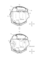
次に、本実施例の可変演出ユニット140(可変演出装置)の構成について図44を参照しながら説明する。同図に示すように、可変演出ユニット140は主に、真ん中が開口した略ロの字型のフレーム141と、フレーム141に組み付けられる可変演出部材14と、可変演出部材14を作動させる駆動手段(図5を参照)としてのモータ(図示せず)と、を含んで構成される。この可変演出ユニット140は、遊技盤2の後方(裏面)に不図示の取り付けベースを介してネジ止め等により組み付けられる。そして、可変演出ユニット140の裏面(後方)には、不図示の取り付けベースを介して画像表示装置7(液晶表示器)が、その表示画面7aをフレーム141の開口Aに臨ませてネジ止め等により組み付けられる。
[Configuration of variable production unit]
Next, the configuration of the variable presentation unit 140 (variable presentation device) of this embodiment will be explained with reference to FIG. 44. As shown in the figure, the
遊技盤2の後方(裏面)に組み付けられた可変演出ユニット140のフレーム141は、遊技盤2、センター装飾体10及びカバー部材17等に隠れて外部に露呈しないようになっており、遊技者には(前方からは)見えないようになっている。そして、フレーム141の開口Aは、センター装飾体10の中央開口と重なるので、これにより画像表示装置7の表示画面7aが、センター装飾体10及びフレーム141の夫々の開口を介して前方から視認可能とされる(図3を参照)。
The
図44に示すように、フレーム141の上下左右の4辺のうち左右の2辺には、それぞれ上下方向に延びる案内孔142L,142R(左右一対の案内孔)が設けられている。案内孔142Lには、左可変演出部材14Lを支持する軸体143Lが案内孔142Lに沿って移動可能に配されており、案内孔142Rには、右可変演出部材14Rを支持する軸体143Rが案内孔142Rに沿って移動可能に配されている。軸体143L,143Rは、何れも前後方向を向いて設けられている。案内孔142L及び案内孔142Rの何れか一方又は両方を指して「案内孔」(案内孔142)ともいう。
As shown in FIG. 44, guide
可変演出ユニット140は、左可変演出部材14Lを作動させるモータ(駆動手段)として、左可変演出部材14Lを上下動させる第1のモータ(図示せず)と、左可変演出部材14Lを回動させる第2のモータ(図示せず)とを備えており、右可変演出部材14Rを作動させるモータ(駆動手段)として、右可変演出部材14Rを上下動させる第3のモータ(図示せず)と、右可変演出部材14Rを回動させる第4のモータ(図示せず)とを備えている。これら4つのモータは、何れもステッピングモータとすることができる。
The
第1のモータの駆動(正回転駆動又は逆回転駆動)により、軸体143Lが案内孔142Lに沿って上下方向に移動し、これに伴って左可変演出部材14Lが上下動する。これにより左可変演出部材14Lは、案内孔142Lにより許容される上下方向の移動範囲内で変位可能となる。案内孔142L内(左可変演出部材14Lの移動範囲内)には、左可変演出部材14Lの始点位置、中間点位置及び終点位置が設けられており、それぞれの位置に左可変演出部材14Lが位置するときに、第2のモータの駆動(正回転駆動又は逆回転駆動)により、左可変演出部材14Lが軸体143Lを回動軸として、起立状態と右側へ約90度倒れた状態(傾倒状態)との間で回動(往復回動)する。前述のように、左可変演出部材14Lが起立状態にあるとき、左可変演出部材14Lは左カバー部材17Lの後方に隠れて前方から視認することが困難となり(図3を参照)、傾倒状態になることで、左可変演出部材14Lの旗部14aLが前方から視認可能となる。
By driving the first motor (forward rotation drive or reverse rotation drive), the
第3のモータの駆動(正回転駆動又は逆回転駆動)により、軸体143Rが案内孔142Rに沿って上下方向に移動し、これに伴って右可変演出部材14Rが上下動する。これにより右可変演出部材14Rは、案内孔142Rにより許容される上下方向の移動範囲内で変位可能となる。案内孔142R内(右可変演出部材14Rの移動範囲内)には、右可変演出部材14Rの始点位置、中間点位置及び終点位置が設けられており、それぞれの位置に右可変演出部材14Rが位置するときに、第4のモータの駆動(正回転駆動又は逆回転駆動)により、右可変演出部材14Rが軸体143Rを回動軸として、起立状態と左側へ約90度倒れた状態(傾倒状態)との間で回動(往復回動)する。前述のように、右可変演出部材14Rが起立状態にあるとき、右可変演出部材14Rは右カバー部材17Rの後方に隠れて前方から視認することが困難となり(図3を参照)、傾倒状態になることで、右可変演出部材14Rの旗部14aRが前方から視認可能となる。
By driving the third motor (forward rotation drive or reverse rotation drive), the
左右の可変演出部材14L,14Rの各始点位置、中間点位置及び終点位置には、それぞれ不図示の位置検知センサが設けられており、各位置検知センサの信号(検知信号)が、後述の副制御基板90に入力されるようになっている。これにより、副制御基板90に実装された後述の演出制御用マイコン91は、左右の案内孔142L,142Rに沿って移動(上下動)する可変演出部材14L,14Rの位置を検知することが可能となっている。なお、始点位置、中間点位置及び終点位置のうち、始点位置のことを「非作動位置」ともいい、中間点位置や終点位置のことを「作動位置」ともいう。
A position detection sensor (not shown) is provided at each of the start, middle and end positions of the left and right
なお、左右の可変演出部材14L,14Rを回動させるための駆動手段として、モータ(第2のモータ、第4のモータ)に替えてソレノイドを採用することも可能である。
Note that it is also possible to employ a solenoid instead of the motor (second motor, fourth motor) as a driving means for rotating the left and right
[パチンコ遊技機1の電気的構成]
次に図2及び図5に基づいて、本パチンコ遊技機1の電気的な構成を説明する。本実施例のパチンコ遊技機1は、特別図柄当否判定や普通図柄当否判定や遊技状態の移行など、遊技の進行や遊技利益に関する制御を行う主制御基板(「主制御部」又は「遊技制御部」ともいう。)80、遊技の進行に伴って実行する演出に関する制御を行う副制御基板(「サブ制御部」又は「演出制御部」ともいう。)90、遊技球の払い出しに関する制御を行う払出制御基板(「払出制御部」ともいう。)110、画像表示装置7の表示制御を行う画像制御基板(「画像制御部」ともいう。)100等を備えている。
[Electrical configuration of pachinko gaming machine 1]
Next, the electrical configuration of the
図2に示すように、パチンコ遊技機1の背面側(裏面側)には、その略中央部に主制御基板80を収納した主制御基板収納ケースが設けられ、主制御基板ケースの上方に、音声制御基板106、ランプ制御基板107及び画像制御基板100を収納した画像制御基板等収納ケースが設けられ、画像制御基板等収納ケース上に副制御基板90を収納した副制御基板収納ケースが設けられている。また、主制御基板ケースの下方左側に、払出制御基板110を収納した払出制御基板ケースが設けられ、払出制御基板ケースの右側に、電源基板109を収納した電源基板ケースが設けられている。
As shown in FIG. 2, on the back side (back side) of the
図5に示すように、主制御基板80には、プログラムに従ってパチンコ遊技機1の遊技の進行を制御する遊技制御用ワンチップマイコン(「遊技制御用マイコン」ともいう。)81が実装されている。遊技制御用マイコン81には、遊技の進行を制御するためのプログラム等を記憶したROM、ワークメモリとして使用されるRAM、ROMに記憶されたプログラムを実行するCPUが含まれている。
As shown in FIG. 5, a one-chip microcomputer for game control (also referred to as a "microcomputer for game control") 81 is mounted on the
遊技制御用マイコン81は、入出力回路87(I/Oポート部)を介して他の基板等とデータ(情報)の送受信を行う。入出力回路87は、遊技制御用マイコン81に内蔵されていてもよい。また、ROMは外付けであってもよい。主制御基板80(遊技制御用マイコン81)のROMには、遊技進行に係る各種の判定や決定(選択)に用いるテーブルや、特別図柄や普通図柄の変動パターン、第2始動口21や大入賞口30の開放パターンなど、遊技の進行を制御するのに必要な各種のデータが記憶されている。
The
遊技制御用マイコン81のRAMには、前述した特図保留記憶部(第1特図保留記憶部及び第2特図保留記憶部)や普図保留記憶部等が設けられている。また、主制御基板80(遊技制御用マイコン81)のRAM(主制御RAM)の所定アドレスには、各種フラグや各種計数カウンタに用いるための記憶領域が確保されている。
The RAM of the
主制御基板80には、中継基板88を介して各種センサやソレノイドが接続されている。そのため、主制御基板80には各センサから信号が入力され、各ソレノイドには主制御基板80から信号が出力される。具体的には、遊技球を検知可能なセンサ類として、第1始動口センサ20a、第2始動口センサ21a、ゲートセンサ28a、大入賞口センサ30aおよび一般入賞口センサ27aが接続されている。これら各種センサのことを「球検知センサ」や「遊技球検知手段」ともいう。
Various sensors and solenoids are connected to the
球検知センサは、例えば、検知コイルとこの検知コイルにベース又はゲートが接続されたトランジスタとを備えたものとされており、遊技球が検知コイル内を通過した場合に検知コイルのインピーダンス(電気抵抗)が変化することを利用して出力トランジスタの状態を変化させることで、遊技球を検知している間は、例えば、トランジスタの出力をHレベルからLレベルに変化させ得るように構成されている。 A ball detection sensor is, for example, equipped with a detection coil and a transistor whose base or gate is connected to the detection coil, and when a game ball passes through the detection coil, the impedance (electrical resistance) of the detection coil is ) is changed to change the state of the output transistor, so that the output of the transistor can be changed from, for example, an H level to an L level while a game ball is being detected. .
第1始動口センサ20aは、第1始動口20内に設けられて第1始動口20に入球した遊技球を検知するものである。第2始動口センサ21aは、第2始動口21内に設けられて第2始動口21に入球した遊技球を検知するものである。ゲートセンサ28aは、ゲート28内に設けられてゲート28を通過した遊技球を検知するものである。大入賞口センサ30aは、大入賞口30内に設けられて大入賞口30に入球した遊技球を検知するものである。一般入賞口センサ27aは、各一般入賞口27内にそれぞれ設けられて一般入賞口27に入球した遊技球を検知するものである。
The first
ソレノイド類としては、第2始動口ソレノイド24および大入賞口ソレノイド33が接続されている。これら各種ソレノイドを「駆動手段」ともいう。第2始動口ソレノイド24は、可変入賞装置22の可動部材23を駆動するためのものである。大入賞口ソレノイド33は、大入賞装置31の開閉部材32を駆動するためのものである。
As the solenoids, the second
また主制御基板80には、第1特別図柄表示器41a、第2特別図柄表示器41b、普通図柄表示器42、第1特図保留表示器43a、第2特図保留表示器43b、普図保留表示器44、ラウンド表示器45、遊技状態表示器46、発射方向表示器47および当り表示器48が接続されている。これらの主表示器40の表示制御は、遊技制御用マイコン81によりなされる。
The
主制御基板80は、払出制御基板110に各種コマンドを送信するとともに、払い出し監視のために払出制御基板110から信号を受信する。払出制御基板110には、賞球や貸球を払い出す払出装置120、及びカードユニット135(パチンコ遊技機1に隣接して設置され、挿入されたプリペイドカード(遊技価値記憶媒体)等に記憶されている情報に基づいて球貸しを可能にするもの)が接続されているとともに、発射制御基板(「発射制御回路」ともいう。)111を介して発射装置112が接続されている。発射装置112は、発射モータ113、タッチスイッチ114及び発射ボリューム115を含んで構成される。また発射装置112には、発射ハンドル60(図1を参照)が含まれる。
The
払出制御基板110は、所定のプログラムに従って遊技球の払い出しを制御する払出制御用ワンチップマイコン(「払出制御用マイコン」ともいう。)116が実装されている。払出制御用マイコン116には、遊技球の払い出しを制御するためのプログラム等を記憶したROM、ワークメモリとして使用されるRAM、ROMに記憶されたプログラムを実行するCPUが含まれている。
The
払出制御用マイコン116は、入出力回路117を介し、遊技制御用マイコン81からの信号やパチンコ遊技機1に接続されたカードユニット135からの信号に基づいて、払出装置120の払出モータ121を駆動して賞球や貸球の払い出しを行う。払い出される遊技球は、その計数のため払出センサ122,123により検知される。発射装置112の発射ハンドル60の操作があった場合には、その操作者(遊技者)による発射ハンドル60(回動操作部60a)への接触をタッチスイッチ114が検知し、発射ボリューム115が発射ハンドル60(回動操作部60a)の操作量(回動量)を検知する。そして、発射ボリューム115の検知信号の大きさに応じた強さ(発射強度)で遊技球が発射されるよう発射モータ113が駆動制御される。本実施例では、発射モータ113の駆動により発射装置112が連続して発射可能な遊技球の数が1分間で約100個となっている。
The
主制御基板80は、副制御基板90に対し各種コマンドを送信する。主制御基板80と副制御基板90との接続は、主制御基板80から副制御基板90への信号の送信のみが可能な単方向通信接続となっている。すなわち、主制御基板80と副制御基板90との間には、通信方向規制手段としての不図示の単方向性回路(例えばダイオードを用いた回路)が介在している。
The
図5に示すように、副制御基板90には、所定のプログラムに従ってパチンコ遊技機1の演出を制御する演出制御用ワンチップマイコン(「演出制御用マイコン」ともいう。)91が実装されている。演出制御用マイコン91には、遊技の進行に伴って行われる演出を制御するためのプログラム等を記憶したROM、ワークメモリとして使用されるRAM、ROMに記憶されたプログラムを実行するCPUが含まれている。
As shown in FIG. 5, the
演出制御用マイコン91は、入出力回路95を介して他の基板等とデータの送受信を行う。なお、入出力回路95は演出制御用マイコン91に内蔵されていてもよく、ROMは外付けであってもよい。副制御基板90(演出制御用マイコン91)のROMには、遊技演出に係る各種の判定や決定(選択)に用いるテーブルや、変動演出や予告演出等の演出パターンなど、演出を制御するのに必要な各種のデータが記憶されている。また、副制御基板90(演出制御用マイコン91)のRAM(演出制御RAM)の所定アドレスには、各種フラグや各種計数カウンタに用いるための記憶領域が確保されている。
The
副制御基板90には、画像制御基板100、音声制御基板106及びランプ制御基板107等が接続されている。副制御基板90(演出制御用マイコン91)は、遊技の状況に応じて画像制御基板100、音声制御基板106及びランプ制御基板107と協働して、表示演出や音演出、ランプ演出(光演出)等の各種演出を、対応する演出用の装置や部材等(演出手段)に実行させる。この副制御基板90(演出制御用マイコン91)は、遊技の状況に応じて種々の演出を実行させることが可能な演出実行手段(「演出制御手段」ともいう。)として機能する。なお、画像制御基板100、音声制御基板106及びランプ制御基板107のうち少なくとも一つを、副制御基板90とともに演出実行手段(演出制御手段)として機能するものと捉えることもできる。
An
副制御基板90(演出制御用マイコン91)は、主制御基板80から受信したコマンドに基づいて、画像制御基板100の画像制御用ワンチップマイコン(「画像制御用マイコン」ともいう。)101のCPUに画像表示装置7の表示制御を行わせる。
The sub-control board 90 (production control microcomputer 91) controls the CPU of the image control one-chip microcomputer (also referred to as "image control microcomputer") 101 of the
画像制御基板100のRAMは、画像データを展開するためのメモリである。画像制御基板100のROMには、画像表示装置7に表示される静止画データや動画データ、具体的にはキャラクタ、アイテム、図形、文字、数字および記号等(演出図柄、保留図柄等を含む)や背景画像等の各種画像データが格納されている。画像制御用マイコン101は、演出制御用マイコン91からの指令に基づいてROMから画像データを読み出す。そして、読み出した画像データに基づいて表示制御を実行する。なお、画像制御基板100の画像制御用ワンチップマイコン101に換えて又は加えて、VDP(Video Display Processor)を設けてもよい。
The RAM of the
副制御基板90(演出制御用マイコン91)は、主制御基板80から受信したコマンドに基づいて、音声制御基板106を介してスピーカ67から音声、楽曲、効果音等を出力する。スピーカ67から出力する音声等の音データは、副制御基板90のROMに格納されている。
The sub-control board 90 (production control microcomputer 91) outputs audio, music, sound effects, etc. from the
なお、音声制御基板106にCPUを実装してもよく、その場合、そのCPUに音声制御を実行させてもよい。さらにこの場合、音声制御基板106にROMを実装してもよく、そのROMに音データを格納してもよい。また、スピーカ67を画像制御基板100に接続し、画像制御用マイコン101に音声制御を実行させてもよい。この場合、画像制御基板100のROMに音データを格納してもよい。
Note that a CPU may be mounted on the
副制御基板90(演出制御用マイコン91)は、主制御基板80から受信したコマンドに基づいて、枠ランプ66や盤面ランプ5等のランプの発光態様を決める発光パターンデータ(点灯/消灯や発光色等を決めるデータであり、「ランプデータ」ともいう。)を、ROMに格納されているデータから決定し、ランプ制御基板107を介して枠ランプ66や盤面ランプ5等のランプ(LED)の点灯制御を行う。
Based on commands received from the
副制御基板90(演出制御用マイコン91)は、主制御基板80から受信したコマンドに基づいて、ランプ制御基板107に中継基板108を介して接続された可変演出部材14(左可変演出部材14L、右可変演出部材14R)を作動させる。前述したように可変演出部材14は、カバー部材17の後方に設けられた可動式の所謂ギミックである。演出制御用マイコン91は、可変演出部材14を所定の作動態様で作動させるためのデータ(「駆動データ」ともいう。)を、副制御基板90のROMに予め格納(記憶)されている複数の作動パターンデータの中から決定(選択)し、その決定した作動パターンデータに基づいて可変演出部材14の作動(ギミック演出)を制御する。
The sub-control board 90 (
なお、ランプ制御基板107にCPUを実装してもよく、その場合、そのCPUにランプの点灯制御や可変演出部材14の作動制御を実行させてもよい。さらにこの場合、ランプ制御基板107にROMを実装してもよく、そのROMに発光パターンや作動パターンに関するデータを格納してもよい。
Note that a CPU may be mounted on the
副制御基板90には、第1演出ボタン63aや第2演出ボタン63b(図1を参照)が操作(押す、回転、引く等)されたことを検知する第1演出ボタン検知スイッチ63cおよび第2演出ボタン検知スイッチ63dが接続されている。第1演出ボタン63aまたは第2演出ボタン63bに対して遊技者が所定の入力操作を行うと、対応する演出ボタン検知スイッチからの信号が副制御基板90に入力される。なお、第1演出ボタン検知スイッチ63cおよび第2演出ボタン検知スイッチ63dを総称して単に「演出ボタン検知スイッチ」ともいう。
The
[当りの概要]
次に、本パチンコ遊技機1の当りの概要(スペック)について説明する。本実施例では、特別図柄当否判定の結果として「大当り」と「外れ」がある。前述したように、「大当り」のときには特別図柄表示部に「大当り図柄」が停止表示され、「外れ」のときには特別図柄表示部に「外れ図柄」が停止表示される。特別図柄当否判定で大当りと判定されると、停止表示された特別図柄の種類(大当り種別)に応じた開放パターンにて大入賞口30を開放する「特別遊技」が実行される。大当りとなって実行される特別遊技のことを「大当り遊技」ともいう。
[Summary of winnings]
Next, the outline (specifications) of winnings of this
本実施例の大当りには複数の種別がある。具体的には、図6に示すように、大当りとして「10R(ラウンド)第1大当り」、「10R第2大当り」、「10R第3大当り」、「10R第4大当り」、「10R第5大当り」、「5R第6大当り」、「5R第7大当り」、「10R第8大当り」及び「10R第9大当り」の計9種類が設けられている。これらの大当りのうち、「10R第1大当り」、「10R第2大当り」、「10R第3大当り」、「10R第4大当り」、「10R第5大当り」、「5R第6大当り」及び「5R第7大当り」は第1特別図柄に係る大当りであり、「10R第8大当り」及び「10R第9大当り」は第2特別図柄に係る大当りである。特別図柄表示部には、これらの大当り種別に応じた大当り図柄が停止表示される。なお、本明細書ではラウンドを「R」と表記することがある。 There are multiple types of jackpots in this embodiment. Specifically, as shown in FIG. 6, the jackpots include "10R (round) 1st jackpot," "10R 2nd jackpot," "10R 3rd jackpot," "10R 4th jackpot," and "10R 5th jackpot." ”, “5R 6th jackpot”, “5R 7th jackpot”, “10R 8th jackpot” and “10R 9th jackpot” in total. Among these jackpots, "10R 1st jackpot", "10R 2nd jackpot", "10R 3rd jackpot", "10R 4th jackpot", "10R 5th jackpot", "5R 6th jackpot" and "5R 7th jackpot" is a jackpot related to the first special symbol, and "10R 8th jackpot" and "10R 9th jackpot" are jackpots related to the 2nd special symbol. In the special symbol display section, jackpot symbols corresponding to these jackpot types are stopped and displayed. Note that in this specification, a round may be expressed as "R".
10R第1大当り、10R第8大当り及び10R第9大当りは、何れもラウンド数が「10」、大入賞口30の開放回数が1R~10Rの各ラウンドにつき「1回」、大入賞口30の開放時間が1R~10Rの各ラウンドにつき「25秒」の大当りである。開放時間「25秒」の開放のことを「ロング開放」ともいう。
For the 10R 1st jackpot, 10R 8th jackpot, and 10R 9th jackpot, the number of rounds is "10", the number of openings of the
5R第6大当り及び5R第7大当りは、何れもラウンド数が「5」、大入賞口30の開放回数が1R~5Rの各ラウンドにつき「1回」、大入賞口30の開放時間が1R~5Rの各ラウンドにつき「25秒」の大当りである。
For both the 5R 6th jackpot and the 5R 7th jackpot, the number of rounds is "5", the number of openings of the big winning
10R第2大当りは、ラウンド数が「10」、大入賞口30の開放回数が1R~10Rの各ラウンドにつき「1回」、大入賞口30の開放時間が1R~10Rの各ラウンドにつき「25秒」の大当りである。 The 10R second jackpot has a number of rounds of "10", a number of openings of the grand prize opening 30 "once" for each round from 1R to 10R, and a time of opening of the grand prize opening 30 of "25" for each round of 1R to 10R. It was a jackpot of "Seconds".
10R第3大当りは、ラウンド数が「10」、大入賞口30の開放回数が1R~10Rの各ラウンドにつき「1回」、大入賞口30の開放時間が、1R~7Rの各ラウンドにつき「25秒」、8R~10Rの各ラウンドにつき「0.1秒」の大当りである。開放時間「0.1秒」の開放のことを「ショート開放」ともいう。10R第3大当りに係る大当り遊技(「10R第3大当り遊技」ともいう。)のうち、8R~10Rは大入賞口30の1ラウンドあたりの開放時間が「0.1秒」という極短時間であり、大入賞口30に遊技球が入球する可能性は極めて低いもの(実質的にゼロ)となる。このため、10R第3大当り遊技では、1ラウンドあたりの開放時間が「25秒」とされる1R~7Rにおいて大入賞口30への遊技球の入球可能性が高くなり、遊技球を容易に大入賞口30に入球させることが可能となる。したがって、10R第3大当りは実質的に「7R大当り」であり、10R第3大当り遊技は実質的に「7R大当り遊技」である。
For the 10R third jackpot, the number of rounds is ``10'', the number of openings of the
10R第4大当りは、ラウンド数が「10」、大入賞口30の開放回数が1R~10Rの各ラウンドにつき「1回」、大入賞口30の開放時間が、1R~5Rの各ラウンドにつき「25秒」、6R~10Rの各ラウンドにつき「0.1秒」の大当りである。10R第4大当りに係る大当り遊技(「10R第4大当り遊技」ともいう。)のうち、6R~10Rは大入賞口30の1ラウンドあたりの開放時間が「0.1秒」という極短時間であり、大入賞口30に遊技球が入球する可能性は極めて低いもの(実質的にゼロ)となる。このため、10R第4大当り遊技では、1ラウンドあたりの開放時間が「25秒」とされる1R~5Rにおいて大入賞口30への遊技球の入球可能性が高くなり、遊技球を容易に大入賞口30に入球させることが可能となる。したがって、10R第4大当りは実質的に「5R大当り」であり、10R第4大当り遊技は実質的に「5R大当り遊技」である。
For the 10R 4th jackpot, the number of rounds is "10", the number of openings of the
10R第5大当りは、ラウンド数が「10」、大入賞口30の開放回数が1R~10Rの各ラウンドにつき「1回」、大入賞口30の開放時間が、1R~3Rの各ラウンドにつき「25秒」、4R~10Rの各ラウンドにつき「0.1秒」の大当りである。10R第5大当りに係る大当り遊技(「10R第5大当り遊技」ともいう。)のうち、4R~10Rは、大入賞口30の1ラウンドあたりの開放時間が「0.1秒」という極短時間であり、大入賞口30に遊技球が入球する可能性は極めて低いもの(実質的にゼロ)となる。このため、10R第4大当り遊技では、1ラウンドあたりの開放時間が「25秒」とされる1R~3Rにおいて大入賞口30への遊技球の入球可能性が高くなり、遊技球を容易に大入賞口30に入球させることが可能となる。したがって、10R第5大当りは実質的に「3R大当り」であり、10R第5大当り遊技は実質的に「3R大当り遊技」である。
For the 10R 5th jackpot, the number of rounds is "10", the number of openings of the
これら9種類の大当りのうち、10R第1大当り、5R第6大当り、5R第7大当り、10R第8大当り及び10R第9大当りは、各ラウンドの間(ラウンド間)に一定のインターバル時間(例えば、約0.5秒~1秒)が設定され、1ラウンドから最終ラウンドまでの各ラウンドが同じ(一定の)インターバル時間を挟んで消化される。このようにラウンドが消化される10R第1大当り、5R第6大当り、5R第7大当り、10R第8大当り及び10R第9大当りは、一般的な大当りであるといえる。 Among these nine types of jackpots, the 10R 1st jackpot, 5R 6th jackpot, 5R 7th jackpot, 10R 8th jackpot, and 10R 9th jackpot have a certain interval time (for example, (approximately 0.5 seconds to 1 second), and each round from the first round to the final round is completed with the same (fixed) interval time in between. The 10R 1st jackpot, the 5R 6th jackpot, the 5R 7th jackpot, the 10R 8th jackpot, and the 10R 9th jackpot in which rounds are played in this way can be said to be general jackpots.
これに対し、10R第2大当り及び10R第3大当り(実質7R大当り)は、3ラウンド、5ラウンド及び7ラウンドが終了したときのラウンド間と、それ以外のラウンド(1R、2R、4R、6R、8R、9R)が終了したときのラウンド間とで、インターバル時間を異ならせており、前者の方が後者よりもインターバル時間が長くなっている。例えば、3ラウンド、5ラウンド及び7ラウンドが終了したときのラウンド間のインターバル時間は「約3秒~5秒」とされ、それ以外のラウンド(1R、2R、4R、6R、8R、9R)が終了したときのラウンド間のインターバル時間は「約0.5秒~1秒」とされる。 On the other hand, the 10R 2nd jackpot and 10R 3rd jackpot (actually 7R jackpot) occur between rounds when the 3rd round, 5th round, and 7th round are completed, and during the other rounds (1R, 2R, 4R, 6R, The interval time is different between the rounds when 8R and 9R) are completed, and the former is longer than the latter. For example, when the 3rd round, 5th round, and 7th round are completed, the interval time between rounds is "approximately 3 seconds to 5 seconds", and the other rounds (1R, 2R, 4R, 6R, 8R, 9R) are The interval time between rounds when the round ends is approximately 0.5 seconds to 1 second.
10R第4大当り(実質5R大当り)は、3ラウンド及び5ラウンドが終了したときのラウンド間と、それ以外のラウンド(1R、2R、4R、6R、7R、8R、9R)が終了したときのラウンド間とで、インターバル時間を異ならせており、前者の方が後者よりもインターバル時間が長くなっている。例えば、3ラウンド及び5ラウンドが終了したときのラウンド間のインターバル時間は「約3秒~5秒」とされ、それ以外のラウンド(1R、2R、4R、6R、8R、9R)が終了したときのラウンド間のインターバル時間(「第2インターバル時間」ともいう。)は「約0.5秒~1秒」とされる。 10R 4th jackpot (actually 5R jackpot) occurs between rounds when the 3rd and 5th rounds are completed, and when the other rounds (1R, 2R, 4R, 6R, 7R, 8R, 9R) are completed. The interval time is different between the two, with the former having a longer interval time than the latter. For example, when the 3rd round and 5th round are completed, the interval time between rounds is "approximately 3 seconds to 5 seconds", and when the other rounds (1R, 2R, 4R, 6R, 8R, 9R) are completed, The interval time between rounds (also referred to as "second interval time") is "approximately 0.5 seconds to 1 second".
10R第5大当り(実質3R大当り)は、3ラウンドが終了したときのラウンド間と、それ以外のラウンド(1R、2R、4R、5R、6R、7R、8R、9R)が終了したときのラウンド間とで、インターバル時間を異ならせており、前者の方が後者よりもインターバル時間が長くなっている。例えば、3ラウンドが終了したときのラウンド間のインターバル時間は「約3秒~5秒」とされ、それ以外のラウンド(1R、2R、4R、5R、6R、7R、8R、9R)が終了したときのラウンド間のインターバル時間は「約0.5秒~1秒」とされる。 10R 5th jackpot (actually 3R jackpot) is between rounds when 3 rounds are completed and between rounds when other rounds (1R, 2R, 4R, 5R, 6R, 7R, 8R, 9R) are completed. The interval times are different between the two, with the former having a longer interval time than the latter. For example, when 3 rounds are completed, the interval time between rounds is "approximately 3 to 5 seconds", and the other rounds (1R, 2R, 4R, 5R, 6R, 7R, 8R, 9R) are completed. The interval time between rounds is set to be approximately 0.5 seconds to 1 second.
10R第2~第5大当りにおいて、相対的に長いインターバル時間(例えば、約3秒~5秒)のことを「第1インターバル時間」ともいい、相対的に短いインターバル時間(例えば、約0.5秒~1秒)のことを「第2インターバル時間」ともいう。 In the 10R second to fifth jackpots, the relatively long interval time (for example, about 3 seconds to 5 seconds) is also called the "first interval time", and the relatively short interval time (for example, about 0.5 seconds) is also called the "first interval time". 1 second to 1 second) is also referred to as the "second interval time."
第1インターバル時間が設定されるラウンド間(「インターバル期間」ともいう。)では、次のラウンドも大入賞口30がロング開放されるか否か、すなわち、ロング開放のラウンドが実行(継続)されるか否かを示唆する演出が、画像表示装置7(表示画面7a)等を用いて実行される。第1インターバル時間が設定されるラウンド間のことを「ラウンド分岐タイミング」ともいい、ラウンド分岐タイミングにおいて実行される演出のことを「ラウンド分岐演出」ともいう。
Between the rounds where the first interval time is set (also referred to as the "interval period"), it is determined whether the
例えば、10R第5大当り遊技の3ラウンド目が終了したときのラウンド間(ラウンド分岐タイミング)では、ラウンド分岐演出として、次ラウンド以降、ロング開放のラウンドが実行(継続)されない旨を示唆する演出(例えば、ロング開放ラウンド終了演出や大当り終了演出)が実行され、10R第2~第4大当り遊技の3ラウンド目が終了したときのラウンド間(ラウンド分岐タイミング)では、ラウンド分岐演出として、次ラウンド以降もロング開放のラウンドが実行(継続)される旨を示唆する演出(例えば、ロング開放ラウンド継続演出)が実行される。 For example, between rounds (round branching timing) when the third round of a 10R 5th jackpot game ends, the round branching effect is an effect that suggests that the long open round will not be executed (continued) from the next round onwards. For example, between rounds (round branch timing) when a long open round end effect or jackpot end effect) is executed and the third round of the 10R 2nd to 4th jackpot game is completed, as a round branch effect, from the next round onwards. Also, an effect indicating that a long open round will be executed (continued) (for example, a long open round continuation effect) is executed.
また、10R第4大当り遊技の5ラウンド目が終了したときのラウンド間(ラウンド分岐タイミング)では、ラウンド分岐演出として、次ラウンド以降、ロング開放のラウンドが実行(継続)されない旨を示唆する演出(例えば、ロング開放ラウンド終了演出や大当り終了演出)が実行され、10R第2・第3大当り遊技の5ラウンド目が終了したときのラウンド間(ラウンド分岐タイミング)では、ラウンド分岐演出として、次ラウンド以降もロング開放のラウンドが実行(継続)される旨を示唆する演出(例えば、ロング開放ラウンド継続演出)が実行される。 In addition, between rounds (round branching timing) when the 5th round of the 10R 4th jackpot game ends, as a round branching effect, a production that suggests that the long open round will not be executed (continued) from the next round onwards ( For example, between rounds (round branch timing) when a long open round end effect or jackpot end effect) is executed and the 5th round of the 10R second and third jackpot games is completed, as a round branch effect, from the next round onwards. Also, an effect indicating that a long open round will be executed (continued) (for example, a long open round continuation effect) is executed.
また、10R第3大当り遊技の7ラウンド目が終了したときのラウンド間(ラウンド分岐タイミング)では、ラウンド分岐演出として、次ラウンド以降、ロング開放のラウンドが実行(継続)されない旨を示唆する演出(例えば、ロング開放ラウンド終了演出や大当り終了演出)が実行され、10R第2大当り遊技の7ラウンド目が終了したときのラウンド間(ラウンド分岐タイミング)では、ラウンド分岐演出として、次ラウンド以降もロング開放のラウンドが実行(継続)される旨を示唆する演出(例えば、ロング開放ラウンド継続演出)が実行される。 In addition, between rounds (round branching timing) when the 7th round of the 10R 3rd jackpot game ends, as a round branching effect, a production that suggests that the long open round will not be executed (continued) from the next round onwards ( For example, between rounds (round branch timing) when a long open round end effect or jackpot end effect) is executed and the 7th round of the 10R second jackpot game ends (round branch timing), the long open round effect will also be held from the next round onwards as a round branch effect. An effect (for example, a long open round continuation effect) indicating that the round will be executed (continued) is executed.
このように10R第2~第5大当りは、ロング開放のラウンドが継続するか否かの分岐点(ラウンド分岐タイミング)となるラウンド間において、それ以外のラウンド間に比して長時間のインターバル時間(第1インターバル時間)が設定され、当該インターバル時間を利用してラウンド分岐演出が実行されるものとなっている。このように、ラウンド分岐タイミングにおいてラウンド分岐演出が実行される10R第2~第5大当りに係る大当り遊技は所謂「ランクアップボーナス」と呼ばれるもので、10R第1大当り等の一般的な大当りとは遊技性が異なる特殊な大当りである。以下、ランクアップボーナスのことを「RUB」と表記することもある。 In this way, the 10R 2nd to 5th jackpots have a longer interval time than other rounds between rounds, which is the turning point (round branch timing) that determines whether or not the long open round continues. (first interval time) is set, and the round branch effect is executed using the interval time. In this way, the jackpot games related to the 10R 2nd to 5th jackpots in which the round branch effect is executed at the round branch timing are called "rank up bonuses", and are different from general jackpots such as the 10R 1st jackpot. This is a special jackpot with different gameplay. Hereinafter, the rank-up bonus may be referred to as "RUB".
ここで、ラウンドのことを「ラウンド遊技」ともいい、ラウンド遊技のことを「大入賞口開閉遊技」、「可変入球遊技」又は「特別入球遊技」ともいう。また、5R第6大当り及び5R第7大当りのことを総じて「5R大当り」ともいい、10R第1~第5大当り及び10R第8・第9大当りのことを総じて「10R大当り」ともいう。さらに、10R第2~第5大当りのことを「特殊大当り」ともいい、10R第2~第5大当り以外の大当り(10R第1・第8・第9大当り、5R第6・第7大当り)のことを「一般大当り」ともいい、特殊大当りに係る大当り遊技(ランクアップボーナス(RUB))のことを「第1特別遊技」ともいい、一般大当りに係る大当り遊技(5R大当り遊技又は10R大当り遊技)のことを「第2特別遊技」ともいう。 Here, the round is also referred to as a "round game," and the round game is also referred to as a "big prize opening/closing game," a "variable ball entry game," or a "special ball entry game." Further, the 5R 6th jackpot and 5R 7th jackpot are collectively referred to as the "5R jackpot", and the 10R 1st to 5th jackpots and the 10R 8th and 9th jackpots are also collectively referred to as the "10R jackpot". Furthermore, the 10R 2nd to 5th jackpots are also called "special jackpots", and jackpots other than the 10R 2nd to 5th jackpots (10R 1st, 8th, and 9th jackpots, 5R 6th and 7th jackpots) This is also called a "general jackpot", and the jackpot game (rank up bonus (RUB)) related to a special jackpot is also called the "first special game", which is a jackpot game related to a general jackpot (5R jackpot game or 10R jackpot game). This is also called the "second special game."
また、大当り遊技の実行契機となる特別図柄の大当り図柄(特定表示態様、特定表示結果)のうち、特殊大当りに係る大当り図柄(10R第2大当り図柄、10R第3大当り図柄、10R第4大当り図柄、10R第5大当り図柄)のことを「第1特定表示態様」又は「第1特定表示結果」ともいい、一般大当りに係る大当り図柄(10R第1大当り図柄、5R第6大当り図柄、5R第7大当り図柄、10R第8大当り図柄、10R第9大当り図柄)のことを「第2特定表示態様」又は「第2特定表示結果」ともいう。 Also, among the special jackpot symbols (specific display mode, specific display result) that trigger the execution of the jackpot game, the jackpot symbols related to the special jackpot (10R second jackpot symbol, 10R third jackpot symbol, 10R fourth jackpot symbol) , 10R 5th jackpot symbol) is also referred to as the "first specific display mode" or "first specific display result", and the jackpot symbols related to general jackpots (10R 1st jackpot symbol, 5R 6th jackpot symbol, 5R 7th jackpot symbol) are also referred to as "first specific display mode" or "first specific display result". The jackpot symbol, the 10R 8th jackpot symbol, the 10R 9th jackpot symbol) are also referred to as a "second specific display mode" or "second specific display result."
なお、本実施例では、ラウンド数の違いによる大当り種別を、5R大当り及び10R大当りの2種類としているが、例えば、3R大当りと6R大当りと10R大当りの3種類としたり、7R大当りの1種類としたりする等、種々の大当り種別を設けることが可能である。また本実施例では、大当り遊技の最大ラウンド数を10R(10R大当り)としているが、最大ラウンド数はこれに限られず、例えば、10Rよりも多いラウンド(例えば15R)を最大ラウンド数としたり、10Rよりも少ないラウンド(例えば9R)を最大ラウンド数としたりすることも可能である。 In this embodiment, there are two types of jackpots depending on the number of rounds: 5R jackpot and 10R jackpot, but for example, there may be three types: 3R jackpot, 6R jackpot, and 10R jackpot, or one type of 7R jackpot. It is possible to provide various types of jackpots, such as. Further, in this embodiment, the maximum number of rounds in the jackpot game is 10R (10R jackpot), but the maximum number of rounds is not limited to this, and for example, the maximum number of rounds may be more than 10R (for example, 15R), or 10R. It is also possible to set the maximum number of rounds to fewer rounds (for example, 9R).
本実施例のパチンコ遊技機1では、発生(当選)した大当りの種別に応じて、その大当り遊技の終了後の遊技状態を、後述の高確率状態や時短状態、高ベース状態等に移行させる。すなわち、特別図柄当否判定の結果が大当りで、その大当りの種別が前述の10R第1~第5大当り、5R第6大当り及び10R第8大当りの何れかである場合には、大当り遊技終了後の遊技状態が後述の「高確率状態かつ時短状態かつ高ベース状態」に制御される(図6を参照)。これに対して、特別図柄当否判定の結果が大当りで、その大当りの種別が前述の5R第7大当り及び10R第9大当りの何れかである場合には、大当り遊技終了後の遊技状態が後述の「低確率状態かつ時短状態かつ高ベース状態」に制御される(図6を参照)。このことから、10R第1~第5大当り、5R第6大当り及び10R第8大当りは「確変大当り」として捉えることができ、5R第7大当り及び10R第9大当りは「非確変大当り」(「通常大当り」又は「時短大当り」ともいう。)として捉えることができる。
In the
図6及び図8(B)に示すように、第1特別図柄(特図1)の当否判定で大当りとなった場合の各大当りの振分確率は、10R第1大当りが5%、10R第2大当りが5%、10R第3大当りが7%、10R第4大当りが10%、10R第5大当りが13%、5R第6大当りが15%、5R第7大当りが45%となっている。これに対して、第2特別図柄(特図2)の当否判定で大当りとなった場合の各大当りの振分確率は、10R第8大当りが55%、10R第9大当りが45%となっている。すなわち、第2始動口21への入球に基づく当否判定(特図2当否判定)で大当りとなった場合には、10R大当りの出現率(振分確率)が100%となっており、第1始動口20への入球に基づく当否判定(特図1当否判定)で大当りとなった場合に比べ、10R大当りの出現率(振分確率)が高くなっている。このように本パチンコ遊技機1では、第1始動口20に遊技球が入球して行われる当否判定(特図1当否判定)で大当りとなるよりも、第2始動口21に遊技球が入球して行われる当否判定(特図2当否判定)で大当りとなる方が、獲得可能な賞球量(賞球数)の観点で遊技者にとって有利となる可能性が高くなるように設定されている。このため遊技者は、第2始動口21への入球を期待して遊技を行う。特に第2始動口21への入球頻度が高まる後述の開放延長機能の作動中(高ベース状態の発生中)においては顕著である。
As shown in FIGS. 6 and 8(B), when the first special symbol (special symbol 1) is judged to be a jackpot, the distribution probability of each jackpot is 5% for the 10R first jackpot, 5% for the 10R first jackpot, and 5% for the 10R first jackpot. 2nd jackpot is 5%, 10R 3rd jackpot is 7%, 10R 4th jackpot is 10%, 10R 5th jackpot is 13%, 5R 6th jackpot is 15%, and 5R 7th jackpot is 45%. On the other hand, when the second special symbol (special symbol 2) is determined to be a jackpot, the distribution probability of each jackpot is 55% for the 10R 8th jackpot and 45% for the 10R 9th jackpot. There is. In other words, if the jackpot is determined based on the ball entering the second starting port 21 (Special Figure 2 Judgment), the appearance rate (distribution probability) of the 10R jackpot is 100%, and the The occurrence rate (distribution probability) of the 10R jackpot is higher than when a jackpot is achieved by the judgment based on the ball entering the 1 starting hole 20 (special figure 1 judgment). In this way, in this
本パチンコ遊技機1では、大当りか外れかの判定は「特別図柄当否判定用乱数(「当否判定用情報」ともいう。)」に基づいて行われ、当否判定の結果が大当りである場合の大当りの種別の判定は「大当り種別決定用乱数(「図柄決定用乱数」又は「図柄決定用情報」ともいう。)」に基づいて行われる。本実施例では、図7(A)に示すように、特別図柄当否判定用乱数は「0~629」までの範囲で値をとり、大当り種別決定用乱数は「0~99」までの範囲で値をとる。特別図柄当否判定用乱数および大当り種別決定用乱数は、第1始動口20や第2始動口21への入球に基づいて取得される乱数(取得情報)である。
In this
第1始動口20や第2始動口21への入球に基づいて取得される乱数(取得情報)には、特別図柄当否判定用乱数および大当り種別決定用乱数の他、図7(A)に示すように「変動パターン乱数(「変動パターン情報」ともいう。)」がある。変動パターン乱数は、変動時間を含む変動パターンを決めるための乱数であり、本実施例では「0~198」までの範囲で値をとる。
The random numbers (acquired information) acquired based on the ball entering the
また、ゲート28の通過に基づいて取得される乱数(取得情報)には、図7(B)に示す普通図柄当否判定用乱数がある。普通図柄当否判定用乱数は、第2始動口21を開放させる補助遊技を行うか否かの判定(普通図柄抽選)のための乱数であり、本実施例では「0~240」までの範囲で値をとる。
Further, the random numbers (acquired information) acquired based on passage through the
[遊技状態]
次に、本パチンコ遊技機1の遊技状態について説明する。パチンコ遊技機1は、特別図柄の確率変動機能及び変動時間短縮機能、普通図柄の確率変動機能及び変動時間短縮機能並びに普通電動役物の開放延長機能の各機能が作動状態または非作動状態となる組合せにより、複数の遊技状態を有している。特別図柄(第1特別図柄及び第2特別図柄)について確率変動機能が作動している状態を「高確率状態」や「確変状態」ともいい、作動していない状態を「低確率状態」や「通常状態」ともいう。
[Game status]
Next, the gaming state of the
高確率状態では、特別図柄当否判定において大当りと判定される確率が通常状態(低確率状態)よりも高くなっている。すなわち、通常状態では通常状態用の大当り判定テーブルを用いて当否判定を行うものの、高確率状態では、大当りと判定される特別図柄当否判定用乱数の値が多い高確率状態用の大当り判定テーブルを用いて、当否判定を行う(図8(A)を参照)。つまり、特別図柄の確率変動機能が作動すると、作動していないときに比して、特別図柄の変動表示の結果が大当りとなる(停止図柄が大当り図柄となる)確率が高くなる。 In the high probability state, the probability of being judged as a jackpot in the special symbol validity determination is higher than in the normal state (low probability state). That is, in the normal state, the jackpot determination table for the normal state is used to determine the success or failure, but in the high probability state, the jackpot determination table for the high probability state is used, in which there are many values of random numbers for special symbol validity determination that are determined to be jackpots. (See FIG. 8(A)). In other words, when the special symbol probability variation function is activated, the probability that the result of the special symbol variation display will be a jackpot (the stopped symbol will become a jackpot symbol) becomes higher than when it is not activated.
また、特別図柄(第1特別図柄および第2特別図柄)について変動時間短縮機能が作動している状態を「時短状態」や「短縮変動状態」ともいい、作動していない状態を「非時短状態」や「通常変動状態」ともいう。時短状態では、特別図柄の変動時間(変動表示の開始から終了(確定表示)までの時間)の平均値が、非時短状態における特別図柄の変動時間の平均値よりも短くなっている。すなわち、時短状態においては、変動時間の短い変動パターンが選択されることが非時短状態よりも多くなるように定められた変動パターンテーブルを用いて、変動パターンの判定を行う(図9を参照)。その結果、時短状態では、特図保留の消化ペースが速くなり、始動口への有効な入球(特図保留として記憶され得る入球)が発生しやすくなる。そのため、スムーズな遊技の進行のもとで大当りを狙うことができる。 In addition, the state in which the variable time reduction function is activated for the special symbols (first special symbol and second special symbol) is also referred to as a "time reduction state" or "reduction fluctuation state," and the state in which it is not activated is referred to as a "non-time reduction state." ” or “normal fluctuation state”. In the time-saving state, the average value of the fluctuation time of the special symbols (time from the start of the fluctuation display to the end (determined display)) is shorter than the average value of the fluctuation time of the special symbols in the non-time-saving state. That is, in the time-saving state, the fluctuation pattern is determined using a fluctuation pattern table that is determined so that a fluctuation pattern with a short fluctuation time is selected more often than in the non-time-saving state (see FIG. 9). . As a result, in the time-saving state, the pace at which the special figure reservation is consumed becomes faster, and effective ball entry into the starting port (ball entry that can be stored as special figure reservation) is more likely to occur. Therefore, players can aim for a jackpot while the game progresses smoothly.
特別図柄(第1特別図柄および第2特別図柄)の確率変動機能と変動時間短縮機能とは同時に作動することもあるし、片方のみが作動することもある。そして、普通図柄の確率変動機能および変動時間短縮機能は、特別図柄の変動時間短縮機能に同期して作動するようになっている。すなわち、普通図柄の確率変動機能および変動時間短縮機能は、特別図柄の時短状態において作動し、非時短状態において作動しないものとなっている。このため、時短状態では、普通図柄当否判定の当り確率が非時短状態よりも高くなる。具体的に時短状態では、当りと判定される普通図柄乱数(当り乱数)の値が非時短状態で用いる普通図柄当り判定テーブルよりも多い普通図柄当り判定テーブルを用いて、普通図柄当否判定(普通図柄の判定)を行う(図8(C)を参照)。 The probability variation function and the variation time reduction function of the special symbols (first special symbol and second special symbol) may operate at the same time, or only one of them may operate. The probability fluctuation function and the fluctuation time shortening function of the normal symbol operate in synchronization with the fluctuation time shortening function of the special symbol. That is, the probability variation function and variation time reduction function of the normal symbol operate in the time saving state of the special symbol, and do not operate in the non-time saving state. Therefore, in the time-saving state, the probability of winning in the normal symbol validity determination is higher than in the non-time-saving state. Specifically, in the time-saving state, a normal symbol hit/fail determination table is used that has a larger number of normal symbol random numbers (hit random numbers) that are determined to be hits than the normal symbol hit determination table used in the non-time-shortened state. symbol determination) (see FIG. 8(C)).
また時短状態では、普通図柄の変動時間が非時短状態よりも短くなっている。本実施例では、普通図柄の変動時間は非時短状態では30秒であるが、時短状態では1秒である(図8(D)を参照)。さらに時短状態では、可変入賞装置22(第2始動口21)の開放時間延長機能が作動し、補助遊技(普図当り遊技)における第2始動口21の開放時間が非時短状態よりも長くなっている。加えて時短状態では、可変入賞装置22の開放回数増加機能が作動し、補助遊技における第2始動口21の開放回数が非時短状態よりも多くなっている。具体的には、非時短状態において普通図柄当否判定の結果が当りになると、可変入賞装置22(第2始動口21)の可動部材23が0.2秒の開放動作を1回行い、時短状態において普通図柄当否判定の結果が当りになると、可変入賞装置22(第2始動口21)の可動部材23が2.0秒の開放動作を3回行うものとなっている。
Also, in the time saving state, the fluctuation time of the normal symbol is shorter than in the non-time saving state. In this embodiment, the variation time of the normal symbol is 30 seconds in the non-time saving state, but is 1 second in the time saving state (see FIG. 8(D)). Furthermore, in the time-saving state, the opening time extension function of the variable prize winning device 22 (second starting port 21) is activated, and the opening time of the
普通図柄についての確率変動機能および変動時間短縮機能、並びに、可変入賞装置22の開放時間延長機能および開放回数増加機能が作動している状況下では、これらの機能が作動していない場合に比して、第2始動口21が頻繁に開放され、第2始動口21へ遊技球の入球頻度が高くなる。その結果、発射球数に対する賞球数の割合であるベースが高くなる。従って、これらの機能が作動している状態を「高ベース状態」又は「高頻度状態」ともいい、作動していない状態を「低ベース状態」ともいう。高ベース状態では、手持ちの遊技球(持ち球)を大きく減らすことなく大当りを狙うことができる。
Under the situation where the probability fluctuation function and fluctuation time shortening function for normal symbols, and the opening time extension function and opening number increase function of the variable winning
なお、高ベース状態(高頻度状態)は、上記の全ての機能が作動するものでなくてもよい。すなわち、普通図柄についての確率変動機能および変動時間短縮機能、並びに、可変入賞装置22の開放時間延長機能および開放回数増加機能のうち少なくとも一つの機能の作動によって、その機能が作動していないときに比べ第2始動口21が開放され易く(入球頻度が高く)なるものであればよい。また本実施例では、特別図柄の時短状態と高ベース状態とを一緒に(同期させて)発生させるものとしているが、高ベース状態は、特別図柄の時短状態に付随せずに独立して発生させるようにしてもよい。この様な高ベース状態を発生させる機能のことを「高ベース発生機能」ともいい、開放時間延長機能および開放回数増加機能の何れか一方又は両方を指して「開放延長機能」ともいう。
Note that the high base state (high frequency state) does not need to be one in which all of the above functions are activated. That is, by operating at least one of the probability variation function and variation time shortening function for normal symbols, and the opening time extension function and opening number increase function of the variable winning
本実施例のパチンコ遊技機1では、前述したように、10R第1~5大当り、5R第6大当り及び10R第8大当りの何れかが発生した場合の大当り遊技後(特別遊技後)の遊技状態は、特別図柄の高確率状態かつ特別図柄の時短状態かつ高ベース状態となる(図6を参照)。この遊技状態を「高確高ベース状態」ともいう。高確高ベース状態は、予め定められた回数の特別図柄の変動表示が実行されるか、又は、大当りとなって大当り遊技が実行されることにより終了する。この高確高ベース状態は、遊技者にとっては所謂「確変状態」となる。
In the
また、5R第7大当り及び10R第9大当りの何れかが発生した場合の大当り遊技後(特別遊技後)の遊技状態は、特別図柄の通常状態(低確率状態)になるとともに、特別図柄の時短状態かつ高ベース状態となる(図6を参照)。この遊技状態を「低確高ベース状態」ともいう。低確高ベース状態は、所定回数(例えば100回)の特別図柄の変動表示が実行されるか、大当りに当選してその大当り遊技が実行されることにより終了する。 In addition, when either the 5R 7th jackpot or the 10R 9th jackpot occurs, the gaming state after the jackpot game (after the special game) will be the normal state (low probability state) of the special symbol, and the time saving state of the special symbol. state and high base state (see Figure 6). This gaming state is also referred to as a "low probability high base state". The low-probability-high base state ends when the variable display of special symbols is executed a predetermined number of times (for example, 100 times) or when a jackpot is won and the jackpot game is executed.
なお、「低確高ベース状態」のことを「第1遊技状態」ともいい、「高確高ベース状態」のことを「第2遊技状態」ともいう。また、本実施例のパチンコ遊技機1では、遊技状態として「低確低ベース状態」、「低確高ベース状態」、「高確高ベース状態」の3つの遊技状態を設定可能としているが、これに加え、特別図柄の高確率状態かつ特別図柄の非時短状態かつ低ベース状態、すなわち「高確低ベース状態」を設定可能としてもよい。
The "low probability high base state" is also referred to as the "first gaming state", and the "high probability high base state" is also referred to as the "second gaming state". Furthermore, in the
低確高ベース状態や高確高ベース状態といった高ベース状態では、右打ちにより遊技球を右遊技領域3Bへ進入させた方が有利に遊技を進行させることができる。高ベース状態では、低ベース状態と比べて第2始動口21が開放されやすくなっており、第1始動口20への入球よりも第2始動口21への入球の方が容易となっている(第1始動口よりも第2始動口の方が遊技球の入球可能性が高くなる)からである。このため、普通図柄当否判定の契機となるゲート28へ遊技球を通過させつつ、第2始動口21へ遊技球を入球させるべく右打ちを行う。これにより、左打ちを行う場合に比べ、多数の始動入球(特別図柄当否判定の機会)を得ることができる。この状態のとき、発射方向表示器47が所定の態様で点灯制御され、右遊技領域3Bを狙って遊技球を発射すべきことを報知する(右打ち指示報知)。
In a high base state such as a low probability high base state or a high probability high base state, the game can proceed more advantageously if the game ball enters the
これに対し、低ベース状態(例えば低確低ベース状態)では、左打ちにより左遊技領域3Aへ遊技球を進入させた方が有利に遊技を進行させることができる。低ベース状態では、高ベース状態と比べて第2始動口21が開放されにくくなっており、第2始動口21への入球よりも第1始動口20への入球の方が容易となっている(第2始動口よりも第1始動口の方が遊技球の入球可能性が高くなる)からである。そのため、第1始動口20へ遊技球を入球させるべく左打ちを行う。これにより、右打ちを行う場合に比べ、多数の始動入球(特別図柄当否判定の機会)を得ることができる。この状態のとき、発射方向表示器47が所定の態様で点灯制御(表示制御)され、左遊技領域3Aを狙って遊技球を発射すべきことを報知する(左打ち指示報知)。
On the other hand, in a low base state (for example, a low probability low base state), it is possible to advance the game more advantageously by making the game ball enter the
発射方向表示器47は「yz」の2個のLEDを有しており、遊技状態に応じてLEDを点灯させることにより発射方向を示すことが可能とされている。例えば、低ベース状態では、「y□z□」(例えば、□:消灯、■:点灯とする)というように両LEDを消灯する表示態様として左遊技領域へ発射すべきことを報知することができる。また、高ベース状態では、「y■z■」(例えば、□:消灯、■:点灯とする)というように両LEDを点灯する表示態様として右遊技領域へ発射すべきことを報知することができる。
The firing
以上のように本実施例のパチンコ遊技機1では、大当り遊技が行われていない低確低ベース状態を基準にすると、この低確低ベース状態を「通常遊技状態」として捉えることができ、当該状態にて特別図柄を変動表示させる遊技(変動遊技)を「通常遊技」として捉えることができる。一方、高確高ベース状態や低確高ベース状態は、低確低ベース状態に比べ遊技者にとって有利な遊技状態であることから、これら高確高ベース状態や低確高ベース状態を「特別遊技状態」として捉えることができ、当該状態にて特別図柄を変動表示させる遊技を「特別遊技」として捉えることができる。
As described above, in the
また、大当り遊技は、特別図柄を変動表示させて大当り図柄が停止表示されることで実行され得る遊技であって、遊技者にとっては、大入賞口(第1大入賞口30、第2大入賞口35)への遊技球の入球により多量の賞球を獲得できることから、大当り遊技が行われる遊技状態は、大当り遊技が行われていない遊技状態に比べ遊技者にとって有利な遊技状態であるといえる。このため、大当り遊技が行われる遊技状態を「特別遊技状態」として捉えることができ、当該状態にて行われる大当り遊技を「特別遊技」として捉えることができる。 In addition, the jackpot game is a game that can be executed by displaying special symbols in a variable manner and stopping displaying the jackpot symbol, and for the player, the jackpot game is a game that can be executed by displaying special symbols in a variable manner and stopping displaying the jackpot symbol. Since a large amount of prize balls can be won by entering the game ball into the opening 35), a gaming state in which a jackpot game is played is a gaming state that is more advantageous for the player than a gaming state in which a jackpot game is not played. I can say that. Therefore, the gaming state in which a jackpot game is played can be regarded as a "special game state", and the jackpot game played in this state can be regarded as a "special game".
また、低確低ベース状態や高確低ベース状態といった低ベース状態は、前述のように左打ちによって遊技球を左遊技領域3Aに進入させて遊技を進行させる遊技状態であることから、低ベース状態を「左打ち状態」として捉えることができる。一方、低確高ベース状態や高確高ベース状態といった高ベース状態および第1大入賞口30や第2大入賞口35への遊技球の入球を狙う大当り遊技が行われる状態は、前述のように右打ちによって遊技球を右遊技領域3Bに進入させて遊技を進行させる遊技状態であることから、高ベース状態や大当り遊技状態を「右打ち状態」として捉えることができる。そして、前述のように、高ベース状態(右打ち状態)では、低ベース状態(左打ち状態)に比べ第2始動口21が開放されやすく、第1始動口20よりも第2始動口21の方が遊技球の入球が容易となり、また、第1始動口20への遊技球の入球に基づく第1特別図柄の当否判定で大当りとなるよりも、第2始動口21への遊技球の入球に基づく第2特別図柄の当否判定で大当りとなる方が、遊技者にとって有利となる可能性が高くなるように設定されている。このため、左打ち状態を「通常遊技状態」として捉えることができ、当該状態にて特別図柄を変動表示させる遊技(変動遊技)を「通常遊技」として捉えることができる。また、左打ち状態に比べ遊技者にとって有利な遊技状態である右打ち状態を「特別遊技状態」として捉えることができ、当該状態にて特別図柄を変動表示させる遊技(変動遊技)を「特別遊技」として捉えることができる。
In addition, the low base states such as the low-accuracy low-base state and the high-accuracy low-base state are game states in which the game progresses by hitting the game ball to the left into the
また、高確低ベース状態は、低確低ベース状態と比較した場合、ともに低ベース状態である点では一致するものの、高確率状態では特別図柄の確率変動機能が作動して特別図柄の変動表示の結果が大当りとなる確率が低確率状態よりも高くなることから、低確低ベース状態に比べ遊技者にとって有利な遊技状態である高確低ベース状態を「特別遊技状態」として捉えることができ、当該状態にて特別図柄を変動表示させる遊技(変動遊技)を「特別遊技」として捉えることができる。 In addition, when comparing the high probability low base state with the low probability low base state, although they are both low base states, in the high probability state, the probability fluctuation function of the special symbol is activated and the special symbol is displayed fluctuating. Since the probability that the result will be a jackpot is higher than the low probability state, the high probability low base state, which is a gaming state more advantageous to the player than the low probability low base state, can be regarded as a "special gaming state". , A game in which special symbols are displayed in a variable manner in this state (variable game) can be regarded as a "special game."
以上の各種遊技状態の設定、移行等に係る制御は、主制御基板80(遊技制御用マイコン81)によって行われる。そして、確率変動機能の作動・非作動に係る制御を行う主制御基板80(遊技制御用マイコン81)は、特別図柄当否判定の当選確率(大当り確率)を低確率(第1確率)または高確率(第2確率)に設定可能な確率設定手段として機能する。また、変動時間短縮機能の作動・非作動に係る制御を行う主制御基板80(遊技制御用マイコン81)は、特別図柄の変動時間が通常よりも短くなる短縮変動状態(時短状態)を設定可能な短縮変動状態設定手段(時短状態設定手段)として機能する。 The control related to the settings, transitions, etc. of the various game states described above is performed by the main control board 80 (game control microcomputer 81). Then, the main control board 80 (game control microcomputer 81) that controls the activation/deactivation of the probability fluctuation function sets the winning probability (jackpot probability) of the special symbol correctness determination to a low probability (first probability) or a high probability. (second probability). In addition, the main control board 80 (game control microcomputer 81) that controls activation/deactivation of the fluctuation time reduction function can set a shortening fluctuation state (time saving state) in which the fluctuation time of special symbols is shorter than usual. It functions as a shortening fluctuation state setting means (time saving state setting means).
[主制御メイン処理]
次に、図10~図36に基づいて遊技制御用マイコン81(遊技制御手段)の動作(主制御部80による制御処理)について説明する。なお、遊技制御用マイコン81の動作説明にて登場するカウンタ、フラグ、ステータス、バッファ等は、主制御基板80のRAMに設けられている。また、本明細書においてS101等の「S」(フローチャート中の「S」)はステップを意味する。
[Main control main processing]
Next, the operation of the game control microcomputer 81 (game control means) (control processing by the main control unit 80) will be explained based on FIGS. 10 to 36. Note that the counters, flags, status, buffers, etc. that appear in the explanation of the operation of the
遊技制御用マイコン81は、パチンコ遊技機1の電源が投入(オン)されると、図10に示す主制御メイン処理のプログラムを主制御基板80のROMから読み出して実行する。同図に示すように、主制御メイン処理では、まず、初期設定を行う(S101)。初期設定では、例えば、スタックの設定、定数設定、割り込み時間の設定、主制御基板80のCPUの設定、SIO、PIO、CTC(割り込み時間用コントローラ)の設定や、各種のフラグ、ステータス及びカウンタのリセット等を行う。フラグの初期値は「0」つまり「OFF」であり、ステータスの初期値は「1」であり、カウンタの初期値は「0」である。初期設定(S101)は、電源投入後に一度だけ実行され、それ以降は実行されない。
When the power of the
初期設定(S101)に次いで、割り込みを禁止し(S102)、普通図柄・特別図柄主要乱数更新処理(S103)を実行する。普通図柄・特別図柄主要乱数更新処理(S103)では、図7に示した種々の乱数カウンタの値を1加算する更新を行う。各乱数カウンタの値は上限値に至ると「0」に戻って再び加算される。なお、各乱数カウンタの初期値は「0」以外の値であってもよく、ランダムに変更されるものであってもよい。更新された乱数カウンタ値は主制御基板80のRAMの所定の更新値記憶領域(図示せず)に逐次記憶される。
Following the initial setting (S101), interrupts are prohibited (S102), and normal symbol/special symbol main random number update processing (S103) is executed. In the normal symbol/special symbol main random number update process (S103), the values of the various random number counters shown in FIG. 7 are updated by adding one. When the value of each random number counter reaches the upper limit value, it returns to "0" and is added again. Note that the initial value of each random number counter may be a value other than "0" or may be changed randomly. The updated random number counter value is sequentially stored in a predetermined update value storage area (not shown) of the RAM of the
普通図柄・特別図柄主要乱数更新処理(S103)が終了すると、割り込みを許可する(S104)。割り込み許可中は、割り込み処理(S105)の実行が可能となる。割り込み処理(S105)は、例えば4ms周期で主制御基板80のCPUに繰り返し入力される割り込みパルスに基づいて実行される。そして、割り込み処理(S105)が終了してから、次に割り込み処理(S105)が開始されるまでの間に、普通図柄・特別図柄主要乱数更新処理(S103)による各種カウンタ値の更新処理が繰り返し実行される。なお、割り込み禁止状態のときにCPUに割り込みパルスが入力された場合は、割り込み処理(S105)はすぐには開始されず、割り込み許可(S104)がされてから開始される。
When the normal symbol/special symbol main random number update process (S103) is completed, an interrupt is permitted (S104). While interrupts are enabled, interrupt processing (S105) can be executed. The interrupt process (S105) is executed based on an interrupt pulse that is repeatedly input to the CPU of the
[割り込み処理]
次に、割り込み処理(S105)について説明する。図11に示すように、割り込み処理(S105)では、まず、出力処理(S201)を実行する。出力処理(S201)では、以下に説明する各処理において主制御基板80のRAMに設けられた出力バッファにセットされたコマンド(制御信号)等を、副制御基板90や払出制御基板110等に出力する。出力するコマンド等には、遊技状態、特別図柄当否判定の結果、大当り種別としての図柄、変動パターン等に関する情報等が含まれる。コマンドは、例えば2バイトの情報からなり、この場合、上位1バイトはコマンドの種類に関する情報とされ、下位1バイトはコマンドの内容に関する情報とされる。
[Interrupt processing]
Next, interrupt processing (S105) will be explained. As shown in FIG. 11, in the interrupt processing (S105), output processing (S201) is first executed. In the output process (S201), commands (control signals) etc. set in the output buffer provided in the RAM of the
出力処理(S201)に次いで行われる入力処理(S202)では、主にパチンコ遊技機1に取り付けられている各種センサ(第1始動口センサ20a、第2始動口センサ21a、大入賞口センサ30a等)が検知した検知信号を読み込み、賞球情報としてRAMの出力バッファに記憶する。また、下皿62の満杯を検知する下皿満杯検知センサ(図示せず)からの検知信号も取り込み、下皿満杯データとしてRAMの出力バッファに記憶する。
In the input process (S202) that is performed next to the output process (S201), various sensors attached to the pachinko gaming machine 1 (first starting
次に行われる普通図柄・特別図柄主要乱数更新処理(S203)は、図10の主制御メイン処理で行う普通図柄・特別図柄主要乱数更新処理(S103)と同じである。即ち、図7に示した各種乱数カウンタ値(普通図柄乱数カウンタ値も含む)の更新処理は、タイマ割り込み処理(S105)の実行期間と、それ以外の期間(割り込み処理(S105)の終了後、次の割り込み処理(S105)が開始されるまでの期間)との両方で行われる。 The normal symbol/special symbol main random number update process (S203) performed next is the same as the normal symbol/special symbol main random number update process (S103) performed in the main control main process of FIG. That is, the updating process of the various random number counter values (including the normal symbol random number counter value) shown in FIG. This is performed both during the period until the next interrupt processing (S105) is started).
普通図柄・特別図柄主要乱数更新処理(S203)に次いで、後述する始動口センサ検知処理(S204)、始動入球時処理(S205)、普図動作処理(S206)、特図動作処理(S207)、保留球数処理(S208)および電源断監視処理(S209)を実行する。その後、本発明に深く関連しないその他の処理(S210)を実行して、割り込み処理(S105)を終了する。そして、次に主制御基板80のCPUに割り込みパルスが入力されるまでは主制御メイン処理のS102~S104の処理が繰り返し実行され(図10を参照)、割り込みパルスが入力されると(約4ms後)、再び割り込み処理(S105)が実行される。再び実行される割り込み処理(S105)の出力処理(S201)では、前回の割り込み処理(S105)でRAMの出力バッファにセットされたコマンド等が出力される。 Following the normal symbol/special symbol main random number update process (S203), the starting port sensor detection process (S204), the starting ball entry process (S205), the regular symbol movement process (S206), and the special pattern movement process (S207), which will be described later. , executes pending ball count processing (S208) and power-off monitoring processing (S209). Thereafter, other processing (S210) that is not deeply related to the present invention is executed, and the interrupt processing (S105) is ended. Then, the processes of S102 to S104 of the main control main processing are repeatedly executed until the next interrupt pulse is input to the CPU of the main control board 80 (see FIG. 10). After that), the interrupt processing (S105) is executed again. In the output process (S201) of the interrupt process (S105) that is executed again, the commands etc. set in the output buffer of the RAM in the previous interrupt process (S105) are output.
[始動口センサ検知処理]
図12に示すように、始動口センサ検知処理(S204)では、まず、遊技球がゲート28を通過したか否か、即ち、ゲートセンサ28aによって遊技球が検知されたか否かを判定する(S301)。遊技球がゲート28を通過していなければ(S301でNO)、S305の処理に移行し、ゲート28を遊技球が通過していれば(S301でYES)、普通図柄保留球数(普図保留の数、具体的にはRAMに設けた普図保留の数をカウントするカウンタの値)が4未満であるか否かを判定する(S302)。
[Starting port sensor detection processing]
As shown in FIG. 12, in the starting port sensor detection process (S204), first, it is determined whether the game ball has passed through the
普通図柄保留球数が4未満でなければ(S302でNO)、S305の処理に移行する。一方、普通図柄保留球数が4未満であれば(S302でYES)、普通図柄保留球数に「1」を加算し(S303)、普通図柄乱数取得処理(S304)を行う。普通図柄乱数取得処理(S304)では、RAMの更新値記憶領域(図示せず)に記憶されている普通図柄当否判定用乱数カウンタの値(ラベル-TRND-H、図7(B)を参照)を取得し、その取得乱数値(取得情報)を、主制御基板80のRAMに設けられた普図保留記憶部のうち現在の普通図柄保留球数に応じたアドレス空間に格納する。
If the number of normal symbols reserved balls is not less than 4 (NO in S302), the process moves to S305. On the other hand, if the number of normal symbols reserved balls is less than 4 (YES in S302), "1" is added to the number of normal symbols reserved balls (S303), and the normal symbol random number acquisition process (S304) is performed. In the normal symbol random number acquisition process (S304), the value of the random number counter for normal symbol validity determination (label -TRND-H, see FIG. 7(B)) stored in the update value storage area (not shown) of the RAM is acquired, and the obtained random number value (obtained information) is stored in an address space corresponding to the current number of normal symbol reserved balls in the regular symbol reserved storage section provided in the RAM of the
S305では、第2始動口21に遊技球が入球したか否か、即ち、第2始動口センサ21aによって遊技球が検知されたか否かを判定する(S305)。第2始動口21に遊技球が入球していない場合(S305でNO)には、S309の処理に移行し、第2始動口21に遊技球が入球した場合には(S305でYES)、特図2保留球数(第2特図保留の数、具体的には主制御部80のRAMに設けた第2特図保留の数をカウントするカウンタの数値)が4(上限数)未満であるか否か判定する(S306)。そして、特図2保留球数が4未満でない場合(S306でNO)には、S309の処理に移行し、特図2保留球数が4未満である場合には(S306でYES)、特図2保留球数に1を加算する(S307)。
In S305, it is determined whether a game ball has entered the
続いて特図2関係乱数取得処理(S308)を行う。特図2関係乱数取得処理(S308)では、RAMの更新値記憶領域(図示せず)に記憶されている特別図柄当否判定用乱数カウンタの値(ラベル-TRND-A)、大当り種別決定用乱数カウンタの値(ラベル-TRND-AS)及び変動パターン乱数カウンタの値(ラベル-TRND-T1)を取得し(つまり図7(A)に示す乱数の値を取得し)、それら取得乱数値(取得情報)を第2特図保留記憶部85bのうち現在の特図2保留球数に応じたアドレス空間に格納する。 Subsequently, special figure 2 related random number acquisition processing (S308) is performed. In the special figure 2 related random number acquisition process (S308), the value of the random number counter for determining the validity of special symbols (label -TRND-A) stored in the update value storage area of the RAM (not shown), the random number for determining the jackpot type Obtain the counter value (label-TRND-AS) and the value of the fluctuation pattern random number counter (label-TRND-T1) (that is, obtain the random number value shown in FIG. 7(A)), and obtain the obtained random number value (obtain information) is stored in the address space corresponding to the current number of special figure 2 reserved balls in the second special figure reservation storage section 85b.
続いて第1始動口20に遊技球が入球したか否か、即ち、第1始動口センサ20aによって遊技球が検知されたか否かを判定する(S309)。第1始動口20に遊技球が入球していない場合(S309でNO)には処理を終えるが、第1始動口20に遊技球が入球した場合には(S309でYES)、特図1保留球数(第1特図保留の数、具体的には主制御部80のRAMに設けた第1特図保留の数をカウントするカウンタの値)が4(上限数)未満であるか否か判定する(S310)。そして、特図1保留球数が4未満でない場合(S310でNO)には、処理を終えるが、特図1保留球数が4未満である場合には(S310でYES)、特図1保留球数に「1」を加算する(S311)。
Next, it is determined whether a game ball has entered the
続いて特図1関係乱数取得処理(S312)を行う。特図1関係乱数取得処理(S312)では、特図2関係乱数取得処理(S308)と同様に、RAMの更新値記憶領域(図示せず)に記憶されている特別図柄当否判定用カウンタの値(ラベル-TRND-A)、大当り種別決定用乱数カウンタの値(ラベル-TRND-AS)および変動パターン乱数カウンタの値(ラベル-TRND-T1)を取得し(つまり図7(A)に示す乱数値を取得し)、それら取得乱数値を第1特図保留記憶部のうち現在の特図1保留球数に応じたアドレス空間に格納する。 Subsequently, special figure 1 related random number acquisition processing (S312) is performed. In the special figure 1 related random number acquisition process (S312), similarly to the special figure 2 related random number acquisition process (S308), the value of the special symbol validity determination counter stored in the update value storage area (not shown) of the RAM (Label-TRND-A), the value of the random number counter for determining the jackpot type (Label-TRND-AS), and the value of the fluctuation pattern random number counter (Label-TRND-T1) (that is, the random number shown in FIG. 7(A) is obtained. The acquired random numbers are stored in an address space corresponding to the current number of special figure 1 reserved balls in the first special figure reservation storage section.
[始動入球時処理]
図11に示すように遊技制御用マイコン81は、始動口センサ検知処理(S204)に次いで始動入球時処理(S205)を行う。図13に示すように、始動入球時処理(S205)では、まず、特図2保留球数が「1」増加したか否かを判定する(S315)。そして、特図2保留球数が「1」増加したと判定した場合(S315でYES)、S316の処理に移行する。これは、第2始動口に遊技球が入球したことに基づいて、始動口センサ検知処理(S204)のS307で特図2保留球数に「1」を加算した場合が該当する。一方、特図2保留球数が増加していないと判定した場合(S315でNO)、S319の処理に移行する。
[Processing at the time of starting ball entry]
As shown in FIG. 11, the
S316では、直前の始動口センサ検知処理(S204)の特図2関係乱数取得処理(S308)で取得して第2特図保留記憶部に記憶した最新の取得乱数値(取得情報)を読み出す(S316)。次いで、読み出した第2特別図柄に係る取得乱数値を判定する(S317)。S317では、読み出した取得乱数値のうち、特別図柄当否判定用乱数カウンタの値(特別図柄当否判定用乱数値)については、現在の遊技状態(低確率状態か高確率状態か)に応じて当否(大当り又は外れ)を判定し、当該判定の結果が大当りである場合には、さらに大当りの種別を判定する。このS317による判定は、特図2保留についての当否判定(大当りか否かの判定)を、後述の特図2当否判定処理(S1202)における当否判定(S1303、S1304)に先立って行う事前判定(所謂「保留先読み」)に相当するものである。
In S316, the latest acquired random number value (acquired information) acquired in the special figure 2 related random number acquisition process (S308) of the immediately preceding starting port sensor detection process (S204) and stored in the second special figure reservation storage unit is read ( S316). Next, the obtained random number value related to the read second special symbol is determined (S317). In S317, among the read random numbers, the value of the random number counter for special symbol validity determination (random number value for special symbol validity determination) is determined according to the current gaming state (low probability state or high probability state). (Jackpot or Miss) is determined, and if the result of the determination is a jackpot, the type of jackpot is further determined. The judgment in S317 is a preliminary judgment (determination of whether or not it is a jackpot) regarding the
事前判定は、例えば、図8(A)に示す大当り判定テーブル、すなわち、高確率状態であれば高確率状態用の大当り判定テーブル、通常状態(低確率状態)であれば通常状態用の大当り判定テーブルに基づいて、大当り判定値と一致するか否かを判定することにより行うことが可能である。またS317では、当否判定の他、大当り種別決定用乱数に基づく大当り種別判定や変動パターン乱数に基づく変動パターン判定を、事前判定(保留先読み)の対象とすることができる。 The preliminary determination is, for example, the jackpot determination table shown in FIG. 8(A), that is, the jackpot determination table for the high probability state if it is in a high probability state, and the jackpot determination table for the normal state if it is in the normal state (low probability state). This can be done by determining whether or not it matches the jackpot determination value based on the table. Further, in S317, in addition to the success/failure determination, the jackpot type determination based on the jackpot type determination random number and the fluctuation pattern determination based on the fluctuation pattern random number can be subject to preliminary determination (pending pre-reading).
次いでS318では、S317による事前判定の結果に係る遊技情報(事前判定情報)、具体的には、特別図柄当否判定用乱数値が大当り判定値と一致するか否かを示す情報(当否情報)や、大当り種別決定用乱数カウンタの値(大当り種別決定用乱数値)を示す情報、変動パターン乱数カウンタの値(変動パターン乱数値)を示す情報等を含むコマンドデータを、特図2始動入球コマンドとして生成し、当該コマンドをRAMの出力バッファにセットする(S318)。特図2始動入球コマンドには、S316で読み出した特図2取得乱数値の一部又は全部を示す情報を事前判定情報として含めてもよい。 Next, in S318, game information (prior determination information) related to the result of the preliminary determination in S317, specifically, information indicating whether or not the random number value for special symbol validity determination matches the jackpot determination value (validity information); , command data including information indicating the value of the random number counter for determining the jackpot type (random value for determining the jackpot type), information indicating the value of the fluctuating pattern random number counter (fluctuation pattern random value), etc. and sets the command in the RAM output buffer (S318). The special figure 2 starting ball entry command may include information indicating part or all of the special figure 2 acquisition random number value read in S316 as advance determination information.
主制御部80から送信された特図2始動入球コマンドをサブ制御部90で解析することで、大当りに係る情報であるか、大当り種別は何れであるか、変動パターンは何れであるか等を、サブ制御部90側で特定することが可能となる。本実施例ではそれに加えて、特図2始動入球コマンドを解析することで、取得した特図2取得乱数が高確率状態で判定した場合に大当りとなるか否か、及び低確率状態で判定した場合に大当りとなるか否かを特定可能としている。これにより、サブ制御部90は、受信した特図2始動入球コマンドにより特定される情報を保留情報(演出保留情報)として記憶し、特定のタイミングで当該保留情報(演出保留情報)を事前判定し、低確率状態で当否判定した場合に大当りと判定される演出保留情報が記憶されているか否かを判定することが可能となる。このことは、後述の特図1始動入球コマンドをサブ制御部が受信した場合についても同様である。
By analyzing the
なお、不正防止の観点から、S316で読み出した取得乱数値のうち特別図柄当否判定用乱数値を、そのままサブ制御部に送信することはせず、その他の大当り種別決定用乱数カウンタの値(大当り種別決定用乱数値)と変動パターン乱数カウンタの値(変動パターン乱数値)を示す情報と、事前判定の結果を示す情報とを含むコマンドデータを特図2始動入球コマンドとして生成し、これをサブ制御部に送信するようにしてもよい。
In addition, from the perspective of fraud prevention, among the obtained random values read in S316, the random value for determining the validity of the special symbol is not sent as is to the sub-control unit, but the value of the random number counter for determining the other jackpot type (the value of the random number counter for determining the jackpot type) Generate command data including information indicating the random number value for type determination), the value of the variable pattern random number counter (variable pattern random number value), and information indicating the result of preliminary determination as a
次いでS319では、前述の特図2に係る処理と同様に、特図1保留球数が「1」増加したか否かを判定する(S319)。そして、特図1保留球数が「1」増加したと判定した場合(S319でYES)、S320の処理に移行する。これは、第1始動口に遊技球が入球したことに基づいて、始動口センサ検知処理(S204)におけるS311で特図1保留球数に「1」を加算した場合が該当する。一方、S319で、特図1保留球数が増加していないと判定した場合(S319でNO)、そのまま処理を終える。
Next, in S319, similarly to the process related to the above-mentioned special figure 2, it is determined whether the number of reserved balls in the special figure 1 has increased by "1" (S319). Then, when it is determined that the number of reserved balls for
S320では、時短フラグがONであるか否かを判定し(S320)、時短フラグがONである、すなわち高ベース状態であると判定した場合(S320でYES)、S321以降の処理を行うことなく本処理を終える。一方、時短フラグがOFFである、すなわち低ベース状態であると判定した場合(S320でNO)、S321以降の事前判定に係る処理に進む。 In S320, it is determined whether or not the time saving flag is ON (S320), and if it is determined that the time saving flag is ON, that is, in a high base state (YES in S320), the processing from S321 onward is not performed. Finish this process. On the other hand, if it is determined that the time saving flag is OFF, that is, the low base state is determined (NO in S320), the process proceeds to the process related to the preliminary determination from S321 onwards.
ここで、時短フラグがONである場合、すなわち現在の遊技状態が高ベース状態である場合、第2始動口21への入球頻度が高まる開放延長機能が作動しており、特図2の当否判定(第2特別図柄当否判定)が行われやすい状態となっている。また本実施例では、後述するように特図2保留の消化(第2特別図柄の変動表示)を特図1保留の消化(第1特別図柄の変動表示)に優先して実行するもの(所謂特図2優先変動機)としている。このような構成において、例えば、特図1の事前判定を行い、その結果を予告等の演出により遊技者に報知し、その事前判定の結果が大当りであることが明示された場合、遊技者は、特図2保留消化の優先を利用して、任意のタイミングで特図2保留を意図的に無くして(「0」にして)、事前判定の結果が示された特図1に係る大当りを意図的に発生させるといった技術介入が可能となる。このように大当りの発生タイミングを遊技者が調整できることは、遊技の公平性の観点から好ましくない。このため、現在の遊技状態が低ベース状態でなく高ベース状態である場合には(S320でYES)、S321以降の特図1の事前判定に係る処理を行わず、本処理を終えることとしている。
Here, if the time saving flag is ON, that is, if the current gaming state is a high base state, the opening extension function that increases the frequency of balls entering the
S321~S323の処理は、前述したS316~S318と同様の処理を特図1について行うものである。すなわち、始動口センサ検知処理(S204)における特図1関係乱数取得処理(S312)で取得して第1特図保留記憶部に記憶した最新の取得乱数値(取得情報)を読み出し(S321)、読み出した取得乱数値について事前判定を行う(S322)。そして、この事前判定に係る遊技情報を含むコマンドデータを特図1始動入球コマンドとして生成し、当該コマンドをRAMの出力バッファにセットする(S323)。なお、S322の事前判定(保留先読み)は、後述の特図1当否判定処理(S1207)における当否判定(S1603、S1604)に先立って行うものである。
The processing in S321 to S323 is similar to the processing in S316 to S318 described above for the special figure 1. That is, the latest acquired random number value (acquired information) acquired in the special figure 1 related random number acquisition process (S312) in the starting port sensor detection process (S204) and stored in the first special figure reservation storage unit is read out (S321), A preliminary determination is performed on the read random number value (S322). Then, command data including game information related to this preliminary determination is generated as a
以上の始動入球時処理(S205)におけるS317及びS322の処理を実行する主制御部80(遊技制御用マイコン81)は「事前判定手段」として機能するものである。また、第1始動口20への入球に基づいて取得された特図1取得乱数値(取得情報)の事前判定(S322)を実行する主制御部80(遊技制御用マイコン81)は「第1事前判定手段」として機能するものであり、第2始動口21への入球に基づいて取得された特図2取得乱数値(取得情報)の事前判定(S317)を実行する主制御部80(遊技制御用マイコン81)は「第2事前判定手段」として機能するものである。
The main control unit 80 (game control microcomputer 81) that executes the processes of S317 and S322 in the above starting ball entry process (S205) functions as a "prior determination means". In addition, the main control unit 80 (game control microcomputer 81) that executes the preliminary determination (S322) of the special figure 1 acquisition random number value (acquisition information) acquired based on the ball entering the
[普図動作処理]
遊技制御用マイコン81は、始動入球時処理(S205)に次いで、図14に示す普図動作処理(S206)を行う。普図動作処理(S206)では、普通図柄表示器42及び可変入賞装置22に関する処理を4つの段階に分け、それらの各段階に普図動作ステータス「1」~「4」を割り当てている。そして、普図動作ステータスが「1」である場合には(S401でYES)、普通図柄待機処理(S402)を行い、「2」である場合には(S401でNO、S403でYES)、普通図柄変動中処理(S404)を行い、「3」である場合には(S401、S403で共にNO、S405でYES)、普通図柄確定処理(S406)を行い、「4」である場合には(S401、S403、S405の全てがNO)、普通電動役物処理(S407)を行う。なお、普図動作ステータスは、初期設定では「1」である。
[General figure movement processing]
The
[普通図柄待機処理]
図15に示すように、普通図柄待機処理(S402)では、まず、普通図柄の保留球数が「0」であるか否かを判定し(S501)、「0」であれば(S501でYES)、S502以降の処理を行うことなく本処理を終える。一方「0」でなければ(S501でNO)、後述の普通図柄当否判定処理を行い(S502)、次いで、普通図柄変動パターン選択処理を行う(S503)。普通図柄変動パターン選択処理では、図8(D)に示す普通図柄変動パターン選択テーブルを参照して、遊技状態が時短状態であれば、普通図柄の変動時間が1秒の普通図柄変動パターンを選択する。一方、遊技状態が非時短状態であれば、普通図柄の変動時間が30秒の普通図柄変動パターンを選択する。
[Normal symbol standby processing]
As shown in FIG. 15, in the normal symbol standby process (S402), it is first determined whether the number of reserved balls of the normal symbol is "0" (S501), and if it is "0" (YES in S501). ), this process ends without performing the processes after S502. On the other hand, if it is not "0" (NO in S501), a normal symbol propriety determination process to be described later is performed (S502), and then a normal symbol variation pattern selection process is performed (S503). In the normal symbol fluctuation pattern selection process, with reference to the normal symbol fluctuation pattern selection table shown in FIG. 8(D), if the gaming state is the time saving state, a normal symbol fluctuation pattern with a normal symbol fluctuation time of 1 second is selected. do. On the other hand, if the gaming state is a non-time saving state, a normal symbol fluctuation pattern in which the normal symbol fluctuation time is 30 seconds is selected.
次いで、後述の普通図柄乱数シフト処理(S504)を行った後、普通図柄変動開始処理(S505)を行い、本処理を終える。普通図柄変動開始処理(S505)では、S503で選択した普通図柄変動パターンに基づいて普通図柄の変動表示を開始するとともに、普通動作ステータスを「2」にセットする。また普通図柄変動開始処理では、副制御基板90に普通図柄の変動開始を知らせるため、普通図柄変動開始コマンドをセットする。
Next, after performing normal symbol random number shift processing (S504), which will be described later, normal symbol variation start processing (S505) is performed, and this processing ends. In the normal symbol variation start process (S505), the variable display of the normal symbol is started based on the normal symbol variation pattern selected in S503, and the normal operation status is set to "2". In the normal symbol variation start process, a normal symbol variation start command is set in order to notify the
[普通図柄当否判定処理]
図16に示すように、普通図柄当否判定処理(S502)では、まず、普図保留記憶部に格納されている普通図柄当否判定用乱数カウンタの値(ラベル-TRND-H)を読み出す(S601)。次いで、時短フラグがONであるか否か(遊技状態が時短状態であるか否か)を判定する(S602)。時短フラグがONである、すなわち時短状態であると判定した場合(S602でYES)、図8(C)に示す普通図柄当り判定テーブルのうち時短状態用のテーブル(当り判定値が「0」~「239」)に基づいて高確率普図当否判定を行い(S604)、S605の処理に移行する。すなわち、読み出した普通図柄当否判定用乱数カウンタの値(ラベル-TRND-H)が当り判定値の何れかと一致するか否かを判定する。
[Normal symbol validity determination process]
As shown in FIG. 16, in the normal symbol validity determination process (S502), first, the value (label -TRND-H) of the random number counter for normal symbol validity determination stored in the regular symbol reservation storage unit is read out (S601). . Next, it is determined whether the time saving flag is ON (whether the gaming state is in the time saving state) (S602). When it is determined that the time-saving flag is ON, that is, the time-saving state is determined (YES in S602), the table for the time-saving state among the normal symbol hit determination tables shown in FIG. 8(C) (the hit determination value is "0" to 239) is used to determine the validity of the high-probability normal pattern (S604), and the process proceeds to S605. That is, it is determined whether the read value of the random number counter for normal symbol validity determination (label -TRND-H) matches any of the hit determination values.
これに対し、S602で時短フラグがONでない、すなわち、非時短状態であると判定した場合(S602でNO)、図8(C)に示す普通図柄当り判定テーブルのうち非時短状態用のテーブル(当り判定値が「0」、「1」)に基づいて低確率普図当否判定を行い(S603)、S605の処理に移行する。 On the other hand, if it is determined that the time saving flag is not ON in S602, that is, the non-time saving state is determined (NO in S602), the table for the non-time saving state (of the normal symbol hit determination table shown in FIG. 8(C)) Based on the hit determination value "0", "1"), a low probability common pattern validity determination is made (S603), and the process moves to S605.
S605では、普図当否判定(S603、S604)の結果が当り(普図当り)であるか否かを判定し(S605)、当りでない(外れである)と判定した場合(S605でNO)、停止表示する外れ普通図柄(普図外れ図柄)を決定し(S606)、処理を終える。一方、当り(普図当り)であると判定した場合(S605でYES)、停止表示する当り普通図柄(普図当り図柄)を決定し(S607)、普図当りフラグをONにして(S608)、処理を終える。 In S605, it is determined whether or not the result of the normal pattern correctness determination (S603, S604) is a hit (normal pattern hit) (S605), and if it is determined that it is not a hit (a loss) (NO in S605), Decide which normal symbol (ordinary symbol) to be stopped and displayed (S606), and end the process. On the other hand, if it is determined to be a hit (YES in S605), the winning normal symbol (symbol per common symbol) to be stopped and displayed is determined (S607), and the flag for common symbol is turned ON (S608). , finishes processing.
[普通図柄乱数シフト処理]
図17に示すように、普通図柄乱数シフト処理(S504)では、まず、普通図柄保留球数を1ディクリメントする(S701)。次いで、普図保留記憶部における各普図保留の格納場所を、現在の位置から読み出される側に一つシフトする(S702)。そして、普図保留記憶部における最上位の保留記憶の格納場所であるアドレス空間を空(「0」)にして、即ち普図保留の4個目に対応するRAM領域を0クリアして(S703)、処理を終える。このようにして、普図保留が保留順に消化されるようにしている。
[Normal pattern random number shift processing]
As shown in FIG. 17, in the normal symbol random number shift process (S504), first, the number of normal symbol reserved balls is decremented by 1 (S701). Next, the storage location of each common symbol reservation in the common symbol reservation storage unit is shifted by one position from the current position to the side from which it is read (S702). Then, the address space, which is the storage location of the highest level of pending memory in the general pattern holding storage section, is made empty ("0"), that is, the RAM area corresponding to the fourth pending general pattern is cleared to 0 (S703 ), the process ends. In this way, the reservations for common maps are cleared in the order of reservation.
[普通図柄変動中処理]
図18に示すように、普通図柄変動中処理(S404)では、まず、普通図柄の変動時間が経過したか否か判定し(S801)、経過していなければ(S801でNO)、S802以降の処理を行うことなく本処理を終える。一方、普通図柄の変動時間が経過していれば(S801でYES)、普通図柄変動停止コマンドをセットする(S802)とともに、普図動作ステータスを「3」にセットする(S803)。そして、普通図柄当否判定用乱数の判定結果に応じた表示結果(当り普通図柄又は外れ普通図柄)で普通図柄を停止表示させる(普通図柄の変動表示を終了する)等のその他の処理を行い(S804)、本処理を終える。
[Normal symbol fluctuation processing]
As shown in FIG. 18, in the process during normal symbol fluctuation (S404), first, it is determined whether or not the fluctuation time of the regular symbol has elapsed (S801), and if it has not elapsed (NO in S801), the processing from S802 onwards. Finish this process without performing any further processing. On the other hand, if the normal symbol fluctuation time has elapsed (YES in S801), a normal symbol fluctuation stop command is set (S802), and the regular symbol operation status is set to "3" (S803). Then, perform other processing such as stopping and displaying the normal symbol (ending the fluctuating display of the normal symbol) at the display result (hit normal symbol or missed normal symbol) according to the judgment result of the random number for normal symbol validity determination ( S804), this process ends.
[普通図柄確定処理]
図19に示すように、普通図柄確定処理(S406)では、まず、普図当りフラグがONであるか否かを判定する(S901)。普図当りフラグがONでなければ(S901でNO)、普図動作ステータスを「1」にセットして(S905)、本処理を終える。一方、普図当りフラグがONであれば(S901でYES)、時短フラグがONであるか否か、すなわち時短状態中であるか否かを判定する(S902)。そして、時短状態中であれば(S902でYES)、可変入賞装置22(第2始動口21)の開放パターンとして時短状態中の開放パターンをセットする(S903)。時短状態中の開放パターンは、前述の通り、2.0秒の開放を3回繰り返す開放パターンである。このことに対応して、S903では、第2始動口21の時短状態中の開放パターンをセットするとともに、第2始動口21の開放回数をカウントする第2始動口開放カウンタに「3」をセットする。
[Normal pattern confirmation process]
As shown in FIG. 19, in the normal symbol determination process (S406), first, it is determined whether or not the normal symbol hit flag is ON (S901). If the ordinary figure flag is not ON (NO in S901), the ordinary figure operation status is set to "1" (S905), and this process ends. On the other hand, if the normal map per flag is ON (YES in S901), it is determined whether the time saving flag is ON, that is, whether or not the time saving state is in progress (S902). If it is in the time saving state (YES in S902), the opening pattern in the time saving state is set as the opening pattern of the variable prize winning device 22 (second starting port 21) (S903). As described above, the opening pattern during the time saving state is an opening pattern in which opening for 2.0 seconds is repeated three times. Correspondingly, in S903, the opening pattern of the
これに対して、非時短状態中であれば(S902でNO)、可変入賞装置22(第2始動口21)の開放パターンとして非時短状態中の開放パターンをセットする(S906)。非時短状態中の開放パターンは、前述の通り、0.2秒の開放を1回行う開放パターンである。このことに対応して、S906では、第2始動口21の非時短状態中の開放パターンをセットするとともに、第2始動口21の開放回数をカウントする第2始動口開放カウンタに「1」をセットする。そして、開放パターンのセット(S903、S906)に続いて、普図動作ステータスを「4」にセットし(S904)、本処理を終える。
On the other hand, if it is in the non-time saving state (NO in S902), the opening pattern in the non-time saving state is set as the opening pattern of the variable prize winning device 22 (second starting port 21) (S906). As described above, the opening pattern during the non-time saving state is an opening pattern in which opening is performed once for 0.2 seconds. Correspondingly, in S906, the opening pattern of the
[普通電動役物処理]
図20に示すように、普通電動役物処理(S407)では、まず、普図当り終了フラグがONであるか否かを判定する(S1001)。普図当り終了フラグは、当りとなって実行された補助遊技において、第2始動口21の開放が終了したことを示すフラグである。
[Normal electric accessory processing]
As shown in FIG. 20, in the normal electric accessory processing (S407), first, it is determined whether or not the normal figure per end flag is ON (S1001). The common symbol winning end flag is a flag indicating that the opening of the
普図当り終了フラグがONでなければ(S1001でNO)、第2始動口21の開放中であるか否かを判定する(S1002)。開放中でなければ(S1002でNO)、第2始動口21を開放させる時期(タイミング)に至ったか否かを判定し(S1003)、至っていなければ(S1003でNO)、本処理を終え、至っていれば(S1003でYES)、第2始動口21を開放させ(S1004)、本処理を終える。一方、第2始動口21の開放中であれば(S1002でYES)、第2始動口21を閉鎖させる時期(タイミング)に至ったか否か(すなわち第2始動口21を開放してから予め定められた開放時間が経過したか否か)を判定し(S1005)、至っていなければ(S1005でNO)、本処理を終え、至っていれば(S1005でYES)、第2始動口21を閉状態(閉鎖)とする(S1006)。
If the normal pattern hit end flag is not ON (NO in S1001), it is determined whether or not the
第2始動口21の閉鎖処理(S1006)に次いで、第2始動口開放カウンタの値を1ディクリメントし(S1007)、第2始動口開放カウンタの値が「0」であるか否か判定する(S1008)。「0」でなければ(S1008でNO)、再び第2始動口21を開放させるためにそのまま本処理を終える。一方、第2始動口開放カウンタの値が「0」であれば(S1008でYES)、補助遊技を終了させる普図当り終了処理を行う(S1009)とともに、普図当り終了フラグをセットして(S1010)、本処理を終える。なお、第2始動口開放カウンタは、時短状態中であれば第2始動口21の開放(可動部材23の開放動作)が3回行われると「0」になり、非時短状態中であれば第2始動口21の開放が1回行われると「0」になる。
Following the closing process of the second starting port 21 (S1006), the value of the second starting port opening counter is decremented by 1 (S1007), and it is determined whether the value of the second starting port opening counter is "0" or not. (S1008). If it is not "0" (NO in S1008), the process is finished in order to open the
これに対して、S1001にて普図当り終了フラグがONであると判定した場合(S1001でYES)、S903又はS906でセットされた回数の第2始動口21の開放動作は終了しているので、普図当り終了フラグをOFFにするとともに(S1011)、普図当りフラグをOFFにし(S1012)、普図動作ステータスを「1」にセットして(S1013)、本処理を終える。これにより、次回の割り込み処理において、普図動作処理(S206)として再び普通図柄待機処理(S402)が実行されることになる。
On the other hand, if it is determined in S1001 that the normal pattern hit end flag is ON (YES in S1001), the opening operation of the
[特図動作処理]
図11に示すように遊技制御用マイコン81は、普図動作処理(S206)に次いで特図動作処理(S207)を行う。図21に示すように、特図動作処理(S207)では、特別図柄表示器41および大入賞装置31に関する処理を4つの段階に分け、それらの各段階に特図動作ステータス「1」~「4」の何れかを割り当てている。
[Special figure movement processing]
As shown in FIG. 11, the
特図動作ステータス」が「1」である場合には(S1101でYES)、特別図柄待機処理(S1102)を行い、「2」である場合には(S1101でNO、S1103でYES)、特別図柄変動中処理(S1104)を行い、「3」である場合には(S1101、S1103で共にNO、S1105でYES)、特別図柄確定処理(S1106)を行い、「4」である場合には(S1101、S1103、S1105の全てがNO)、大当り遊技としての特別電動役物処理(S1107)を行う。なお、特図動作ステータスは、初期設定では「1」である。 If the "special pattern operation status" is "1" (YES in S1101), special symbol standby processing (S1102) is performed, and if it is "2" (NO in S1101, YES in S1103), the special symbol Process during fluctuation (S1104) is performed, and if it is "3" (NO in both S1101 and S1103, YES in S1105), special symbol confirmation processing (S1106) is performed, and if it is "4" (S1101 , S1103, and S1105 are all NO), special electric accessory processing (S1107) is performed as a jackpot game. In addition, the special figure operation status is "1" in the initial setting.
[特別図柄待機処理]
図22に示すように、特別図柄待機処理(S1102)では、まず、第2始動口21の保留球数(即ち特図2保留球数)が「0」であるか否かを判定する(S1201)。特図2保留球数が「0」である場合(S1201でYES)、即ち、第2始動口21への入球に起因して取得した乱数カウンタ値の記憶がない場合には、第1始動口20の保留球数(即ち特図1保留球数)が「0」であるか否かを判定する(S1206)。そして、特図1保留球数も「0」である場合(S1206でYES)、即ち、第1始動口20への入球に起因して取得した乱数カウンタ値の記憶もない場合には、画像表示装置7の表示画面7aを待機画面とする処理中(客待ち用のデモ画面の実行中)であるか否かを判定し(S1211)、そうであれば(S1211でYES)、S1212の処理を行うことなく本処理を終え、そうでなければ(S1211でNO)、待機画面を表示するために待機画面設定処理を実行する(S1212)。待機画面には、前述の演出設定画面(図示せず)が含まれる。
[Special symbol standby processing]
As shown in FIG. 22, in the special symbol standby process (S1102), first, it is determined whether the number of reserved balls at the second starting port 21 (i.e., the number of reserved balls for special symbol 2) is "0" (S1201 ). If the number of reserved balls in special figure 2 is "0" (YES in S1201), that is, if there is no memory of the random number counter value obtained due to the ball entering the
待機画面設定処理(S1212)では、特図保留球数(特図1保留球数及び特図2保留球数)が「0」であり且つ変動遊技が実行されない状態で所定時間(例えば60秒)が経過すると、表示画面7aに待機画面を表示するようになっている。待機画面が表示された状態、すなわち、特図保留球数が「0」であり且つ変動遊技が実行されない状態が所定時間(例えば60秒)継続した場合に発生(移行)するパチンコ遊技機1の状態のことを「待機状態」又は「客待ち状態」ともいう。
In the standby screen setting process (S1212), a predetermined period of time (for example, 60 seconds) is set in a state in which the number of special figure reserved balls (the number of special figure 1 reserved balls and the number of special figure 2 reserved balls) is "0" and the variable game is not executed. When the time has elapsed, a standby screen is displayed on the
S1201で特図2保留球数が「0」でないと判定した場合(S1201でNO)、即ち、第2始動口21への入球に起因して取得した乱数カウンタ値の記憶が1つ以上ある場合には、後述の特図2当否判定処理(S1202)、特図2変動パターン選択処理(S1203)、特図2乱数シフト処理(S1204)、特図2変動開始処理(S1205)をこの順に行う。また、特図2保留球数が「0」であるが特図1保留球数が「0」でない場合(S1201でYES、S1206でNO)、即ち、第2始動口21に係る乱数カウンタ値の記憶はないが、第1始動口20への入球に起因して取得した乱数カウンタ値の記憶が1つ以上ある場合には、後述の特図1当否判定処理(S1207)、特図1変動パターン選択処理(S1208)、特図1乱数シフト処理(S1209)、特図1変動開始処理(S1210)をこの順に行う。
If it is determined in S1201 that the number of reserved balls for
このように本実施例では、第1特図保留に基づく第1特別図柄の変動表示は、第2特図保留が「0」の場合(S1201でYES)に限って行われる。すなわち第2特図保留の消化(第2特別図柄の変動表示)は、第1特図保留の消化(第1特別図柄の変動表示)に優先して実行される。そして本実施例では、第2特図保留に基づく当否判定の方が、第1特図保留に基づく当否判定よりも、遊技者にとって利益の大きい大当りになり易いものとなっている(図8(B)を参照)。 As described above, in this embodiment, the variable display of the first special symbol based on the first special symbol reservation is performed only when the second special symbol reservation is "0" (YES in S1201). That is, the extinguishment of the second special symbol reservation (fluctuating display of the second special symbol) is executed with priority over the extinguishment of the first special symbol reservation (fluctuating display of the first special symbol). In this embodiment, the judgment based on the second special figure reservation is more likely to result in a jackpot that is profitable for the player than the judgment based on the first special figure reservation (see Fig. 8). (See B).
[特図2当否判定処理]
図23に示すように、特図2当否判定処理(S1202)では、まず、判定値として、RAMの第2特図保留記憶部85bの最下位の領域(即ち第2特図保留の1個目に対応するRAM領域)に記憶されている(最も古い記憶の)特別図柄当否判定用乱数カウンタの値(ラベル-TRND-A)を読み出す(S1301)。次いで、確変フラグがONであるか否か、すなわち高確率状態であるか否かを判定する(S1302)。そして、高確率状態でなければ(S1302でNO)、すなわち通常状態であれば、大当り判定テーブル(図8(A)を参照)のうち通常状態用の大当り判定テーブル(大当り判定値が「3」及び「397」)に基づいて当否判定を行う(S1303)。一方、高確率状態であれば(S1302でYES)、大当り判定テーブル(図8(A)を参照)のうち高確率状態用の大当り判定テーブルに基づいて当否判定を行う(S1304)。高確率状態用の大当り判定テーブルでは、大当り判定値は、「3」、「53」、「113」、「173」、「227」、「281」、「337」、「397」、「449」、「503」とされている。
[Special figure 2 validity judgment process]
As shown in FIG. 23, in the special figure 2 validity determination process (S1202), first, as a determination value, the lowest area of the second special figure reservation storage section 85b of the RAM (i.e., the first of the second special figure reservation The value (label -TRND-A) of the random number counter for special symbol validity determination (oldest memory) stored in the RAM area corresponding to (RAM area corresponding to) is read out (S1301). Next, it is determined whether the probability change flag is ON, that is, whether or not the state is high probability (S1302). If it is not a high probability state (NO in S1302), that is, if it is a normal state, the jackpot judgment table for the normal state (the jackpot judgment value is "3") of the jackpot judgment table (see FIG. 8(A)). and "397") to determine whether or not it is correct (S1303). On the other hand, if it is in a high probability state (YES in S1302), a judgment is made based on a jackpot judgment table for a high probability state among the jackpot judgment tables (see FIG. 8(A)) (S1304). In the jackpot judgment table for high probability states, the jackpot judgment values are "3", "53", "113", "173", "227", "281", "337", "397", "449". , "503".
当否判定(S1303、S1304)の結果が「大当り」である場合(S1305でYES)、大当り種別決定用乱数カウンタの値(ラベル-TRND-AS)を読み出して、図8(B)に示す大当り種別判定テーブルに基づいて大当り種別を判定し(S1307)、当該大当り種別決定用乱数の値に基づいて大当り図柄を決定し(S1308)、大当りフラグをONにして(S1309)、本処理を終える。一方、当否判定(S1303、S1304)の結果が「大当り」でない(「外れ」である)場合(S1305でNO)、外れ図柄を決定し(S1306)、本処理を終える。 If the result of the judgment (S1303, S1304) is a "jackpot" (YES in S1305), the value of the random number counter for jackpot type determination (label -TRND-AS) is read and the jackpot type shown in FIG. 8(B) is read. The jackpot type is determined based on the determination table (S1307), the jackpot symbol is determined based on the value of the random number for determining the jackpot type (S1308), the jackpot flag is turned ON (S1309), and this process is finished. On the other hand, if the result of the success/failure determination (S1303, S1304) is not a "big hit" (it is a "miss") (NO in S1305), a missed symbol is determined (S1306), and this process ends.
ここで、大当り種別を判定するにあたり、第1特別図柄に係る当否判定の場合は、第1特別図柄用の大当り種別判定テーブルを用いて大当り種別を判定し、第2特別図柄に係る当否判定の場合は、第2特別図柄用の大当り種別判定テーブルを用いて大当り種別を判定する。なお、特別図柄当否判定や大当り種別決定判定を、夫々「判定」といってもよいし、大当り判定を行い何れの大当り図柄となるかを含めて「判定」といってもよい。また、これらの結果を「判定結果」ということもある。第2特別図柄に係る当否判定(S1303、S1304)を実行する主制御部80(遊技制御用マイコン81)は「第2当否判定手段」として機能するものである。第2当否判定手段のことを「第2判定手段」ともいう。 Here, when determining the jackpot type, if the jackpot type is determined based on the first special symbol, the jackpot type is determined using the jackpot type determination table for the first special symbol, and the jackpot type is determined using the jackpot type determination table for the first special symbol. In this case, the jackpot type is determined using the jackpot type determination table for the second special symbol. In addition, the special symbol validity determination and the jackpot type determination determination may be respectively referred to as "determination", or may also be referred to as "determination" including the determination of the jackpot and which jackpot symbol is obtained. Further, these results may also be referred to as "judgment results." The main control unit 80 (game control microcomputer 81) that executes the validity determination (S1303, S1304) regarding the second special symbol functions as a "second validity determination means". The second validity determining means is also referred to as "second determining means."
[特図2変動パターン選択処理]
図22に示すように、特別図柄待機処理(S1102)では、特図2当否判定処理(S1202)に次いで、特図2変動パターン選択処理を行う(S1203)。図24及び図25に示すように、特図2変動パターン選択処理(S1203)では、まず、遊技状態が時短状態であるか否か(時短フラグがONであるか否か)を判定する(S1401)。その結果、時短状態でないと判定した場合(S1401でNO)、すなわち非時短状態であれば、次いで、大当りフラグがONであるか否かを判定する(S1402)。
[Special figure 2 variation pattern selection process]
As shown in FIG. 22, in the special symbol standby process (S1102), after the
S1402で大当りフラグがONであると判定した場合(S1402でYES)、非時短状態大当り用テーブル(図9に示す変動パターンテーブルのうち非時短状態かつ大当りに該当する部分)を参照して、変動パターン乱数カウンタ値(ラベル-TRND-T1)に基づいて変動パターンを選択する(S1403)。本実施例では、変動パターンP1~P3の何れかが選択される。なお、本実施例では、変動パターンが決まれば変動時間も決まるものとされている。 If it is determined that the jackpot flag is ON in S1402 (YES in S1402), the change A variation pattern is selected based on the pattern random number counter value (label-TRND-T1) (S1403). In this embodiment, one of the variation patterns P1 to P3 is selected. In this embodiment, it is assumed that once the fluctuation pattern is determined, the fluctuation time is also determined.
一方、S1402で大当りフラグがONでないと判定した場合(S1402でNO)、次いで第2特別図柄の保留数が「1」又は「2」であるか否かを判定する(S1405)。ここでいう保留数とは、本処理により変動パターンを決定している情報も含めた記憶数であるので、保留記憶の数は「1」~「4」の何れかの値とされる。そして、S1405で、保留数が「1」又は「2」であると判定した場合(S1405でYES)、第1保留数外れ用テーブル(図9に示す変動パターンテーブルのうち非時短状態かつ外れかつ保留球数「1,2」に該当する部分)を参照して、変動パターン乱数カウンタ値(ラベル-TRND-T1)に基づいて変動パターンを選択する(S1406)。本実施例では、変動パターンP4~P7の何れかが選択される。 On the other hand, if it is determined in S1402 that the jackpot flag is not ON (NO in S1402), then it is determined whether the number of reservations of the second special symbol is "1" or "2" (S1405). The number of pending memories here is the number of memories including information that determines the fluctuation pattern through this process, so the number of pending memories is set to any value from "1" to "4". If it is determined in S1405 that the pending number is "1" or "2" (YES in S1405), the first pending number out table (of the fluctuation pattern table shown in FIG. A variation pattern is selected based on the variation pattern random number counter value (label-TRND-T1) (S1406). In this embodiment, one of the variation patterns P4 to P7 is selected.
一方、S1405で保留数が「1」又は「2」でない、すなわち「3」又は「4」であると判定した場合(S1405でNO)、第2保留数外れ用テーブル(図9に示す変動パターンテーブルのうち非時短状態かつ外れかつ保留球数「3,4」に該当する部分)を参照して、変動パターン乱数カウンタ値(ラベル-TRND-T1)に基づいて変動パターンを選択する(S1407)。本実施例では、変動パターンP8~P11の何れかが選択される。第1保留数外れ用テーブルは、第2保留数外れ用テーブルよりも、比較的長時間の変動時間の変動パターンを選択する可能性が高く設定されている。また、選択可能な最も短時間の変動時間(12000ms)も、第2保留数外れ用テーブルのもの(4000ms)よりも長い時間とされている。 On the other hand, if it is determined in S1405 that the number of reservations is not "1" or "2", that is, it is "3" or "4" (NO in S1405), the second reservation number removal table (the fluctuation pattern shown in FIG. A fluctuation pattern is selected based on the fluctuation pattern random number counter value (label-TRND-T1) by referring to the part of the table that is in a non-time saving state, is out of position, and has the number of reserved pitches "3, 4" (S1407) . In this embodiment, one of the variation patterns P8 to P11 is selected. The first table for losing the number of reservations is set to have a higher possibility of selecting a fluctuation pattern with a relatively long fluctuation time than the second table for losing the number of reservations. Further, the shortest selectable variation time (12000 ms) is also longer than that of the second table for out-of-retention number (4000 ms).
S1401で時短状態であると判定した場合(S1401でYES)、大当りフラグがONであるか否かを判定する(S1408)。その結果、大当りフラグがONであると判定した場合(S1408でYES)、時短状態大当り用テーブル(図9に示す変動パターンテーブルのうち時短状態かつ大当りに該当する部分)を参照して、変動パターン乱数カウンタ値(ラベル-TRND-T1)に基づいて変動パターンを選択する(S1409)。本実施例では、変動パターンP12~P14の何れかが選択される。 If it is determined in S1401 that the time is shortened (YES in S1401), it is determined whether the jackpot flag is ON (S1408). As a result, if it is determined that the jackpot flag is ON (YES in S1408), the variation pattern is A fluctuation pattern is selected based on the random number counter value (label-TRND-T1) (S1409). In this embodiment, one of the variation patterns P12 to P14 is selected.
一方、S1408で大当りフラグがONでないと判定した場合(S1408でNO)、保留数が「1」であるか否かを判定する(S1410)。ここでいう保留数も前述と同様であり、保留数は「1」~「4」の何れかの値とされている。S1410で保留数が「1」であると判定した場合(S1410でYES)、第3保留数外れ用テーブル(図9に示す変動パターンテーブルのうち時短状態かつ外れかつ保留球数「1」に該当する部分)を参照して、変動パターン乱数カウンタ値(ラベル-TRND-T1)に基づいて変動パターンを選択する(S1411)。本実施例では、変動パターンP15~P18の何れかが選択される。 On the other hand, if it is determined in S1408 that the jackpot flag is not ON (NO in S1408), it is determined whether the number of reservations is "1" (S1410). The number of reservations here is also the same as described above, and the number of reservations is set to any value from "1" to "4". If it is determined that the number of balls on hold is "1" in S1410 (YES in S1410), the third table for out of number of balls on hold (from the fluctuation pattern table shown in FIG. A variation pattern is selected based on the variation pattern random number counter value (label-TRND-T1) (S1411). In this embodiment, one of the variation patterns P15 to P18 is selected.
S1410で保留数が「1」でない、すなわち、保留数が「2」~「4」の何れかであると判定した場合(S1410でNO)、第4保留数外れ用テーブル(図9に示す変動パターンテーブルのうち時短状態かつ外れかつ保留球数「2~4」に該当する部分)を参照して、変動パターン乱数カウンタ値(ラベル-TRND-T1)に基づいて変動パターンを選択する(S1411)。本実施例では、変動パターンP19~P22の何れかが選択される。 If it is determined in S1410 that the number of reservations is not "1", that is, it is determined that the number of reservations is any one of "2" to "4" (NO in S1410), the fourth reservation number removal table (the fluctuation shown in FIG. A variation pattern is selected based on the variation pattern random number counter value (label-TRND-T1) by referring to the part of the pattern table that is in the short-time state, is out of order, and corresponds to the number of reserved balls "2 to 4" (S1411) . In this embodiment, one of the variation patterns P19 to P22 is selected.
ここで、時短状態でかつ外れの場合に選択される変動パターンは、非時短状態でかつ外れの場合に選択される変動パターンと比較して、短い変動パターンが選択される可能性が高くされている。これは、時短状態において変動時間の短い変動パターンがより多く選択されようにすることで、特図保留の消化スピードを早める(時短中の遊技を迅速に進行させる)ためである。 Here, the possibility that a short fluctuation pattern will be selected is made higher than the fluctuation pattern selected when the time is short and the result is off compared to the fluctuation pattern that is selected when the time is short and the result is off. There is. This is to speed up the speed at which special symbols are reserved by selecting more variation patterns with short variation times in the time-saving state (to speed up the game during the time-saving state).
以上のようにして変動パターンの選択を行った後は、図24に示すその他の処理を行い(S1404)、本処理を終える。その他の処理(S1404)では、選択した変動パターンに応じた変動パターン指定コマンドをRAMの出力バッファにセットする等の処理を行う。セットされた変動パターン指定コマンドは、後述の変動開始コマンドに含められて、出力処理(S201)によりサブ制御部90に送信される。
After selecting a variation pattern as described above, other processing shown in FIG. 24 is performed (S1404), and this processing ends. In other processing (S1404), processing such as setting a variation pattern designation command corresponding to the selected variation pattern in the output buffer of the RAM is performed. The set variation pattern designation command is included in a variation start command, which will be described later, and is transmitted to the
なお、特別図柄の変動パターン(「特図変動パターン」ともいう。)の種類や数は本実施例に示すもの(図9を参照)に限定されるものではなく、本実施例に比して変動パターンを増やしたり減らしたりする等、その種類や数は任意である。 The types and number of special symbol variation patterns (also referred to as "special symbol variation patterns") are not limited to those shown in this example (see FIG. 9), and may be different from those in this example. The type and number of variation patterns may be increased or decreased, etc., as desired.
[特図2乱数シフト処理]
図26に示すように、特図2乱数シフト処理(S1204)では、まず、特図2保留球数を1ディクリメントする(S1501)。次いで、第2特図保留記憶部85bにおける各種カウンタ値の格納場所を、1つ下位側(例えば第2特図保留記憶部85bがアドレス「0000」~「0003」に対応するアドレス空間からなる場合、アドレス「0000」側)にシフトする(S1502)。そして、第2特図保留記憶部85bの最上位のアドレス空間に「0」をセットして(S1503)、本処理を終える。
[Special figure 2 random number shift processing]
As shown in FIG. 26, in the special figure 2 random number shift process (S1204), first, the number of reserved balls in the special figure 2 is decremented by 1 (S1501). Next, the storage location of the various counter values in the second special figure reservation storage section 85b is set to one level lower (for example, when the second special figure reservation storage section 85b consists of an address space corresponding to addresses "0000" to "0003") , address "0000" side) (S1502). Then, "0" is set in the highest address space of the second special figure reservation storage section 85b (S1503), and this processing is finished.
特図2乱数シフト処理(S1204)を実行した後は、図22に示すように特図2変動開始処理(S1205)を実行する。特図2変動開始処理(S1205)では、特図動作ステータスを「2」にセットするとともに、変動開始コマンドをRAMの出力バッファにセットして、第2特別図柄の変動表示を開始する。 After executing the special figure 2 random number shift process (S1204), the special figure 2 fluctuation start process (S1205) is executed as shown in FIG. In the special figure 2 variation start process (S1205), the special figure operation status is set to "2", a variation start command is set in the output buffer of the RAM, and the variation display of the second special symbol is started.
[特図1当否判定処理]
図27に示すように、特図1当否判定処理(S1207)では、図23に示した特図2当否判定処理(S1202)と同様の流れで処理(S1601~S1609)を行う。従って、本処理の詳細な説明は省略する。但し、本処理は特図1に関する処理であるので、S1601では、RAMの第1特図保留記憶部85aの最下位の領域(即ち第1特図保留の1個目に対応するRAM領域)に記憶されている特別図柄当否判定用乱数カウンタ値(ラベル-TRND-A)を読み出して処理を行う。第1特別図柄に係る当否判定(S1603、S1604)を実行する主制御部80(遊技制御用マイコン81)は「第1当否判定手段」として機能するものである。第1当否判定手段のことを「第1判定手段」ともいう。
[Special figure 1 validity judgment process]
As shown in FIG. 27, in the special figure 1 validity determination process (S1207), processing (S1601 to S1609) is performed in the same flow as the special figure 2 validity determination process (S1202) shown in FIG. Therefore, detailed explanation of this process will be omitted. However, since this process is related to special figure 1, in S1601, the lowest area of the first special figure reservation storage section 85a of the RAM (that is, the RAM area corresponding to the first piece of the first special figure reservation) is The stored random number counter value (label -TRND-A) for determining the validity of special symbols is read out and processed. The main control unit 80 (game control microcomputer 81) that executes the validity determination (S1603, S1604) regarding the first special symbol functions as a "first validity determination means". The first validity determining means is also referred to as "first determining means."
[特図1変動パターン選択処理]
図28及び図29に示すように、特図1変動パターン選択処理(S1208)では、図24及び図25に示した特図2変動パターン選択処理(S1403)と同様の流れで処理(S1701~S1712)を行う。従って本処理の詳細な説明は省略する。
[Special figure 1 variation pattern selection process]
As shown in FIGS. 28 and 29, the special figure 1 variation pattern selection process (S1208) follows the same flow as the special figure 2 variation pattern selection process (S1403) shown in FIGS. 24 and 25 (S1701 to S1712). )I do. Therefore, detailed explanation of this process will be omitted.
[特図1乱数シフト処理]
図30に示すように、特図1乱数シフト処理(S1209)では、まず、特図1保留球数を1ディクリメントする(S1801)。次いで、第1特図保留記憶部における各種カウンタ値の格納場所を1つ下位側にシフトする(S2002)。そして、第1特図保留記憶部の最上位のアドレス空間に「0」をセットして(S1803)、本処理を終える。
[Special figure 1 random number shift processing]
As shown in FIG. 30, in the special figure 1 random number shift process (S1209), first, the number of reserved balls in the special figure 1 is decremented by 1 (S1801). Next, the storage location of various counter values in the first special figure reservation storage section is shifted to the lower side by one (S2002). Then, "0" is set in the highest address space of the first special figure reservation storage section (S1803), and this process is finished.
特図1乱数シフト処理(S1209)を実行した後は、図22に示すように特図1変動開始処理(S1210)を実行する。特図1変動開始処理(S1210)では、特図動作ステータスを「2」にセットするとともに、変動開始コマンドをRAMの出力バッファにセットして、第1特別図柄の変動表示を開始する。 After executing the special figure 1 random number shift process (S1209), the special figure 1 fluctuation start process (S1210) is executed as shown in FIG. In the special figure 1 variation start process (S1210), the special figure operation status is set to "2", a variation start command is set in the output buffer of the RAM, and the variation display of the first special symbol is started.
[特別図柄変動中処理]
図31に示すように、特別図柄変動中処理(S1104)では、まず、特別図柄の変動時間、すなわち、前述のS1203又はS1208で選択された変動パターンに応じて決まる変動時間(図9を参照)が経過したか否かを判定する(S1901)。変動時間が経過していないと判定した場合(S1901でNO)、S1902以降の処理を行うことなく本処理を終える。これにより特別図柄の変動表示が継続される。
[Special symbol fluctuation processing]
As shown in FIG. 31, in the special symbol variation process (S1104), first, the variation time of the special symbol, that is, the variation time determined according to the variation pattern selected in S1203 or S1208 described above (see FIG. 9) It is determined whether or not the period has elapsed (S1901). If it is determined that the variable time has not elapsed (NO in S1901), the process ends without performing the processes from S1902 onwards. As a result, the variable display of the special symbols is continued.
一方、変動時間が経過したと判定した場合(S1901でYES)、変動停止コマンドをセットする(S1902)。そして、確変フラグがONであるか否か判定し(S1903)、ONであれば(S1903でYES)、確変カウンタを1減算し(S1904)、確変カウンタの値が「0」であるか否かを判定する(S1905)。確変カウンタが「0」であると判定した場合(S1905でYES)、確変フラグをOFFし、S1907の処理に移行する。S1906の処理により高確率状態(確変状態)が終了する。一方、S1903で確変フラグがONでないと判定した場合(S1903でNO)、又は、S1905で確変カウンタが「0」でないと判定した場合(S1905でNO)、S1907の処理に移行する。 On the other hand, if it is determined that the fluctuation time has elapsed (YES in S1901), a fluctuation stop command is set (S1902). Then, it is determined whether or not the probability variation flag is ON (S1903), and if it is ON (YES in S1903), the probability variation counter is subtracted by 1 (S1904), and whether the value of the probability variation counter is "0" or not is determined. Determine (S1905). If it is determined that the probability variation counter is "0" (YES in S1905), the probability variation flag is turned OFF and the process proceeds to S1907. The process of S1906 ends the high probability state (variable probability state). On the other hand, if it is determined in S1903 that the probability variation flag is not ON (NO in S1903), or if it is determined in S1905 that the probability variation counter is not "0" (NO in S1905), the process moves to S1907.
S1907では、時短フラグがONであるか否かを判定し(S1907)、時短フラグがONであると判定した場合(S1907でYES)、時短状態中に実行した特別図柄の変動表示回数をカウントする時短カウンタの値を1減算し(S1908)、時短カウンタの値が「0」であるか否かを判定する(S1909)。時短カウンタの値が「0」であれば(S1909でYES)、時短フラグをOFFにし(S1910)、S1911の処理に進む。S1910の処理により時短状態(及び高ベース状態)が終了する。一方、S1907で時短フラグがONでないと判定した場合(S1907でNO)、又は、S1909で時短カウンタの値が「0」でないと判定した場合(S1909でNO)、S1911の処理に移行する。 In S1907, it is determined whether the time-saving flag is ON (S1907). If it is determined that the time-saving flag is ON (YES in S1907), the value of the time-saving counter that counts the number of times the special symbol is displayed during the time-saving state is decremented by one (S1908), and it is determined whether the value of the time-saving counter is "0" (S1909). If the value of the time-saving counter is "0" (YES in S1909), the time-saving flag is turned OFF (S1910) and processing proceeds to S1911. The time-saving state (and the high base state) ends as a result of processing S1910. On the other hand, if it is determined in S1907 that the time-saving flag is not ON (NO in S1907), or if it is determined in S1909 that the value of the time-saving counter is not "0" (NO in S1909), processing proceeds to S1911.
S1911では、特図動作ステータスを「3」にセットする(S1911)。そして、特別図柄当否判定乱数及び大当り種別決定用乱数の判定結果に応じた表示結果で特別図柄を停止表示させる(特別図柄の変動表示を終了する)等のその他の処理を行い(S1912)、本処理を終える。遊技制御用マイコン81は、特別図柄の変動表示を停止(終了)する際、特別図柄(停止図柄)の停止表示時間(停止表示期間)を設定する。そして、その設定した停止表示時間(停止表示期間)が経過すると、特別図柄確定処理(S1106)を行う。
In S1911, the special figure operation status is set to "3" (S1911). Then, other processes such as stopping and displaying the special symbol (ending the variable display of the special symbol) are performed according to the display results of the random number for determining the validity of the special symbol and the random number for determining the jackpot type (S1912). Finish processing. The
なお、確変カウンタの値が「0」になることに基づいて確変フラグをOFFにしたり、時短カウンタの値が「0」になることに基づいて時短フラグをOFFにしたりする処理(S1906、S1910)を実行する主制御部80(遊技制御用マイコン81)は「遊技状態制御手段」として機能するものである。 In addition, the process of turning off the probability change flag based on the value of the probability change counter becoming "0" or turning off the time saving flag based on the value of the time saving counter becoming "0" (S1906, S1910) The main control unit 80 (gaming control microcomputer 81) that executes this functions as a "gaming state control means."
[特別図柄確定処理]
図32に示すように、特別図柄確定処理(S1106)では、まず、大当りフラグがONであるか否かを判定する(S2001)。大当りフラグがONであれば(S2001でYES)、次いで確定した大当り(今回の大当り)の種別が10R大当りであるか否かを判定する(S2002)。その結果、10R大当りであると判定した場合(S2002でYES)、大当り遊技中に実行するラウンドの回数をカウントするラウンドカウンタの値に「10」をセットし(S2003)、S2009の処理に移行する。一方、S2002で大当りの種別が10R大当りでないと判定した場合(S2002でNO)、確定した大当り(今回の大当り)の種別は5R大当りであるため、ラウンドカウンタの値に「5」をセットし(S2004)、S2009の処理に移行する。
[Special design confirmation process]
As shown in FIG. 32, in the special symbol confirmation process (S1106), first, it is determined whether the jackpot flag is ON (S2001). If the jackpot flag is ON (YES in S2001), then it is determined whether the type of the confirmed jackpot (current jackpot) is a 10R jackpot (S2002). As a result, if it is determined that it is a 10R jackpot (YES in S2002), the value of the round counter that counts the number of rounds executed during the jackpot game is set to "10" (S2003), and the process moves to S2009. . On the other hand, if it is determined in S2002 that the type of jackpot is not a 10R jackpot (NO in S2002), the type of confirmed jackpot (this jackpot) is a 5R jackpot, so the value of the round counter is set to "5" ( S2004), the process moves to S2009.
S2009では、確定した大当りの種別(種類)に応じた大入賞口開放パターンをセットし(S2009)、S2010の処理に移行する。ここで、前述したように、大入賞口の開放パターンは大当りの種別に応じて定められているので(図6を参照)、S2009では、今回確定した大当りに対応する大入賞口開放パターン(ロング開放、ショート開放、開放回数等)をセットする。そして、S2009でセットした大入賞口開放パターンに基づく大入賞口30の開放動作が大当り遊技(特別遊技)で実行される。
In S2009, a jackpot opening pattern is set according to the determined jackpot type (type) (S2009), and the process moves to S2010. Here, as mentioned above, the jackpot opening pattern is determined according to the type of jackpot (see Figure 6), so in S2009, the jackpot opening pattern (long Set the number of openings, short openings, number of openings, etc.). Then, the opening operation of the big winning
S2010では、大当り遊技を開始するべく、大当りのオープニングコマンドをセットする(S2010)。本実施例では、オープニングコマンドとして、10R第1大当りに対応する第1オープニングコマンド、10R第2大当り~第5大当りに対応する第2オープニングコマンド、5R第6大当りに対応する第3オープニングコマンド、5R第7大当りに対応する第4オープニングコマンド、10R第8大当りに対応する第5オープニングコマンドおよび10R第9大当りに対応する第6オープニングコマンドの計6種類が設けられている。 In S2010, a jackpot opening command is set to start the jackpot game (S2010). In this example, the opening commands include a first opening command corresponding to the 10R first jackpot, a second opening command corresponding to the 10R second to fifth jackpot, a third opening command corresponding to the 5R sixth jackpot, and a 5R A total of six types of opening commands are provided: a fourth opening command corresponding to the seventh jackpot, a fifth opening command corresponding to the 10R eighth jackpot, and a sixth opening command corresponding to the 10R ninth jackpot.
S2010では、今回確定した大当り(開始する大当り)の種別に応じたオープニングコマンドをセットする。そして、主制御部80(遊技制御用マイコン81)は、セットしたオープニングコマンドを、出力処理(S201)により所定のタイミングでサブ制御部90に対して送信する。オープニングコマンドを受信したサブ制御部90は、当該オープニングコマンドに基づいて所定のオープニング演出の実行処理を行う。本実施例では、10R第2大当り~第5大当りに対応するオープニングコマンドを共通のコマンド(第2オープニングコマンド)としており、10R第2大当り~第5大当りでオープニング演出を共通(同様の演出態様)としている。これは、RUBの遊技性、すなわち、ロング開放のラウンドがいつまで継続するかに遊技者を注目させる遊技性に鑑み、オープニング演出等の大当り(特殊大当り)に係る演出を通じて遊技者が大当りの種別を判別することを困難にするためである。
In S2010, an opening command is set according to the type of jackpot decided this time (jackpot to start). Then, the main control unit 80 (game control microcomputer 81) transmits the set opening command to the
次いで、大当り遊技のオープニング期間を開始し(S2011)、特図動作ステータスを「4」にセットする(S2012)。また、S2001において大当りフラグがONでないと判定した場合(S2001でNO)、特図動作ステータスを「1」にセットし(S2013)、処理を終える。 Next, the opening period of the jackpot game is started (S2011), and the special figure operation status is set to "4" (S2012). Further, if it is determined in S2001 that the jackpot flag is not ON (NO in S2001), the special figure operation status is set to "1" (S2013), and the process ends.
オープニング期間は、大当り遊技における大入賞口の最初の開放動作を開始する前であって、大当り図柄で停止表示した特別図柄(演出図柄)の停止表示時間(「停止表示期間」又は「確定停止期間」ともいう。)の経過後に設定される期間であり、特別図柄(演出図柄)の変動表示が実行不能とされる期間である。オープニング期間のことを「開始期間」ともいい、オープニング期間(開始期間)において実行する演出(オープニング演出)のことを「開始演出」ともいう。 The opening period is the period before the first opening operation of the jackpot opening in the jackpot game, and is the stop display time ("stop display period" or "determined stop period") of the special symbol (performance symbol) that is stopped and displayed with the jackpot symbol. It is a period set after the elapse of ), and is a period in which the variable display of special symbols (production symbols) is not executable. The opening period is also referred to as a "start period," and the performance (opening performance) performed during the opening period (start period) is also referred to as a "start performance."
本実施例では、確定した大当りの種別と、その大当りが確定したとき(大当り図柄が停止表示されたとき)の遊技状態とによって、オープニング期間(オープニング時間)が決まるものとなっており、前述のオープニングコマンドによってオープニング期間が特定可能となっている。よって、オープニングコマンドを受信したサブ制御部90は、当該オープニングコマンドにより特定される大当り種別およびオープニング期間に基づいて、オープニング演出を行うことが可能となっている。オープニング期間の長さ(オープニング時間)は、大当り遊技が開始されることを遊技者に認識させることができる程度の長さとされるのが一般的であり、例えば、大当り停止表示時間よりも長い時間とすることができる。また、大当りが発生したときの遊技状態や大当りの種別に応じてオープニング期間の長さ(オープニング時間)を異ならせてもよい。
In this embodiment, the opening period (opening time) is determined by the type of confirmed jackpot and the gaming state when the jackpot is confirmed (when the jackpot symbol is stopped and displayed). The opening period can be specified by the opening command. Therefore, the
以上の特別図柄待機処理(S1102)、特別図柄変動中処理(S1104)及び特別図柄確定処理(S1106)を実行する主制御部80(遊技制御用マイコン81)は「変動遊技実行手段」として機能するものである。 The main control unit 80 (game control microcomputer 81) that executes the above special symbol standby process (S1102), special symbol fluctuation process (S1104), and special symbol confirmation process (S1106) functions as a "variable game execution means" It is something.
[特別電動役物処理(大当り遊技)]
図33に示すように、特別電動役物処理(S1107)では、まず、確変フラグがONであるか否かを判定し(S2101)、確変フラグがONであると判定した場合(S2101でYES)、確変フラグをOFFにし(S2102)、次いで、時短フラグがONであるか否かを判定する(S2103)。S2103で、時短フラグがONであると判定した場合(S2103でYES)、時短フラグをOFFにし(S2104)、S2105の処理に移行する。なお、S2101で確変フラグがONでないと判定した場合(S2101でNO)、確変フラグはOFFであるため、S2102の処理を行うことなくS2103の処理に移行する。また、S2103で時短フラグがONでないと判定した場合(S2103でNO)、時短フラグはOFFであるため、S2104の処理を行うことなくS2105の処理に移行する。つまり、大当り遊技の実行中は、低確率状態かつ非時短状態に制御される。本実施例では、非時短状態中は常に低ベース状態であるので、大当り遊技の実行中は低ベース状態に制御されることにもなる。
[Special electric accessory processing (jackpot game)]
As shown in FIG. 33, in the special electric accessory processing (S1107), first, it is determined whether or not the probability variation flag is ON (S2101), and if it is determined that the probability variation flag is ON (YES in S2101) , the probability change flag is turned OFF (S2102), and then it is determined whether the time saving flag is ON (S2103). If it is determined in S2103 that the time saving flag is ON (YES in S2103), the time saving flag is turned OFF (S2104) and the process proceeds to S2105. Note that if it is determined in S2101 that the probability variation flag is not ON (NO in S2101), the probability variation flag is OFF, so the process proceeds to S2103 without performing the process in S2102. Further, if it is determined in S2103 that the time saving flag is not ON (NO in S2103), the time saving flag is OFF, so the process proceeds to S2105 without performing the process in S2104. In other words, while the jackpot game is being executed, the control is made to a low probability state and a non-time saving state. In this embodiment, since the low base state is always maintained during the non-time saving state, the low base state is also controlled during the execution of the jackpot game.
次に、大当り終了フラグがONであるか否かを判定する(S2105)。大当り終了フラグは、大当り遊技において大入賞装置31の動作処理(大入賞口30の開放処理)が全て終了(大当り遊技が終了)したことを示すフラグである。大当り終了フラグがONでなければ(S2105でNO)、次いでラウンドの開始時期であるか否かを判定する(S2106)。これは、前述した大当り種別毎に設定した大入賞口開放パターンに基づいて判定する。例えば、1ラウンド目の開始前であれば、オープニング期間が終了して1ラウンド目の最初の開放処理を実行するタイミングであるか否かによって判定する。また、既に1ラウンド目を開始した後であれば、前のラウンドが終了し、かつ、所定のインターバル時間が経過(インターバル期間が終了)している否かによって判定する。 Next, it is determined whether the jackpot end flag is ON (S2105). The jackpot end flag is a flag indicating that the operation processing of the jackpot device 31 (opening processing of the jackpot opening 30) has been completed (the jackpot game has ended) in the jackpot game. If the jackpot end flag is not ON (NO in S2105), then it is determined whether it is time to start a round (S2106). This is determined based on the jackpot opening pattern set for each jackpot type described above. For example, if it is before the start of the first round, the determination is made based on whether the opening period has ended and it is time to execute the first release process of the first round. If the first round has already started, the determination is made based on whether the previous round has ended and a predetermined interval time has elapsed (the interval period has ended).
S2106でラウンド開始時期であると判定した場合(S2106でYES)、対応するラウンドのラウンド開始コマンドをセットし(S2107)、大入賞口開放処理を行う(S2108)。これにより、大入賞口30が開放状態となり所定のラウンドが開始することとなる。S2107では、例えば、1ラウンド目の開始であれば「1R開始コマンド」、2ラウンド目の開始であれば「2R開始コマンド」のように、開始するラウンドを特定可能なラウンド開始コマンドがセットされる。セットされたラウンド開始コマンドは、S201の出力処理によりサブ制御部90に送信される。また、S2108の大入賞口開放処理では、実行される大当りの種別に応じて定められた大入賞口開放パターン、すなわち、前述のS2009でセットした大入賞口開放パターンに基づいて大入賞口30を開放させるべく、開閉部材32を動作(開動作)させる。
If it is determined in S2106 that it is time to start a round (YES in S2106), a round start command for the corresponding round is set (S2107), and a big prize opening opening process is performed (S2108). As a result, the
S2106でラウンド開始時期でないと判定した場合(S2106でNO)、S2112の処理に移行する。ここで、ラウンド開始時期でないと判定する場合として、例えば、1ラウンド開始前のオープニング期間中やラウンド遊技中、ラウンド遊技終了後のインターバル期間中(大入賞口閉鎖処理中)等を挙げることができる。 If it is determined in S2106 that it is not time to start the round (NO in S2106), the process moves to S2112. Here, cases where it is determined that it is not the time to start a round include, for example, during the opening period before the start of one round, during the round game, during the interval period after the end of the round game (during the big winning hole closing process), etc. .
S2112では、大入賞口開放動作の実行中であるか否か、すなわち、S2108の処理によって開放された大入賞口が未だ開放中(ラウンド遊技中)であるか否かを判定する(S2112)。その結果、大入賞口開放動作の実行中(ラウンド遊技中)でないと判定した場合(S2112でNO)、S2116の処理に移行し、大入賞口開放動作の実行中(ラウンド遊技中)であると判定した場合(S2112でYES)、実行中のラウンド遊技の終了条件(ラウンド終了条件)が成立したか否かを判定する(S2113)。 In S2112, it is determined whether or not the big winning hole opening operation is being executed, that is, whether the big winning hole opened by the process of S2108 is still being opened (during the round game) (S2112). As a result, if it is determined that the big winning opening operation is not being executed (during a round game) (NO in S2112), the process moves to S2116, and it is determined that the big winning opening opening operation is being executed (during a round game). If it is determined (YES in S2112), it is determined whether the termination condition (round termination condition) of the round game being executed is satisfied (S2113).
ここで、本実施例のラウンド終了条件として、(1)実行中のラウンド遊技において定められた大入賞口の開放時間(例えば25秒)、つまりラウンド遊技の実行時間が経過したこと、(2)実行中のラウンド遊技において大入賞口に予め定められた規定数(例えば10個)の遊技球が入球したこと、の2つの条件が定められている。そして、何れか一方の条件が先に成立すると、当該先に成立した条件に基づいてラウンド終了条件が成立したこととなる。S2113で、ラウンド終了条件が成立していないと判定した場合(S2113でNO)、処理を終える。 Here, the round end conditions of this embodiment are as follows: (1) The opening time of the big prize opening set in the round game being executed (for example, 25 seconds), that is, the execution time of the round game has elapsed; (2) Two conditions are set: that a predetermined number of game balls (for example, 10) have entered the big prize opening in the round game being executed. If one of the conditions is satisfied first, it means that the round end condition is satisfied based on the condition that is satisfied first. If it is determined in S2113 that the round end condition is not satisfied (NO in S2113), the process ends.
S2113でラウンド終了条件が成立したと判定した場合(S2113でYES)、対応するラウンドのラウンド終了コマンドをセットし(S2114)、S2115の処理に移行する。S2114では、例えば、1ラウンド目の終了であれば「1R終了コマンド」、2ラウンド目の終了であれば「2R終了コマンド」のように、終了するラウンドを特定可能なラウンド終了コマンドがセットされる。セットされたラウンド終了コマンドは、S201の出力処理によりサブ制御部90に送信される。
If it is determined in S2113 that the round end condition is satisfied (YES in S2113), a round end command for the corresponding round is set (S2114), and the process moves to S2115. In S2114, a round end command that can specify the round to end is set, for example, "1R end command" for the end of the first round, "2R end command" for the end of the second round, etc. . The set round end command is sent to the
S2115では大入賞口閉鎖処理を行い、大入賞口30の開閉部材32を動作(閉動作)させて、大入賞口30を閉鎖状態とする(S2115)。また、大入賞口閉鎖処理(S2115)では、大入賞口30を閉鎖状態に保つ閉鎖時間、すなわちインターバル時間をセットする。前述のように、本実施例ではインターバル時間として第1インターバル時間(例えば、約3秒~5秒)と第2インターバル時間(例えば、約0.5秒~1秒)とが設けられているので、実行中の大当り遊技の種類及び終了したラウンド遊技のラウンド数に応じて、第1インターバル時間又は第2インターバル時間がセットされる(S2115)。
In S2115, the big winning hole closing process is performed, and the opening/closing
次いでS2116では、インターバル時間が経過したか否かを判定し(S2116)、経過していない(インターバル期間中である)と判定した場合(S2116でNO)、そのまま本処理を終える。一方、インターバル時間が経過したと判定した場合(S2116でYES)、ラウンドカウンタの値を1ディクリメントし(S2117)、ラウンドカウンタの値が「0」であるか否かを判定する(S2118)。そして、ラウンドカウンタの値が「0」でないと判定した場合(S2118でNO)、そのまま本処理を終える。一方、ラウンドカウンタの値が「0」であると判定した場合(S2118でYES)、大当り遊技を終了させる大当り終了処理として、大当りのエンディングコマンドをセットするとともに(S2119)、大当りのエンディング期間を開始し(S2120)、大当り終了フラグをONにし(S2121)、本処理を終える。なお、ラウンドカウンタの値は、実行する大当り遊技における全てのラウンド遊技が終了すると「0」になる。 Next, in S2116, it is determined whether or not the interval time has elapsed (S2116), and if it is determined that the interval time has not elapsed (during the interval period) (NO in S2116), the process ends. On the other hand, if it is determined that the interval time has elapsed (YES in S2116), the value of the round counter is decremented by 1 (S2117), and it is determined whether the value of the round counter is "0" (S2118). Then, if it is determined that the value of the round counter is not "0" (NO in S2118), the present process is directly ended. On the other hand, if it is determined that the value of the round counter is "0" (YES in S2118), a jackpot ending command is set as a jackpot ending process to end the jackpot game (S2119), and a jackpot ending period is started. (S2120), turns on the jackpot end flag (S2121), and ends this process. Note that the value of the round counter becomes "0" when all round games in the jackpot game to be executed are completed.
S2119では、予め定められた複数のエンディングコマンドの中から、今回の大当り発生時の遊技状態や今回の大当りの種別、大当り遊技後の遊技状態等に応じたエンディングコマンドが選択され、当該選択されたコマンドがセットされる。こうしてセットされるエンディングコマンドの種類によって、実行される(設定される)エンディング期間(エンディング時間)が決まるものとなっている。エンディング期間は、大当り遊技における大入賞口30の全ての開放動作を終了した後であって、特別図柄(演出図柄)の変動表示を実行可能とする前に設定される期間である。エンディング期間のことを「終了期間」ともいう。エンディング期間(終了期間)では、大入賞口30は閉鎖状態とされている。エンディング期間(終了期間)において実行する演出のことを「エンディング演出」又は「終了演出」ともいう。
In S2119, an ending command is selected from a plurality of predetermined ending commands according to the gaming state at the time of the current jackpot occurrence, the type of the current jackpot, the gaming state after the jackpot game, etc., and the selected ending command is selected. Command is set. The ending period (ending time) to be executed (set) is determined by the type of ending command set in this way. The ending period is a period that is set after all the opening operations of the
主制御部80(遊技制御用マイコン81)は、S2119でセットしたエンディングコマンドを、出力処理(S201)により所定のタイミングでサブ制御部90に対して送信する。そして、エンディングコマンドを受信したサブ制御部90は、当該エンディングコマンドに基づいて所定のエンディング演出の実行処理を行う。
The main control unit 80 (game control microcomputer 81) transmits the ending command set in S2119 to the
S2105で大当り終了フラグがONであると判定した場合(S2105でYES)、大当り遊技における最終ラウンドが終了しているので、大当りのエンディング時間が経過したか否か、すなわち、前述のS2120の処理で開始したエンディング期間の終了タイミングが到来したか否かを判定する(S2122)。その結果、エンディング時間が経過していないと判定した場合(S2122でNO)、そのまま本処理を終える。一方、エンディング時間が経過したと判定した場合(S2122でYES)、大当り終了フラグをOFFにし(S2123)、後述する遊技状態設定処理(S2124)を行う。次いで、大当りフラグをOFFにし(S2125)、特図動作ステータスを「1」にセットし(S2126)、本処理を終える。これにより、次回の割り込み処理において、特図動作処理(S207)として再び特別図柄待機処理(S1102)が実行されることになる。 If it is determined that the jackpot end flag is ON in S2105 (YES in S2105), the final round in the jackpot game has ended, so whether or not the jackpot ending time has elapsed, that is, in the process of S2120 described above, It is determined whether the end timing of the ending period that has started has arrived (S2122). As a result, if it is determined that the ending time has not elapsed (NO in S2122), the process ends. On the other hand, if it is determined that the ending time has elapsed (YES in S2122), the jackpot end flag is turned OFF (S2123), and a game state setting process (S2124) to be described later is performed. Next, the jackpot flag is turned OFF (S2125), the special figure operation status is set to "1" (S2126), and this process ends. As a result, in the next interrupt process, the special symbol standby process (S1102) will be executed again as the special symbol operation process (S207).
以上の特別電動役物処理(S1107)を実行する主制御部80(遊技制御用マイコン81)は「特別遊技実行手段」として機能するものである。 The main control unit 80 (game control microcomputer 81) that executes the above special electric accessory processing (S1107) functions as a "special game execution means".
[遊技状態設定処理]
図34に示すように、遊技状態設定処理(S2124)では、まず、今回終了した大当り遊技が確変大当りに係るものであるか否かを判定する(S2201)。本実施例では、前述したように、10R第1大当り、5R第2大当り及び10R第4大当りの3種類を確変大当りとしていることから、S2201では、それら3種類のうちの何れかに該当するか否かを判定する。そして、今回終了したのが確変大当りであると判定した場合(S2201でYES)、確変フラグをONにするとともに(S2202)、確変カウンタに「10,000」をセットし(S2203)、さらに時短フラグをONにするとともに(S2204)、時短カウンタに「10,000」をセットして(S2205)、処理を終える。
[Game status setting process]
As shown in FIG. 34, in the game state setting process (S2124), first, it is determined whether the jackpot game that has ended this time is related to a variable probability jackpot (S2201). In this example, as mentioned above, the three types of variable probability jackpots are the 10R 1st jackpot, 5R 2nd jackpot, and 10R 4th jackpot, so in S2201, if it falls under any of these three types, Determine whether or not. If it is determined that what ended this time was a probability variable jackpot (YES in S2201), the probability variation flag is turned ON (S2202), the probability variation counter is set to "10,000" (S2203), and the time saving flag is further set. is turned ON (S2204), and the time saving counter is set to "10,000" (S2205), and the process ends.
ここで、確変カウンタにセットする値は、高確率における特別図柄当否判定を実行可能な回数である。本実施例においてセットする「10,000」という値(10,000回)は、高確率状態における大当り確率や遊技店の1日の営業時間、当該営業時間内に実行可能な特図当否判定の回数等を考慮すると、実質的には次回の大当りが発生するまで又は営業時間が終了するまで、高確率状態を保証しているのと同じことである。従って、遊技状態が高確率状態に設定された場合には、次回の大当りが発生するまで高確率状態が保証されるといってもよい(実質的に同義である)。また、確変フラグがONの場合には、時短カウンタにも同様に「10,000」がセットされるため、この高確率状態が設定されている間、時短状態(開放延長状態)も共に設定されるといってよい。つまり、確変大当りに係る大当り遊技が終了すると、遊技状態が「高確高ベース状態」(第2遊技状態)となる。なお、本実施例のように、確変カウンタおよび時短カウンタに「10,000」の値を設定して、実質的に次回大当りまで高確高ベース状態を設定するようにしてもよいし、確変フラグおよび時短フラグがONの場合には、カウンタに値をセットすることなく、次回大当りが発生するまで高確高ベース状態を設定するような制御を採用してもよい。 Here, the value set in the probability variation counter is the number of times that special symbol validity determination can be executed with high probability. The value "10,000" (10,000 times) set in this example is based on the jackpot probability in a high probability state, the daily business hours of the game parlor, and the special drawing validity judgment that can be executed during the business hours. Considering the number of times, etc., this is essentially the same as guaranteeing a high probability state until the next jackpot occurs or until business hours end. Therefore, when the gaming state is set to a high probability state, it can be said that the high probability state is guaranteed until the next jackpot occurs (substantially the same meaning). In addition, when the probability change flag is ON, the time saving counter is also set to "10,000", so while this high probability state is set, the time saving state (open extension state) is also set. You can say that. That is, when the jackpot game related to the variable probability jackpot ends, the gaming state becomes the "high probability high base state" (second gaming state). In addition, as in this embodiment, the value of "10,000" may be set in the probability variation counter and the time saving counter, and the high probability/high base state may be set substantially until the next jackpot, or the probability variation flag When the time saving flag is ON, control may be adopted in which a high-accuracy, high-base state is set until the next jackpot occurs without setting a value in the counter.
一方、S2201で確変大当りでないと判定した場合(S2201でNO)、すなわち、今回終了したのが非確変大当り(通常大当り)に係る大当り遊技である場合、確変フラグをONにすることなく、時短フラグをONにするとともに(S2206)、時短カウンタに「100」をセットして(S2207)、処理を終える。本実施例では、前述したように、5R第3大当り及び10R第5大当りの2種類を非確変大当り(通常大当り)としているので、これら2種類のうちの何れかに係る大当り遊技が終了すると、遊技状態が「低確高ベース状態」(第1遊技状態)となる。低確高ベース状態は、特別図柄の変動表示が100回行われること(特別図柄当否判定が100回行われること)、及び次の大当りが発生すること、の何れかの条件の成立により終了する。 On the other hand, if it is determined in S2201 that it is not a probability variable jackpot (NO in S2201), that is, if the game that has ended this time is a jackpot game related to a non-probability variable jackpot (normal jackpot), the time saving flag is set without turning the probability variable flag ON. is turned on (S2206), and the time saving counter is set to "100" (S2207), and the process ends. In this embodiment, as mentioned above, two types of 5R third jackpot and 10R fifth jackpot are non-probable jackpots (normal jackpots), so when a jackpot game related to either of these two types ends, The gaming state becomes a "low probability high base state" (first gaming state). The low-accuracy/high-base state ends when either of the following conditions is met: the special symbol is displayed 100 times (special symbol validity judgment is performed 100 times), and the next jackpot occurs. .
時短カウンタ及び確変カウンタは、第1特別図柄の変動表示回数と第2特別図柄の変動表示回数とを合算した回数を計数するものである。なお、時短カウンタ及び確変カウンタにセット(設定)する値は本実施例に限定されるものではなく、本パチンコ遊技機1の遊技性や出球性能、スペック等を考慮して任意に定めることができる。
The time saving counter and the probability change counter count the total number of times the first special symbol is displayed in a variable manner and the number of times the second special symbol is displayed in a variable manner. Note that the values to be set in the time saving counter and the probability change counter are not limited to the values set in this embodiment, and may be arbitrarily determined in consideration of the playability, ball hitting performance, specifications, etc. of the
以上の遊技状態設定処理(S2124)を実行する主制御部80(遊技制御用マイコン81)は「遊技状態制御手段」として機能するものである。 The main control unit 80 (game control microcomputer 81) that executes the above gaming state setting process (S2124) functions as a "gaming state control means".
[保留球数処理]
図11に示すように遊技制御用マイコン81は、特図動作処理(S207)に次いで、保留球数処理(S208)を行う。図35に示すように、保留球数処理(S208)では、まず、主制御基板80のRAMに記憶されている特図1保留球数、特図2保留球数および普通図柄保留球数を読み出す(S2501)。次いで、その保留球数のデータ(保留球数を示す情報を副制御基板90等に送信するための保留球数コマンド)を、RAMの出力バッファにセットする(S2502)。この保留球数に係るデータ(保留球数コマンド)は、次回の割り込み処理(S105)での出力処理(S201)によって出力され、割り込み処理毎に、保留球数に係るデータ(保留球数コマンド)の出力バッファへのセット(S2502)と、出力処理(S201)とが順次行われる。
[Held pitch count processing]
As shown in FIG. 11, the
保留球数コマンドを受信したサブ制御部90は、受信した保留球数コマンドに基づいて特図保留球数に増減が生じたと判断すると、これに応じて、画像表示装置7の表示画面7aにおける演出保留表示領域(第1演出保留表示領域9c、第2演出保留表示領域9d、変動保留表示領域9e)の表示内容を更新する。具体的には、例えば、特図1保留球数が「3」から「4」に1増加した場合、その増加した分の特図1保留球数「4」に対応する第1演出保留9aを第1演出保留表示領域9cに追加表示する。また、特図1保留球数が「2」から「1」に1減少した場合(つまり、第1特図保留が消化された場合)、第1演出保留表示領域9cの左端(特図1保留球数「1」に対応する箇所、図3を参照)に表示されている第1演出保留9aを変動保留表示領域9e(図3を参照)に移動するとともに、これに伴って第1演出保留表示領域9cに表示されている第1演出保留9aを左側(保留数減少方向)に1つ移動(シフト)する。
When the
なお、特図保留球数が加算された際の特図保留球数のデータ、すなわち始動入球(始動入賞)の発生に伴う特図保留球数のデータについては、前述の始動入球コマンドに含めるか、加算後(始動入球後)の特図保留球数を示す保留球数コマンドを始動入球コマンドとともに出力バッファにセットするものとしてもよい。また、特図保留球数が減算された際の保留球数のデータ、すなわち特別図柄の変動開始(特図保留の消化)に伴う特図保留球数のデータについては、前述の変動開始コマンドに含めるか、減算後(特図保留消化後)の特図保留球数を示す保留球数コマンドを変動開始コマンドとともに出力バッファにセットするものとしてもよい。 In addition, regarding the data of the number of special pattern held balls when the number of special pattern held balls is added, that is, the data of the number of special pattern held balls due to the occurrence of starting balls (starting winnings), please use the above-mentioned starting ball entering command. Alternatively, a number of reserved balls command indicating the number of special pattern reserved balls after addition (after starting balls entered) may be set in the output buffer together with the starting balls command. In addition, regarding the data of the number of reserved balls when the number of reserved balls of special symbols is subtracted, that is, the data of the number of reserved balls of special symbols accompanying the start of fluctuation of special symbols (expiration of special symbol reservation), use the above-mentioned fluctuation start command. Alternatively, a pending ball count command indicating the number of special figure pending balls after subtraction (after the special figure pending consumption) may be set in the output buffer together with the fluctuation start command.
[電源断監視処理]
図11に示すように遊技制御用マイコン81は、保留球数処理(S208)に次いで電源断監視処理(S209)を行う。図36に示すように、電源断監視処理(S209)では、まず、電源断信号の入力の有無を判定し(S2601)、入力がなければ(S2601でNO)、処理を終了する。一方、電源断信号の入力があれば(S2601でYES)、現在の遊技機の状態(確変か否か、当り遊技中か否か、保留球数はいくつか、確変・時短の残り変動回数はいくつか等)に関するデータをRAMに記憶するとともに(S2602)、電源断フラグをONにし(S2603)、その後は割り込み処理(S105)に戻ることなくループ処理をする。
[Power-off monitoring processing]
As shown in FIG. 11, the
[サブ制御メイン処理]
次に、図37~図43に基づいて、演出制御用マイコン91(演出制御手段)の動作(サブ制御部90による制御処理)について説明する。なお、演出制御用マイコン91の動作説明にて登場するカウンタ、フラグ、ステータス、バッファ、タイマ等は、副制御基板90(サブ制御部)のRAMに設けられている。
[Sub control main processing]
Next, the operation of the performance control microcomputer 91 (performance control means) (control processing by the sub-control unit 90) will be explained based on FIGS. 37 to 43. Note that the counters, flags, status, buffers, timers, etc. that appear in the explanation of the operation of the
演出制御用マイコン91は、パチンコ遊技機1の電源がオン(電源投入)されると、図37に示すサブ制御メイン処理のプログラムを副制御基板90のROMから読み出して実行する。なお、電源投入に伴い、主制御基板80から副制御基板90に対して電源投入コマンドが送信されるので、演出制御用マイコン91は、電源投入コマンドの受信に基づいて、サブ制御メイン処理のプログラムを副制御基板90のROMから読み出す。
When the power of the
図37に示すように、サブ制御メイン処理では、まず、CPU初期化処理を行う(S4001)。CPU初期化処理(S4001)では、スタックの設定、定数設定、CPU92の設定、SIO、PIO、CTC(割り込み時間用コントローラ)等の設定や各種のフラグ、ステータス及びカウンタのリセット等を行う。 As shown in FIG. 37, in the sub-control main processing, first, CPU initialization processing is performed (S4001). In the CPU initialization process (S4001), stack settings, constant settings, CPU 92 settings, SIO, PIO, CTC (interrupt time controller) settings, and reset of various flags, statuses, and counters are performed.
次いでS4002では、電源断信号がONでかつ副制御基板90のRAMの内容が正常であるか否かを判定する(S4002)。この判定結果がNOであれば(S4002でNO)、副制御基板90のRAMの初期化をし(S4003)、S4004に進む。一方、判定結果がYESであれば(S4002でYES)、副制御基板90のRAMを初期化することなくS4004に進む。すなわち、電源断信号がONでない場合、又は電源断信号がONであってもRAMの内容が正常でない場合には(S4002でNO)、副制御基板90のRAMを初期化するが、停電などで電源断信号がONとなったがRAMの内容が正常に保たれている場合には(S4002でYES)、RAMを初期化しない。RAMを初期化すれば、各種のフラグ、ステータス及びカウンタの値はリセットされる。
Next, in S4002, it is determined whether the power-off signal is ON and the contents of the RAM of the
なお、S4001~S4003の処理は、電源投入後に(電源投入に際して)一度だけ実行され、それ以降は実行されない。すなわち、前述のように、電源投入に伴って主制御基板80から副制御基板90に対して電源投入コマンドが送信されるので、演出制御用マイコン91は、電源投入コマンドの受信に基づいてS4001~S4003の処理を実行する。また本実施例では、演出制御用マイコン91においても、図11に示す遊技制御用マイコン81による電源断監視処理(S209)と同様の処理を行うこととしており、停電などで電源断信号がONになると、そのときの演出制御に係るデータが副制御基板90のRAMに記憶されるものとなっている。つまり、停電などの電源断発生時における演出制御に係るデータがバックアップされるものとなっている。このため、停電等の電源断から復帰した後の電源投入時(電断復帰時)に、副制御基板90のRAMの初期化(S4003)が行われない限り、演出制御用マイコン91による演出制御の状態は電源断発生前の状態に復帰する。
Note that the processes in S4001 to S4003 are executed only once after the power is turned on (when the power is turned on), and are not executed thereafter. That is, as mentioned above, when the power is turned on, a power-on command is sent from the
S4004では割り込みを禁止する。次いで、乱数シード更新処理を実行する(S4005)。乱数シード更新処理(S4005)では、種々の演出決定用乱数カウンタの値を更新する。更新された乱数カウンタ値は、副制御基板90のRAMの所定の更新値記憶領域(図示せず)に逐次記憶される。演出決定用乱数には、実行する演出図柄遊技演出の態様(変動演出パターン)を決定する変動演出決定用乱数や、予告演出を決定する予告演出決定用乱数、演出図柄を決定する演出図柄決定用乱数等がある。乱数の更新方法は、前述の主制御基板80が行う乱数更新処理と同様の方法をとることができる。なお、乱数の更新に際して、乱数値を1ずつ加算するのではなく、2ずつ加算するなどしてもよい。
S4004 disables interrupts. Next, random number seed update processing is executed (S4005). In the random number seed updating process (S4005), the values of various performance determining random number counters are updated. The updated random number counter value is sequentially stored in a predetermined update value storage area (not shown) of the RAM of the
演出決定用乱数は、予め定められたタイミングで取得される。このタイミングとしては、例えば主制御基板80から始動入球があった旨を通知する制御信号(始動入球コマンド)が送信されてきたときや、主制御基板80から変動開始を通知する制御信号(変動開始コマンド)が送信されてきたときや、後述の変動演出パターンを決定するときなどとすることができる。取得した演出決定用乱数の格納場所は、副制御基板90のRAMの所定の乱数カウンタ値記憶領域(図示せず)である。
The random number for performance determination is acquired at a predetermined timing. This timing may be, for example, when the
乱数シード更新処理(S4005)が終了すると、コマンド送信処理を実行する(S4006)。コマンド送信処理では、副制御基板90のRAM内の出力バッファ(「サブ出力バッファ」ともいう。)に格納されている各種のコマンド(制御信号)を、画像制御基板100、音声制御基板106およびランプ制御基板107のうち、対応するコマンド送信先となる制御基板に送信する。コマンドを受信した各制御基板(各制御部)は、受信したコマンドに従い各種の演出装置(画像表示装置7、スピーカ67、盤面ランプ5、枠ランプ66及び可変演出部材14等)を用いて各種の演出(演出図柄遊技演出や特別遊技演出等)を実行する。
When the random number seed update process (S4005) is completed, a command transmission process is executed (S4006). In the command transmission process, various commands (control signals) stored in the output buffer (also referred to as "sub output buffer") in the RAM of the
演出制御用マイコン91は続いて、割り込みを許可する(S4007)。以降、S4004~S4007をループさせる。割り込み許可中においては、受信割り込み処理(S4008)、2msタイマ割り込み処理(S4009)、及び10msタイマ割り込み処理(S4010)の実行が可能となる。これらの制御処理を実行することで、画像表示装置7の表示画面7a(演出図柄表示領域7b)に表示される演出図柄等の表示制御や各種ランプの点灯制御、可変演出部材14の作動制御(可変演出制御)、スピーカからの音声出力制御等を、遊技の進行に伴って行うことが可能となる。
The
[受信割り込み処理]
図38に示すように、受信割り込み処理(S4008)では、ストローブ信号(STB信号)がONか否か、すなわち主制御基板80から送られたストローブ信号が演出制御用マイコン91の外部INT入力部に入力されたか否かを判定する(S4101)。そして、S4101で、ストローブ信号がONでないと判定した場合(S4101でNO)、処理を終える。
[Reception interrupt processing]
As shown in FIG. 38, in the reception interrupt processing (S4008), it is determined whether the strobe signal (STB signal) is ON or not, that is, the strobe signal sent from the
一方、ストローブ信号がONであると判定した場合(S4101でYES)、主制御基板80から送信されてきた各種のコマンドを副制御基板90のRAMに格納し(S4102)、本処理を終える。この受信割り込み処理(S4008)は、他の割り込み処理(S4009、S4010)に優先して実行される処理である。
On the other hand, if it is determined that the strobe signal is ON (YES in S4101), various commands sent from the
[2msタイマ割り込み処理]
2msタイマ割り込み処理(S4009)は、副制御基板90に2msec周期の割り込みパルスが入力する度に実行する処理である。図39に示すように、2msタイマ割り込み処理(S4009)では、まず、演出ボタン検知スイッチ63c、63dからの検知信号に基づいてスイッチデータ(エッジデータ及びレベルデータ)を作成する入力処理を行う(S4201)。次いで、枠ランプ66や盤面ランプ5等の各種ランプ(電飾部材)を発光させるためのランプデータを出力するランプデータ出力処理(S4202)と、可変演出部材14を作動させる(駆動手段を駆動する)ための駆動データを出力する駆動データ出力処理(S4203)とを行う。なお、ランプデータおよび駆動データは、後述の10msタイマ割り込み処理で作成される。そして、ウォッチドッグタイマのリセット処理を行うウォッチドッグタイマ処理を行う(S4204)。
[2ms timer interrupt processing]
The 2 ms timer interrupt process (S4009) is a process that is executed every time an interrupt pulse with a 2 msec period is input to the
[10msタイマ割り込み処理]
10msタイマ割り込み処理(S4010)は、副制御基板90に10msec周期の割り込みパルスが入力する度に実行する処理である。図40に示すように、10msタイマ割り込み処理(S4010)では、まず、後述する受信コマンド解析処理(S4302)を行う。次いで、2msタイマ割り込み処理で作成したスイッチデータを10msタイマ割り込み処理用のスイッチデータとして副制御基板90のRAMに格納するスイッチ状態取得処理を行い(S4303)、その格納したスイッチデータに基づいて表示画面7aの表示内容等を設定するスイッチ処理を行う(S4304)。そして、電飾部材を発光させるためのランプデータを作成したり、可変演出部材14を作動させる(駆動手段を駆動する)ための駆動データを作成したり、演出決定用乱数を更新したりする等のその他の処理を行い(S4305)、本処理を終える。
[10ms timer interrupt processing]
The 10 ms timer interrupt process (S4010) is a process that is executed every time an interrupt pulse of 10 msec period is input to the
可変演出部材14の駆動データは、後述のS4505で設定される変動演出パターンや、後述のS4506で設定される予告演出パターンが可変演出部材14の作動(可変演出)を含む場合、その演出パターンに含まれる可変演出部材14の作動パターン(可変演出パターン)に基づいて作成される。
If the variable performance pattern set in S4505 (described later) or the preview performance pattern set in S4506 (described later) includes the operation (variable performance) of the
[受信コマンド解析処理]
図41に示すように、受信コマンド解析処理(S4302)では、まず、主制御基板80から始動入球コマンドを受信したか否かを判定する(S4390)。始動入球コマンドを受信していないと判定した場合(S4390でNO)、S4401の処理に移行し、始動入球コマンドを受信したと判定した場合(S4390でYES)、演出保留情報記憶処理(S4395)及び保留アイコン予告処理(S4400)を行って、S4401の処理に移行する。
[Received command analysis processing]
As shown in FIG. 41, in the received command analysis process (S4302), first, it is determined whether or not a starting pitch command has been received from the main control board 80 (S4390). If it is determined that the starting ball entering command has not been received (NO in S4390), the process moves to S4401, and if it is determined that the starting ball entering command has been received (YES in S4390), the production pending information storage process (S4395 ) and pending icon notification processing (S4400), and then the process moves to S4401.
演出保留情報記憶処理(S4395)は、S4390で受信した始動入球コマンド(特図1始動入球コマンド又は特図2始動入球コマンド)に含まれる各種情報(事前判定結果、大当り種別決定用乱数値、変動パターン乱数値等の遊技情報)を、特別図柄の種類(第1特別図柄、第2特別図柄)及び始動入球コマンドの送受信時(コマンド生成時)の特図保留球数に応じて、シフトメモリ形式で副制御基板90のRAMの所定の演出保留情報記憶領域に記憶する。例えば、受信した始動入球コマンドが特図1の保留球数「4」に対応する特図1始動入球コマンドである場合、その特図1始動入球コマンドに含まれる事前判定結果や当り種別等の情報を、特図1演出保留情報記憶領域のうち保留数4に対応する領域に、特図1演出保留情報として記憶する。
The performance pending information storage process (S4395) stores various information (pre-judgment results, jackpot type determination error) included in the starting ball command (
こうして記憶される演出保留情報は、後述する変動演出や予告演出、演出モード等の各種演出の実行に用いられる。副制御基板90における演出保留情報記憶領域の記憶内容(演出保留情報)は、前述の主制御基板(主制御部)80における特図保留記憶部(第1特図保留記憶部、第2特図保留記憶部)の記憶内容(取得情報)と一致するものである。このことから、副制御基板90の演出保留情報記憶領域も「取得情報記憶手段(単に「記憶手段」ともいう。)」といえる。
The performance pending information stored in this way is used to execute various performances such as a variable performance, a preview performance, and a performance mode, which will be described later. The storage contents (performance pending information) of the production pending information storage area in the
なお、演出保留情報のことを「先読み情報」ともいい、特図1演出保留情報のことを「第1先読み情報」ともいい、特図2演出保留情報のことを「第2先読み情報」ともいう。また、演出保留情報記憶領域(取得情報記憶手段)のことを「先読み情報記憶手段」ともいい、特図1演出保留情報記憶領域のことを「第1先読み情報記憶手段」ともいい、特図2演出保留情報記憶領域のことを「第2先読み情報記憶手段」ともいう。 In addition, the production pending information is also referred to as "pre-read information", the special figure 1 production pending information is also referred to as "first pre-read information", and the special figure 2 production pending information is also referred to as "second pre-read information". . In addition, the performance pending information storage area (obtained information storage means) is also referred to as "pre-reading information storage means", the special figure 1 performance pending information storage area is also referred to as "first pre-reading information storage means", and special figure 2 The performance pending information storage area is also referred to as "second prefetch information storage means."
保留アイコン予告処理(S4400)は、S4395で記憶された演出保留情報(事前判定結果)に基づく予告演出の一種である保留アイコン予告に関する処理である。保留アイコン予告とは、表示画面7aに表示される演出保留(保留アイコン)の表示態様を通常と異なる表示態様(「予告表示態様」ともいう。)で表示して当該予告表示態様により大当りの可能性(期待度)を示唆する演出のことである。保留アイコン予告のことを「保留変化予告」ともいう。保留アイコン予告は、表示画面7a上で行われる表示演出の一種である。保留アイコン予告処理(S4400)については後述する。
The pending icon preview process (S4400) is a process related to a pending icon preview, which is a type of preview performance based on the performance pending information (prior determination result) stored in S4395. Pending icon preview means that the display mode of the performance pending (pending icon) displayed on the
S4401では、主制御基板80から変動開始コマンドを受信したか否かを判定する(S4401)。変動開始コマンドを受信したと判定した場合(S4401でYES)、後述する変動演出開始処理(S4402)を行ってS4403の処理に移行し、変動開始コマンドを受信していないと判定した場合(S4401でNO)、S4402の処理を行うことなくS4405の処理に移行する。 In S4401, it is determined whether a fluctuation start command has been received from the main control board 80 (S4401). If it is determined that a fluctuation start command has been received (YES in S4401), a fluctuation production start process (S4402) described later is performed and the process proceeds to S4403, and if it is determined that a fluctuation start command has not been received (YES in S4401). NO), proceed to the process of S4405 without performing the process of S4402.
S4403では、主制御基板80から変動停止コマンドを受信したか否かを判定する(S4403)。変動停止コマンドを受信したと判定した場合(S4403でYES)、演出図柄を停止表示して変動演出を終了させる変動演出終了処理を行う(S4404)。変動演出終了処理(S4404)では、演出図柄8を停止表示して変動演出を終了させるための変動演出終了コマンドをサブ出力バッファにセットする。セットした変動演出終了コマンドがコマンド送信処理(S4006)により画像制御基板100に送信されると、画像制御用マイコン101は、画像表示装置7の表示画面7a上で変動表示していた演出図柄8を停止表示して、変動演出(演出図柄遊技演出)を終了させる。一方、S4403で変動停止コマンドを受信していないと判定した場合(S4403でNO)、S4404の処理を行うことなくS4405の処理に移行する。なお、変動演出とは、演出図柄8の変動表示や停止表示、後述のリーチ演出など、特別図柄が変動表示を開始してから終了(停止表示)するまでの変動遊技に合わせて行われる種々の演出を指す。表示画面7a上で行われる変動演出は、表示演出の一種である。
In S4403, it is determined whether a fluctuation stop command has been received from the main control board 80 (S4403). If it is determined that a fluctuation stop command has been received (YES in S4403), a fluctuation performance end process is performed to stop displaying the performance symbols and end the fluctuation performance (S4404). In the fluctuating performance end process (S4404), a fluctuating performance end command for stopping and displaying the
変動演出開始処理(S4402)及び変動演出終了処理(S4404)を実行するサブ制御部90(演出制御用マイコン91)も「変動遊技実行手段」として機能するものである。 The sub-control unit 90 (performance control microcomputer 91) that executes the variable performance start process (S4402) and the variable performance end process (S4404) also functions as a "variable game execution means".
S4405では、主制御基板80から大当り遊技関連コマンドを受信したか否かを判定する(S4405)。大当り遊技関連コマンドとは、大当り遊技の実行にあたり主制御基板80から送信されるコマンドのことであり、具体的には、大当り遊技の開始(大当りの発生)に際して送信されるオープニングコマンド(S2010を参照)、ラウンドの開始に際して送信されるラウンド開始コマンド(S2107を参照)、ラウンドの終了に際して送信されるラウンド終了コマンド(S2114を参照)、大当り遊技の終了に際して送信されるエンディングコマンド(S2119を参照)等が該当する。S4405では、これらの大当り遊技関連コマンドの何れかを受信したか否かを判定し、受信していなければ(S4405でNO)、S4407の処理に移行し、受信していれば(S4405でYES)、当該受信したコマンドの種類に応じた演出の実行に係る大当り遊技関連演出処理を行う(S4406)。
In S4405, it is determined whether a jackpot game related command has been received from the main control board 80 (S4405). The jackpot game-related commands are commands sent from the
例えば、受信したコマンドがオープニングコマンドであれば、当該コマンドに基づき特定される大当りの種別に応じたオープニング演出を指定するオープニング演出コマンドをサブ出力バッファにセットし、ラウンド開始コマンドであれば、当該コマンドに基づき特定されるラウンドに応じたラウンド演出を指定するラウンド演出コマンドをサブ出力バッファにセットし、エンディングコマンドであれば、当該コマンドに基づき特定される大当りの種別に応じたエンディング演出を指定するエンディング演出コマンドをサブ出力バッファにセットする。これらのセットした大当りに係る各種の演出コマンドがコマンド送信処理(S4006)により画像制御基板100に送信されると、画像制御用マイコン101は、大当り遊技の進行状況に合わせて、オープニング演出やラウンド演出、エンディング演出等の大当り遊技に関連する演出(「大当り遊技演出」又は「大当り遊技関連演出」ともいう。)を画像表示装置7の表示画面7a上で実行する。表示画面7a上で行われる大当り遊技演出(大当り遊技関連演出)は、表示演出の一種である。
For example, if the received command is an opening command, an opening effect command that specifies an opening effect according to the type of jackpot specified based on the command is set in the sub-output buffer. If the received command is a round start command, a round effect command that specifies a round effect according to the round specified based on the command is set in the sub-output buffer. If the received command is an ending command, an ending effect command that specifies an ending effect according to the type of jackpot specified based on the command is set in the sub-output buffer. When these set jackpot-related effect commands are sent to the
最後にS4407の処理を行い、本処理を終える。S4407では、その他の処理として、例えば、前述した各種コマンドを除いた他の受信コマンド(例えば、普通図柄変動開始コマンドや普通図柄変動停止コマンド)に基づく処理を行う(S4407)。 Finally, the process of S4407 is performed to end this process. In S4407, as other processing, for example, processing based on other received commands (for example, normal symbol fluctuation start command and normal symbol fluctuation stop command) other than the various commands described above is performed (S4407).
[変動演出開始処理]
次に、受信コマンド解析処理(S4302)にて実行される変動演出開始処理(S4402)について説明する。図42に示すように、変動演出開始処理(S4402)では、まず、変動演出決定用乱数や予告演出決定用乱数、演出図柄決定用乱数等の各種演出決定用乱数を取得する演出決定用乱数処理を行う(S4501)。本実施例では、主制御部80から変動開始コマンドを受信したタイミングでS4501の処理を行い、夫々の乱数から所定の値(取得情報)を取得する。この取得した値(取得情報)に基づいて、実行する演出図柄遊技演出(変動演出)の態様や予告演出の態様、停止表示する演出図柄等を決定する。
[Variable effect start processing]
Next, the variable effect start process (S4402) executed in the received command analysis process (S4302) will be described. As shown in FIG. 42, in the variable performance start process (S4402), first, random number processing for performance determination is performed to obtain various random numbers for performance determination such as a random number for determining variable performance, a random number for determining preview performance, and a random number for determining performance symbols. (S4501) In this embodiment, the process of S4501 is performed at the timing when the fluctuation start command is received from the
次いでS4502では、前述のS4401で受信した変動開始コマンドを解析する(S4502)。変動開始コマンドには、第1特別図柄又は第2特別図柄の変動パターン選択処理で選択された変動パターンを指定する変動パターン指定コマンド(変動パターンを指定する情報)が含まれている。変動パターンを指定する情報には、図9に示す変動パターン情報(P1~P22)や現在の遊技状態を指定する遊技状態情報、第1特別図柄当否判定または第2特別図柄当否判定の判定結果、大当り種別を指定する図柄情報等が含まれる(図8を参照)。また変動パターン指定コマンドには、第1特別図柄に対応するものと第2特別図柄に対応するものとが存在することから、変動パターン指定コマンドを解析することで、今回開始する演出図柄遊技演出(演出図柄の変動表示)が特図1に係るものなのか特図2に係るものなのかを判別することが可能となる。なお、変動パターン情報や遊技状態情報、図柄情報等は、これ以降に実行する変動演出開始処理以外の処理においても利用可能である。 Next, in S4502, the fluctuation start command received in S4401 described above is analyzed (S4502). The fluctuation start command includes a fluctuation pattern designation command (information that designates a fluctuation pattern) that designates the fluctuation pattern selected in the fluctuation pattern selection process of the first special symbol or the second special symbol. The information specifying the variation pattern includes the variation pattern information (P1 to P22) shown in FIG. 9, the gaming state information specifying the current gaming state, the determination result of the first special symbol validity determination or the second special symbol validity determination, It includes symbol information that specifies the jackpot type (see FIG. 8). In addition, since there are two types of variation pattern specification commands, one corresponding to the first special symbol and one corresponding to the second special symbol, by analyzing the variation pattern specification command, the production symbol game production to be started this time ( It becomes possible to determine whether the fluctuating display of performance symbols) is related to special figure 1 or special figure 2. Note that the variable pattern information, game state information, symbol information, etc. can also be used in processes other than the variable performance start process to be executed thereafter.
次いでS4503では、現在のモードステータスを参照する(S4503)。モードステータスは、実行する演出モードを決めるためのものである。モードステータスは「1」~「5」までの何れかの値とされ、各値は演出モードA~Eに対して割り当てられている。具体的には、モードステータス「1」が演出モードAに対応し、モードステータス「2」が演出モードBに対応し、モードステータス「3」が演出モードCに対応し、モードステータス「4」が演出モードDに対応し、モードステータス「5」が演出モードEに対応する。現在のモードステータスを参照することで、現在の演出モードを特定することが可能である。 Next, in S4503, the current mode status is referred to (S4503). The mode status is for determining the production mode to be executed. The mode status is any value from "1" to "5", and each value is assigned to the production mode A to E. Specifically, mode status "1" corresponds to production mode A, mode status "2" corresponds to production mode B, mode status "3" corresponds to production mode C, and mode status "4" corresponds to production mode C. The mode status "5" corresponds to the production mode D, and the mode status "5" corresponds to the production mode E. By referring to the current mode status, it is possible to specify the current production mode.
ここで、演出モードとは、変動遊技が実行されるとき(変動遊技状態)の演出形式(演出環境)のことであり、演出モードが異なると、表示画面7aの背景や変動演出、リーチ演出、予告演出等の各種表示演出の演出態様の一部又は全部が異なるものとされる。具体的に、演出図柄8の表示態様(例えば、図柄デザイン、数字デザインなど)が異なったり、登場するキャラクタ、アイテム、背景画像が異なったりする等、画像表示装置7に表示される演出画像(演出表示)の一部又は全部が演出モードによって異なるものとされる。また、演出図柄遊技演出や大当り遊技演出も演出モードに応じた態様で実行されるものとすることができ、複数の遊技演出(予告演出やリーチ演出、ラウンド演出等)を設ける場合に、演出モードによって異なる遊技演出を実行可能とすることができる。
Here, the performance mode refers to the performance format (performance environment) when a variable game is executed (variable game state), and when the performance mode is different, the background of the
本実施例では、演出モードAおよび演出モードBを遊技状態が低確低ベース状態である場合に実行可能な演出モードとし、演出モードCを遊技状態が低確高ベース状態である場合に実行可能な演出モードとし、演出モードDを遊技状態が高確高ベース状態である場合に実行可能な演出モードとし、演出モードEを遊技状態が低確高ベース状態と高確高ベース状態の何れの場合においても実行可能な演出モードとしている。従って、演出モードが「A」~「D」の何れかである場合、遊技者は演出モードを確認することで、現在の遊技状態が低確低ベース状態であるのか低確高ベース状態(時短状態)であるのか高確高ベース状態(確変遊技状態)であるのかを把握することができる。一方、演出モードが「E」である場合、遊技者は演出モードを確認しても、現在の遊技状態が低確高ベース状態(時短状態)であるのか高確高ベース状態(確変遊技状態)であるのかを把握(判別)することは困難(不可能)である。その意味において演出モードEは「遊技状態非報知モード」といえる。 In this embodiment, production mode A and production mode B are production modes that can be executed when the gaming state is a low probability low base state, and production mode C is executable when the gaming state is a low probability high base state. The production mode D is a production mode that can be executed when the gaming state is a high probability high base state, and the production mode E is set when the gaming state is either a low probability high base state or a high probability high base state. It is also a production mode that can be executed. Therefore, when the performance mode is one of "A" to "D", the player can check whether the current gaming state is a low-probability low-base state or a low-probability high-base state (time saving) by checking the performance mode. It is possible to grasp whether the game is in a high probability high base state (probability variable gaming state). On the other hand, if the production mode is "E", even if the player checks the production mode, the player may be unsure whether the current gaming state is a low probability high base state (time saving state) or a high probability high base state (probability variable gaming state). It is difficult (impossible) to understand (discriminate) whether this is the case. In this sense, production mode E can be said to be a "gaming state non-notification mode".
次いでS4504では、特別図柄当否判定の結果に基づき演出図柄等を用いて行う変動演出の実行パターン(「変動演出パターン」ともいう。)を決めるための不図示の変動演出パターン決定テーブルをセットする(S4504)。具体的には、S4503で参照したモードステータス(現在の演出モード)と主制御部80から受信した変動パターン指定コマンドに基づいて、使用する変動演出パターン決定テーブルをセットする。例えば、受信した変動パターン指定コマンドが指定する変動パターン情報が「P1(変動パターンP1)」(図9を参照)である場合、変動演出パターン決定テーブルとして、現在の演出モードに対応した大当り時変動演出パターン決定テーブルがセットされる。本実施例では、演出モード(モードステータス)に対応した複数の変動演出パターン決定テーブルが副制御基板90のROMに予め格納されているので、S4504では、それらの変動演出パターン決定テーブルの中から、S4503で参照したモードステータス(現在の演出モード)に対応するテーブルが選択されてセットされる。
Next, in S4504, a variable performance pattern determination table (not shown) is set for determining an execution pattern (also referred to as a "variable performance pattern") of a variable performance using performance symbols etc. based on the result of the special symbol propriety determination ( S4504). Specifically, the variable effect pattern determination table to be used is set based on the mode status (current effect mode) referred to in S4503 and the variable pattern designation command received from the
変動演出パターン決定テーブルは、主に、演出図柄遊技演出の実行態様(演出図柄の変動態様等)を決定するためのもので、演出モード(モードステータス)に対応する複数の変動演出パターン決定テーブル(図示せず)が副制御基板90のROMに予め格納されている。S4504では、それらの変動演出パターン決定テーブルの中から、S4503で参照したモードステータス(現在の演出モード)に対応するテーブルが選択されてセットされる。
The variable production pattern determination table is mainly used to determine the execution mode of production symbol game production (variation mode of production symbols, etc.), and contains multiple variable production pattern determination tables ( (not shown) is stored in advance in the ROM of the
次いでS4505では、S4501で取得した変動演出決定用乱数およびS4504でセットした変動演出パターン決定テーブルに基づいて、指定された変動パターン(特図変動パターン)に適合した変動演出パターンを決定(選択)し、これを設定する(S4505)。特図変動パターンは、特別図柄の変動時間、すなわち、変動遊技の実行時間を規定するものであるから(図9を参照)、S4505で設定される変動演出パターンに基づく変動演出の実行時間(実行期間)は、特図変動パターンに準じたものとなる。 Next, in S4505, based on the random number for determining the variable effect obtained in S4501 and the variable effect pattern determination table set in S4504, a variable effect pattern that matches the specified variable pattern (special figure variable pattern) is determined (selected). , set this (S4505). Since the special symbol fluctuation pattern defines the fluctuation time of the special symbol, that is, the execution time of the fluctuation game (see Fig. 9), the execution time (execution) of the fluctuation performance based on the fluctuation performance pattern set in S4505 period) will be based on the special pattern fluctuation pattern.
変動演出パターンとしては、主に、演出図柄表示領域7bで表示される演出図柄8の変動態様(演出図柄遊技演出の実行態様)が設定される。これにより、演出図柄遊技演出(変動演出)において、リーチ演出を実行する場合、リーチ演出を実行しない場合等が決定される。リーチ演出を実行する(含む)変動演出のことを「リーチあり変動演出」ともいい、リーチ演出を実行しない(含まない)変動演出のことを「リーチなし変動演出」ともいう。
As the variation performance pattern, the variation mode of the
なお、リーチ演出とは、例えば、特別図柄当否判定の結果が大当りであることを示す場合の演出図柄8の表示態様として、3個の演出図柄8L,8C,8Rがすべて同一(ゾロ目)となる態様(当り図柄配列、特別表示態様)を設けている場合において、3個の演出図柄8L,8C,8Rのうちの2個(例えば左演出図柄8L及び右演出図柄8R)が当り図柄配列(特別表示態様)を構成する図柄(「リーチ図柄」又は「リーチ態様」ともいう。)で停止表示(仮停止)され、残り1個(例えば中演出図柄8C)が変動表示を続けている状態(「リーチ状態」ともいう。)で、その残り1個の演出図柄が当り図柄配列を完成させる図柄で停止表示されるか否かを示す演出のことをいう。このリーチ演出によれば、大当りを狙う遊技者の期待感を効果的に煽ることが可能となる。表示画面7a上で行われるリーチ演出は、表示演出の一種である。
In addition, the reach effect is, for example, a display mode of the
変動演出パターンには、演出図柄8の変動態様の他、演出図柄8の変動表示に付随して実行される表示演出や音演出、光演出、可変演出等の実行態様(演出パターン)も含まれ、これら演出の実行有無等についても決定される(S4505)。このため、変動演出に付随して実行される表示演出や音演出、光演出、可変演出等を含めて、変動演出ということができる。
The variable production pattern includes not only the variation mode of the
またS4505では、S4501で取得した演出図柄決定用乱数および不図示の停止図柄決定テーブルに基づいて、停止表示する演出図柄8(「停止演出図柄」ともいう。)を決定し、これを設定する。停止演出図柄は、演出図柄8のリーチ図柄や当り図柄配列、外れ図柄配列等を構成するものである。停止表示の種類には、演出図柄8を確定的に停止表示する確定停止表示(単に「確定停止」ともいう。)と、演出図柄8を確定的に停止表示する前の仮停止表示(単に「仮停止」ともいう。)とがある。
In addition, in S4505, based on the random number for effect design determination obtained in S4501 and a stop pattern determination table (not shown), the
仮停止とは、演出図柄8の変動表示(例えばスクロール表示)が一旦停止(一時停止)され、演出図柄8が表示画面7a上の所定の停止位置に一時的に停止表示されることを意味する。仮停止した演出図柄は、僅かに動いた状態で表示したり静止した状態で表示したりすることができる。変動表示の終了前に3つの演出図柄8L,8C,8Rが第1停止図柄、第2停止図柄、第3停止図柄の順で停止表示されるときの各図柄の停止表示も仮停止に該当する。一方、確定停止とは、演出図柄8の変動表示が終了して、演出図柄8が表示画面7a上の所定の停止位置(例えば演出図柄表示領域7b)にて完全に静止した状態で表示されることを意味する。演出図柄8が変動表示を経て確定停止されると、その変動表示の表示結果(変動演出の結果)が確定的に表示(確定表示)される(導出表示される)こととなる。したがって、演出図柄8の仮停止は、確定停止に至るまで1回または複数回行うことが可能である。
Temporary stopping means that the fluctuating display (for example, scrolling display) of the
S4505で決定(選択)する停止演出図柄は、仮停止する図柄(「仮停止図柄」ともいう。)と、確定停止する図柄(「確定停止図柄」ともいう。)である。例えば、変動演出の結果として停止表示(確定停止)される演出図柄8、すなわち確定停止図柄は、特別図柄当否判定の結果が外れであり、その外れがリーチあり外れである場合、「787」等のバラケ目(「リーチ外れ目」又は「リーチ図柄配列」ともいう。)とされ、リーチなし外れである場合、「635」や「655」等のバラケ目(「完全バラケ目」又は「非リーチ図柄配列」ともいう。)とされる。
The stop effect symbols determined (selected) in S4505 are a symbol that temporarily stops (also referred to as a "temporary stop symbol") and a symbol that permanently stops (also referred to as a "determined stop symbol"). For example, if the
また、低確低ベース状態において特別図柄当否判定(第1特別図柄当否判定)の結果が大当りであり、その大当りが5R大当り(一般大当り)である場合、演出図柄8の確定停止図柄は「777」以外の数字図柄のゾロ目とされ、10R第1大当り(一般大当り)である場合、演出図柄8の確定停止図柄は「777」のゾロ目とされる。一方、低確高ベース状態又は高確高ベース状態において特別図柄当否判定(第2特別図柄当否判定)の結果が大当りであり、その大当りが10R第9大当り(一般大当り)である場合、演出図柄8の確定停止図柄は「777」以外の数字図柄のゾロ目(当り図柄配列)とされ、10R第8大当り(一般大当り)である場合、演出図柄8の確定停止図柄は「777」のゾロ目とされる。このように「777」のゾロ目は、遊技者にとって最も有利な大当りといえる10R確変大当りの確定出目である。
In addition, in the low probability low base state, if the result of the special symbol validity judgment (first special symbol validity judgment) is a jackpot, and the jackpot is a 5R jackpot (general jackpot), the fixed stop symbol of
また、低確低ベース状態において特別図柄当否判定(第1特別図柄当否判定)の結果が大当りであり、その大当りが10R第2~第5大当りの何れか(特殊大当り)である場合、演出図柄8の確定停止図柄は、バラケ目のうち特定のバラケ目とされる。この特定のバラケ目は、外れ図柄配列と同様の図柄配列によって特殊大当りの当選(発生)を報知するものであり、当り図柄配列(特別表示態様)の一種である。特定のバラケ目のことを「特殊図柄配列」ともいう。 In addition, if the result of the special symbol validity judgment (first special symbol validity judgment) in the low probability low base state is a jackpot, and the jackpot is any of the 10R 2nd to 5th jackpots (special jackpot), the production symbol The confirmed stop symbol of 8 is a specific winning combination among the winning combinations. This particular winning pattern notifies the winning (occurrence) of a special jackpot by a symbol arrangement similar to the losing symbol arrangement, and is a type of winning symbol arrangement (special display mode). A specific random pattern is also called a "special pattern arrangement."
特定のバラケ目(特殊図柄配列)は、例えば、「123」や「567」等の順目で構成されるバラケ目や、「373」や「773」等の三桁非同一の赤図柄(3,7)で構成されるバラケ目など、何らかの法則性のある図柄配列により構成することができる。また、3つの演出図柄8L,8C,8Rのうち少なくとも1つ(例えば中演出図柄8C)が普段表示されることない図柄とされる図柄配列により構成することができる。
For example, a specific number (special symbol arrangement) is a number consisting of an order such as "123" or "567", or a red symbol with non-identical three digits such as "373" or "773" (3 , 7), etc., it can be constructed by a pattern arrangement with some kind of regularity. Further, it is possible to configure a symbol arrangement in which at least one of the three
なお、前述した演出図柄8の停止表示態様(図柄配列)は一例であり、停止演出図柄として何を表示するかは適宜変更可能である。また、S4505で決定する仮停止図柄及び確定停止図柄は、互いに同じ停止表示態様を構成するものであっても異なる停止表示態様を構成するものであってもどちらでもよい。仮停止図柄が確定停止図柄と異なる場合、仮停止後の演出図柄の再度の変動表示(再変動表示、再変動演出)等を経て最終的に確定停止図柄が停止表示されるように構成することができる。
Note that the above-described stop display mode (symbol arrangement) of the
またS4505では、判定図柄表示領域7cにおいて停止表示する判定図柄8s(「停止判定図柄」ともいう。)を決定し、これを設定する。判定図柄8sの停止表示の種類は確定停止表示(確定停止)のみである。判定図柄8sは前述のように、特別図柄の変動表示に同期して変動表示を行い、特別図柄の停止表示に同期して停止表示を行うものであって、主に特別図柄の変動状況を示す図柄として機能するからである。このため、S4505で設定する停止判定図柄は確定停止する図柄(確定停止図柄)である。本実施例では、判定図柄8sの確定停止図柄として、演出図柄8の確定停止図柄と同じ図柄(数字図柄)配列の確定停止図柄が設定される。
Further, in S4505, the
本実施例のパチンコ遊技機1には、演出図柄8の変動態様(変動演出パターン)として、ノーマルリーチ演出、スーパーリーチ演出等の複数の態様(変動演出パターン)が設けられている。S4505では、変動演出パターン決定テーブルに基づいて、これらのうち何れの演出を行うか、又はこれらの演出を行わない(これを「通常変動」ともいう。)かが決定される。以下では、ノーマルリーチを「NMリーチ」と表記することがあり、スーパーリーチを「SPリーチ」と表記することがある。
The
そして、例えば、リーチあり変動演出が実行される場合には、変動パターン指定コマンド及び変動演出パターン決定テーブルに基づいて、何れかのリーチ演出が設定される。ここで、SPリーチ演出が実行される場合には、NMリーチ演出が実行される場合と比較して、大当りとなる可能性が高くなるように設定されている。すなわち、SPリーチ演出はNMリーチ演出と比較して大当りとなる可能性(大当り期待度)の高い遊技演出であるといえる。 For example, when a variable effect with reach is executed, any of the ready-to-reach effects is set based on the variable pattern designation command and the variable effect pattern determination table. Here, when the SP ready-to-win effect is executed, it is set so that the possibility of hitting the jackpot is higher than when the NM ready-to-reach effect is executed. In other words, it can be said that the SP reach performance is a game performance with a higher possibility of a jackpot (jackpot expectation level) compared to the NM reach performance.
本実施例では、主制御基板80からの変動パターン指定コマンドとして、変動時間が30000ms(30秒)以上の変動パターン(図9を参照)を指定する変動パターン指定コマンドを副制御基板90が受信した場合に、当該コマンドに基づいてリーチ演出(リーチあり変動演出)が設定(実行)され得る。そのうち、変動時間が30000ms(30秒)の場合には、リーチ演出としてNMリーチ演出が設定(実行)され、変動時間が45000ms(45秒)以上の場合には、リーチ演出としてSPリーチ演出が設定(実行)される。SPリーチ演出が実行されずNMリーチ演出が実行される(SPリーチ演出を含まない)変動演出のことを「NMリーチ変動演出」ともいい、SPリーチ演出が実行される(SPリーチ演出を含む)変動演出のことを「SPリーチ変動演出」ともいい、NMリーチ変動演出及びSPリーチ変動演出のことを総じて「リーチ変動演出」ともいう。
In this embodiment, as a variation pattern specification command from the
本実施例では、NMリーチ演出とSPリーチ演出のそれぞれについて複数の演出パターン(リーチ演出パターン)が設けられており、リーチ演出が実行可能とされる変動時間(30000ms以上)に応じて何れかの演出パターンが設定(実行)される。なお、リーチ演出(リーチ演出パターン)の種類(数)は任意に定めることができる。 In this embodiment, a plurality of performance patterns (reach performance patterns) are provided for each of the NM reach performance and the SP reach performance, and one of them is provided depending on the variable time (30,000 ms or more) in which the reach performance can be performed. A production pattern is set (executed). Note that the types (number) of reach performances (reach performance patterns) can be arbitrarily determined.
ここで、演出図柄8の変動表示(変動演出)は、基本的に次のようにして行われる。まず、特別図柄当否判定が実行されて特別図柄の変動表示が開始されると、これに伴って3つの演出図柄8L,8C,8Rが変動表示を開始する。そして、3つの演出図柄8L,8C,8Rの変動速度が高速で略一定となり、変動開始から所定時間(例えば9秒)が経過すると、第1停止図柄(本実施例では左演出図柄8L)の変動速度が低下して第1停止図柄が停止(仮停止)する。これに次いで第2停止図柄(本実施例では右演出図柄8R)の変動速度が低下して第2停止図柄が停止(仮停止)し、最後に第3停止図柄(本実施例では中演出図柄8C)の変動速度が低下して第3停止図柄が停止(仮停止)する。この後、3つの演出図柄8L,8C,8Rが確定停止することで、変動表示の表示結果が導出表示され、これをもって1回の変動表示が終了する。このような変動表示の開始から終了までの流れをベースとして、通常変動やリーチ演出等が行われる。
Here, the variable display (variable effect) of the
具体的に、例えば、特図保留球数や遊技状態に応じた特別図柄の変動時間短縮機能が作動していない場合(変動時間短縮機能非作動時)において、3つの演出図柄8L,8C,8Rが変動表示を開始した場合、当該変動開始から所定時間(例えば9秒)が経過したタイミングで左演出図柄8L(第1停止図柄)が停止(仮停止)し、これに続いて右演出図柄8R(第2停止図柄)が停止(仮停止)する。このとき、左右の演出図柄8L,8Rが同じ数字の図柄(リーチ態様)で停止(仮停止)すればリーチ成立となり、その後、リーチ演出(NMリーチ演出又はSPリーチ演出)が実行される。SPリーチ演出の場合は、NMリーチ演出を経てSPリーチ演出が実行される(NMリーチ演出からSPリーチ演出に発展する)。
Specifically, for example, when the special symbol fluctuation time shortening function according to the number of reserved balls or the game state is not activated (when the fluctuation time shortening function is not activated), the three
一方、左右の演出図柄8L,8Rが停止(仮停止)したときにリーチ成立とならなければ(つまり、通常変動であれば)、右演出図柄8R(第2停止図柄)の停止(仮停止)に続いて中演出図柄8C(第3停止図柄)が停止(仮停止)する。本実施例では、通常変動にて、演出図柄8の変動開始から第3停止図柄(本実施例では中演出図柄8C)が停止(仮停止)するまでにかかる時間は約11秒となっている。但し、特別図柄の変動時間短縮機能が作動している場合の通常変動では、変動表示の開始から左演出図柄8L(第1停止図柄)が停止(仮停止)するまでにかかる時間が通常(変動時間短縮機能非作動時)よりも短くなり、これに伴って、右演出図柄8R(第2停止図柄)および中演出図柄8C(第3停止図柄)が停止(仮停止)するまでにかかる時間も短くなる。
On the other hand, if the reach is not established when the left and
なお、S4505で設定される変動演出パターンや、後述のS4506で設定される予告演出パターンによっては、例えば、演出図柄8の変動表示の開始後、3つの演出図柄8L,8C,8Rが同時期に一斉に停止(仮停止)したり、第1停止図柄が停止するまでの所定時間(例えば9秒)を越えても全図柄が変動し続けたりする等、演出図柄の停止表示の順序やタイミング等が前述した態様と異なる場合がある。
In addition, depending on the variable performance pattern set in S4505 and the preview performance pattern set in S4506 described later, for example, after the start of the variable display of the
次いでS4506では、予告演出の設定に係る処理(予告演出設定処理)を行う(S4506)。予告演出とは、現在実行中の変動表示に関する示唆や、記憶されている保留(後に実行される変動表示)に関する示唆を行う演出のことであり、例えば、現在実行中の変動表示の表示結果が特定表示結果(又は特別表示結果)となる可能性(大当り期待度)を示唆したり、後に実行される変動表示の表示結果が特定表示結果(又は特別表示結果)となる可能性(大当り期待度)を示唆したりする演出である。本実施例では、S4395で記憶した演出保留情報(事前判定結果)に基づく予告演出(「保留先読み予告」ともいう。)や、現在(今回)の変動表示(「当該変動」ともいう。)に係る予告演出(「当該変動予告」ともいう。)など、種々の予告演出が実行可能となっており、このことに対応して複数の予告演出パターンが設けられている。S4506では、各予告演出について実行するか否か(実行有無)を判定したり、実行する予告演出の実行パターン(予告演出パターン)を設定したりする。 Next, in S4506, processing related to the setting of the notice performance (notice performance setting processing) is performed (S4506). The notice performance is a performance that suggests the currently executed variable display or the stored reserved (variable display to be executed later), for example, a performance that suggests the possibility (expected jackpot) that the display result of the currently executed variable display will be a specific display result (or special display result), or a performance that suggests the possibility (expected jackpot) that the display result of the later executed variable display will be a specific display result (or special display result). In this embodiment, various notice performances can be executed, such as a notice performance based on the reserved performance information (pre-determination result) stored in S4395 (also called "reserved pre-read notice") and a notice performance related to the current (this time) variable display (also called "relevant change") (also called "relevant change notice"), and multiple notice performance patterns are provided corresponding to this. In S4506, it is determined whether or not to execute each notice performance (execution yes/no), and the execution pattern (notice performance pattern) of the notice performance to be executed is set.
具体的には、S4501で取得した予告演出決定用乱数と、副制御基板90のROMに記憶された予告演出決定テーブル(図示せず)とに基づいて、予告演出の実行有無や予告演出パターンを決定し、この決定結果に基づいて予告演出パターンを設定する。また、S4505で設定した変動演出パターンや、S4395で記憶した演出保留情報(事前判定結果)に基づいて予告演出パターンを設定することも可能である。
Specifically, based on the random number for determining the preview performance obtained in S4501 and the preview performance determination table (not shown) stored in the ROM of the
副制御基板90のROMには、本パチンコ遊技機1で実行可能とされる予告演出の種類に対応する予告演出決定テーブルが予め記憶されている。予告演出は、例えば、大当り期待度を示唆する画像(「予告画像」又は「予告情報」ともいう。)を表示画面7aに表示すること(「予告表示」ともいう。)により行われる。また、表示演出(予告表示)の他、音演出や光演出、可動演出によっても予告演出を行うことが可能であり、これら各演出の組み合わせにより行うことも可能である。さらに、当該変動予告も特図保留の事前判定結果に基づいて行うことが可能である。
The ROM of the
予告演出設定処理(S4506)は、演出図柄8の変動表示(変動演出)の開始を契機として当該変動表示中(当該変動演出中)を含めた所定時期に実行可能な予告演出(保留先読み予告、当該変動予告)に関する処理を行うものであり、ここでの処理に係る予告演出には、始動入球の発生に伴う保留アイコン予告(保留先読み予告の一種)は含まれないものとなっている。すなわち、始動入球の発生に伴う保留アイコン予告の設定に係る処理は、予告演出設定処理(S4506)でなく、後述の保留アイコン予告処理(S4400)で行うものとしている。
The preview performance setting process (S4506) is triggered by the start of the fluctuating display (fluctuating performance) of the
ここで、演出保留情報(先読み情報)に基づいて実行される予告演出(保留先読み予告)のことを「先読み演出」ともいい、特図1演出保留情報(第1先読み情報)に基づいて実行される予告演出のことを「第1先読み演出」ともいい、特図2演出保留情報(第2先読み情報)に基づいて実行される予告演出のことを「第2先読み演出」ともいう。
Here, the preview performance (pending pre-reading notice) that is executed based on the production pending information (pre-reading information) is also referred to as "pre-reading production", and is executed based on the
S4395で記憶される演出保留情報の記憶内容(演出保留情報記憶領域の記憶内容)や、S4502での変動開始コマンドの解析結果により特定される特別図柄当否判定の結果(今回の特図変動表示に係る当否判定の結果)、同じく変動開始コマンドの解析結果により特定される特別図柄の変動パターン情報(今回の特図変動表示に係る変動パターンや停止図柄)によって、S4506で設定する予告演出パターン、すなわち、実行する予告演出の種類(予告種)や態様、予告演出の有無等は、異なるものとなる。ある時期に予告演出を実行する場合、複数の予告演出のうち、一の予告演出(一種類の予告演出)を実行することもあれば、二以上の予告演出(複数種の予告演出)を同時期に実行することもある。 The storage content of the performance pending information stored in S4395 (the storage content of the performance pending information storage area) and the result of the special symbol validity judgment identified by the analysis result of the fluctuation start command in S4502 (this special symbol fluctuation display The notice performance pattern set in S4506, based on the variation pattern information of the special symbol (variation pattern and stop symbol related to the current special symbol variation display), which is also specified by the analysis result of the variation start command (result of the appropriateness judgment), , the type (notice type) and mode of the preview performance to be executed, the presence or absence of the preview performance, etc. will be different. When performing a preview performance at a certain time, one of the multiple preview performances (one type of preview performance) may be performed, or two or more preview performances (multiple types of preview performances) may be performed at the same time. It may be carried out from time to time.
本実施例では、S4506で設定される予告演出パターンに基づいて実行可能な予告演出として、可変演出部材14を用いた予告演出(「ギミック予告」ともいう。)を備えている。ギミック予告の予告演出パターン(「ギミック予告パターン」ともいう。)には、左可変演出部材14Lだけを用いるパターンと、右可変演出部材14Rだけを用いるパターンと、左可変演出部材14Lと右可変演出部材14Rの両方を用いるパターンとが存在し、これらのパターンによる複数のギミック予告パターンが副制御基板90のROMに記憶されている。
In this embodiment, a preview performance (also referred to as a "gimmick preview") using the
本実施例では、S4505で設定した変動演出パターンがSPリーチ変動演出の変動演出パターン(変動時間45000ms以上の変動演出パターン)である場合や、SPリーチ変動演出の実行契機となる特図保留(変動時間45000ms以上の取得情報)が記憶されている場合等に、ギミック予告が実行され得るものとしている。演出制御用マイコン91は、ギミック予告を実行することをS4506で決定した場合、副制御基板90のROMに記憶されている複数のギミック予告パターンの中から実行するパターンを決定(選択)し、これを設定する(S4506)。
In this embodiment, when the variable effect pattern set in S4505 is a variable effect pattern of SP reach variable effect (a variable effect pattern with a variation time of 45,000 ms or more), or if the variable effect pattern set in S4505 is a variable effect pattern with a variation time of 45,000 ms or more, or when the special figure hold (variable It is assumed that the gimmick notice can be executed when the acquisition information (obtained information for a time of 45000 ms or more) is stored. When the
ギミック予告パターンには、可変演出部材14の作動パターンが含まれており、S4506でギミック予告パターンを設定した場合、そのギミック予告パターンに含まれる可変演出部材14の作動パターンにしたがって、可変演出部材14を作動させるための駆動データが前述のS4305で作成される。この作成された駆動データが、ギミック予告パターンで規定される可変演出部材14の作動タイミング(ギミック予告の実行タイミング)に合わせて出力されることにより(S4203)、可変演出部材14が作動する(ギミック予告が実行される)。ギミック予告の詳細については後述する。
The gimmick notice pattern includes the operation pattern of the
次いでS4507では、S4505で設定した変動演出パターン及びS4506で設定した予告演出パターンに基づいて変動演出等を開始するための変動演出開始コマンドをサブ出力バッファにセットし(S4507)、変動演出開始処理を終える。S4507でセットされた変動演出開始コマンドが、コマンド送信処理(S4006)により画像制御基板100に送信されると、画像制御用マイコン101は、変動演出開始コマンドに基づき特定される変動演出パターン、すなわちS4505で設定された変動演出パターンに対応する所定の変動演出用画像データ(演出図柄8の変動開始、変動中、変動停止等を示す画像データ)と、変動演出開始コマンドに基づき特定される予告演出パターン、すなわちS4506で設定された予告演出パターンに対応する所定の予告演出用画像データを画像制御基板100のROMから読み出して、該読み出した画像データによる変動演出や予告演出等を画像表示装置7の表示画面7a上で実行する。また、判定図柄表示領域7cに表示される判定図柄8sの変動表示も実行する。さらに、変動演出開始コマンドに基づき特定される変動演出パターンや予告演出パターンにしたがって、音演出や光演出、可変演出(ギミック演出)等の各種演出が対応する演出装置(スピーカ67、盤面ランプ5、枠ランプ66、可変演出部材14等)により実行される。
Next, in S4507, a variable effect start command for starting a variable effect based on the variable effect pattern set in S4505 and the preview effect pattern set in S4506 is set in the sub output buffer (S4507), and the variable effect start process is executed. Finish. When the variable effect start command set in S4507 is sent to the
[保留アイコン予告処理]
次に、主制御基板80から始動入球コマンドを受信したこと(S4390でYES)に基づいて実行される保留アイコン予告処理(S4400)について説明する。図43に示すように、保留アイコン予告処理(S4400)では、まず、保留アイコン予告フラグがOFFであるか否かを判定する(S4601)。
[Pending icon notice processing]
Next, a description will be given of the pending icon notification process (S4400) that is executed based on the reception of the start ball entry command from the main control board 80 (YES in S4390). As shown in FIG. 43, in the pending icon notification process (S4400), first, it is determined whether the pending icon notification flag is OFF (S4601).
保留アイコン予告フラグは、保留アイコン予告を実行中であるか否かを示すフラグであり、保留アイコン予告を実行する場合に後述のS4605でONされ、保留アイコン予告の実行契機となった特図保留(「予告対象保留」ともいう。)に対応する変動表示(変動遊技)の終了に基づいてOFFされる。このため、演出保留表示領域(第1演出保留表示領域9c又は第2演出保留表示領域9d)に予告表示態様で表示された演出保留が変動保留表示領域9eに移動した場合、当該演出保留(予告対象保留)に対応する変動表示(変動遊技)が終了するまでは、演出保留表示領域(第1演出保留表示領域9c、第2演出保留表示領域9d)に新たに演出保留が表示(追加表示)されたとしても、新たな演出保留が予告表示態様で表示されることはない。これにより、現在実行中の変動遊技について大当りへの期待感を遊技者に抱かせることが可能となる。
The hold icon notice flag is a flag that indicates whether or not the hold icon notice is being executed. When executing the hold icon notice, it is turned ON in S4605 described later, and the special figure hold that triggered the execution of the hold icon notice. (Also referred to as "notice target pending".) It is turned off based on the end of the variable display (variable game) corresponding to. Therefore, if the performance hold displayed in the preview display mode in the performance hold display area (the first performance
なお、保留アイコン予告の実行契機となった特図保留に対応する変動表示(変動遊技)の開始(特図保留の消化)に伴って保留アイコン予告がOFFされるようにしてもよい。この場合、変動保留表示領域9eに演出保留が予告表示態様で表示された状態で、演出保留表示領域(第1演出保留表示領域9c、第2演出保留表示領域9d)に新たに表示(追加表示)される演出保留が予告表示態様で表示可能となるため、現在実行中の変動遊技に加え、後続の特図保留(予告対象保留)に対応する変動遊技についても遊技者に期待感を抱かせることが可能となる。
In addition, the pending icon preview may be turned off with the start of the variable display (variable game) corresponding to the special figure pending that triggered the execution of the pending icon preview (expiration of the special pattern pending). In this case, while the performance hold is displayed in the preview display mode in the variable
S4601で保留アイコン予告フラグがOFFでない(ONである)と判定した場合(S4601でNO)、現在、保留アイコン予告を実行中であるため、S4602以降の処理を行うことなく本処理を終える。このため、本実施例では保留アイコン予告の実行中、新たに記憶(追加記憶)された特図保留(後の特図保留)を対象とする保留アイコン予告が実行されることはない。すなわち、演出保留表示領域に予告表示態様の演出保留が2以上表示されることはない。なお、保留アイコン予告フラグを設けず、保留アイコン予告の実行中に後の特図保留を対象とする保留アイコン予告が実行可能となるようにしてもよい。すなわち、演出保留表示領域に予告表示態様の演出保留が2以上表示され得る構成としてもよい。 If it is determined in S4601 that the pending icon preview flag is not OFF (ON) (NO in S4601), the pending icon preview flag is currently being executed, so the process ends without performing the processing from S4602 onwards. For this reason, in this embodiment, while the pending icon preview is being executed, the pending icon preview targeting the newly stored (additionally stored) special figure pending (later special figure pending) is not executed. That is, two or more performance holds in the preview display mode are never displayed in the performance hold display area. Note that the reservation icon preview flag may not be provided, and the reservation icon notice for the later special figure reservation may be made executable during the execution of the reservation icon notice. That is, a configuration may be adopted in which two or more performance holds in the preview display mode can be displayed in the performance hold display area.
一方、S4601で保留アイコン予告フラグがOFFであると判定した場合(S4601でYES)、保留アイコン予告を実行するか否かの判定(抽選)を行う(S4602)。本実施例では、遊技状態が低確低ベース状態である場合、すなわち、第1特別図柄の変動表示(「第1変動遊技」ともいう。)が主として実行される低ベース状態である場合、第1演出保留9aによる保留アイコン予告(「第1保留アイコン予告」ともいう。)が実行可能となるように構成されている。また、遊技状態が低確高ベース状態である場合と高確高ベース状態である場合、すなわち、第2特別図柄の変動表示(「第2変動遊技」ともいう。)が主として実行される高ベース状態である場合、第2演出保留9bによる保留アイコン予告(「第2保留アイコン予告」ともいう。)が実行可能となるように構成されている。このことに対応して、S4602では、現在の遊技状態が低ベース状態である場合には第1保留アイコン予告を実行するか否かの判定を行い、高ベース状態である場合には第2保留アイコン予告を実行するか否かの判定を行う。 On the other hand, if it is determined in S4601 that the pending icon notice flag is OFF (YES in S4601), a determination (lottery) is made as to whether or not to execute the pending icon notice (S4602). In this embodiment, when the gaming state is a low probability low base state, that is, when it is a low base state in which the variable display of the first special symbol (also referred to as "first variable game") is mainly executed, It is configured such that a pending icon notice (also referred to as "first pending icon notice") by the first performance pending 9a can be executed. In addition, when the gaming state is a low probability high base state and a high probability high base state, that is, the high base where the variable display of the second special symbol (also referred to as "second variable game") is mainly executed. In this case, the system is configured such that a pending icon notice (also referred to as a "second pending icon notice") by the second effect pending 9b can be executed. Correspondingly, in S4602, if the current gaming state is a low base state, it is determined whether or not to execute the first pending icon notice, and if the current gaming state is a high base state, it is determined whether or not to execute the first pending icon notice. It is determined whether or not to execute the icon preview.
保留アイコン予告を実行するか否かの判定(「保留アイコン予告実行判定」ともいう。)は、例えば、不図示の保留アイコン予告実行判定テーブルに基づいて行うことができる。具体的には、例えば、演出決定用乱数として保留アイコン予告実行判定用乱数(例えば「0~99」)を設け、当該乱数から1つの値をランダムに取得してその取得した値(保留アイコン予告実行判定用乱数値)を保留アイコン予告実行判定テーブルに基づいて判定することにより行うことができる。保留アイコン予告実行判定用乱数値は、例えば、始動入球コマンドを受信したタイミング(S4390)や、保留アイコン予告実行判定を行うタイミング(S4602)で取得可能である。 The determination as to whether or not to execute the pending icon preview (also referred to as "determining whether to execute the pending icon preview") can be performed, for example, based on a pending icon preview execution determination table (not shown). Specifically, for example, a random number (for example, "0 to 99") for determining the execution of a pending icon notice is provided as a random number for determining the performance, one value is randomly obtained from the random number, and the obtained value (the pending icon notice This can be done by determining the execution determination random number value) based on the pending icon advance notice execution determination table. The random number value for determining execution of a pending icon preview can be obtained, for example, at the timing when a starting ball entry command is received (S4390) or at the timing when determining whether to perform a pending icon preview (S4602).
S4602の判定の結果、保留アイコン予告を実行しない場合(S4603でNO)、S4604以降の処理を行うことなく本処理を終え、保留アイコン予告を実行する場合(S4603でYES)、保留アイコン予告の実行パターン(「保留アイコン予告パターン」ともいう。)を設定する(S4604)。 As a result of the determination in S4602, if the pending icon notice is not executed (NO in S4603), this process ends without performing the processes after S4604, and if the pending icon notice is executed (YES in S4603), the pending icon notice is executed. A pattern (also referred to as a "pending icon notice pattern") is set (S4604).
保留アイコン予告パターンは、保留アイコンを予告表示態様で表示する場合の表示タイミングや予告表示態様の種類、変化回数(保留変化回数)など、保留アイコン予告を実行するための種々の条件を定めるものである。予告表示態様の表示タイミングは、例えば、始動入球の発生時(始動入球に伴う新たな保留アイコンの表示時)や、予告対象保留より前に記憶された特図保留(「先行保留」ともいう。)の消化に伴い予告対象保留に対応する保留アイコンの演出保留表示領域上の表示位置が保留数減少方向に移動(シフト)したとき、予告対象保留に対応する保留アイコンが演出保留表示領域から変動保留表示領域に移動したとき(アクティブ保留アイコンに変化したとき)等とすることができる。 The pending icon notice pattern defines various conditions for executing the pending icon notice, such as the display timing when displaying the pending icon in the notice display mode, the type of notice display mode, the number of changes (the number of pending changes), etc. be. The display timing of the preview display mode is, for example, when a starting ball arrives (when a new holding icon is displayed with the starting ball entering), or when a special figure reservation is stored before the preview target reservation (also known as "preceding reservation"). ), when the display position of the hold icon corresponding to the preview target hold on the performance hold display area moves (shifts) in the direction of decreasing the number of holds, the hold icon corresponding to the preview target hold changes to the performance hold display area. For example, when the icon moves from to the variable hold display area (changes to an active hold icon).
S4604では、保留アイコン予告実行判定(S4602)で第1保留アイコン予告を実行することが決定された場合には、第1保留アイコン予告の実行パターン(「第1保留アイコン予告パターン」ともいう。)を設定し、第2保留アイコン予告を実行することが決定された場合には、第2保留アイコン予告の実行パターン(「第2保留アイコン予告パターン」ともいう。)を設定する。第1保留アイコン予告パターン及び第2保留アイコン予告パターンのことを総じて「保留アイコン予告パターン」ともいう。 In S4604, if it is determined to execute the first pending icon notice in the pending icon notice execution determination (S4602), the execution pattern of the first pending icon notice (also referred to as "first pending icon notice pattern") is determined. If it is determined to execute the second pending icon notice, an execution pattern for the second pending icon notice (also referred to as a "second pending icon notice pattern") is set. The first pending icon notice pattern and the second pending icon notice pattern are also collectively referred to as a "holding icon notice pattern."
S4604で設定する保留アイコン予告パターンは、例えば、不図示の保留アイコン予告パターン決定テーブルに基づいて決定(選択)することができる。具体的には、例えば、演出決定用乱数として保留アイコン予告パターン決定用乱数(例えば「0~99」)を設け、当該乱数から1つの値をランダムに取得してその取得した値(保留アイコン予告パターン決定用乱数値)を保留アイコン予告パターン決定テーブルに基づいて判定することにより、予め定められた複数の保留アイコン予告パターンの中から実行するパターンを決定(選択)する。保留アイコン予告パターン決定用乱数値は、例えば、始動入球コマンドを受信したタイミング(S4390)や、保留アイコン予告パターンを決定するタイミング(S4604)で取得可能である。 The pending icon notice pattern set in S4604 can be determined (selected) based on, for example, a pending icon notice pattern determination table (not shown). Specifically, for example, a random number for determining a pending icon notice pattern (for example, "0 to 99") is provided as a random number for determining a performance, one value is randomly obtained from the random number, and the obtained value (as a pending icon notice pattern) is provided. A pattern to be executed is determined (selected) from among a plurality of predetermined pending icon preview patterns by determining the random number value for pattern determination based on the pending icon preview pattern determination table. The random number value for determining the hold icon preview pattern can be obtained, for example, at the timing when the starting ball entry command is received (S4390) or at the timing when the hold icon preview pattern is determined (S4604).
S4064で保留アイコン予告パターンを設定したら、保留アイコン予告フラグをONにする(S4605)。そして、S4604で設定した保留アイコン予告パターンに基づく保留アイコン予告の実行を指示する保留アイコン予告コマンドをサブ出力バッファにセットし(S4606)、本処理を終える。 After setting the pending icon notice pattern in S4064, the pending icon notice flag is turned ON (S4605). Then, a pending icon preview command that instructs execution of a pending icon preview based on the pending icon preview pattern set in S4604 is set in the sub-output buffer (S4606), and the process ends.
S4606でセットした保留アイコン予告コマンドがコマンド送信処理(S4006)により画像制御基板100に送信されると、画像制御用マイコン101は、受信した保留アイコン予告コマンドに基づき特定される保留アイコン予告パターン、すなわちS4604で設定された保留アイコン予告パターンに対応する保留アイコン予告用の画像データ(演出保留画像データ等)を画像制御基板100のROMから読み出し、該読み出した画像データによる保留アイコン予告を画像表示装置7の表示画面7a上(演出保留表示領域、変動保留表示領域)で実行する。
When the pending icon preview command set in S4606 is sent to the
以上、演出制御用マイコン91の動作(制御処理)について説明してきたが、以下では前述のS4506でギミック予告パターンが設定された場合に、そのギミック予告パターンに基づいて実行されるギミック予告(ギミック演出)の代表的な演出例について説明する。
The operation (control processing) of the
[演出例1]
演出例1のギミック予告(「第1のギミック予告」ともいう。)は、変動保留表示領域9eに表示される演出保留(アクティブ保留アイコン)を対象とした保留変化予告(当該変動予告)の一種である。具体的には、変動保留表示領域9e(図3を参照)に表示されるアクティブ保留アイコンの表示態様を通常(通常表示態様)と異なる表示態様(予告表示態様)に変化させる際に左可変演出部材14Lを作動させて、アクティブ保留アイコンがどのように変化するのかを演出するものである。本実施例では、少なくとも、前述の保留アイコン予告処理(S4400)による保留アイコン予告が実行されてない(保留アイコン予告フラグがOFFである)場合に、第1のギミック予告を実行(第1のギミック予告に係るギミック予告パターンを設定)することが可能となっている。
[Example 1 of production]
The gimmick notice of production example 1 (also referred to as the "first gimmick notice") is a type of pending change notice (the relevant variable notice) that targets the performance pending (active pending icon) displayed in the variable
図45(A)は、ギミック予告パターンの設定(S4506)を受けて、第1特別図柄の変動表示(変動遊技)に伴う変動演出が開始されたときの表示画面7a及びその周囲の様子を示している。同図に示すように、変動演出が開始されると、表示画面7aでは演出図柄8及び判定図柄8sが変動表示を開始する。このとき、変動保留表示領域9eには、現在変動表示中の第1特別図柄に対応する第1演出保留9a、すなわち、消化された第1特図保留に対応する演出保留(アクティブ保留アイコン)が通常表示態様で表示されている。また、可変演出部材14は始点位置(図44を参照)で起立状態(待機状態)となっており、カバー部材(左カバー部材17L、右カバー部材17R)の後方に隠れて前方からは視認困難(視認不可能)な状態(「第2状態」ともいう。)となっている。
FIG. 45(A) shows the
変動演出の開始後、図45(B)に示すように、3つの演出図柄8L,8C,8Rが変動表示している状態で(第1停止図柄が停止する前に)、始点位置にある左可変演出部材14Lが右方(時計回り方向)へ回動して傾倒状態となる。これにより、左可変演出部材14Lの旗部14aLが表示画面7aの変動保留表示領域9e(所定表示領域)の手前側に現れて、アクティブ保留アイコン(変動保留表示領域9e)が旗部14aLの後方に隠れた状態となる。すなわち、左可変演出部材14Lの少なくとも一部(旗部14aL)が視認可能となる状態(「第1状態」ともいう。)が生起される。このとき、左可変演出部材14Lの旗部14aLが表示画面7aの変動保留表示領域9eと重なる状態(「重畳状態」ともいう。)となり、左可変演出部材14Lの旗部14aLが前方から視認可能となって、アクティブ保留アイコン(変動保留表示領域9e)は前方から視認困難(視認不可能)となる。
After the start of the fluctuating performance, as shown in FIG. The
その後、図46(A)に示すように、左演出図柄8L(第1停止図柄)及び右演出図柄8Rがリーチ図柄で停止(仮停止)すると(リーチが成立すると)、それまで始点位置で傾倒状態にあった左可変演出部材14L(図45(B)を参照)が左方(反時計回り方向)へ回動して起立状態となり、左可変演出部材14L(旗部14aL)は左カバー部材17Lの後方に隠れた状態となる。すなわち、左可変演出部材14Lの少なくとも一部(旗部14aL)の視認性が第1状態よりも低くなる状態(「第2状態」ともいう。)が生起される。このとき、左可変演出部材14Lの旗部14aLが表示画面7aの変動保留表示領域9eと重ならない状態(「非重畳状態」ともいう。)となり、左可変演出部材14L(旗部14aL)は左カバー部材17Lの後方に隠れて前方から視認困難(視認不可能)となって、アクティブ保留アイコン(変動保留表示領域9e)が前方から視認可能となり、視認可能となったアクティブ保留アイコンは予告表示態様で表示される。つまり、アクティブ保留アイコンの表示態様が、第1のギミック予告の実行により通常表示態様から予告表示態様に変化するのである。
After that, as shown in FIG. 46(A), when the
本演出例1では、第1のギミック予告で表示可能なアクティブ保留アイコンの予告表示態様として、図46(B)に示すように3種類の表示態様が設けられている。具体的には、1人の人物を模した表示態様(「第1予告表示態様」ともいう。)と、3人の人物を模した表示態様(「第2予告表示態様」ともいう。)と、4人の人物が手を挙げている様子を模した表示態様(「第3予告表示態様」ともいう。)と、が設けられている。 In the present production example 1, three types of display modes are provided as preview display modes of the active hold icon that can be displayed in the first gimmick preview, as shown in FIG. 46(B). Specifically, there are two display modes: a display mode that resembles one person (also referred to as the "first preview display mode"), and a display mode that mimics three people (also referred to as the "second preview display mode"). , a display mode simulating four people raising their hands (also referred to as a "third preview display mode").
本演出例1において、第1~第3予告表示態様の大当り期待度の関係は、第3予告表示態様が最も高く、以下、第2予告表示態様、第1予告表示態様の順で低くなるように構成されている。すなわち、第1のギミック予告が実行される変動演出が大当り変動に伴う変動演出(「大当り変動演出」ともいう。)である場合、第3予告表示態様の出現率が最も高く、以下、第2予告表示態様、第1予告表示態様の順で出現率が低くなるように構成されている。一方、第1のギミック予告が実行される変動演出が外れ変動に伴う変動演出(「外れ変動演出」ともいう。)である場合、第1予告表示態様の出現率が最も高く、以下、第2予告表示態様、第3予告表示態様の順で出現率が低くなるように構成されている。各予告表示態様の出現率は、前述のS4506で予告演出パターン(ギミック予告パターン)を設定する場合に参照される予告演出決定テーブル(図示せず)により定めることができる。 In this performance example 1, the relationship between the jackpot expectation of the first to third preview display modes is such that the third preview display mode is highest, and then the second preview display mode and the first preview display mode decrease in that order. It is composed of In other words, when the variable production in which the first gimmick notice is executed is a variation production accompanying jackpot variation (also referred to as "jackpot variation production"), the appearance rate of the third notice display mode is the highest, and hereafter, the second notice display mode has the highest appearance rate. The appearance rate is configured to decrease in the order of the preview display mode and the first preview display mode. On the other hand, if the variation performance in which the first gimmick notice is executed is a variation production accompanied by an error variation (also referred to as a "missing variation production"), the appearance rate of the first notice display mode is highest, and hereafter, the second notice display mode has the highest appearance rate. The appearance rate is configured to decrease in the order of the preview display mode and the third preview display mode. The appearance rate of each preview display mode can be determined by a preview performance determination table (not shown) that is referred to when setting a preview performance pattern (gimmick preview pattern) in S4506 described above.
このように第1のギミック予告が実行された場合には、変動保留表示領域9eに表示中のアクティブ保留アイコンが、左可変演出部材14Lの旗部14aLに覆われて視認困難(視認不可能)な状態になった後、予告表示態様となって現れる(視認可能となる)ようになる。これにより、左可変演出部材14Lの旗部14aLに覆われた(隠された)アクティブ保留アイコンがどのような表示態様(予告表示態様)になって再び現れるのかに遊技者を注目させることが可能となる。
When the first gimmick notice is executed in this way, the active pending icon currently displayed in the variable
なお、第1のギミック予告において、左可変演出部材14Lが起立状態から傾倒状態に変化するタイミングや傾倒状態から起立状態に変化するタイミング(すなわち、左可変演出部材14Lの作動タイミング)は、前述したタイミングに限定されるものではなく、例えば、起立状態(待機状態)から傾倒状態に変化するタイミングをリーチ成立タイミングとし、傾倒状態から起立状態に変化するタイミングをSPリーチ演出の開始タイミング(SPリーチ発展タイミング)とする等、適宜変更可能である。
In addition, in the first gimmick preview, the timing at which the left
また、第1のギミック予告により表示されるアクティブ保留アイコンの予告表示態様の種類(数)は、本演出例1で示した3種類(図46(B)を参照)に限定されるものではなく、2種類以下としたり4種類以上としたりすることが可能であり、予告表示態様の内容も適宜変更可能である。 Furthermore, the types (number) of preview display modes of the active hold icon displayed by the first gimmick preview are not limited to the three types shown in this example 1 (see FIG. 46(B)). , it is possible to have two or less types or four or more types, and the contents of the preview display mode can also be changed as appropriate.
[演出例2]
演出例2のギミック予告(「第2のギミック予告」ともいう。)は、変動演出の開始から第1停止図柄(左演出図柄8L)が停止(仮停止)するまでの間に実行されるものである。ギミック予告パターンの設定(S4506)を受けて第1特別図柄の変動表示(変動遊技)に伴う変動演出が開始されると、図47(A)に示すように、左可変演出部材14Lが起立状態のまま始点位置から中間点位置(図44を参照)まで移動(上昇)するとともに、右可変演出部材14Rが起立状態のまま始点位置から終点位置(図44を参照)まで移動(上昇)する。このとき、左可変演出部材14Lは左カバー部材17Lの後方に隠れており、右可変演出部材14Rは右カバー部材17Rの後方(センター装飾体10の右上部後方)に隠れており、各可変演出部材14L,14Rの全体を前方から視認することは困難(不可能)である。このため遊技者にとっては、左右の可変演出部材14L,14Rが現在どの位置にあるのかを把握することは困難である。
[Example 2 of production]
The gimmick notice of production example 2 (also referred to as "second gimmick notice") is executed from the start of the variable production until the first stop symbol (left
左可変演出部材14Lが中間点位置に到達すると、図47(B)に示すように、左可変演出部材14Lが右方(時計回り方向)へ回動して傾倒状態となる。これにより、左可変演出部材14Lの旗部14aLが表示画面7aの左中部領域(所定表示領域)の手前側に現れて、当該領域が旗部14aLの後方に隠れた状態となる。すなわち、左可変演出部材14Lの少なくとも一部(旗部14aL)が視認可能となる状態(第1状態)が生起される。このとき、左可変演出部材14Lの旗部14aLが表示画面7aの左中部領域と重なる状態(重畳状態)となり、左可変演出部材14Lの旗部14aLが前方から視認可能となって、表示画面7aの左中部領域は前方から視認困難(視認不可能)となる。
When the left
右可変演出部材14Rが終点位置に到達すると、図47(B)に示すように、右可変演出部材14Rが左方(反時計回り方向)へ回動して傾倒状態となる。これにより、右可変演出部材14Rの旗部14aRが表示画面7aの右上部領域(所定表示領域)の手前側に現れて、当該領域が旗部14aRの後方に隠れた状態となる。すなわち、右可変演出部材14Rの少なくとも一部(旗部14aR)が視認可能となる状態(第1状態)が生起される。このとき、右可変演出部材14Rの旗部14aRが表示画面7aの右上部領域と重なる状態(重畳状態)となり、右可変演出部材14Rの旗部14aRが前方から視認可能となって、表示画面7aの右上部領域は前方から視認困難(視認不可能)となる。
When the right
ここで、本実施例では、表示画面7aの右上部領域に判定図柄表示領域7cが設けられているので、表示画面7aの右上部領域が旗部14aRの後方に隠れた状態になると、判定図柄表示領域7cに表示される判定図柄8sが前方から視認困難(視認不可能)となってしまう。そこで、変動演出中(変動遊技中)に右可変演出部材14Rが終点位置で起立状態から傾倒状態に変化する場合、当該傾倒状態への変化に伴って、変動表示中の判定図柄8sの表示位置(判定図柄表示領域7c)が表示画面7aの右上部領域から右下部領域に移動する(図47(B)を参照)。これにより、右可変演出部材14Rが終点位置で傾倒状態になっても判定図柄8sの視認性が確保されて、遊技者は判定図柄8sを視認することが可能となる。
Here, in this embodiment, since the determination
第2のギミック予告において、図47(B)に示すように左右の可変演出部材14L,14Rが傾倒状態となった後、変動演出中の表示画面7a上でリーチが成立してSPリーチに発展するタイミング(SPリーチ発展タイミング)になると、図48(A)に示すように、リーチ状態の演出図柄8が表示画面7aの中上部に縮小表示されるとともに、SPリーチ発展を示す演出(「発展示唆演出」ともいう。)が表示画面7aの少なくとも中央を含む所定の演出表示領域に表示され、発展示唆演出の表示開始に伴って(SPリーチ発展タイミングに合わせて)、左右の可変演出部材14L,14Rが作動(回動)して傾倒状態から起立状態に変化する。
In the second gimmick preview, after the left and right
具体的には、中間点位置で傾倒状態にあった左可変演出部材14L(図47(B)を参照)が左方(反時計回り方向)へ回動して起立状態となり、左可変演出部材14L(旗部14aL)は左カバー部材17Lの後方に隠れた状態となる(図48(A)を参照)。また、終点位置で傾倒状態にあった右可変演出部材14R(図47(B)を参照)が右方(時計回り方向)へ回動して起立状態となり、右可変演出部材14L(旗部14aL)は右カバー部材17R及びセンター装飾体10(右上部)の後方に隠れた状態となる(図48(A)を参照)。すなわち、左右の左可変演出部材14L,14Rの少なくとも一部(旗部14aL,14aR)の視認性が第1状態よりも低くなる状態(第2状態)が生起される。
Specifically, the left
左可変演出部材14Lが起立状態になると(第2状態が生起されると)、図48(A)に示すように、左可変演出部材14Lの旗部14aLが表示画面7aの左中部領域と重ならない状態(非重畳状態)となり、左可変演出部材14L(旗部14aL)は左カバー部材17Lの後方に隠れて前方から視認困難(視認不可能)となって、表示画面7aの左中部領域が前方から視認可能となる。このとき、視認可能となった表示画面7aの左中部領域には、所定の予告画像150が表示される(出現する)。
When the left
右可変演出部材14Rが起立状態になると(第2状態が生起されると)、図48(A)に示すように、右可変演出部材14Rの旗部14aRが表示画面7aの右上部領域と重ならない状態(非重畳状態)となり、右可変演出部材14R(旗部14aR)は右カバー部材17R及びセンター装飾体10(右上部)の後方に隠れて前方から視認困難(視認不可能)となって、表示画面7aの右上部領域が前方から視認可能となる。このとき、視認可能となった表示画面7aの右上部領域には、所定の予告画像150が表示される(出現する)。
When the right
第2のギミック予告において、左右の可変演出部材14L,14Rが傾倒状態から起立状態に変化するのに伴って表示される(出現する)予告画像150は、前述のS4506で設定された予告演出パターンに基づくものである。本演出例2では、第2のギミック予告で表示可能な予告画像150として、図49に示すように6種類の予告画像(予告表示態様)が設けられている。具体的には、1つのベル図柄が描かれた第1予告画像と、2つのベル図柄が描かれた第2予告画像と、1つチェリー図柄が描かれた第3予告画像と、親指を立てるジェスチャー(サムズアップ)を模した図柄が描かれた第4予告画像と、目がハート型のキャラクタの顔を模した図柄が描かれた第5予告画像と、時間経過を示すタイマーを模した第6予告画像(「タイマー画像」ともいう。)と、が設けられている。
In the second gimmick preview, the
本演出例2において、第1~第6予告画像の大当り期待度の関係は、第6予告画像が最も高く、以下、第5予告画像、第4予告画像、第3予告画像、第2予告画像、第1予告画像の順で低くなるように構成されている。すなわち、第2のギミック予告が実行される変動演出大当り変動演出である場合、第6予告画像の出現率が最も高く、以下、第5予告画像、第4予告画像、第3予告画像、第2予告画像、第1予告画像の順で出現率が低くなるように構成されている。一方、第2のギミック予告が実行される変動演出が外れ変動演出である場合、第1予告画像の出現率が最も高く、以下、第2予告画像、第3予告画像、第4予告画像、第5予告画像、第6予告画像の順で出現率が低くなるように構成されている。各予告画像の出現率は、前述のS4506で予告演出パターン(ギミック予告パターン)を設定する際に参照される予告演出決定テーブル(図示せず)により定めることができる。 In this production example 2, the relationship between the jackpot expectation level of the first to sixth preview images is that the sixth preview image is the highest, and the following are the fifth preview image, the fourth preview image, the third preview image, and the second preview image. , the first preview image. That is, in the case of a variable performance jackpot variable performance in which the second gimmick preview is executed, the appearance rate of the sixth preview image is the highest, and the following are the fifth preview image, the fourth preview image, the third preview image, and the second preview image. The appearance rate is configured to decrease in the order of the preview image and the first preview image. On the other hand, when the variable performance in which the second gimmick preview is executed is a failed variation performance, the first preview image has the highest appearance rate, and the following are the second preview image, the third preview image, the fourth preview image, and the third preview image. The appearance rate is configured to decrease in the order of the 5th preview image and the 6th preview image. The appearance rate of each preview image can be determined by a preview performance determination table (not shown) that is referred to when setting the preview performance pattern (gimmick preview pattern) in S4506 described above.
なお、本演出例2(第2のギミック予告)において、左右の可変演出部材14L,14Rが作動して2つの予告画像が表示される場合、第6予告画像は1つのみ表示可能なっており、それ以外の予告画像は1つ又は2つ表示可能となっている。例えば、第2のギミック予告により2つ予告画像150が表示される場合であって、そのうちの1つの予告画像150が図48(A)に示すように第6予告画像(タイマー画像)である場合、残りの1つは第1~第5予告画像の何れかとなる。また例えば、第2のギミック予告により2つ予告画像150が表示される場合であって、そのうちの1つの予告画像150が図48(A)に示すように第3予告画像(チェリー図柄)である場合、残りの1つは第1~第6予告画像の何れかとなり、同じ第3予告画像が表示されることもあり得る。このように2つの予告画像が表示される場合には、2つの予告画像によって大当り期待度が示唆されるように構成することができる。例えば、一方が第6予告画像であり他方が第5予告画像である場合には、両方が第5予告画像である場合よりも大当り期待度が高くなるようにしたり、一方が第5予告画像であり他方が第4予告画像である場合には、一方が第4予告画像であり他方が第3予告画像である場合よりも大当り期待度が高くなるようにしたりする等、2つの予告画像の夫々の大当り期待度の高低関係によって、示唆する大当り期待度を定めることが可能である。
In addition, in this production example 2 (second gimmick preview), if the left and right
第2のギミック予告により、第1~第6予告画像のうち2つの予告画像がSPリーチ発展タイミングで表示された後、SPリーチ発展タイミングで起立状態となった左右の可変演出部材14L,14Rは、その後、それぞれ始点位置まで移動(下降)し、表示画面7aの少なくとも中央を含む所定の演出表示領域にSPリーチ演出が表示されるときには、図48(B)に示すように待機状態となっている。そして、第2のギミック予告により第6予告画像が表示された場合、当該第6予告画像により示されるタイマーの表示が「00:00」になるまで、すなわち、残り時間が「00:00」になるまで、第6予告画像の表示は継続される。一方、第2のギミック予告により第6予告画像以外の予告画像(第1~第5予告画像の何れか)が表示された場合、その予告画像は表示開始後の所定時期(例えば、表示開始から所定時間が経過したタイミングやSPリーチ演出開始タイミング等)に画面上から消去される(非表示となる)。なお、第1~第5予告画像の表示終了タイミング(消去タイミング)は、予告画像の表示開始時に実行中の変動演出(当該変動演出)が終了する前の所定時期や、予告画像の表示契機となった特図保留に基づく変動演出が終了する前の所定時期など、変動演出中のあらゆるタイミングとすることが可能である。
After two of the first to sixth preview images are displayed at the SP reach development timing due to the second gimmick notice, the left and right
第6予告画像により示されるタイマーの表示が「00:00」になった場合には、例えば、複数の予告画像のうち大当り期待度が相対的に高い予告画像が表示されたり、SPリーチ演出よりも大当り期待度がさらに高い演出(発展演出)が表示されたりする等、大当り期待度がより高まる演出(「高期待度演出」ともいう。)が実行されるように構成することができる。すなわち、第6予告画像(タイマー画像)は、高期待度演出が実行(開始)されるまでの残り時間をカウントダウン形式で示すものとすることができる。 When the timer display indicated by the sixth preview image reaches "00:00", for example, a preview image with a relatively high jackpot expectation among multiple preview images is displayed, or a SP reach effect is displayed. It can be configured such that a performance that further increases the expectation of a jackpot (also referred to as a "high expectation performance") is executed, such as displaying a performance that further increases the expectation of a jackpot (advanced performance). That is, the sixth preview image (timer image) may indicate in a countdown format the remaining time until the highly anticipated performance is executed (started).
図48(B)に示す例では、第6予告画像により示されるタイマーの表示が「90:00」となっている。この場合、第6予告画像により示されるタイマーの表示が「00:00」になるタイミングは、当該第6予告画像が表示されたとき(第6予告画像の表示開始時)に実行中の変動演出(変動遊技)ではなく、少なくとも次回以降の変動演出(変動遊技)において訪れることとなる。本実施例における特別図柄の変動時間の最長は「75000ms(75秒)」だからである(図9を参照)。したがって、図48(B)に示す例は、次回以降の変動演出(変動遊技)で高期待度演出が実行される(発生する)ことを示唆する保留先読み予告として、第6予告画像がギミック予告により表示された場合を示している。 In the example shown in FIG. 48(B), the timer displayed by the sixth preview image is "90:00". In this case, the timing at which the timer display indicated by the sixth preview image becomes "00:00" is when the sixth preview image is displayed (when the display of the sixth preview image starts). (variable game), but at least in the next and subsequent variable performances (variable game). This is because the longest variation time of the special symbol in this embodiment is "75000ms (75 seconds)" (see FIG. 9). Therefore, in the example shown in FIG. 48(B), the sixth preview image is a gimmick preview as a pending preview that suggests that a high expectation level performance will be executed (occurrence) in the next and subsequent variable performances (variable games). This shows the case displayed by .
なお、第6予告画像により示されるタイマーの内容(残り時間)は、S4505で設定される変動演出パターンやS4506で設定される予告演出パターンに応じて異ならせることが可能である。例えば、「15:00」、「30:00」、「45:00」、「60:00」、「90:00」等の予め定められた複数種の時間の中から、第6予告画像で示す残り時間を決定(選択)し、これをギミック予告により表示される第6予告画像の表示パターン(予告演出パターン、ギミック予告パターン)として設定するように構成することができる。そして例えば、第6予告画像により示される残り時間が長いほど、大当り期待度が高くなるように構成することができる。これにより、遊技者の大当りに対する期待感を効果的に煽ることが可能となり、ギミック予告により第6予告画像(タイマー画像)が表示されたときの興趣を向上させることが可能となる。 Note that the contents of the timer (remaining time) shown by the sixth preview image can be changed depending on the variable performance pattern set in S4505 and the preview performance pattern set in S4506. For example, the sixth preview image can be selected from multiple predetermined times such as "15:00," "30:00," "45:00," "60:00," and "90:00." The remaining time to be shown can be determined (selected) and set as a display pattern (a preview effect pattern, a gimmick preview pattern) of the sixth preview image displayed by the gimmick preview. For example, it can be configured such that the longer the remaining time indicated by the sixth preview image, the higher the expectation of a jackpot. This makes it possible to effectively arouse the player's expectations for a jackpot, and to increase interest when the sixth preview image (timer image) is displayed due to the gimmick preview.
このように第2のギミック予告が実行された場合には、左右の可変演出部材14L,14Rが作動して、表示画面7aの一部領域(所定表示領域)が左右の旗部14aL,14aRに覆われて視認困難(視認不可能)な状態になった後、その一部領域に予告画像150が表示される(視認可能となる)ようになる。これにより、左右の可変演出部材14L,14Rの旗部14aL,14aRに覆われた(隠された)表示画面7a上の一部領域に何れの予告画像が表示されるのかに遊技者を注目させることが可能となる。
When the second gimmick notice is executed in this way, the left and right
なお、第2のギミック予告において、左右の可変演出部材14L,14Rが始点位置から作動位置(中間点位置又は終点位置)へ移動するタイミングや、左右の可変演出部材14L,14Rが作動位置にて起立状態から傾倒状態に変化するタイミング、左右の可変演出部材14L,14Rが作動位置にて傾倒状態から起立状態に変化するタイミング、左右の可変演出部材14L,14Rが作動位置から始点位置に移動する(戻る)タイミング等、左右の可変演出部材14L,14Rの作動タイミングは、前述したタイミングに限定されるものではなく適宜変更可能である。例えば、変動演出の開始からリーチ成立までの間に、左可変演出部材14Lの始点位置から作動位置への移動、作動位置における起立状態と傾倒状態との間の往復回動(状態変化)及び左可変演出部材14Lの作動位置から始点位置への移動が行われる(つまり、左可変演出部材14Lによるギミック演出が完了する)ようにし、当該変動演出のリーチ成立からSPリーチ発展までの間に、右可変演出部材14Rの始点位置から作動位置(中間点位置又は終点位置)への移動、起立状態と傾倒状態との間の往復回動(状態変化)及び右可変演出部材14Rの作動位置から始点位置への移動が行われる(つまり、右可変演出部材14Rによるギミック演出が完了する)ようにする等、左可変演出部材14Lと右可変演出部材14Rとを互いに異なるタイミングで作動させるようにしてもよい。
In addition, in the second gimmick notice, the timing when the left and right
また、第2のギミック予告により表示される予告画像の種類(数)は、本演出例2で示した6種類(図49を参照)に限定されるものではなく、5種類以下としたり7種類以上としたりすることが可能であり、予告画像の内容も適宜変更可能である。 In addition, the types (number) of preview images displayed by the second gimmick preview are not limited to the six types (see Figure 49) shown in the second production example, but may be five or less, or seven types. It is possible to do the above, and the contents of the preview image can also be changed as appropriate.
以上、ギミック予告(ギミック演出)の代表的な例として2つ(2種類)の演出例(演出例1,2)を説明したが、ギミック予告(ギミック演出)の種類は前述の演出例1,2に限定されるものではなく、これ以外にも様々な態様のギミック予告(ギミック演出)を設けることが可能である。例えば、左可変演出部材14Lのみを始点位置から作動位置(中間点位置又は終点位置)に移動させて、作動位置にある左可変演出部材14Lを起立状態と傾倒状態との間で往復回動させて予告画像を表示した後、左可変演出部材14Lを始点位置に移動させるパターンのギミック予告(第3のギミック予告)を設けたり、右可変演出部材14Rのみを始点位置から作動位置(中間点位置又は終点位置)に移動させて、作動位置にある右可変演出部材14Rを起立状態と傾倒状態との間で往復回動させて予告画像を表示した後、右可変演出部材14Rを始点位置に移動させるパターンのギミック予告(第4のギミック予告)を設けたりする等、更なるギミック予告を設けることが可能である。
Above, we have explained two (two types) production examples (production examples 1 and 2) as typical examples of gimmick notices (gimmick productions). The present invention is not limited to 2, and various other types of gimmick notices (gimmick effects) can be provided. For example, only the left
また、前述の演出例1,2では、始点位置や作動位置にある可変演出部材14(左可変演出部材14L、右可変演出部材14R)を起立状態と傾倒状態との間で往復回動させる回数は1回であったが、2回以上往復回動させるパターンを設けてもよい。この場合、可変演出部材14が起立状態から傾倒状態を経て起立状態になる(1回の往復回動が終了する)際に表示される(視認可能となる)予告画像(予告表示態様)が、往復回動が行われる都度(1回の往復回動が終了する都度)、変化し得るように構成してもよい。こうすれば、より変化に富んだ予告演出(ギミック予告)が可能となる。
In addition, in the above-mentioned production examples 1 and 2, the number of times the variable production member 14 (left
また、案内孔142(図44を参照)によって規定される可変演出部材14の移動範囲内に始点位置、中間点位置及び終点位置を設け、それぞれの位置で可変演出部材14が停止して起立状態と傾倒状態との間で往復回動可能としたが、可変演出部材14が停止する位置(往復回動可能な位置)は3箇所に限られず、1箇所としたり2箇所としたり4箇所以上としたりすることが可能であり、移動範囲の長さに応じて適宜変更可能である。また、左可変演出部材14L(案内孔142L)と右可変演出部材14R(案内孔142R)とで、移動範囲内で停止する位置(起立状態と傾倒状態との間で往復回動する位置)を異ならせてもよい。これにより、多様なギミック演出が可能となる。
In addition, a starting point, an intermediate point, and an end point are provided within the movement range of the
[実施例1の作用効果]
以上に説明した実施例1のパチンコ遊技機1によれば、種々の演出画像を表示可能な表示画面7aより手前側において、フレーム141の左右2辺に設けられた案内孔142(142L,142R)により許容される上下方向の移動範囲内(「所定範囲内」の一態様)で、可変演出部材14(14L,14R)が変位可能とされている(図44を参照)。そして、その移動範囲内の始点位置、中間点位置又は終点位置(「所定位置」の一態様)に可変演出部材14が位置する場合に、可変演出部材14の旗部14a(14aL,14aR)が前方から視認可能になったり(「第1状態」の一態様)、旗部14aが前方から視認困難(視認不可能)になったり(「第2状態」の一態様)する。このため、可変演出部材14(旗部14a)の位置だけでなく、始点位置、中間点位置又は終点位置での可変演出部材14(旗部14a)の視認状態にも変化を生じさせることが可能となる。これにより、可変演出部材14を用いた演出(ギミック演出)の見せ方に変化を与えて興趣を向上させることが可能となる。
[Effects of Example 1]
According to the
また実施例1のパチンコ遊技機1によれば、前述の移動範囲内を変位する可変演出部材14の視認状態(第1状態、第2状態)が変化し得る所定位置が、その移動範囲内の一又は複数箇所に存在するものとなる。このため、特に所定位置が複数箇所存在する場合には、可変演出部材14を用いた演出がより変化に富んだものとなる。これにより、興趣をより向上させることが可能となる。
Further, according to the
また実施例1のパチンコ遊技機1によれば、左可変演出部材14Lの旗部14aLが、表示画面7aの一部領域(変動保留表示領域9e、左中部領域又は左上部領域、「所定表示領域」の一態様)と重なる重畳状態(傾倒状態)と、旗部14aLが表示画面7aの一部領域(所定表示領域)と重ならない非重畳状態(起立状態)との間で、左可変演出部材14Lが往復回動可能とされる(図44、図45、図46(A)、図47、図48等を参照)。また、右可変演出部材14Rの旗部14aRが、表示画面7aの一部領域(右下部領域、右中部領域又は右上部領域、「所定表示領域」の一態様)と重なる重畳状態(傾倒状態)と、旗部14aRが表示画面7aの一部領域(所定表示領域)と重ならない非重畳状態(起立状態)との間で、右可変演出部材14Rが往復回動可能とされる(図44、図45、図46(A)、図47、図48等を参照)。
Further, according to the
そして、可変演出部材14の旗部14aが前方から視認可能となる状態(第1状態、傾倒状態)では、可変演出部材14(旗部14a)が表示画面7aの一部領域と重なる重畳状態となるので、表示画面7aの一部領域に表示されるアクティブ保留アイコンや予告画像等の各種画像は可変演出部材14(旗部14a)に隠れて、前方から視認し難いものとなる(図45(B)、図47(B)等を参照)。一方、可変演出部材14の旗部14aが前方から視認困難(視認不可能)となる状態(第2状態、起立状態)では、可変演出部材14(旗部14a)が表示画面7aの一部領域と重ならない非重畳状態となるので、表示画面7aの一部領域に表示されるアクティブ保留アイコンや予告画像等の各種画像は可変演出部材14(旗部14a)に隠れず、前方から視認し易いものとなる(図46(A)、図48(A)等を参照)。このため、表示画面7aの一部領域に表示される画像の視認状態を、可変演出部材14(旗部14a)の状態に合わせて変化させることが可能となる。これにより、可変演出部材14を用いた演出が行われたときの興趣をより一層向上させることが可能となる。
In a state where the flag portion 14a of the
また実施例1のパチンコ遊技機1によれば、可変演出部材14が表示画面7aの一部領域と重ならない非重畳状態にある場合、可変演出部材14の手前側がカバー部材17(17L,17R)によって覆われるようになる(図45(A)等を参照)。このため、可変演出部材14が非重畳状態にある場合には、可変演出部材14を遊技者側から視認し難くすることが可能となる。これにより、可変演出部材14が非重畳状態から重畳状態に変化した場合(すなわち、第1状態が生起した場合)の視覚的なインパクトを遊技者に与えることが可能となる。
Further, according to the
なお、実施例1では、可変演出部材を、旗(フラッグ)をモチーフにした造形物により構成されるものとしていたが、可変演出部材の構成、形態等は実施例1に限定されるものではなく、表示画面より手前側の所定範囲内で変位可能であって前方からの視認状態(視認性)が変化し得るものであれば、その構成、形態等は特に問わない。 In addition, in the first embodiment, the variable effect member was constructed of a shaped object with a flag as a motif, but the configuration, form, etc. of the variable effect member are not limited to the first example. The configuration, form, etc. are not particularly limited as long as they can be displaced within a predetermined range in front of the display screen and can change the visibility state (visibility) from the front.
また実施例1では、可変演出部材が左右方向に回動(往復回動)するものとしていたが、可変演出部材の作動態様は回動に限られず、摺動や滑動、転動等、可変演出部材の構成(構造)に応じた作動態様であればよく、2以上の作動態様を組み合わせて作動するものであってもよい。 In addition, in the first embodiment, the variable effect member rotates in the left and right direction (reciprocating rotation), but the operating mode of the variable effect member is not limited to rotation, and includes variable effects such as sliding, sliding, and rolling. Any operating mode may be used as long as it corresponds to the configuration (structure) of the member, and two or more operating modes may be combined.
また実施例1では、可変演出部材として2つの部材(左可変演出部材14L、右可変演出部材14R)を備えるものとしていたが、可変演出部材の数は1つであっても3つ以上であってもよい。すなわち、表示画面より手前側の所定範囲内で変位可能な可変演出部材を少なくとも1つ備える遊技機に本発明は適用可能である。
Further, in the first embodiment, two members (left
次に、実施例2のパチンコ遊技機1について説明する。実施例2のパチンコ遊技機1は、前述の実施例1と比較して、センター装飾体10の近傍に設けられる可変演出部材の構成及び可変演出部材の作動(駆動)に係る制御(「可変演出制御」ともいう。)が主に異なる。以下では、実施例1と異なる点について説明し、実施例1で説明した内容と共通する点については、その詳細な説明を簡略化又は省略する場合がある。また、実施例1と共通する構成については実施例1と同じ符号、制御ステップ数等を用いることとする。
Next, a
[可変演出部材の構成]
本実施例の可変演出部材200について図50を参照しながら説明する。同図に示すように、センター装飾体10(遊技盤2)の後方(裏側)であって、遊技盤2と画像表示装置7(表示画面7a)との間には、3つの可動体200a,200b,200cを備えて構成される可変演出部材200が設けられている。
[Configuration of variable performance components]
The
可変演出部材200(可動体200a,200b,200c)は、図50(A)に示す非作動状態と、図50(B)に示す作動状態とに変化可能である。この状態変化は、可変演出部材200(可動体200a,200b,200c)を作動させる一のステッピングモータ(駆動手段)と、当該モータの駆動力を伝達するギヤやシャフト、ベルト等とを含んで構成される不図示の作動機構により実現される。つまり、可変演出部材200は、非作動状態と作動状態との間で作動可能に構成されている。なお、可変演出部材200の作動機構の構成自体は本発明の要旨に関係しないので、作動機構についての詳細な説明は省略する。
The variable effect member 200 (
可変演出部材200が非作動状態にあるとき(非作動時)、3つの可動体200a,200b,200cは何れも、画像表示装置7の表示画面7aに被らないよう表示画面7aの外周側に位置して、センター装飾体10(遊技盤2)の後方に隠れており、前方から視認できない状態となる。具体的には、遊技盤2とその後方(裏側)に配置される画像表示装置7との間に形成される空間に可変演出部材200が位置しており、画像表示装置7(表示画面7a)の上方に可動体200a、画像表示装置7(表示画面7a)の右下方に可動体200b、画像表示装置7(表示画面7a)の左下方に可動体200cがそれぞれ位置(待機)している。図50(A)では、待機位置にある可動体200a,200b,200c(非作動状態にある可変演出部材200)を破線で示している。
When the
なお、可動体200aのことを「上可動体」又は「第1可動体」ともいい、可動体200bのことを「右下可動体」又は「第2可動体」ともいい、可動体200cのことを「左下可動体」又は「第3可動体」ともいう。
The
可変演出部材200が非作動状態にある状況下で、可変演出部材200を作動させる可変演出(ギミック演出)の実行タイミングが到来すると、3つの可動体200a,200b,200cがそれぞれ待機位置から所定の作動位置に向かって移動する。本実施例では、3つの可動体200a,200b,200cがそれぞれ表示画面7aの中央側に向かって一斉に移動し、各可動体が表示画面7aの手前側で近接した状態となる位置(作動位置)で停止するように構成されている。図50(B)に示すように、可動体200a,200b,200cがそれぞれ作動位置で停止した状態が、可変演出部材200の作動状態である。
When the execution timing of a variable performance (gimmick performance) for activating the
可変演出部材200を構成する3つの可動体200a,200b,200cのうち少なくとも1つの待機位置及び作動位置には、それぞれ不図示の位置検知センサが設けられおり、当該位置検知センサの信号(検知信号)に基づいて、演出制御用マイコン91は、可変演出部材200の状態(可動体の位置)を検知することが可能となっている。
At least one of the three
可変演出部材200が作動状態にあるとき(作動時)、3つの可動体200a,200b,200cは何れも、画像表示装置7の表示画面7aを覆うように表示画面7aの手前側に位置して、前方から視認できる状態となる。具体的には、可動体200a,200b,200cがそれぞれ待機位置から作動位置まで移動すると、図50(B)に示すように、各可動体(可変演出部材200)が表示画面7aの手前側で合体(一体化)して、表示画面7aの大半(略全域)を覆う状態となる。
When the
可動体200a,200b,200cは、それぞれ板状(プレート状)の樹脂成形品とされており、各可動体の表面(手前側)には、合体(一体化)したときに一つのモチーフ(形状、模様等。本実施例では所定のキャラクタ。)を表す造形処理が施されている。すなわち、可動体200a,200b,200cが表示画面7aの手前側に出現して作動位置まで移動し、各々が近接した状態になることで、そのモチーフが完成するようになっている(図50(B)を参照)。
The
本実施例では、可変演出部材200(可動体200a,200b,200c)を用いた可変演出を、演出図柄8の変動表示中(変動遊技中)の予告演出として行ったり、リーチ演出の一部として行ったりすることが可能となっている。このため、可変演出部材200による可変演出の実行により、遊技者の大当りに対する期待感を効果的に煽ることが可能となる。
In this embodiment, the variable performance using the variable performance member 200 (
また本実施例では、可動体200a,200b,200c(可変演出部材200)が、すりガラス調の無色半透明樹脂(樹脂成型物)よって構成されている。そして、各可動体が表示画面7aの手前側で合体(一体化)して表示画面7aを覆う状態(つまり、可変演出部材200が作動状態)にあるときに、可変演出部材200(可動体200a,200b,200c)を後方(裏側)から装飾する演出画像(「装飾演出画像」又は「特定演出画像」ともいう。)が表示されるようになっている。つまり、可変演出に伴ってこれに対応する表示演出が実行されるようになっている。
Further, in this embodiment, the
装飾演出画像の図示は省略するが、装飾演出画像は表示画面7aのうち、少なくとも、表示画面7aの手前側で合体(一体化)した可変演出部材200(可動体200a,200b,200c)に覆われる位置(可変演出部材200の裏面と対向する位置)に表示される。なお、表示画面7aの背景のように、表示画面7aの全体に装飾演出画像が表示されるようにしてもよい。
Although illustration of the decorative effect image is omitted, the decorative effect image is covered with at least the variable effect member 200 (
本実施例では、装飾演出画像として、互いに色(表示色)が異なる複数の装飾演出画像が設けられており、そのうちの何れかが表示されるようになっている。この装飾演出画像の色(表示色)に応じて、可変演出部材200(可動体200a,200b,200c)の表面にあわらされたモチーフ(完成したモチーフ)の色が変化するように構成されている。これにより、可動体200a,200b,200cが合体(一体化)したとき(可変演出部材200が作動状態になったとき)の視覚的な演出効果(視覚的効果)を高めることが可能である。
In this embodiment, a plurality of decorative effect images having mutually different colors (display colors) are provided as the decorative effect images, and any one of them is displayed. The color of the motif (completed motif) formed on the surface of the variable presentation member 200 (
変動演出中に可変演出が実行されて可変演出部材200が作動状態になった後(可動体200a,200b,200cが作動位置へ移動した後)、当該変動演出が終了する前の所定時期に、可変演出部材200は非作動状態に復帰する(3つの可動体200a,200b,200cが待機位置へ一斉に移動する)。つまり、本実施例では、変動演出中に実行される可変演出の実行態様(可変演出部材200の作動態様)を、可変演出部材200が非作動状態から作動状態に変化した後、当該作動状態を所定時間維持し、その後、所定の復帰タイミングの到来に基づいて非作動状態に戻る態様としている。
After the variable performance is executed during the variable performance and the
可変演出部材200が非作動状態から作動状態へ変化するタイミング(「作動開始タイミング」又は「作動タイミング」ともいう。)及び作動状態から非作動状態へ変化(復帰)するタイミング(復帰タイミング)は、可変演出部材200の作動(可変演出)を含む変動演出の実行パターン(変動演出パターン)や、可変演出部材200の作動(可変演出)を含む予告演出の実行パターン(予告演出パターン)、可変演出部材200の作動パターン(可変演出パターン)等により定めることができる。具体的には、例えば、SPリーチ演出で演出場面が佳境に入るとき(佳境演出に移行するとき)を可変演出部材200の作動開始タイミングとし、可変演出部材200が作動状態となってから所定時間(例えば3秒)が経過して佳境演出が開始されるときを可変演出部材200の復帰タイミングとすることができる。また、SPリーチ演出で当り外れの結果(当否判定結果)が判明する演出場面に入るとき(当落報知演出に移行するとき)を可変演出部材200の作動開始タイミングとし、可変演出部材200が作動状態となってから所定時間(例えば3秒)が経過して当落報知演出が開始されるタイミングを可変演出部材200の復帰タイミングとすることができる。
The timing at which the
なお、本実施例では、可変演出部材200が非作動状態から作動状態に変化する場合と、作動状態から非作動状態に変化する場合との何れにおいても、3つの可動体200a,200b,200cが一斉に(同期して)作動(移動)するものとしているが、可動体200a→可動体200b→可動体200cの順など、それぞれの可動体が異なるタイミングで(別々に)作動(移動)するようにしてもよい。
In addition, in this embodiment, the three
[副中継基板]
次に、可変演出部材200が接続される本実施例の中継基板108(図5を参照)について説明する。本実施例において中継基板108のことを「副中継基板」(副中継基板108)ともいう。
[Sub relay board]
Next, the relay board 108 (see FIG. 5) of this embodiment to which the
本実施例では、可変演出部材200(可動体200a,200b,200c)がランプ制御基板107及び副中継基板108を介して副制御基板90と接続されている。なお、ランプ制御基板107を介することなく、副中継基板108を介して副制御基板90と接続されるようにしてもよい。すなわち、副制御基板90と副中継基板108とを直接的に接続してもよい。
In this embodiment, the variable effect member 200 (
副制御基板90(演出制御用マイコン91)は、主制御基板80から受信したコマンドに基づいて設定される変動演出パターン(S4505)や予告演出パターン(S4506)に可変演出(可変演出パターン)が含まれる場合、その演出パターンに基づいて可変演出部材200(可動体200a,200b,200c)を作動させることで、可変演出部材200による可変演出を実行するように構成される。
The sub-control board 90 (
副中継基板108には、可変演出部材200(可動体200a,200b,200c)を作動させる不図示のステッピングモータ(「可動体モータ」ともいう。)が接続される。このことに対応して、副中継基板108には、図51に示すように、可動体モータの駆動を制御する可動体モータドライバIC1が実装されている。本実施例において、可動体モータのことを「駆動手段」ともいい、可動体モータドライバIC1のことを「駆動制御手段」ともいう。
A stepping motor (also referred to as a "movable body motor"), not shown, is connected to the
なお、本実施例では、3つの可動体200a,200b,200cを一の可動体モータにより作動させるものとしているが、1つの可動体を一の可動体モータで作動させるようにしてよい。すなわち、可動体200aを作動させる第1の可動体モータと、可動体200bを作動させる第2の可動体モータと、可動体200cを作動させる第3の可動体モータとを設けてもよい。
In this embodiment, the three
本実施例の可動体モータは、独立した2個のコイル(例えば、A相コイルとB相コイル)を有し、1個のコイルに対し双方向に電流を流す駆動方式(バイポーラ駆動)をとるバイポーラ型のステッピングモータである。本実施例では、可動体モータの励磁方式を2相励磁としている。 The movable motor of this embodiment has two independent coils (for example, an A-phase coil and a B-phase coil), and uses a drive method (bipolar drive) in which current flows bidirectionally to one coil. It is a bipolar stepping motor. In this embodiment, the excitation method of the movable motor is two-phase excitation.
可動体モータドライバIC1は、図51に示すように、Vcc端子、VREFA端子、VREFB端子、PHASEA端子、PHASEB端子、INA1端子、INA2端子、INB1端子、INB2端子、STANDBY端子、6ビット分のGND端子、2ビット分のOUTA+端子、2ビット分のOUTA-端子、2ビット分のOUTB+端子、2ビット分のOUTB-端子、2ビット分のRSA端子、2ビット分のRSB端子、18ビット分のNC(未接続)端子、及びその他の端子(OSCM 端子、VM端子)を備えている。 As shown in FIG. 51, the movable motor driver IC1 has a Vcc terminal, a VREFA terminal, a VREFB terminal, a PHASEA terminal, a PHASEB terminal, an INA1 terminal, an INA2 terminal, an INB1 terminal, an INB2 terminal, a STANDBY terminal, and a 6-bit GND terminal. , 2 bits of OUTA+ terminal, 2 bits of OUTA- terminal, 2 bits of OUTB+ terminal, 2 bits of OUTB- terminal, 2 bits of RSA terminal, 2 bits of RSB terminal, 18 bits of NC (unconnected) terminal, and other terminals (OSCM terminal, VM terminal).
Vcc端子は、5Vの電源が供給される端子である。VREFA端子は、可動体モータに対するA相モータ出力設定端子であり、VREFB端子は、可動体モータに対するB相モータ出力設定端子である。VREFA端子に作用する電圧によって、OUTA+端子及びOUTA-端子から出力される電流が切り替えられ、VREFA端子に作用する電圧を大きくすることで、OUTA+端子及びOUTA-端子から出力される電流を大きくすることが可能である。同様に、VREFB端子に作用する電圧によって、OUTB+端子及びOUTB-端子から出力される電流が切替えられ、VREFB端子に作用する電圧を大きくすることで、OUTB+端子及びOUTB-端子から出力される電流を大きくすることが可能である。 The Vcc terminal is a terminal to which 5V power is supplied. The VREFA terminal is an A-phase motor output setting terminal for the movable body motor, and the VREFB terminal is a B-phase motor output setting terminal for the movable body motor. The current output from the OUTA+ and OUTA- terminals is switched by the voltage applied to the VREFA terminal, and by increasing the voltage applied to the VREFA terminal, the current output from the OUTA+ and OUTA- terminals is increased. is possible. Similarly, the voltage applied to the VREFB terminal switches the current output from the OUTB+ and OUTB- terminals, and by increasing the voltage applied to the VREFB terminal, the current output from the OUTB+ and OUTB- terminals is changed. It is possible to make it larger.
PHASEA端子は、可動体モータに対するA相極性設定端子である。PHASEB端子は、可動体モータに対するB相極性設定端子である。INA1端子及びINA2端子は、可動体モータに対するA相出力制御端子である。INB1端子及びINB2端子は、可動体モータに対するB相出力制御端子である。STANDBY端子は、省電力モード設定端子である。GND端子は、グランドに接続するための端子である。 The PHASEA terminal is an A-phase polarity setting terminal for the movable motor. The PHASEB terminal is a B-phase polarity setting terminal for the movable motor. The INA1 terminal and the INA2 terminal are A-phase output control terminals for the movable body motor. The INB1 terminal and the INB2 terminal are B-phase output control terminals for the movable body motor. The STANDBY terminal is a power saving mode setting terminal. The GND terminal is a terminal for connecting to ground.
OUTA+端子は、可動体モータのA相コイルのA-1端子(図示せず)に対する電流出力端子である。OUTA-端子は、可動体モータのA相コイルのA-2端子(図示せず)に対する電流出力端子である。OUTB+端子は、可動体モータのB相コイルのB-1端子(図示せず)に対する電流出力端子である。OUTB-端子は、可動体モータのB相コイルのB-2端子(図示せず)に対する電流出力端子である。RSA端子は、可動体モータのA相コイルに出力した電流を検出するための端子である。RSB端子は、可動体モータのB相コイルに出力した電流を検出するための端子である。 The OUTA+ terminal is a current output terminal for the A-1 terminal (not shown) of the A-phase coil of the movable motor. The OUTA- terminal is a current output terminal for the A-2 terminal (not shown) of the A-phase coil of the movable motor. The OUTB+ terminal is a current output terminal for the B-1 terminal (not shown) of the B-phase coil of the movable motor. The OUTB- terminal is a current output terminal for the B-2 terminal (not shown) of the B-phase coil of the movable motor. The RSA terminal is a terminal for detecting the current output to the A-phase coil of the movable motor. The RSB terminal is a terminal for detecting the current output to the B-phase coil of the movable motor.
可動体モータドライバIC1は、可動体モータのA相コイルの各端子A-1,A-2、及びB相コイルの各端子B-1,B-2に一定電流を供給することが可能な定電流駆動方式により可動体モータの駆動を制御するものである。定電流駆動方式は、ステッピングモータの各コイルに流れる電流が一定電流になるよう常に監視して、規定電流以上の電流が流れようとすると高速で電圧のONとOFFとを繰り返して、一定電流を保つ方式である。本実施例の可動体モータドライバIC1では、定電流駆動方式によって供給する一定電流が200mAになるように設定されている。なお、本実施例で示す電流の値はあくまでも一例であり、可変演出部材(可動体)の個数や大きさ、重量、移動速度等に応じて適宜変更可能である。 The movable body motor driver IC1 is a constant current that can supply a constant current to each terminal A-1, A-2 of the A-phase coil and each terminal B-1, B-2 of the B-phase coil of the movable body motor. The drive of the movable body motor is controlled using a current drive method. The constant current drive method constantly monitors the current flowing through each coil of the stepping motor to maintain a constant current, and when a current exceeding the specified current begins to flow, the voltage is repeatedly turned on and off at high speed to maintain a constant current. This is a method of maintaining In the movable body motor driver IC1 of this embodiment, the constant current supplied by the constant current drive method is set to 200 mA. Note that the current value shown in this embodiment is just an example, and can be changed as appropriate depending on the number, size, weight, moving speed, etc. of the variable effect members (movable bodies).
図51に示すように、可動体モータドライバIC1のOUTA+端子は、制御ラインL1を介してコネクタCNの1番端子に接続されている。コネクタCNの1番端子は、不図示のハーネスを介して、可動体モータのA相コイルのA-1端子(図示せず)に接続されている。このため、可動体モータドライバIC1のOUTA+端子から出力される電流を、制御ラインL1を通して、可動体モータのA相コイルのA-1端子へ流すことが可能である。 As shown in FIG. 51, the OUTA+ terminal of the movable body motor driver IC1 is connected to the No. 1 terminal of the connector CN via the control line L1. The No. 1 terminal of the connector CN is connected to the A-1 terminal (not shown) of the A-phase coil of the movable motor via a harness (not shown). Therefore, it is possible to flow the current output from the OUTA+ terminal of the movable body motor driver IC1 to the A-1 terminal of the A-phase coil of the movable body motor through the control line L1.
図51に示すように、可動体モータドライバIC1のOUTA-端子は、制御ラインL2を介してコネクタCNの2番端子に接続されている。コネクタCNの2番端子は、不図示のハーネスを介して、可動体モータのA相コイルのA-2端子(図示せず)に接続されている。このため、可動体モータドライバIC1のOUTA-端子から出力される電流を、制御ラインL2を通して、可動体モータのA相コイルのA-2端子へ流すことが可能である。 As shown in FIG. 51, the OUTA- terminal of the movable body motor driver IC1 is connected to the No. 2 terminal of the connector CN via the control line L2. The second terminal of the connector CN is connected to the A-2 terminal (not shown) of the A-phase coil of the movable motor via a harness (not shown). Therefore, it is possible to flow the current output from the OUTA- terminal of the movable body motor driver IC1 to the A-2 terminal of the A-phase coil of the movable body motor through the control line L2.
図51に示すように、可動体モータドライバIC1のOUTB+端子は、制御ラインL3を介してコネクタCNの3番端子に接続されている。コネクタCNの3番端子は、不図示のハーネスを介して、可動体モータのB相コイルのB-1端子(図示せず)に接続されている。このため、可動体モータドライバIC1のOUTB+端子から出力される電流を、制御ラインL3を通して、可動体モータのB相コイルのB-1端子へ流すことが可能である。 As shown in FIG. 51, the OUTB+ terminal of the movable body motor driver IC1 is connected to the No. 3 terminal of the connector CN via the control line L3. The third terminal of the connector CN is connected to the B-1 terminal (not shown) of the B-phase coil of the movable motor via a harness (not shown). Therefore, it is possible to flow the current output from the OUTB+ terminal of the movable body motor driver IC1 to the B-1 terminal of the B-phase coil of the movable body motor through the control line L3.
図51に示すように、可動体モータドライバIC1のOUTB-端子は、制御ラインL4を介してコネクタCNの4番端子に接続されている。コネクタCNの4番端子は、不図示のハーネスを介して、可動体モータのB相コイルのB-2端子(図示せず)に接続されている。このため、可動体モータドライバIC1のOUTB-端子から出力される電流を、制御ラインL4を通して、可動体モータのB相コイルのB-2端子へ流すことが可能である。 As shown in FIG. 51, the OUTB- terminal of the movable body motor driver IC1 is connected to the No. 4 terminal of the connector CN via the control line L4. The No. 4 terminal of the connector CN is connected to the B-2 terminal (not shown) of the B-phase coil of the movable body motor via a harness (not shown). Therefore, it is possible to flow the current output from the OUTB- terminal of the movable body motor driver IC1 to the B-2 terminal of the B-phase coil of the movable body motor through the control line L4.
なお、図51に示すように、可動体モータドライバIC1の2つのOUTA+端子から延びる制御ラインは結合されて1つの制御ラインL1になっている。同様に、2つのOUTA-端子から延びる制御ラインは結合されて1つの制御ラインL2になっており、2つのOUTB+端子から延びる制御ラインは結合されて1つの制御ラインL3になっており、2つのOUTB-端子から延びる制御ラインは結合されて1つの制御ラインL4になっている。これは、可動体モータドライバIC1の1つ(1ビット分)の端子から出力できる電流は限られているため、2つの端子から延びる制御ラインを結合することで、より大きな電流を供給可能にするためである。 Note that, as shown in FIG. 51, the control lines extending from the two OUTA+ terminals of the movable body motor driver IC1 are combined to form one control line L1. Similarly, the control lines extending from the two OUTA- terminals are combined into one control line L2, the control lines extending from the two OUTB+ terminals are combined into one control line L3, and the two control lines extending from the OUTB+ terminal are combined into one control line L3. The control lines extending from the OUTB- terminal are combined into one control line L4. This is because the current that can be output from one terminal (for one bit) of the movable body motor driver IC1 is limited, so by combining the control lines extending from two terminals, it is possible to supply a larger current. It's for a reason.
また、各制御ラインL1,L2,L3,L4とグランドとの間には、それぞれツェナーダイオードD1,D2,D3,D4が設けられており、各制御ラインL1,L2,L3,L4と24Vの電源との間には、それぞれツェナーダイオードD5,D6,D7,D8が設けられている。本実施例の可動体モータは、前述したようにバイポーラ型のステッピングモータであり、可動体モータの回転時の各フェーズのA相コイル及びB相コイルでは電流の向きが切り替わるため、各制御ラインL1,L2,L3,L4でも電流の向きが切り替わる。よって、意図しない超過電流が生じた場合、その超過電流をグランド側又は電源側の何れかに確実に逃がすことができるように、グランド側と電源側の両方にツェナーダイオードが設けられている。 Furthermore, Zener diodes D1, D2, D3, D4 are provided between each control line L1, L2, L3, L4 and the ground, respectively, and a 24V power supply is provided between each control line L1, L2, L3, L4. Zener diodes D5, D6, D7, and D8 are provided between them, respectively. The movable motor of this embodiment is a bipolar stepping motor as described above, and since the direction of the current is switched in the A-phase coil and B-phase coil of each phase when the movable motor rotates, each control line L1 , L2, L3, and L4 also change the direction of the current. Therefore, Zener diodes are provided on both the ground side and the power supply side so that when an unintended excess current occurs, the excess current can be reliably released to either the ground side or the power supply side.
図51に示すように、可動体モータドライバIC1のVREFA端子から延びる制御ラインと、VREFBラインから延びる制御ラインとが結合して、1つの制御ラインL5が形成されている。制御ラインL5は、分岐点BTから上方へ延びる制御ラインL5aと、分岐点BTから下方へ延びる制御ラインL5bとに分かれている。制御ラインL5aには抵抗R1が接続されており、制御ラインL5bには抵抗R2が接続されている。 As shown in FIG. 51, a control line extending from the VREFA terminal of the movable body motor driver IC1 and a control line extending from the VREFB line are combined to form one control line L5. The control line L5 is divided into a control line L5a extending upward from the branch point BT and a control line L5b extending downward from the branch point BT. A resistor R1 is connected to the control line L5a, and a resistor R2 is connected to the control line L5b.
可動体モータドライバIC1は、チョッピング基準周波数に基づいてパルス幅変調(PWM(Pulse width modulation))を行って、一定電流(本実施例では200mA)を供給できるように構成されている。チョッピング基準周波数は、半導体素子のONとOFFとを切り替える早さを意味するものであり、図51に示す抵抗R3及びコンデンサC1に応じて適宜設定される。また図51に示すコンデンサC2は、電源ラインとグランドとの間に接続されるバイパスコンデンサ(パスコン)であり、可動体モータドライバIC1での制御回路を安定させるものである。 The movable body motor driver IC1 is configured to perform pulse width modulation (PWM) based on a chopping reference frequency and supply a constant current (200 mA in this embodiment). The chopping reference frequency means the speed at which the semiconductor element is switched between ON and OFF, and is appropriately set according to the resistor R3 and capacitor C1 shown in FIG. 51. Further, a capacitor C2 shown in FIG. 51 is a bypass capacitor (pass capacitor) connected between the power supply line and the ground, and stabilizes the control circuit in the movable body motor driver IC1.
また、図51に示すように、副中継基板108には入出力IC2が実装されている。入出力IC2は、デジタル信号を入出力するためのものである。入出力IC2のことを「入出力手段」又は「制御信号出力手段」ともいう。
Further, as shown in FIG. 51, an input/
入出力IC2は、図51に示すように、シリアルデータ入出力端子(SDA端子)、シリアルクロック入力端子(SCL端子)、Vcc端子、3ビット分のアドレス設定端子(A0~A2端子)、6ビット分の出力端子P00~P05、その他の端子(GND端子、INT端子)を備えている。 As shown in FIG. 51, the input/output IC2 has a serial data input/output terminal (SDA terminal), a serial clock input terminal (SCL terminal), a Vcc terminal, an address setting terminal for 3 bits (A0 to A2 terminal), and a 6-bit output terminals P00 to P05 and other terminals (GND terminal, INT terminal).
入出力IC2は、演出制御用マイコン91とI2C(Inter Integrated Circuit)通信方式によって通信可能に接続されている。すなわち、演出制御用マイコン91のシリアルポート(図示せず)が接続されているデータ信号ラインに、入出力IC2のSDA端子が接続されている。また、演出制御用マイコン91のシリアルポート(図示せず)が接続されているクロック信号ラインに、入出力IC2のSCL端子が接続されている。
The input/
演出制御用マイコン91は、I2C通信方式によって入出力IC2と通信する場合、先ず入出力IC2のアドレス情報をシリアルデータとして送信する。そして、そのアドレス情報と一致するアドレスが割り付けられた入出力IC2から返答信号を受信すると、入出力IC2に対して、可変演出部材200(可動体200a,200b,200c)を駆動させるための駆動データをシリアルデータとして送信する。入出力IC2は、演出制御用マイコン91から入力される駆動データに基づいて、出力端子P00~P05から制御信号を出力する。これにより、可変演出部材200(可動体200a,200b,200c)が駆動データに基づく作動態様で作動するように、可動体モータを駆動させることが可能である。
When communicating with the input/
入出力IC2のVcc端子は5Vの電源が供給される端子である。入出力IC2のA0端子はグランドに接続されており、A1端子及びA2端子は5Vの電源に接続されている。6ビット分の出力端子P00~P05は、それぞれ制御ラインを介して可動体モータドライバIC1のPHASEA端子、PHASEB端子、INA1端子、INA2端子、INB1端子、INB2端子に接続されている。
The Vcc terminal of the input/output IC2 is a terminal to which 5V power is supplied. The A0 terminal of the input/
本実施例の可動体モータドライバIC1は、前述の一定電流を供給可能に構成されているとともに、一定電流よりも小さい電流(「特定電流」ともいう。)を供給可能に構成されている。具体的には、可動体モータドライバIC1は、PHASEA端子に「H」レベルの信号を入力し、PHASEB端子に「H」レベルの信号を入力し、INA1端子に「H」レベルの信号を入力し、INA2端子に「H」レベルの信号を入力し、INB1端子に「H」レベルの信号を入力し、INB2端子に「H」レベルの信号を入力する場合、予め定められた一定電流(本実施例では200mA)を供給可能に構成されている。すなわち、演出制御用マイコン91が、入出力IC2の出力端子P00~P05から、「H」レベルのPHASEA制御信号と、「H」レベルのPHASEB制御信号と、「H」レベルのINA1制御信号と、「H」レベルのINA2制御信号と、「H」レベルのINB1制御信号と、「H」レベルのINB2制御信号とを出力するように制御すると、100%の電流としての一定電流(本実施例では200mA)を供給することが可能となっている。
The movable body motor driver IC1 of this embodiment is configured to be able to supply the above-mentioned constant current, and also configured to be able to supply a current smaller than the constant current (also referred to as "specific current"). Specifically, the movable body motor driver IC1 inputs an "H" level signal to the PHASEA terminal, inputs an "H" level signal to the PHASEB terminal, and inputs an "H" level signal to the INA1 terminal. , when inputting an "H" level signal to the INA2 terminal, "H" level signal to the INB1 terminal, and "H" level signal to the INB2 terminal, a predetermined constant current (this implementation In the example, it is configured to be able to supply 200 mA). That is, the
これに対し、可動体モータドライバIC1は、PHASEA端子に「H」レベルの信号を入力し、PHASEB端子に「H」レベルの信号を入力し、INA1端子に「L」レベルの信号を入力し、INA2端子に「H」レベルの信号を入力し、INB1端子に「L」レベルの信号を入力し、INB2端子に「H」レベルの信号を入力する場合、一定電流(本実施例では200mA)の40%の大きさとされる電流(80mA)を供給可能に構成されている。すなわち、演出制御用マイコン91が、入出力IC2の出力端子P00~P05から、「H」レベルのPHASEA制御信号と、「H」レベルのPHASEB制御信号と、「L」レベルのINA1制御信号と、「H」レベルのINA2制御信号と、「L」レベルのINB1制御信号と、「H」レベルのINB2制御信号とを出力するように制御すると、一定電流よりも60%(所定割合)小さい電流(特定電流)を供給することが可能である。
On the other hand, the movable body motor driver IC1 inputs an "H" level signal to the PHASEA terminal, an "H" level signal to the PHASEB terminal, and an "L" level signal to the INA1 terminal. When inputting an "H" level signal to the INA2 terminal, "L" level signal to the INB1 terminal, and "H" level signal to the INB2 terminal, a constant current (200 mA in this example) is applied. It is configured to be able to supply a current (80 mA) that is said to be 40% larger. That is, the
また、本実施例の可動体モータドライバIC1は、可動体モータの駆動(回転)を停止した状態で可動体モータに電流を供給して、可動体モータに停止励磁(保持トルク)を生じさせるように構成されている。可動体モータの駆動を停止して可動体モータに電流を供給する(可動体モータを通電状態とする)こと、すなわち、可動体モータを停止状態かつ通電状態とすることを「停止通電状態」ともいう。 Furthermore, the movable body motor driver IC1 of this embodiment supplies current to the movable body motor in a state where the drive (rotation) of the movable body motor is stopped, and generates stop excitation (holding torque) in the movable body motor. It is composed of Stopping the drive of the movable body motor and supplying current to the movable body motor (making the movable body motor energized), in other words, bringing the movable body motor into a stopped state and energized state is also called a "stopped energized state". say.
可動体モータドライバIC1は、可変演出部材200を作動させるとき、すなわち、可動体200a,200b,200cを待機位置から作動位置へ移動させたり、可動体200a,200b,200cを作動位置から待機位置へ移動させたりする場合には、可動体モータに一定電流(駆動電流)を供給して、可動体モータを駆動させるように構成されている。つまり、非作動状態にある可変演出部材200を作動させて作動状態としたり、作動状態にある可変演出部材200を作動させて非作動状態としたりする場合には、可動体モータが一定電流(駆動電流)で駆動される。この一定電流に基づく駆動力が可変演出部材200(可動体200a,200b,200c)に付与される。
The movable body motor driver IC1 operates when operating the
一方、可変演出部材200が作動状態になると、3つの可動体200a,200b,200cが作動位置で合体(一体化)して一のモチーフ(本実施例ではキャラクタ)が完成するようになっているので(図50(B)を参照)、可変演出部材200を作動状態とする場合には、当該作動状態の維持に確実性が要求される。そこで、可動体モータドライバIC1は、可変演出部材200が少なくとも作動状態(可動体200a,200b,200cが少なくとも作動位置)にある場合には、当該作動状態で停止中の可動体モータに一定電流(本実施例では200mA)よりも小さい電流を供給して(停止通電状態に制御して)、可動体モータを停止状態(静止状態)に保持(維持)するように構成されている。つまり、可動体モータドライバIC1は、可変演出部材200が作動状態に維持される間、可動体モータの駆動を停止して可動体モータを通電状態とする停止通電状態に制御することが可能に構成されている。これにより、少ない消費電流で、可変演出部材200を作動状態(可動体200a,200b,200cを作動位置)に保持する保持力(保持トルク)を発生させて、可変演出部材200の作動状態(可動体モータの停止状態)を維持することが可能となる。
On the other hand, when the
なお、可変演出部材200が非作動状態(可動体200a,200b,200cが待機位置)にある場合には、停止中の可動体モータに電流を供給しない(非通電状態に制御する)ようにしてもよいし、前述のように一定電流よりも小さい電流を供給する(停止通電状態に制御する)ようにしてもよい。非通電状態でも小さいながら保持トルクが生じるため、可変演出部材200の非作動状態(可動体モータの停止状態)を維持することは可能である。特に、可変演出部材200が非作動状態にあるときには、可動体200a,200b,200cは待機位置にあり前方から視認できないため(図50(A)を参照)、可変演出部材200が作動状態にあるときに比べ、可動体モータの停止保持の精度は低くてもよい場合がある。可変演出部材200が非作動状態にある場合に可動体モータを非通電状態とすることで、消費電流を少なくすることが可能である。なお、可変演出部材200が非作動状態にある場合の当該非作動状態の維持の確実性を増すために、可変演出部材200が非作動状態にある場合に、停止中の可動体モータに一定電流よりも小さい電流を供給する(停止通電状態に制御する)ようにしてもよい。
Note that when the
ここで、パチンコ遊技機1には、可変演出部材200を作動させるモータ(駆動手段)の他にも、装飾用の電飾や可変入球装置を作動させるソレノイド等、種々の電気部品が設けられている。このように種々の電気部品が設けられるのは、本実施例のパチンコ遊技機1に限られず、遊技ホールに設置される他の遊技機も同様である。遊技ホールには通常、多くの遊技機が設置されるため、その消費電力は多大になる傾向にある。このため、遊技機1台あたりの消費電力を極力抑えるのが望ましい。
Here, in addition to the motor (driving means) that operates the
そこで本実施例では、図51に示すように、副中継基板108の可動体モータドライバIC1と入出力IC2との間に電流値減少回路210を設けている。電流値減少回路210は、可動体モータドライバIC1が、一定電流(本形態では200mA)よりも60%小さい電流(特定電流)よりも更に小さい電流(「特定小電流」ともいう。)を可動体モータに供給可能にするものである。すなわち、可動体モータに供給される電流の電流値を、特定電流の電流値未満に減少させるものである。電流値減少回路108のことを「電流値減少手段」ともいう。以下、電流値減少回路210について説明する。
Therefore, in this embodiment, as shown in FIG. 51, a current
図51に示すように、電流値減少回路210は、NPN型のトランジスタTR1と、トランジスタTR1のコレクタに接続されている制御ラインL6と、トランジスタTR1のベースに接続されている制御ラインL7と、制御ラインL7に接続されているインバータ素子INV1とを備えている。制御ラインL6には抵抗R5が接続されている。制御ラインL6の一端(上端)は制御ラインL5に接続されており、制御ラインL6の他端(下端)がグランドに接続されている。
As shown in FIG. 51, the current
制御ラインL7は、入出力IC2の出力端子P02と、可動体モータドライバIC1のINA1端子とをつなぐ制御ラインL8から分岐した制御ラインである。入出力IC2の出力端子P02から、INA1制御信号として「L」レベルの制御信号が出力されると、その制御信号はインバータ素子INV1によって「H」レベルに変換される。一方、入出力IC2の出力端子P02から、INA1制御信号として「H」レベルの制御信号が出力されると、その制御信号はインバータ素子INV1によって「L」レベルに変換される。こうして変換された制御信号が、トランジスタTR1のベースに入力される。 The control line L7 is a control line branched from the control line L8 that connects the output terminal P02 of the input/output IC2 and the INA1 terminal of the movable body motor driver IC1. When a "L" level control signal is output as the INA1 control signal from the output terminal P02 of the input/output IC2, the control signal is converted to the "H" level by the inverter element INV1. On the other hand, when an "H" level control signal is output as the INA1 control signal from the output terminal P02 of the input/output IC2, the control signal is converted to the "L" level by the inverter element INV1. The control signal thus converted is input to the base of the transistor TR1.
ここで、可動体モータドライバIC1から一定電流(本実施例では200mA)が供給されるようにする場合、演出制御用マイコン91は前述のように、入出力IC2から、「H」レベルのPHASEA制御信号と、「H」レベルのPHASEB制御信号と、「H」レベルのINA1制御信号と、「H」レベルのINA2制御信号と、「H」レベルのINB1制御信号と、「H」レベルのINB2制御信号とを出力するように制御する。このとき制御ラインL7において、「H」レベルのINA1制御信号はインバータ素子INV2によって「L」レベルに変換される。このため、トランジスタTR1のベースとエミッタ間に電圧が印加されない。これにより、トランジスタTR1ではコレクタからエミッタに電流が流れず、制御ラインL6に接続されている抵抗R5が機能しないものとなる。
Here, when a constant current (200 mA in this embodiment) is supplied from the movable body motor driver IC1, the
よって、この場合には、可動体モータドライバIC1のVREFA端子及びVREFB端子に作用する電圧の大きさは、抵抗R1の抵抗値と抵抗R2の抵抗値だけに依存する。その結果、抵抗R1と抵抗R2との合成抵抗値により、OUTA+端子、OUTA-端子、OUTB+端子及びOUTB-端子から出力される電流が、一定電流(本形態では200mA)になる。このようにして一定電流が可動体モータに供給されることで、可動体モータは可変演出部材200(可動体200a,200b,200c)を作動させることが可能である。
Therefore, in this case, the magnitude of the voltage acting on the VREFA terminal and VREFB terminal of the movable body motor driver IC1 depends only on the resistance value of the resistor R1 and the resistance value of the resistor R2. As a result, the current output from the OUTA+ terminal, OUTA- terminal, OUTB+ terminal, and OUTB- terminal becomes a constant current (200 mA in this embodiment) due to the combined resistance value of the resistor R1 and the resistor R2. By supplying a constant current to the movable body motor in this manner, the movable body motor can operate the variable performance member 200 (
これに対して、可動体モータドライバIC1から一定電流(本実施例では200mA)よりも60%小さい電流(特定電流)、すなわち、一定電流の40%の大きさの電流が供給されるようにする場合、演出制御用マイコン91は前述のように、入出力IC2から、「H」レベルのPHASEA制御信号と、「H」レベルのPHASEB制御信号と、「L」レベルのINA1制御信号と、「H」レベルのINA2制御信号と、「L」レベルのINB1制御信号と、「H」レベルのINB2制御信号とを出力するように制御する。このとき制御ラインL7において、「L」レベルのINA1制御信号は、インバータ素子INV1によって「H」レベルに変換される。このため、トランジスタTR1のベースとエミッタ間に電圧が印加される。これにより、トランジスタTR1ではコレクタからエミッタに電流が流れて、制御ラインL6に接続されている抵抗R5が機能するものとなる。
In contrast, a current (specific current) that is 60% smaller than the constant current (200 mA in this example), that is, a current that is 40% of the constant current, is supplied from the movable body motor driver IC1. In this case, as described above, the
よって、この場合には、可動体モータドライバIC1のVREFA端子及びVREFB端子に作用する電圧の大きさは、抵抗R1の抵抗値と抵抗R2の抵抗値だけでなく、抵抗R5の抵抗値にも依存する。その結果、抵抗R1と抵抗R2と抵抗R5との合成抵抗値により、OUTA+端子、OUTA-端子、OUTB+端子及びOUTB-端子から出力される電流が、一定電流の40%の大きさの電流(80mA)よりも更に小さくなる。具体的には、一定電流の20%(特定電流の50%)の大きさの電流(40mA)が可動体モータに供給されることになる。 Therefore, in this case, the magnitude of the voltage acting on the VREFA terminal and VREFB terminal of the movable body motor driver IC1 depends not only on the resistance values of the resistor R1 and the resistor R2, but also on the resistance value of the resistor R5. do. As a result, due to the combined resistance value of resistor R1, resistor R2, and resistor R5, the current output from the OUTA+ terminal, OUTA- terminal, OUTB+ terminal, and OUTB- terminal is 40% of the constant current (80 mA ) is even smaller than Specifically, a current (40 mA) with a magnitude of 20% of the constant current (50% of the specific current) is supplied to the movable body motor.
このように本実施例では、可動体モータドライバIC1から一定電流の40%の大きさの電流(特定電流)が供給されるように、演出制御用マイコン91が制御信号の出力を制御すると、抵抗R5が自動的に機能するようになる。これにより可動体モータドライバIC1は、特定電流(80mA)よりも更に小さい特定小電流(40mA)を可動体モータに供給することが可能となる。この特定小電流を、可変演出部材200を作動状態として駆動を停止した可動体モータに供給し、特定小電流に基づいて停止励磁を発生させることで、可変演出部材200が作動状態に維持される間、作動位置で停止している可動体200a,200b,200cに停止保持力を付与することが可能となる。この結果、特定電流(80mA)に基づいて停止励磁を発生させる場合に比べて、消費電流を一層少なくすることが可能となる。なお、電流値減少回路210が機能して可動体モータに供給される電流(特定小電流)の大きさは、本実施例で示す電流の値よりも更に小さくてもよく、停止励磁を発生させる(可変演出部材200を作動状態に維持する)ことができる範囲内で適宜変更可能である。
In this embodiment, when the
また本実施例では、電流値減少回路210において、入出力IC2から出力されるINA1制御信号を、制御ラインL8から分岐する制御ラインL7にて入力することで、可動体モータドライバIC1が特定小電流を供給するように構成されている。このように、入出力IC2から出力されるINA1制御信号をそのまま利用することで、入出力IC2から出力させる制御信号を新たに増やす必要がない。つまり、図51に示すように、可動体モータドライバIC1と入出力IC2との間に電流値減少回路210を設けるだけで、可動体モータドライバIC1から特定小電流が供給されるようにすることが可能となる。これにより、特定小電流を供給可能な構成(電流値減少手段)をハード構成により簡易に実現することが可能となる。
Further, in this embodiment, in the current
なお、本実施例では、特定小電流を供給可能な構成(電流値減少手段)を電流値減少回路210(ハード構成)により実現しているが、電流値減少回路210を設けることなく、例えば、前述のように入出力IC2から出力させる制御信号を増やして、特定小電流を供給可能な構成(電流値減少手段)をソフト的に実現するようにしてもよい。これによっても、特定電流(80mA)よりも更に小さい特定小電流(40mA)を駆動停止中の可動体モータに供給して停止励磁を発生させること、すなわち、少ない消費電流で可変演出部材200を作動状態に維持(保持)することが可能である。
In this embodiment, the configuration (current value reduction means) capable of supplying a specific small current is realized by the current value reduction circuit 210 (hardware configuration), but without providing the current
[可変演出制御]
次に、演出制御用マイコン91(演出制御手段)が実行する可変演出制御について説明する。本実施例では、演出制御用マイコン91が実行する可変演出制御として、主に、図52に示す可変演出部材初期作動処理(S5000)と、図53に示す可変演出処理(S5100)とが設けられている。以下、これら2つの処理について順に説明する。
[Variable production control]
Next, variable performance control executed by the performance control microcomputer 91 (performance control means) will be explained. In this embodiment, the variable performance control executed by the
[可変演出部材初期作動処理]
可変演出部材初期作動処理(S5000)は、前述したサブ制御メイン処理のS4001~S4003の処理(図37を参照)と同様に、パチンコ遊技機1の電源投入後に(電源投入に際して)一度だけ実行される処理である。すなわち、主制御基板80からの電源投入コマンドの受信に基づいて実行される処理である。
[Variable performance member initial operation processing]
The variable performance member initial activation process (S5000) is executed only once after the
図52に示すように、可変演出部材初期作動処理(S5000)では、まず、副中継基板108の可動体モータドライバIC1(図51を参照)に対し、初期駆動データを出力する(S5001)。初期駆動データは、可動体モータに一定電流(本実施例では200mA)を供給して可変演出部材200を所定の初期作動態様で作動させるためのデータ(シリアルデータ)である。
As shown in FIG. 52, in the variable effect member initial activation process (S5000), first, initial drive data is output to the movable body motor driver IC1 (see FIG. 51) of the sub relay board 108 (S5001). The initial drive data is data (serial data) for supplying a constant current (200 mA in this embodiment) to the movable body motor to operate the
本実施例では、可変演出部材200の初期作動態様を、変動演出中(変動遊技の実行中)に可変演出が実行される場合の可変演出部材200の作動態様と異なるものとしている。具体的には、3つの可動体200a,200b,200cが待機位置から作動位置へ移動して待機位置に戻る一連の往復動を2回行った後、再度作動位置へ移動して作動位置で停止する態様としている。初期作動態様による可変演出部材200の作動のことを「初期作動」ともいう。この初期作動(初期作動態様)は、パチンコ遊技機1の電源投入後、当該遊技機が遊技可能な状態になる前(変動遊技の非実行中)に行われるものであり、パチンコ遊技機1の電源投入に伴う可変演出部材200の作動確認といえる。
In this embodiment, the initial operation mode of the
なお、可変演出部材200の初期作動態様は本実施例に限定されるものではなく、例えば、可変演出部材200の往復動回数を1回としたり3回としたり、可変演出部材200の作動速度(移動速度)を変動演出中の可変演出に比して低速としたりする等、適宜変更可能である。また、変動演出中の可変演出部材200の作動態様と同じ態様であってもよい。
Note that the initial operating mode of the
S5001で出力される初期駆動データは、副中継基板108の入出力IC2(図51を参照)に入力され、入出力IC2は、その初期駆動データに基づいて、可動体モータドライバIC1から一定電流(本実施例では200mA)を可動体モータに供給するための前述した制御信号を出力端子P00~P05から出力する。これにより、可動体モータに一定電流を供給して、可変演出部材200(可動体200a,200b,200c)を初期作動態様で作動させることが可能である。
The initial drive data output in S5001 is input to the input/output IC2 (see FIG. 51) of the
次いでS5002では、可変演出部材200の初期作動が終了したか否かを判定する(S5002)。ここでは、可動体200a,200b,200cが作動位置で停止したか否かを判定する。この判定は、可動体200a,200b,200cが作動位置にあることを検知する位置検知センサ(「作動位置センサ」ともいう。)の検知信号に基づいて行うことができる。具体的には、作動位置センサのON状態が所定時間(例えば1秒以上)継続した場合や、作動位置センサのON回数(作動位置検知カウント数)が「3」になった場合に、可動体200a,200b,200cが作動位置で停止した(可変演出部材200の初期作動が終了した)と判定することができる。
Next, in S5002, it is determined whether the initial operation of the
可変演出部材200の初期作動が終了したと判定した場合(S5002でYES)、S5003の処理に移行し、可変演出部材200の初期作動が終了していないと判定した場合(S5002でNO)、可変演出部材200の初期作動が終了するまでS5002の判定を繰り返す。
If it is determined that the initial operation of the
次いでS5003では、副中継基板108の可動体モータドライバIC1(図51を参照)に対し、作動状態維持データを出力する(S5001)。作動状態維持データは、駆動を停止した可動体モータに特定小電流(一定電流の20%の大きさの電流)を供給して停止励磁を発生させ、作動状態ある可変演出部材200を当該作動状態に保持(維持)するためのデータ(シリアルデータ)である。
Next, in S5003, operating state maintenance data is output to the movable body motor driver IC1 (see FIG. 51) of the sub relay board 108 (S5001). The operating state maintenance data is generated by supplying a specific small current (a current that is 20% of the constant current) to the movable motor that has stopped driving to generate stop excitation, and to maintain the
前述したように、可動体モータドライバIC1から一定電流(本実施例では200mA)よりも60%小さい特定電流(80mA)が供給されるよう、演出制御用マイコン91が入出力IC2を介して制御信号を出力すると、電流値減少回路210(図51を参照)が機能して、特定電流よりも電流値が更に小さい特定小電流(40mA)が可動体モータに供給されるようになる。つまり、作動状態維持データは、特定電流供給用の制御信号(「H」レベルのPHASEA制御信号、「H」レベルのPHASEB制御信号、「L」レベルのINA1制御信号、「H」レベルのINA2制御信号、「L」レベルのINB1制御信号、「H」レベルのINB2制御信号)が入出力IC2から出力されるようにするためのデータである。
As mentioned above, the
S5003で出力される作動状態維持データは、副中継基板108の入出力IC2(図51を参照)に入力され、入出力IC2は、その作動状態維持データに基づいて、可動体モータドライバIC1から特定電流が供給されるようにするための前述した制御信号を出力端子P00~P05から出力する。これにより、特定電流(80mA)よりも小さい特定小電流(40mA)が停止中の可動体モータに供給され、少ない消費電流で可変演出部材200を作動状態に維持することが可能である。なお、初期作動により作動状態となった可変演出部材200は、後述する復帰条件が成立するまで作動状態に維持される。これにより、遊技中でないときにも遊技者の興味を惹きやすくすることが可能である。
The operating state maintenance data output in S5003 is input to the input/output IC2 (see FIG. 51) of the
[可変演出処理]
可変演出処理(S5100)は、パチンコ遊技機1の電源投入後(起動後)、前述の10msタイマ割り込み処理(S4010)の中で実行される処理である。
[Variable effect processing]
The variable performance process (S5100) is a process that is executed during the aforementioned 10ms timer interrupt process (S4010) after the
図53に示すように、可変演出処理(S5100)では、まず、作動位置センサがONであるかを判定する(S5101)。前述したように、可変演出部材200の初期作動は、可動体200a,200b,200cが作動位置で停止した状態で終了するので、可変演出部材200の初期作動が終了してから未だ遊技が開始されていない場合には、作動位置センサはONのままである。S5101では、このように作動位置センサがONのままであること、すなわち、可動体200a,200b,200cが作動位置で停止していることを判定するのである。
As shown in FIG. 53, in the variable effect processing (S5100), first, it is determined whether the operating position sensor is ON (S5101). As mentioned above, the initial operation of the
S5101で作動位置センサがONでない(OFFである)と判定した場合(S5101でNO)、後述のS5104の処理に移行する。作動位置センサがONでない(OFFである)と判定されるのは、例えば、可動体200a,200b,200cが作動位置になく、可変演出部材200が非作動状態にある場合である。
If it is determined in S5101 that the operating position sensor is not ON (OFF) (NO in S5101), the process moves to S5104, which will be described later. It is determined that the operating position sensor is not ON (OFF), for example, when the
これに対し、作動位置センサがONであると判定した場合(S5101でYES)、可変演出部材200を非作動状態に復帰させる復帰条件が成立したか否かを判定する(S5102)。本実施例では、その復帰条件(「作動状態解除条件」又は「作動終了条件」ともいう。)を、発射ハンドル60への接触検知としている。
On the other hand, if it is determined that the operating position sensor is ON (YES in S5101), it is determined whether a return condition for returning the
前述のように、発射ハンドル60の操作があった場合には、その操作者(遊技者)による発射ハンドル60への接触をタッチスイッチ114(図5を参照)が検知するように構成されている。本実施例では、そのタッチスイッチ114の検知信号が副制御基板90にも入力されるようになっており、演出制御用マイコン91は、遊技が行われておらず可変演出部材200が作動状態にある状況下で、タッチスイッチ114の検知信号がOFFからONに切り替わると、復帰条件が成立したと判定する(S5102でYES)。つまり、パチンコ遊技機1の電源投入に伴うCPU初期化処理(初期設定)等が終了してパチンコ遊技機1が稼働状態(遊技可能な状態)になった後、当該遊技機で遊技者が遊技を開始したことを契機に、可変演出部材200が非作動状態に復帰するように構成されている。
As described above, when the firing handle 60 is operated, the touch switch 114 (see FIG. 5) is configured to detect the touch of the firing handle 60 by the operator (player). . In this embodiment, the detection signal of the
なお、復帰条件は発射ハンドル60への接触検知に限られず、例えば、始動口への遊技球の入球を始動口センサ(図5を参照)が検知したことや、識別情報(特別図柄又は演出図柄)の変動表示が開始されたこと等、遊技開始とみなすことができる種々の条件に適宜変更可能である。また、遊技盤や遊技機枠の前面側に、遊技者の存在を検知可能な非接触式のセンサを設け、当該センサがONになることを復帰条件としてもよい。
Note that the return condition is not limited to detection of contact with the firing
S5102で復帰条件が成立していないと判定した場合(S5102でNO)、S5103以降の処理を行うことなく本処理を終える。この場合、可変演出部材200の初期作動が終了してから未だ遊技が開始されていない状態が続いていると考えられるので、S5103以降の処理を行うことなく本処理を終えることとしている。
If it is determined in S5102 that the return condition is not satisfied (NO in S5102), the process ends without performing the processes from S5103 onwards. In this case, since it is considered that the game has not yet started after the initial operation of the
これに対し、復帰条件が成立したと判定した場合(S5102でYES)、可変演出部材200を非作動状態に復帰させるための駆動データ(「復帰駆動データ」ともいう。)を、副制御基板90のRAMの所定領域に設けられた不図示の駆動データ出力バッファにセットする(S5103)。駆動データ出力バッファにセットした復帰駆動データは、前述の駆動データ出力処理(S4203、図39を参照)により副中継基板108に向けて出力される。
On the other hand, if it is determined that the return condition is satisfied (YES in S5102), drive data (also referred to as "return drive data") for returning the
復帰駆動データは、可動体モータに一定電流(本実施例では200mA)を供給して、可動体200a,200b,200cを作動位置から待機位置へ移動させるように可動体モータを駆動させるデータ(シリアルデータ)である。
The return drive data is data (serial data) that supplies a constant current (200 mA in this example) to the movable body motor and drives the movable body motor so as to move the
S5103でセットした復帰駆動データは、副中継基板108の入出力IC2(図51を参照)に入力され、入出力IC2は、その復帰駆動データに基づいて、可動体モータドライバIC1から一定電流(本実施例では200mA)を可動体モータに供給するための前述した制御信号を出力端子P00~P05から出力する。これにより、可動体モータに一定電流を供給して、可変演出部材200を非作動状態に復帰させる(可動体200a,200b,200cを待機位置へ移動させる)ことが可能である。可変演出部材200が非作動状態に復帰することで、作動位置センサはOFFとなり、可動体200a,200b,200cが待機位置にあることを検知する位置検知センサ(「待機位置センサ」ともいう。)がONとなる。
The return drive data set in S5103 is input to the input/output IC2 (see FIG. 51) of the
次いでS5104では、可変演出実行条件が成立したか否かを判定する(S5104)。本実施例では、前述のS4505で可変演出を含む変動演出パターンが設定された場合や、前述のS4506で可変演出を含む予告演出パターンが設定された場合、当該演出パターンの設定を受けて実行される変動演出中(変動遊技の実行中)に、可変演出部材200を作動させる可変演出(ギミック演出)が実行されるようになっている。
Next, in S5104, it is determined whether the variable performance execution condition is satisfied (S5104). In this embodiment, when a variable performance pattern including a variable performance is set in S4505 described above, or a preview performance pattern including a variable performance is set in S4506 described above, the performance pattern is executed in response to the setting of the performance pattern. During the variable performance (during execution of the variable game), a variable performance (gimmick performance) that operates the
ここで、可変演出を含む変動演出パターンや可変演出を含む予告演出パターンのことを「ギミックあり遊技演出パターン」又は「特別演出パターン」ともいい、可変演出を含まない変動演出パターンや可変演出を含まない予告演出パターンのことを「ギミックなし遊技演出パターン」、「非特別演出パターン」又は「通常演出パターン」ともいう。 Here, a variable performance pattern including a variable performance or a preview performance pattern including a variable performance is also referred to as a "game performance pattern with gimmick" or a "special performance pattern", and a variable performance pattern that does not include a variable performance or a notice performance pattern including a variable performance is also referred to as a "game performance pattern with gimmick" or a "special performance pattern". A preview performance pattern without a gimmick is also referred to as a ``gimmick-free game performance pattern,'' a ``non-special performance pattern,'' or a ``normal performance pattern.''
S5104では、ギミックあり遊技演出パターンが前述のS4505又はS4506で設定された場合に、可変演出実行条件が成立したと判定し(S5104でYES)、前述のS4505とS4506の何れにおいてもギミックあり遊技演出パターンが設定されていない場合(ギミックなし遊技演出パターンが設定された場合)に、可変演出実行条件が成立していないと判定する(S5104でNO)。 In S5104, if the game performance pattern with gimmick is set in S4505 or S4506 described above, it is determined that the variable performance execution condition is satisfied (YES in S5104), and the game performance with gimmick is determined to be satisfied in both S4505 and S4506 described above. When a pattern is not set (when a gimmick-free game performance pattern is set), it is determined that the variable performance execution condition is not satisfied (NO at S5104).
S5104で可変演出実行条件が成立していないと判定した場合(S5104でNO)、後述のS5106の処理に移行し、可変演出実行条件が成立したと判定した場合(S5104でYES)、可変演出部材200を作動させる可変演出を実行するための駆動データ(「可変演出駆動データ」ともいう。)を駆動データ出力バッファにセットする(S5105)。セットした可変演出駆動データは、ギミックあり遊技演出パターンに定められた可変演出部材200の作動開始タイミング及び復帰タイミングに合わせて、前述の駆動データ出力処理(S4203)により副中継基板108に向けて出力される。具体的には、可変演出部材200の作動開始タイミングに合わせて、可動体200a,200b,200cを待機位置から作動位置へ移動させる駆動データが出力され、可変演出部材200の復帰タイミング(例えば、可変演出部材200が作動状態となってから所定時間(例えば3秒)が経過したタイミング)に合わせて、可動体200a,200b,200cを作動位置から待機位置へ移動させる駆動データが出力される。
If it is determined in S5104 that the variable performance execution condition is not satisfied (NO in S5104), the process moves to S5106 described later, and if it is determined that the variable performance execution condition is satisfied (YES in S5104), the variable performance member Drive data (also referred to as "variable performance drive data") for executing a variable performance that operates 200 is set in the drive data output buffer (S5105). The set variable performance drive data is output to the
可変演出駆動データは、可動体モータに一定電流(本実施例では200mA)を供給して、可動体200a,200b,200cを待機位置から作動位置へ移動させて当該作動位置に所定時間停止させた後、可動体200a,200b,200cを作動位置から待機位置へ移動させるように可動体モータを駆動させるデータ(シリアルデータ)である。
The variable performance drive data supplies a constant current (200 mA in this example) to the movable body motor, moves the
S5105でセットした可変演出駆動データは、副中継基板108の入出力IC2(図51を参照)に入力され、入出力IC2は、その可変演出駆動データに基づいて、可動体モータドライバIC1から一定電流(本実施例では200mA)を可動体モータに供給するための前述した制御信号を出力端子P00~P05から出力する。これにより、可動体モータに一定電流を供給して、可変演出部材200を非作動状態から作動状態に変化(可動体200a,200b,200cを待機位置から作動位置へ移動)させたり、可変演出部材200を作動状態から非作動状態に変化(可動体200a,200b,200cを作動位置から待機位置へ移動)させたりすることが可能である。
The variable effect drive data set in S5105 is input to the input/output IC2 (see FIG. 51) of the
可変演出部材200が作動状態となってから所定時間(例えば3秒)が経過するまでの間、すなわち、可変演出部材200の復帰タイミングが到来するまでの間、可変演出部材200は作動状態(可動体200a,200b,200cは作動位置)に維持され(図50(B)を参照)、その間、可動体モータの駆動は停止した状態となる。このとき、可動体モータには一定電流よりも小さい電流が供給され(停止通電状態)、停止励磁(停止保持力)が発生している。
The
なお、可変演出部材200が作動状態となっている間(復帰タイミングが到来するまでの間)、前述の作動状態維持データ(S5003)と同様に、停止中の可動体モータに特定小電流(一定電流の20%の大きさの電流)を供給して停止励磁を発生させるデータ(シリアルデータ)を駆動データ出力バッファにセットして、副中継基板108に出力(入出力IC2に入力)するようにしてもよい。こうすれば、可変演出の実行期間において可変演出部材200が作動状態となっている間(復帰タイミングが到来するまでの間)の消費電流(消費電力)を少なくすることが可能となる。
Note that while the
ここで、前述したように、可変演出の実行により可変演出部材200が作動状態になる(可動体200a,200b,200cが作動位置に移動する)と、これに伴って表示画面7aには、表示画面7aの手前側に位置する可変演出部材200(可動体200a,200b,200c)を後方(裏側)から装飾する装飾演出画像(特定演出画像)が表示される。装飾演出画像は、ギミックあり遊技演出パターン(変動演出パターン又は予告演出パターン)に基づいて表示されるもので、可変演出部材200が作動状態となっている間(復帰タイミングが到来するまでの間)、その可変演出部材200の後方(少なくとも可変演出部材200の裏面と対向する位置)に表示される。
Here, as described above, when the
前述したように本実施例では、表示色が異なる複数の装飾演出画像が設けられており、ギミックあり遊技演出パターンに基づく可変演出の実行に際しては、その複数の装飾演出画像のうちの何れかが表示される。複数の装飾演出画像としては、例えば、表示色が青色とされる第1装飾演出画像と、表示色が緑色とされる第2装飾演出画像と、表示色が赤色とされる第3装飾演出画像と、表示色が虹色とされる第4装飾演出画像とを設けることができる。そして、夫々の表示色(つまり、装飾演出画像)に大当り期待度を予め定めておき、前述のS4505で設定される変動演出パターンや当該変動演出パターンの設定契機となる特別図柄の当否判定結果等に応じて何れかの装飾演出画像が表示されるように構成することができる。本実施例では、第1装飾演出画像(青色)→第2装飾演出画像(緑色)→第3装飾演出画像(赤色)→第4装飾演出画像(虹色)の順で大当り期待度が高くなるようしており、第4装飾演出画像(虹色)は大当り確定を示唆するものとしている。このような装飾演出画像の表示により、可変演出部材200が作動状態になる(可動体200a,200b,200cが合体する)ことで完成するモチーフ(図50(B)を参照)の色が何色になるのかに遊技者を注目させることが可能となる。これにより、可変演出が実行されたときの興趣を高めることが可能となる。
As mentioned above, in this embodiment, a plurality of decorative performance images with different display colors are provided, and when executing a variable performance based on a game performance pattern with gimmick, any one of the plurality of decorative performance images is Is displayed. Examples of the plurality of decoration images include a first decoration image whose display color is blue, a second decoration image whose display color is green, and a third decoration image whose display color is red. and a fourth decorative effect image whose display color is a rainbow color. Then, a jackpot expectation level is predetermined for each display color (that is, a decorative effect image), and the variable effect pattern set in the above-mentioned S4505 and the judgment result of the special symbol that triggers the setting of the variable effect pattern, etc. It can be configured such that one of the decorative effects images is displayed depending on the situation. In this example, the expectation level of jackpot increases in the order of first decorative effect image (blue) → second decorative effect image (green) → third decorative effect image (red) → fourth decorative effect image (rainbow color) Therefore, the fourth decorative effect image (rainbow color) is intended to suggest that the jackpot is confirmed. By displaying such a decorative effect image, the color of the motif (see FIG. 50(B)) that is completed when the
なお、前述の可変演出部材初期作動処理(S5000)により可変演出部材200が初期作動態様で作動(初期作動)して作動状態となる場合(変動遊技の非実行中に作動状態となる場合)には、装飾演出画像を表示しないものとしている。可変演出部材200の初期作動は、パチンコ遊技機1の電源投入に伴う可変演出部材200の作動確認であり、遊技が行われていない状況で装飾演出画像を表示(大当り期待度を示唆)する必要性は低いからである。装飾演出画像を表示しないことで、可変演出部材200をシンプルに見せることが可能である。また、画像表示装置の処理負担を少しでも軽減することが可能であり、その分、消費電力を抑えることも可能である。
When the
次いでS5106では、パチンコ遊技機1を待機状態(客待ち状態)とする条件(「待機条件」ともいう。)が成立したか否かを判定する(S5106)。ここで、前述の実施例1では、特図保留球数が「0」であり且つ変動遊技が実行されない状態で所定時間(例えば60秒)が経過すると、表示画面7aに待機画面を表示して、パチンコ遊技機1を待機状態にするものとしていた。本実施例では、そのように特図保留球数が「0」であり且つ変動遊技が実行されない状態で所定時間(例えば60秒)が経過することを、待機条件としている。すなわち、特図保留球数が「0」であり且つ変動遊技が実行されない状態で(変動遊技の非実行中において)所定時間が経過すると、待機条件が成立したと判定する(S5106でYES)。
Next, in S5106, it is determined whether a condition (also referred to as "standby condition") for placing the
S5106で待機条件が成立していないと判定した場合(S5106でNO)、S5107の処理を行うことなく本処理を終え、待機条件が成立したと判定した場合(S5106でYES)、待機駆動データ及び作動状態維持データを駆動データ出力バッファにセットする(S5107)。駆動データ出力バッファにセットした待機駆動データ及び作動状態維持データは、前述の駆動データ出力処理(S4203)により副中継基板108に向けて順次出力される。
If it is determined in S5106 that the standby condition is not satisfied (NO in S5106), this process ends without performing the process in S5107, and if it is determined that the standby condition is satisfied (YES in S5106), the standby drive data and Set the operating state maintenance data to the drive data output buffer (S5107). The standby drive data and operating state maintenance data set in the drive data output buffer are sequentially output to the
待機駆動データは、可動体モータに一定電流(本実施例では200mA)を供給して、可動体200a,200b,200cを待機位置から作動位置へ移動させて当該作動位置で停止させるように可動体モータを駆動させるデータ(シリアルデータ)である。また作動状態維持データは、前述したように、駆動を停止した可動体モータに特定小電流(一定電流の20%の大きさの電流)を供給して停止励磁を発生させ、作動状態ある可変演出部材200を当該作動状態に保持(維持)するためのデータ(シリアルデータ)である。
The standby drive data supplies the movable body motor with a constant current (200 mA in this example) to move the
S5107でセットした待機駆動データは、副中継基板108の入出力IC2(図51を参照)に入力され、入出力IC2は、その待機駆動データに基づいて、可動体モータドライバIC1から一定電流(本実施例では200mA)を可動体モータに供給するための前述した制御信号を出力端子P00~P05から出力する。これにより、可動体モータに一定電流を供給して、可変演出部材200を非作動状態から作動状態に変化(可動体200a,200b,200cを待機位置から作動位置へ移動)させることが可能である。こうして作動状態になった可変演出部材200、すなわち、待機条件の成立に基づいて作動状態になった可変演出部材200は、前述の復帰条件が成立するまで(S5102でYES)、作動状態に維持される。
The standby drive data set in S5107 is input to the input/output IC2 (see FIG. 51) of the
待機駆動データに基づく可動体モータの駆動により可動体200a,200b,200cが作動位置へ移動して当該作動位置で停止する(可変演出部材200が作動状態になる)と、これに伴って、S5107でセットした作動状態維持データが副中継基板108に向けて出力される。この作動状態維持データの出力は、例えば、作動位置センサがONになることを契機に実行することができる。
When the
S5107でセットした作動状態維持データは、副中継基板108の入出力IC2(図51を参照)に入力され、入出力IC2は、その作動状態維持データに基づいて、可動体モータドライバIC1から特定電流が供給されるようにするための前述した制御信号を出力端子P00~P05から出力する。すると、電流値減少回路210が機能して、特定電流(80mA)よりも小さい特定小電流(40mA)が停止中の可動体モータに供給される。これにより、待機条件の成立(待機状態の発生)に基づいて可変演出部材200が作動状態になった場合にも、少ない消費電流で可変演出部材200を作動状態に維持することが可能となり、その結果、待機状態中の消費電力を抑えることが可能となる。
The operating state maintenance data set in S5107 is input to the input/output IC2 (see FIG. 51) of the
なお、待機条件の成立(待機状態の発生)に基づいて可変演出部材200が作動状態になった場合には、表示画面7aに前述の装飾演出画像を表示しないものとしている。待機状態で装飾演出画像を表示(大当り期待度を示唆)する必要性は低いからである。また、待機状態において可変演出部材200をシンプルに見せることができるからである。
It should be noted that when the
なお、本実施例では、待機条件の成立(待機状態の発生)に基づいて可変演出部材200が作動状態になった場合、表示画面7aに待機画面(デモ画面)も表示しないものとしている。可変演出部材200が作動状態にあるとき、表示画面7aの略全体が可変演出部材200により覆われた状態となり(図50(B)を参照)、このような状態でデモ画面を表示しても、その表示内容を前方から視認するのは困難だからである。
In this embodiment, when the
但し、待機条件の成立(待機状態の発生)に基づいて可変演出部材200が作動状態になった場合に装飾演出画像やデモ画面を表示するようにしてもよい。本実施例では、すりガラス調の無色半透明樹脂によって可変演出部材200が構成されており、その可変演出部材200を介して装飾演出画像やデモ画面の内容(表示色等)をある程度は認識できるからである。
However, the decorative effect image or the demonstration screen may be displayed when the
また、待機条件の成立(待機状態の発生)に基づいて可動体200a,200b,200cを待機位置から作動位置へ移動させる場合の移動速度(可動体モータの回転速度)が、可変演出駆動データにより可動体200a,200b,200cを待機位置から作動位置へ移動させる場合の移動速度(可動体モータの回転速度)よりも遅くなるように制御してもよい。待機駆動データによる可変演出部材200の作動は、待機条件の成立(待機状態の発生)に伴うデモ演出(待機演出)の一環として行われるものであり、遊技中のギミック演出として行われるものではないからである。
In addition, the moving speed (rotational speed of the movable body motor) when moving the
ここで、可変演出処理(S5100)において、変動演出中(変動遊技中)の可変演出実行条件の成立(S5104でYES)に基づいて、非作動状態にある可変演出部材200を作動させて作動状態とした後、当該変動演出の終了前に、作動状態にある可変演出部材200を作動させて非作動状態とする制御(可変演出駆動データに基づく可変演出部材200の作動制御)のことを「第1可変演出制御」ともいう。
Here, in the variable performance processing (S5100), the
また、可変演出部材初期作動処理(S5000)において、非作動状態にある可変演出部材200を初期作動態様で作動(初期作動)させて作動状態とした後、可変演出処理(S5100)において復帰条件が成立するまで(S5102でYES)、可変演出部材200を作動状態に維持する制御や、可変演出処理(S5100)で待機条件の成立(S5106でYES)に基づいて非作動状態にある可変演出部材200を作動させて作動状態とした後、復帰条件が成立するまで(S5102でYES)、可変演出部材200を作動状態に維持する制御のことを「第2可変演出制御」ともいう。
In addition, in the variable performance member initial activation process (S5000), after the
[実施例2の作用効果]
以上に説明した実施例2のパチンコ遊技機1によれば、変動遊技の実行中は、変動演出中に可変演出が実行される場合の可変演出部材200の作動制御(「第1可変演出制御」の一態様)により、非作動状態にある可変演出部材200が作動して作動状態となった後、当該変動遊技の終了前に、可変演出部材200が作動して非作動状態に戻る、といった可変演出部材200による演出(ギミック演出)が実行可能となる。これに加え、変動遊技の非実行中は、パチンコ遊技機1の電源投入に伴う初期作動が実行される場合や待機状態(客待ち状態)が発生した場合の可変演出部材の作動制御(「第2可変演出制御」の一態様)により、非作動状態にある可変演出部材200が作動して作動状態となった後、復帰条件(「所定条件」の一態様)が成立するまで可変演出部材200が作動状態に維持される、といった可変演出部材200による演出(ギミック演出)が実行可能となる。このため、変動遊技中だけでなく変動遊技中でないときにも可変演出部材200が作動して作動状態となり、変動遊技中でないときに作動状態となった可変演出部材200は、所定期間(復帰条件が成立するまでの間)、作動状態のままとなる。これにより、変動遊技中だけでなく変動遊技中でないときにも可変演出部材200による演出の演出効果が得られ、変動遊技中でないときの趣向性を高めることが可能となる。特に、遊技が行われていないパチンコ遊技機1に遊技者の興味を惹きつけやすくして、遊技機の稼働向上を図ることが可能となる。
[Effects of Example 2]
According to the
また実施例2のパチンコ遊技機1によれば、可変演出部材200が作動状態にあるときには、表示画面7aの手前側に可変演出部材200(可動体200a,200b,200c)が位置するので、表示画面7aの少なくとも一部が可変演出部材200に覆われるようになる。そして、可変演出の実行により可変演出部材200が作動状態になる場合(すなわち、変動遊技の実行中)は、表示画面7aに装飾演出画像(「特定演出画像」の一態様)が表示されるので、作動状態になる可変演出部材200と表示画面7aに表示される装飾演出画像とによる相乗的な演出が可能となる。一方、パチンコ遊技機1の電源投入に伴う初期作動や待機状態の発生により可変演出部材200が作動状態に維持される間(すなわち、変動遊技の非実行中)は、表示画面7aに装飾演出画像が表示されないので、作動状態に維持される可変演出部材200をシンプルに見せることが可能となる。これにより、変動遊技の実行中と非実行中の夫々に適した演出が可能となる。
Further, according to the
また実施例2のパチンコ遊技機1によれば、可変演出部材200を作動させる可動体モータ(「駆動手段」の一態様)の駆動を制御可能な可動体モータドライバIC1(「駆動制御手段」の一態様)が、所定の一定電流(「駆動電流」の一態様)よりも60%小さい電流(「特定電流」の一態様)を可動体モータに供給することが可能に構成される。また、パチンコ遊技機1の電源投入に伴う初期作動や待機状態の発生により可変演出部材200が作動状態に維持される間は、可動体モータの駆動を停止して可動体モータを通電状態とする停止通電状態に制御することが可能に構成される。このような構成のもと、停止通電状態では、可動体モータに供給される電流の電流値が、電流値減少回路210(「電流値減少手段」の一態様)によって、一定電流よりも60%小さい電流(特定電流)よりも更に小さい電流値(特定電流の電流値未満)に減少される。このため、パチンコ遊技機1の電源投入に伴う初期作動や待機状態の発生により可変演出部材200が作動状態に維持される間(変動遊技の非実行中)は停止通電状態となり、その間に可動体モータに供給される電流は、可動体モータドライバIC1により供給可能な一定電流よりも60%小さい電流(特定電流)よりも更に小さくなる。これにより、可変演出部材200による演出の演出効果を高めつつ、変動遊技の非実行中に消費される電流を極力少なくすることが可能となる。
Further, according to the
また実施例2のパチンコ遊技機1によれば、停止通電状態において可動体モータに供給される電流の電流値が、電流値減少回路210によって特定電流の電流値(本実施例では80mA)の半分以下(本実施例では40mA)に減少される。このため、パチンコ遊技機1の電源投入に伴う初期作動や待機状態の発生により可変演出部材200が作動状態に維持される間(変動遊技の非実行中)に可動体モータに供給される電流の電流値を、より小さくすることが可能となる。これにより、変動遊技の非実行中に消費される電流をより一層少なくすることが可能となる。
Further, according to the
なお、実施例2では、非作動状態と作動状態とに変化可能な可変演出部材(可変演出部材200)を、非作動状態では、3つの可動体200a,200b,200cがそれぞれ待機位置にあり前方から視認することができない状態となり、作動状態では、3つの可動体200a,200b,200cが作動位置にあり前方から視認可能となり、かつ、作動位置で合体(一体化)して表示画面7aの大半(略全域)を覆う状態になるものとしていたが(図50を参照)、可変演出部材の構成はこれに限定されるものではなく、例えば、実施例1の可変演出部材14のような構成(図45、図47等を参照)であってもよい。また、可変演出部材を構成する可動体の数は3つでなくてもよく、1つであっても2つであってもよく、4つ以上であってもよい。
In addition, in the second embodiment, a variable effect member (variable effect member 200) that can be changed between a non-operating state and an active state is used. In the operating state, the three
また実施例2では、可変演出部材がセンター装飾体10の近傍(遊技盤側)に設けられるものとしていたが、可変演出部材が設けられる位置は本実施例に限定されるものではなく、例えば、前面枠51の上部(窓部上方)や右部(窓部右方)、上皿61の天面等、遊技盤以外の所定位置(枠側)に設けられるものであってもよい。また例えば、遊技盤側に2種類以上の可変演出部材が設けられたり、遊技盤側と枠側の両方に可変演出部材が設けられたりする等、可変演出部材が複数設けられるものであってもよい。このように可変演出部材が複数設けられる構成において、複数の可変演出部材の各々に対してモータ(駆動手段)が設けられる場合、それぞれのモータについて電流値減少回路(電流値減少手段)を設けてもよいし、可変演出部材の構成や仕様等に応じて電流値減少回路(電流値減少手段)を設ける場合と設けない場合とが混在してもよい。
Further, in the second embodiment, the variable effect member is provided near the center decoration body 10 (on the game board side), but the position where the variable effect member is provided is not limited to this example. For example, It may be provided at a predetermined position (frame side) other than the game board, such as the upper part (above the window part) or the right part (to the right side of the window part) of the
例えば、実施例2のパチンコ遊技機1において、可変演出部材200とは別に、他の可変演出部材(例えば、前面枠に設けられる枠ギミック)を備える場合において、他の可変演出部材を作動状態に維持(保持)するためのモータの停止励磁(停止保持力)を、電流値減少回路を介してモータに供給される電流(特定小電流)では十分に得ることはできないが、一定電流(駆動電流)よりも小さい電流(特定電流)で得ることができる場合には、電流値減少回路(電流値減少手段)を設けないようにしてもよい。これによっても、変動遊技の非実行中に可変演出部材を作動状態に維持する際の消費電流を極力少なくすることが可能である。
For example, in the case where the
また実施例2では、変動演出中(変動遊技中)の可変演出の実行により可変演出部材200が非作動状態から作動状態に変化した場合、その可変演出部材200(可動体200a,200b,200c)を後方(裏側)から装飾する装飾演出画像が表示されるものとしており、その装飾演出画像の色(表示色)により、可変演出部材200の表面にあわらされたモチーフ(完成したモチーフ)の色をあらわすものとしていたが、装飾演出画像(特定演出画像)の態様はこれに限定されるものではなく、可変演出部材の構成に応じて適宜変更可能である。例えば、額縁やフレーム等をモチーフにして内側をくり抜いた枠状の可変演出部材(「枠状可動体」ともいう。)を備え、可変演出の実行により枠状可動体が表示画面の手前側に出現する場合、表示画面の手前側に出現した枠状可動体のくり抜き部分に対応する所定の画像(くり抜き部対応画像)を、装飾演出画像として表示するようにしてもよい。これによっても可変演出が実行されたときの視覚的効果を高めることが可能である。
Further, in the second embodiment, when the
次に、実施例3のパチンコ遊技機1について説明する。本実施例は、遊技ホールに設けられるホールコンピュータやデータ表示器等の外部装置に対して種々の信号(「外部信号」ともいう。)を出力する構成に特徴を有するものである。本実施例の信号出力に係る構成は、前述の実施例1,2のパチンコ遊技機1にも適用可能である。以下、本実施例の信号出力に係る構成を実施例1のパチンコ遊技機1が備える場合を例に説明する。なお、以下では実施例1と異なる点について説明し、実施例1で説明した内容と共通する点については、その詳細な説明を簡略化又は省略する場合がある。また、実施例1と共通する構成については、実施例1と同じ符号、制御ステップ数等を用いることとする。
Next, the
[発射ハンドルの構成]
本実施例のパチンコ遊技機1が備える発射ハンドル60の構成について、図54を参照しながら説明する。なお、発射ハンドル60の構成について説明をするのは、本実施例では後述するように、外部装置に対して出力する信号(外部信号)の一つとして、遊技進行中(図柄変動遊技中や特別遊技中等)に遊技球の発射が停止されていること示す信号(「発射停止信号」ともいう。)を備えているからである。
[Configuration of firing handle]
The configuration of the firing handle 60 included in the
図54は、発射ハンドル60の正面図であり、発射ハンドル60を正面視した場合の外観を示している。図54(A)は、発射ハンドル60を操作していない状態(非操作状態)を示し、図54(B)は、発射ハンドル60を操作している状態(操作状態)を示す。なお、発射ハンドル60の構成は公知のものを採用することができ、例えば、特開2009-131555号公報に開示された構成とすることができる。
FIG. 54 is a front view of the
図54(A)に示すように、発射ハンドル60の非操作状態においては、回動操作部60aが初期状態(初期位置、原点位置)に保たれる。このとき、発射ハンドル60に設けられる発射停止操作部60bは、発射ハンドル60の内部に設けられた発射停止スイッチ115t(図55を参照)をオン(ON)する状態(オン位置)に保たれる。
As shown in FIG. 54(A), when the firing handle 60 is not operated, the
発射ハンドル60の内部には、発射停止スイッチ115tのオンオフを切り替える不図示の切替部材が設けられており、発射停止操作部60bは、その切替部材を作動させて発射停止スイッチ115tのオンオフを切り替え可能にする手段として設けられるものである。発射停止スイッチ115tのことを「発射停止手段」ともいい、発射停止操作部60bのことを「発射停止操作手段」ともいい、回動操作部60aのことを「発射操作手段」ともいう。また、発射停止スイッチ115t及び発射停止操作部60bを総じて「発射停止手段」ともいう。
A switching member (not shown) is provided inside the firing handle 60 to turn on/off the firing
発射停止スイッチ115tがオンのとき、すなわち、発射停止スイッチ115tの検知信号(「発射停止検知信号」ともいう。)がオンのとき、発射モータ113を駆動させる信号(「発射駆動信号」ともいう。)はオフ(OFF)となり、発射モータ113の駆動が停止される。また、上皿61に貯留された遊技球(発射球)を発射装置112に供給する不図示の球送り装置の駆動も停止される。これにより、遊技球の発射が停止される。
When the firing
発射ハンドル60の非操作状態から、図54(B)に示すように、回動操作部60aを時計回り方向へ回動させると、発射ハンドル60は操作状態となる。このとき、発射停止操作部60bは発射停止スイッチ115tをオフする状態(オフ位置)に保たれる。また、操作者(遊技者)による回動操作部60aへの接触を、発射ハンドル60に設けられたタッチスイッチ114が検知するので、タッチスイッチ114はオンとなる。つまり、タッチスイッチ114の検知信号(「タッチ信号」ともいう。)がオンとなる。
When the
タッチスイッチ114(タッチ信号)がオンで発射停止スイッチ115t(発射停止検知信号)がオフであり、かつ、発射ボリューム115が回動操作部60aの操作量を検知すると、発射モータ113を駆動させる信号(発射駆動信号)がオンとなり、球送り装置が駆動されるとともに、発射ボリューム115の検知信号(回動操作部60aの操作量)に応じて発射モータ113が駆動される。これにより、回動操作部60aの操作量に応じた発射強度で遊技球が発射されるようになる。
When the touch switch 114 (touch signal) is on, the firing
図54(B)に示すように、発射停止操作部60bのオフ位置は、発射ハンドル60の前後方向に延びる中心軸(回動操作部60aの回動軸)から離れた方向(同図の紙面左方向)である。この状態、すなわち、回動操作部60aを回動させた状態(操作状態)のまま(つまり、遊技球を発射中)、発射停止操作部60bを発射ハンドル60の中心軸側へ押圧操作してオン位置(図54(A)を参照)にすると、発射停止スイッチ115tがオンとなり、球送り装置及び発射モータ113の駆動が停止される。つまり、タッチスイッチ114の検知信号(タッチ信号)や発射ボリューム115の検知信号の状態にかかわらず、発射停止スイッチ115t(発射停止検知信号)がオンになると、発射駆動信号がオフとなり、球送り装置及び発射モータ113の駆動が停止される。そして、回動操作部60aを回動させた状態(操作状態)で、オン位置にある発射停止操作部60bの押圧操作を解くと、発射停止操作部60bがオフ位置に戻り(図54(B)を参照)、発射停止スイッチ115t(発射停止検知信号)がオフとなり、球送り装置及び発射モータ113の駆動が再開される。
As shown in FIG. 54(B), the off position of the firing
[電気的構成]
次に、本実施例のパチンコ遊技機1の電気的な構成について、図55を参照しながら説明する。図55は、本実施例のパチンコ遊技機1の電気的な構成を示すブロック図であり、図5に置き換わるものである。
[Electrical configuration]
Next, the electrical configuration of the
図55に示すように、本実施例のパチンコ遊技機1は、ホールコンピュータやデータ表示器等の外部装置500に対し外部信号を出力するための外部端子板130を備えている。外部端子板130は、不図示の入力側のコネクタと出力側のコネクタとを備えており、入力側は払出制御基板130に接続され、出力側は外部装置500に接続される。なお、外部端子板130は、外部装置500とのケーブル(信号線)の接続作業性を考慮して、パチンコ遊技機1の裏面の所定位置(例えば裏面上部)に設けられる(図2を参照)。
As shown in FIG. 55, the
本実施例では、中継基板88を介して主制御基板80に接続されるセンサ類として、球検知センサの他に、電波出力機器から出力される電波を検知可能な電波センサ71と、磁石から発せられる磁気を検知可能な磁気センサ72とを備えている。
In this embodiment, in addition to the ball detection sensor, the sensors connected to the
電波センサ71は、遊技盤2の前面側において、電波出力機器から電波が出力された場合に、その電波を検知するものである。この電波センサ71は、主に、球検知センサを電波(不正電波)により誤検知させる不正行為(所謂「電波ゴト」)を検知するために設けられるもので、電波ゴト対策の対象となる入球口(球検知センサ)の個数や位置、電波の検知範囲(検知性能)等に応じて1又は複数設けられる。具体的には、例えば、特別図柄当否判定の実行契機となる第1始動口20(第1始動口センサ20a)や第2始動口21(第2始動口センサ21a)を対象として電波センサ71を設けることができる。
The
主制御基板80に入力される電波センサ71の検知信号(「電波検知信号」又は「電波センサ信号」ともいう。)は、例えば、電波センサ71が電波(不正電波)を検知していないとき(正常時)はオフとなり、電波センサ71が電波(不正電波)を検知するとオンとなる。
The detection signal of the radio wave sensor 71 (also referred to as a "radio wave detection signal" or "radio wave sensor signal") input to the
磁気センサ72は、前面枠51の窓部(視認窓)の表面に磁石を近づけた場合に、その磁石の磁気を検知するものである。この磁気センサ72は、主に、磁石を使って遊技球を始動口や一般入賞口、特定領域(V領域)等へ強制的に誘導する不正行為(所謂「磁石ゴト」)を検知するために設けられるもので、磁石ゴト対策の対象となる入球口(球検知センサ)の個数や位置、磁気の検知範囲(検知性能)等に応じて1又は複数設けられる。具体的には、例えば、特別図柄当否判定の実行契機となる第1始動口20や賞球払出の契機となる一般入賞口27を対象として磁気センサ72を設けることができる。
The
主制御基板80に入力される磁気センサ72の検知信号(「磁気検知信号」又は「磁気センサ信号」ともいう。)は、例えば、磁気センサ72が磁気を検知していないとき(正常時)はオフとなり、磁気センサ72が磁気を検知するとオンとなる。
The detection signal of the magnetic sensor 72 (also referred to as a "magnetic detection signal" or "magnetic sensor signal") that is input to the
電波ゴトや磁石ゴトといった不正行為(「第1事象」の一態様)を検知可能な電波センサ71や磁気センサ72のことを「不正検知センサ」又は「不正検知手段」ともいう。なお、不正検知センサ(不正検知手段)として、遊技機に与えられる振動を検知可能な振動センサを設けることも可能である。振動センサは、主に、遊技上の特典を付与する契機となる特定領域(V領域)や、遊技上の特典付与に係る抽選が実行される契機となる抽選領域(例えば始動口)の近傍を遊技球が流下する際に、遊技機を叩いて遊技盤(遊技領域)に振動(衝撃)を加えて、遊技球をそれらの領域へ向かわせる不正行為(所謂「どつき」)を検知するために設けられるものである。遊技上の特典としては、特別遊技状態や確変遊技状態等の相対的に有利な遊技状態への移行が例示できる。
The
ここで、不正行為(「第1事象」の一態様)を検知可能な不正検知センサや、賞球として払い出される遊技球、すなわち、賞球の払い出し(「第1事象」の一態様)を検知可能な払出センサ122,123(図55を参照)のことを、「第1検知手段」ともいう。
Here, a fraud detection sensor capable of detecting a fraudulent act (an aspect of the "first event") or a game ball that is paid out as a prize ball, that is, detects the payout of a prize ball (an aspect of the "first event")
払出制御基板70には、前面枠51が開放されていることを検知可能な枠開放検知スイッチ70が接続されている。枠開放検知スイッチ70は、例えば、前面枠51又は本体枠52に設けられるもので、前面枠51が閉じた状態(閉状態)から開いた状態(開状態)に変化したり開状態から閉状態に変化したりした場合に、その状態変化に応じてオンオフが切り替わるように構成される。
A frame
払出制御基板70に入力される枠開放検知スイッチ70の検知信号(「枠開放検知信号」ともいう。)は、例えば、前面枠51が閉状態にあるときにオフとなり、前面枠51が開状態にあるときにオンとなる。すなわち、枠開放検知スイッチ70が前面枠51の開放(前面枠51の閉状態から開状態への変化)を検知すると、枠開放検知スイッチ70の検知信号はオンとなる。また、枠開放検知スイッチ70が前面枠51の閉鎖(前面枠51の開状態から閉状態への変化)を検知すると、枠開放検知スイッチ70の検知信号はオフとなる。このような、前面枠51の状態変化(「第2事象」の一態様)を検知可能な枠開放検知スイッチ70のことを「状態検知手段」ともいい、状態検知手段(枠開放検知スイッチ70)のことを「第2検知手段」ともいう。
For example, the detection signal of the frame
ここで、前面枠51は、例えば、遊技盤2のメンテナンス作業や遊技領域3内の球詰まり(所謂「ブドウ」)の解消作業などを行う際、遊技ホールの店員等の操作(外部からの操作)により開閉される。このような、外部からの操作により閉状態(第1状態)と開状態(第2状態)との間で変化可能な前面枠51のことを「可変部材」ともいう。
Here, the
また払出制御基板70には、前述の実施例1で説明したように、発射制御基板111を介して発射装置112が接続されている。発射装置112は、発射ハンドル60(図1、図54を参照)、発射モータ113、タッチスイッチ114、発射ボリューム115の他、前述の発射停止スイッチ115tを含んで構成される。タッチスイッチ114、発射ボリューム115及び発射停止スイッチ115tの各々の検知信号は、発射制御基板111に入力される。また、発射停止スイッチ115tの検知信号(発射停止検知信号)は、発射制御基板111(他の基板)を介して払出制御基板110に入力される。なお、払出制御基板110に入力される発射停止検知信号は、発射制御基板111を介さずに入力されるようにしてもよい。
Furthermore, the
払出制御基板70に入力される発射停止スイッチ115tの検知信号(発射停止検知信号)は、例えば、発射停止操作部60bがオフ位置(図54(B)を参照)にあるときにオフとなり、発射停止操作部60bがオン位置(図54(A)を参照)になるとオンとなる。このオンオフの切り替わり(信号変化)は、発射制御基板111に入力される発射停止検知信号についても同様である。
The detection signal (firing stop detection signal) of the firing
前述したように、発射ハンドル60が非操作状態にあるとき、発射停止操作部60bはオン位置となり(図54(A)を参照)、発射ハンドル60が操作状態にあるとき、発射停止操作部60bはオフ位置となる(図54(B)を参照)。また、発射ハンドル60が操作状態にあるとき、すなわち、遊技球を発射しているときに、発射停止操作部60bを押圧操作すると、発射停止操作部60bはオン位置となり、押圧操作を解くと、発射停止操作部60bはオフ位置となる。つまり、発射停止操作部60bは、外部からの操作によりオフ位置とオン位置との間で変化可能とされている。そして、発射停止スイッチ115tは、その発射停止操作部60bがオフ位置からオン位置に変化したり、オン位置からオフ位置に変化したりした場合に、その状態変化に応じてオンオフが切り替わるように構成される。このため、発射停止スイッチ115tは、発射停止操作部60bの状態変化を検知するスイッチとしても機能する。このような、発射停止操作部60bの状態変化(「第2事象」の一態様)を検知可能な発射停止スイッチ115tも、前述の枠開放検知スイッチ70と同様に「状態検知手段」や「第2検知手段」といえる。また、外部からの操作によりオフ位置(第1状態)とオン位置(第2状態)との間で変化可能な発射停止操作部60bも、前述の前面枠51と同様に「可変部材」といえる。
As described above, when the firing handle 60 is in the non-operating state, the firing
ここで、遊技制御用マイコン81が実行する前述の特図1当否判定処理(S1207)、特図2当否判定処理(S1201)、特別電動役物処理(S1107)、遊技状態設定処理(S2124)や、遊技制御用マイコン81からの信号(賞球払出コマンド)に基づいて払出制御用マイコン116が実行する賞球の払い出しに関連する処理は、何れも遊技の結果として遊技者に付与される(遊技者が獲得する)遊技上の特典や利益に関する制御処理である。当該制御処理を実行する遊技制御用マイコン81及び払出制御用マイコン116は、何れも遊技の結果に影響を及ぼす制御処理を実行可能な制御部として機能する。遊技制御用マイコン81(制御部)が設けられる主制御基板80や、払出制御用マイコン116(制御部)が設けられる払出制御基板110のことを総じて「主基板」ともいう。
Here, the
[外部信号]
次に、本パチンコ遊技機1(外部端子板130)から外部装置500に対して出力可能な外部信号(外部情報)について説明する。図55に示すように、外部端子板130は、払出制御基板110に接続されており、払出制御基板110(払出制御用マイコン116)から出力される信号に基づいて、外部信号を外部装置500に対して出力可能に構成されている。また外部端子板130は、払出制御基板110を介して主制御基板80に接続されており、主制御基板80(遊技制御用マイコン81)から出力される信号に基づいて、外部信号を外部装置500に対して出力可能に構成されている。
[External signal]
Next, external signals (external information) that can be output from the pachinko game machine 1 (external terminal board 130) to the
外部端子板130には、外部出力用の複数のチャネルが設けられており、各チャネルに対応するコネクタ(端子)と、外部装置500側のコネクタ(端子)とが、不図示のケーブルによって接続されている。そして、各コネクタ(チャネル)からそれぞれ1つの信号が外部装置500に対して出力されるようになっている。
The external
外部端子板130は、外部信号として、図56(A)~(G)に示すように、大当り信号、高確率状態信号、時短状態信号(高ベース状態信号)、発射停止信号、枠開放信号、賞球情報信号、セキュリティー信号等を出力可能である。なお、図56(A)~(G)のタイミングチャートは、各外部信号の状態(信号レベル)を概念的に示すものであり、図示する時間幅は実際の時間幅と対応するものではない。
The external
大当り信号は、大当り遊技の実行中であることを示す信号であり、例えば、大当り遊技の非実行中はオフ(Lレベル)となり、大当り遊技の実行中はオン(Hレベル)となる(図56(A)を参照)。具体的には、低確低ベース状態や低確高ベース状態、高確高ベース状態等の特別図柄の変動表示(図柄変動遊技)が実行可能な遊技状態(「図柄変動遊技状態」ともいう。)において、特別図柄の大当り図柄(特定表示結果)が確定表示され、遊技状態が図柄変動遊技状態から大当り遊技状態(特別遊技状態)に移行すると、遊技制御用マイコン81は、主制御基板80のRAMの所定領域に設けられた大当り遊技中フラグ(図示せず)をオンにし、これに伴って、主制御基板80から出力される大当り遊技中信号(図示せず)をオン(Hレベル)にする。この大当り遊技中信号(オン)が、払出制御基板110を介して外部端子板130に入力されると、外部端子板130から外部装置500に出力される大当り信号がオンになる。すなわち、遊技状態が大当り遊技状態(特別遊技状態)になると、遊技制御用マイコン81の制御処理により大当り遊技中信号がオフ(Lレベル)からオン(Hレベル)に変化し、その制御処理に基づく大当り遊技中信号(オン)が主制御基板80から出力されて外部端子板130に入力されると、該入力された大当り遊技中信号(オン)に基づく大当り信号が外部端子板130から外部装置500に出力(オン出力)される。
The jackpot signal is a signal indicating that a jackpot game is being executed. For example, it is off (L level) when a jackpot game is not being executed, and is on (H level) when a jackpot game is being executed (Fig. 56 (See (A)). Specifically, a gaming state (also referred to as a "symbol variation game state") in which a special symbol variable display (symbol variation game) such as a low probability low base state, a low probability high base state, and a high probability high base state can be executed. ), when the special symbol jackpot symbol (specific display result) is confirmed and the gaming state shifts from the symbol fluctuation gaming state to the jackpot gaming state (special gaming state), the
そして、大当り遊技が終了すると、遊技制御用マイコン81は、大当り遊技中フラグをオフにし、これに伴って、主制御基板80から出力される大当り遊技中信号をオフ(Lレベル)にする。この大当り遊技中信号(オフ)が、払出制御基板110を介して外部端子板130に入力されると、外部端子板130から外部装置500に出力される大当り信号がオフになる。すなわち、大当り遊技(特別遊技)が終了して遊技状態が図柄変動遊技状態になると、遊技制御用マイコン81の制御処理により大当り遊技中信号がオン(Hレベル)からオフ(Lレベル)に変化し、その制御処理に基づく大当り遊技中信号(オフ)が主制御基板80から出力されて外部端子板130に入力されると、該入力された大当り遊技中信号(オフ)に基づく大当り信号が外部端子板130から外部装置500に出力(オフ出力)される。
When the jackpot game ends, the
大当り信号に基づいて、例えば、外部装置500側で当該パチンコ遊技機1の大当り遊技の実行回数(大当りの発生回数)をカウント(計数)したり稼働状況を管理(監視)したりすることが可能となる。
Based on the jackpot signal, for example, the
高確率状態信号は、遊技状態が高確率状態(確変状態)であることを示す信号であり、例えば、非高確率状態中(低確率状態中)はオフ(Lレベル)となり、高確率状態中はオン(Hレベル)となる(図56(B)を参照)。具体的には、遊技状態が大当り遊技状態(特別遊技状態)から図柄変動遊技状態に移行する際、当該図柄変動遊技状態が高確率状態(確変遊技状態)である場合、遊技制御用マイコン81は、前述の遊技状態設定処理(S2124)により確変フラグをオンにし(S2202)、これに伴って、主制御基板80から出力される確変中信号(図示せず)をオン(Hレベル)にする。この確変中信号(オン)が、払出制御基板110を介して外部端子板130に入力されると、外部端子板130から外部装置500に出力される高確率状態信号がオンになる。すなわち、遊技状態が高確率状態になると、遊技制御用マイコン81の制御処理により確変中信号がオフ(Lレベル)からオン(Hレベル)に変化し、その制御処理に基づく確変中信号(オン)が主制御基板80から出力されて外部端子板130に入力されると、該入力された確変中信号(オン)に基づく高確率状態信号が外部装置500に出力(オン出力)される。
The high probability state signal is a signal indicating that the gaming state is a high probability state (probability variable state). For example, it is off (L level) during a non-high probability state (low probability state), turns on (H level) (see FIG. 56(B)). Specifically, when the gaming state shifts from the jackpot gaming state (special gaming state) to the symbol variation gaming state, if the symbol variation gaming state is a high probability state (probability variation gaming state), the
そして、高確率状態が終了すると、遊技制御用マイコン81は、確変フラグをオフにし、これに伴って、主制御基板80から出力される確変中信号をオフ(Lレベル)にする。この確変中信号(オフ)が、払出制御基板110を介して外部端子板130に入力されると、外部端子板130から外部装置500に出力される高確率状態信号がオフになる。すなわち、高確率状態が終了して遊技状態が低確率状態になると、遊技制御用マイコン81の制御処理により確変中信号がオン(Hレベル)からオフ(Lレベル)に変化し、その制御処理に基づく確変中信号(オフ)が主制御基板80から出力されて外部端子板130に入力されると、該入力された確変中信号(オフ)に基づく高確率状態信号が外部装置500に出力(オフ出力)される。
When the high probability state ends, the
高確率状態信号に基づいて、例えば、外部装置500側で当該パチンコ遊技機1の高確率状態の発生回数をカウント(計数)したり稼働状況を管理(監視)したりすることが可能となる。
Based on the high probability state signal, for example, it becomes possible on the
時短状態信号は、遊技状態が時短状態(高ベース状態)であることを示す信号であり、例えば、非時短状態中(低ベース状態中)はオフ(Lレベル)となり、時短状態中(高ベース状態中)はオン(Hレベル)となる(図56(C)を参照)。具体的には、遊技状態が大当り遊技状態(特別遊技状態)から図柄変動遊技状態に移行する際、当該図柄変動遊技状態が時短状態(高ベース状態)である場合、遊技制御用マイコン81は、前述の遊技状態設定処理(S2124)により時短フラグをオンにし(S2204)、これに伴って、主制御基板80から出力される時短中信号(図示せず)をオン(Hレベル)にする。この時短中信号(オン)が、払出制御基板110を介して外部端子板130に入力されると、外部端子板130から外部装置500に出力される時短状態信号がオンになる。すなわち、遊技状態が高ベース状態になると、遊技制御用マイコン81の制御処理により時短中信号がオフ(Lレベル)からオン(Hレベル)に変化し、その制御処理に基づく時短中信号(オン)が主制御基板80から出力されて外部端子板130に入力されると、該入力された時短中信号(オン)に基づく時短状態信号が外部装置500に出力(オン出力)される。
The time saving state signal is a signal indicating that the gaming state is in a time saving state (high base state). For example, it is off (L level) during a non-time saving state (low base state), state) is turned on (H level) (see FIG. 56(C)). Specifically, when the gaming state shifts from the jackpot gaming state (special gaming state) to the symbol variation gaming state, if the symbol variation gaming state is the time saving state (high base state), the gaming control microcomputer 81: The time saving flag is turned on (S2204) by the above-mentioned game state setting process (S2124), and in conjunction with this, the time saving signal (not shown) output from the
そして、時短状態が終了すると、遊技制御用マイコン81は、時短フラグをオフにし、これに伴って、主制御基板80から出力される時短中信号をオフ(Lレベル)にする。この時短中信号(オフ)が、払出制御基板110を介して外部端子板130に入力されると、外部端子板130から外部装置500に出力される時短状態信号がオフになる。すなわち、時短状態が終了して遊技状態が非時短状態になると、遊技制御用マイコン81の制御処理により時短中信号がオン(Hレベル)からオフ(Lレベル)に変化し、その制御処理に基づく時短中信号(オフ)が主制御基板80から出力されて外部端子板130に入力されると、該入力された時短中信号(オフ)に基づく時短状態信号が外部装置500に出力(オフ出力)される。
When the time saving state ends, the
時短状態信号に基づいて、例えば、外部装置500側で当該パチンコ遊技機1の時短状態の発生回数をカウント(計数)したり稼働状況を管理(監視)したりすることが可能となる。
Based on the time-saving state signal, for example, it becomes possible on the
発射停止信号は、遊技球の発射が停止されていることを示す信号であり、例えば、遊技球の発射が停止されていないとき(遊技球の発射中)はオフ(Lレベル)となり、遊技球の発射が停止されているとき(遊技球の発射停止中)はオン(Hレベル)となる(図56(D)を参照)。前述したように、発射ハンドル60に設けられた発射停止操作部60bがオン位置になると(図54(A)を参照)、発射停止スイッチ115tがオンとなり、払出制御基板110に入力される発射停止検知信号がオンとなる。発射停止検知信号は、そのまま払出制御基板110を介して外部端子板130に入力され、発射停止信号として外部端子板130から外部装置500に出力される。つまり、払出制御基板110は、発射停止スイッチ115tと外部端子板130との間において中継基板として機能する。
The firing stop signal is a signal indicating that the firing of the game ball has been stopped. For example, when the firing of the game ball is not stopped (while the game ball is being fired), it is turned off (L level) and the firing of the game ball is stopped. When the firing of the game ball is stopped (while the firing of game balls is stopped), it is turned on (H level) (see FIG. 56(D)). As described above, when the firing
ここで、外部装置500に対する発射停止信号の出力について、図57を参照しながら説明する。図57は、発射停止スイッチ115tの検知信号(発射停止検知信号)が入力される払出制御基板110及び外部端子板130の回路構成を示している。同図に示すように、払出制御基板110には、発射停止スイッチ115t側にフォトカプラ301が実装され、外部端子板130側にDMOSトランジスタアレイ303が実装され、フォトカプラ301とDMOSトランジスタアレイ303との間にCMOSデジタル集積回路302が実装されている。
Here, the output of the firing stop signal to the
フォトカプラ301では、発射停止スイッチ115tから発射停止検知信号のオン信号を入力すると(つまり、発射停止検知信号がオンになると)、ダイオードが光る。これにより、フォトトランジスタが照らされ、フォトトランジスタのコレクタ-ベース間に電流(光電流)が流れて、導通状態になる。CMOSデジタル集積回路302では、入力端子A1へ電流が流れると、出力端子Y1からDMOSトランジスタアレイ303へ電流を流す。DMOSトランジスタアレイ303では、入力端子I4へ電流が流れると、出力端子O4から外部端子板130へ電流を流す。
In the
外部端子板130には、フォトMOSリレー304が実装されている。フォトMOSリレー304では、DMOSトランジスタアレイ303からの電流が流れると、ダイオードが光る。これにより、光発電セルがFET(電界効果型トランジスタ)のゲート容量を充電して、FETが導通状態になる。その結果、外部端子板130から外部装置500へ発射停止信号が出力されることとなる。このように払出制御基板110が発射停止スイッチ115tによる発射停止検知信号(オン)を入力しても、その検知信号と払出制御用マイコン116による払い出しに係る制御処理とは無関係になっている。つまり、発射停止スイッチ115tに基づく発射停止検知信号(オン)は、払出制御基板110に入力しても、払出制御用マイコン116により制御処理されることなく、払出制御基板110を介して外部端子板130に入力されるようになっている。そして、外部端子板130に入力した発射停止検知信号(オン)に基づく発射停止信号(オン)が、外部端子板130から外部装置500に出力される。
A
発射停止信号に基づいて、例えば、外部装置500側で当該パチンコ遊技機1の遊技球発射停止回数をカウント(計数)したり遊技球発射状況を管理(監視)したりすることが可能となる。
Based on the firing stop signal, for example, it becomes possible on the
枠開放信号は、前面枠51が開放されていることを示す信号であり、例えば、前面枠51が開放されていないとき(閉鎖中)はオフ(Lレベル)となり、前面枠51が開放されているとき(開放中)はオン(Hレベル)となる(図56(E)を参照)。前述したように、前面枠51が開放される(閉状態から開状態になる)と、枠開放検知スイッチ70がオンとなり、払出制御基板110に入力される枠開放検知信号がオンとなる。枠開放検知信号は、そのまま払出制御基板110を介して外部端子板130に入力され、枠開放信号として外部装置500に出力される。つまり、払出制御基板110は、枠開放検知スイッチ70と外部端子板130との間において中継基板として機能する。
The frame open signal is a signal indicating that the
ここで、枠開放検知スイッチ70の検知信号(枠開放検知信号)が入力される払出制御基板110及び外部端子板130の回路構成を図58に示す。当該回路構成は、前述の発射停止スイッチ115tに基づく検知信号(発射停止検知信号)が入力される払出制御基板110及び外部端子板130の回路構成(図57を参照)と同様である。すなわち、図58に示すように、払出制御基板110には、枠開放検知スイッチ70側にフォトカプラ401が実装され、外部端子板130側にDMOSトランジスタアレイ403が実装され、フォトカプラ401とDMOSトランジスタアレイ403との間にCMOSデジタル集積回路402が実装されている。また外部端子板130には、フォトMOSリレー404が実装されている。このような回路構成に基づく枠開放信号の出力は、前述の発射停止信号の出力と同様であるので、枠開放信号の出力についての詳細な説明は省略する。
Here, FIG. 58 shows the circuit configuration of the
枠開放信号に基づいて、例えば、外部装置500側で当該パチンコ遊技機1の前面枠51の開放(開閉)回数をカウント(計数)したり前面枠51の状態を管理(監視)したりすることが可能となる。
Based on the frame opening signal, for example, the
賞球情報信号は、所定個数(例えば10個)の賞球が払い出されたことを示す信号であり、例えば、所定個数(例えば10個)の賞球が払い出されるごとにオフ(Lレベル)からオン(Hレベル)に変化する(図56(F)を参照)。具体的には、賞球として払い出される遊技球を払出センサ122,123(図55を参照)が検知すると、その検知信号(「賞球検知信号」ともいう。)が払出制御基板110に入力される。払出制御用マイコン116は、その入力した賞球検知信号に基づいて特定される賞球払出数が所定個数(例えば10個)になるごとに、払出制御基板110から出力される賞球払出信号(図示せず)をオン(Hレベル)にする。この賞球払出信号(オン)が外部端子板130に入力されると、外部端子板130から外部装置500に出力される賞球情報信号がオンになる。すなわち、払出センサ122,123に基づく賞球検知信号は、払出制御基板110に入力して払出制御用マイコン116により制御処理され、該制御処理に基づく賞球払出信号(オン)が払出制御基板110から出力されて外部端子板130に入力されると、該入力された賞球払出信号(オン)に基づく賞球情報信号が外部装置500に出力(オン出力)される。払出制御用マイコン116による賞球払出信号の出力に係る制御処理については後述する。
The prize ball information signal is a signal indicating that a predetermined number (for example, 10) of prize balls have been paid out, and is turned off (L level) every time a predetermined number (for example, 10) of prize balls are paid out. to on (H level) (see FIG. 56(F)). Specifically, when the
賞球情報信号に基づいて、例えば、外部装置500側で当該パチンコ遊技機1の賞球払出数をカウント(計数)したり稼働状況を管理(監視)したりすることが可能となる。
Based on the prize ball information signal, it becomes possible, for example, to count the number of prize balls paid out of the
セキュリティー信号は、電波センサ70又は磁気センサ71(図55を参照)による不正検知がなされたことを示す信号であり、例えば、不正検知がなされていないときはオフ(Lレベル)となり、不正検知がなされるとオン(Hレベル)となる(図56(G)を参照)。具体的には、電波センサ70が電波を検知したり、磁気センサ71が磁気を検知したりすると、電波検知信号又は磁気検知信号が主制御基板80に入力される。遊技制御用マイコン81は、電波検知信号又は磁気検知信号の入力に基づいて、主制御基板80から出力される不正検知信号(図示せず)をオン(Hレベル)にする。この不正検知信号(オン)が、払出制御基板110を介して外部端子板130に入力されると、外部端子板130から外部装置500に出力されるセキュリティー信号がオンになる。すなわち、電波センサ70又は磁気センサ71に基づく検知信号は、主制御基板80に入力して遊技制御用マイコン81により制御処理され、該制御処理に基づく不正検知信号(オン)が主制御基板80から出力されて外部端子板130に入力されると、該入力された不正検知信号(オン)に基づくセキュリティー信号が外部装置500に出力(オン出力)される。遊技制御用マイコン81による不正検知信号の出力に係る制御処理については後述する。
The security signal is a signal indicating that fraud has been detected by the
セキュリティー信号に基づいて、例えば、外部装置500側で当該パチンコ遊技機1の不正行為の検知回数(不正検知回数)をカウント(計数)したり不正を監視したりすることが可能となる。
Based on the security signal, it becomes possible, for example, on the
なお、不正検知信号及びセキュリティー信号のオン状態は、例えば、パチンコ遊技機1の電源を切ったり(電源オフ)、電源を再投入(電源オフ→電源オン)したりすることで解除される(オフに戻る)ように構成することができる。電源の再投入は、例えば、RAMクリアスイッチ操作等の他の操作を伴うものとしてもよい。 Note that the on state of the fraud detection signal and the security signal can be canceled (off) by, for example, turning off the power of the pachinko game machine 1 (power off) or turning the power on again (power off → power on). ). For example, turning on the power again may be accompanied by other operations such as operating a RAM clear switch.
外部端子板130は、前述した信号の他にも、例えば、第1始動口20又は第2始動口21への遊技球の入球(始動入球)があったことを示す始動口信号や、変動表示していた特別図柄が停止表示(確定表示)したことを示す図柄確定信号、大入賞装置31の非作動時に遊技球が大入賞口30に入球したり可変入賞装置22の非作動時に遊技球が第2始動口21に入球したりしたことを示す第2のセキュリティー信号等を出力可能としてもよく、外部端子板130から出力される外部信号の種類は適宜変更可能である。
In addition to the above-mentioned signals, the external
前述の大当り遊技中信号や確変中信号、時短中信号、賞球払出信号、不正検知信号など、主制御基板80(遊技制御用マイコン81)や払出制御基板110(払出制御用マイコン116)から外部端子板130に対して出力される信号は、それぞれ別個の信号(パラレルデータ)となっており、パラレルデータのまま外部端子板130に入力される。パラレルデータが外部端子板130に入力されると、各チャネルに対応して設けられるフォトリレー等の信号伝達素子が、それぞれの入力信号に応じて導通状態/非導通状態を切り替える。その結果、フォトリレーが導通状態になったチャネルから外部信号が出力される。
The above-mentioned jackpot game signal, probability change signal, time saving signal, prize ball payout signal, fraud detection signal, etc. are transmitted externally from the main control board 80 (game control microcomputer 81) and payout control board 110 (payout control microcomputer 116). The signals output to the
ここで、主制御基板80(遊技制御用マイコン81)や払出制御基板110(払出制御用マイコン116)から外部端子板130に対して出力される信号のことを「外端出力信号」ともいう。外端出力信号は、複数ビットの情報量を持つシリアルデータであってもよい。この場合、シリアルデータが、不図示のS/P変換回路(シリアル/パラレル変換回路)によってパラレルデータに変換されて、パラレルデータとして外部端子板130に入力されることになる。
Here, the signal output from the main control board 80 (game control microcomputer 81) or the payout control board 110 (payout control microcomputer 116) to the external
[賞球払出監視処理]
賞球払出信号の出力に係る制御処理として払出制御用マイコン116が実行する賞球払出監視処理(S5000)について、図59を参照しながら説明する。賞球払出監視処理(S5000)は、賞球払出の契機となる入球口への遊技球の入球に基づいて遊技制御用マイコン81(主制御基板80)から送信される賞球払出コマンドを払出制御用マイコン116(払出制御基板110)が受信し、当該賞球払出コマンドに基づく賞球の払い出しが払出装置120により行われる場合に実行される処理である。この賞球払出監視処理(S5000)は、例えば、払出制御用マイコン116が所定周期(例えば4ms周期)で実行する不図示の割り込み処理(タイマ割り込み処理)の中で実行することが可能である。
[Prize ball payout monitoring process]
The prize ball payout monitoring process (S5000) executed by the
図59に示すように、賞球払出監視処理(S5000)では、まず、払出センサ122,123の検知信号(賞球検知信号)がオンになったか否か(すなわち、払出センサ122,123が遊技球を検知したか否か)を判定する(S5001)。その結果、賞球検知信号がオンになっていないと判定した場合(S5001でNO)、S5003以降の処理を行うことなく本処理を終え、オンになったと判定した場合(S5001でYES)、賞球払出カウンタの値(カウント値)を「1」加算する(S5003)。賞球払出カウンタは、払出制御基板110のRAMの所定領域に設けられるものであり、賞球として払い出した遊技球の数を計数するものである。
As shown in FIG. 59, in the prize ball payout monitoring process (S5000), first, whether or not the detection signals (prize ball detection signals) of the
次いでS5005では、賞球払出カウンタの値が「10」であるか否かを判定する(S5005)。その結果、「10」でないと判定した場合(S5005でNO)、S5007以降の処理を行うことなく本処理を終え、「10」であると判定した場合(S5005でYES)、払出制御基板110から外部端子板130に対して出力される外端出力信号としての賞球払出信号をオンにして(S5007)、賞球払出カウンタをクリア(ゼロクリア)し(S5009)、本処理を終える。
Next, in S5005, it is determined whether the value of the prize ball payout counter is "10" (S5005). As a result, if it is determined that it is not "10" (NO in S5005), this process is completed without performing the processing after S5007, and if it is determined that it is "10" (YES in S5005), the
これにより、賞球払出カウンタの値が「10」になるごと、すなわち、賞球が10個払い出されるごとに、払出制御基板110から賞球払出信号が出力(オン出力)されて外部端子板130に入力される。そして、外部端子板130に入力した賞球払出信号(オン)に基づいて、外部端子板130から外部装置500に賞球情報信号が出力(オン出力)される。
As a result, each time the value of the prize ball payout counter reaches "10", that is, each
[不正監視処理]
不正検知信号の出力に係る制御処理として遊技制御用マイコン81が実行する不正監視処理(S6000)について、図60を参照しながら説明する。不正監視処理(S6000)は、例えば、遊技制御用マイコン81が所定周期(例えば4ms周期)で実行する割り込み処理(S105)の中で実行することが可能である。
[Illegal monitoring process]
The fraud monitoring process (S6000) executed by the
図60に示すように、不正監視処理(S6000)では、まず、電波センサ70又は磁気センサ71の検知信号がオンになったか否かを判定する(S6001)。その結果、電波センサ70又は磁気センサ71の検知信号がオンになっていないと判定した場合(S6001でNO)、S6003以降の処理を行うことなく本処理を終える。
As shown in FIG. 60, in the fraud monitoring process (S6000), first, it is determined whether the detection signal of the
一方、電波センサ70又は磁気センサ71の検知信号がオンになったと判定した場合(S6001でYES)、不正検知フラグをオンにし(S6003)、主制御基板80から外部端子板130に対して出力される外端出力信号としての不正検知出信号をオンにして(S6005)、本処理を終える。
On the other hand, if it is determined that the detection signal of the
これにより、電波センサ70又は磁気センサ71が不正な電波や磁気を検知すると、主制御基板80から不正検知信号が出力(オン出力)されて外部端子板130に入力される。そして、外部端子板130に入力した不正検知信号(オン)に基づいて、外部端子板130から外部装置500にセキュリティー信号が出力(オン出力)される。
As a result, when the
なお、不正検知フラグは、主制御基板80のRAMの所定領域に設けられるものであり、本パチンコ遊技機1で不正行為(本実施例では、電波ゴト又は磁石ゴト)が検知されたことを示すフラグである。不正検知フラグを設けることで、例えば、不正検知フラグに基づくエラー報知の実行制御が可能となる。具体的には、不正検知フラグがオンになることに基づいて、例えば、盤面ランプ5や枠ランプ66、画像表示装置7等の所定の報知手段を用いてエラー報知を実行することが可能である。この場合のエラー報知の実行期間は、例えば、不正検知フラグがオンとなっている間(オン期間)としたり、不正検知フラグがオンとなってから所定時間(例えば60秒)が経過するまでとしたりすることができる。
The fraud detection flag is provided in a predetermined area of the RAM of the
また、不正検知フラグがオンになった場合の不正検知フラグのクリア(初期化)は、例えば、パチンコ遊技機1の電源を切ったり(電源オフ)、電源を再投入(電源オフ→電源オン)したりすることで行われるように構成することができる。電源の再投入は、例えば、RAMクリアスイッチ操作等の他の操作を伴うものとしてもよい。 In addition, when the fraud detection flag is turned on, clearing (initialization) of the fraud detection flag can be done, for example, by turning off the power of the pachinko game machine 1 (power off) or turning the power back on (power off → power on). It can be configured to be performed by For example, turning on the power again may be accompanied by other operations such as operating a RAM clear switch.
[実施例3の作用効果]
以上に説明した実施例3のパチンコ遊技機1によれば、主制御基板80(「主基板」の一態様)に設けられた遊技制御用マイコン81(「制御部」の一態様)による制御処理に基づく外端出力信号(大当り遊技中信号、確変中信号、時短中信号、不正検知信号)と、払出制御基板110(「主基板」の一態様)に設けられた払出制御用マイコン116(「制御部」の一態様)による制御処理に基づく外端出力信号(賞球払出信号)と、発射停止操作部60bのオフ位置からオン位置への変化(「所定の事象」の一態様)を検知可能な発射停止スイッチ115t(「検知手段」の一態様)に基づく発射停止検知信号と、前面枠51の閉状態から開状態への変化(「所定の事象」の一態様)を検知可能な枠開放検知スイッチ70(「検知手段」の一態様)に基づく枠開放検知信号とが、外部端子板130に入力可能とされており、外部端子板130に入力したそれらの信号に基づく外部信号(大当り信号、高確率状態信号、時短状態信号、セキュリティー信号、賞球情報信号、発射停止信号、枠開放信号)が、外部装置500に出力可能とされる。
[Effects of Example 3]
According to the
このような構成のもと、払出制御基板110の払出制御用マイコン116による制御処理に基づく外端出力信号(賞球払出信号)は、払出制御基板110から出力されて外部端子板130に入力される。また、主制御基板80の遊技制御用マイコン81による制御処理に基づく外端出力信号(大当り遊技中信号、確変中信号、時短中信号、不正検知信号)は、主制御基板80から出力されて払出制御基板110を介して外部端子板130に入力される。さらに、発射停止スイッチ115tによる検知に基づく発射停止検知信号及び枠開放検知スイッチ70による検知に基づく枠開放検知信号は、払出制御基板110を介して外部端子板130に入力される。
Under such a configuration, the outer end output signal (prize ball payout signal) based on the control process by the
このため、外部装置500に対する外部信号の出力契機となる信号、すなわち、外部端子板130に入力される信号は、必ず払出制御基板110(主基板)を経由することとなる。したがって、外部装置500に対する外部信号の出力契機となる信号の出どころにかかわらず、払出制御基板110(主基板)と外部端子板130との接続により、種々の外部信号を外部装置500に出力することが可能となる。これにより、例えば、既存の信号と異なる信号として、発射停止操作部60bのオフ位置からオン位置への変化(発射停止スイッチ115tによる検知)に起因する外部信号(発射停止信号)を外部装置500に出力する構成を採る場合に簡易に対応することが可能となる。
Therefore, a signal that triggers the output of an external signal to the
発射停止信号を外部装置500に出力可能とすることで、例えば、発射停止信号が頻繁に出力される(オンになる)場合には、公正な遊技を害するような遊技球の発射(例えば、単発打ち、変則打ち等)が行われている可能性のあることを遊技ホール側で把握することが可能となる。この場合、そのような発射を行う遊技者を監視して、必要に応じて遊技者を注意する等して、公正な遊技の促進を図ることが可能となる。
By making it possible to output the firing stop signal to the
また実施例3のパチンコ遊技機1によれば、電波ゴトや磁石ゴト等の不正行為(「第1事象」の一態様)を検知可能な不正検知センサ71,72(「第1検知手段」の一態様)による検知に基づく信号は、主制御基板80(主基板)に入力して遊技制御用マイコン81(制御部)により制御処理されて(不正監視処理)、該制御処理に基づく不正検知信号が主制御基板80(主基板)から出力されて外部端子板130に入力される。また、賞球の払い出し(「第1事象」の一態様)を検知可能な払出センサ122,123(「第1検知手段」の一態様)による検知に基づく信号は、払出制御基板110(主基板)に入力して払出制御用マイコン116(制御部)により制御処理されて(賞球払出監視処理)、該制御処理に基づく賞球払出信号が払出制御基板110(主基板)から出力されて外部端子板130に入力される。
Further, according to the
一方、発射停止操作部60bのオフ位置からオン位置への変化(「第2事象」の一態様)を検知可能な発射停止スイッチ115t(「第2検知手段」の一態様)による検知に基づく発射停止検知信号は、払出制御基板110(主基板)に入力して払出制御用マイコン116(制御部)により制御処理されることなく、払出制御基板110(主基板)を介して外部端子板130に入力される(図57を参照)。また、前面枠51の閉状態から開状態への変化(「第2事象」の一態様)を検知可能な枠開放検知スイッチ70(「第2検知手段」の一態様)による検知に基づく枠開放検知信号は、払出制御基板110(主基板)に入力して払出制御用マイコン116(制御部)により制御処理されることなく、払出制御基板110(主基板)を介して外部端子板130に入力される(図58を参照)。
On the other hand, firing based on detection by the firing
このため、発射停止操作部60bのオフ位置からオン位置への変化(発射停止操作部60bの押圧操作)や、前面枠51の閉状態から開状態への変化(前面枠51の開放)に起因する外部信号(発射停止信号、枠開放信号)については、払出制御基板110(主基板)の払出制御用マイコン116(制御部)の制御処理に影響を及ぼすことなく外部装置500に出力することが可能となる。これにより、不正行為や賞球の払い出し(第1事象)に起因する外部信号(セキュリティー信号、賞球情報信号)と、発射停止操作部60bの押圧操作や前面枠51の開放(第2事象)に起因する外部信号(発射停止信号、枠開放信号)とを、払出制御基板110(主基板)の制御処理負担の増大を抑制しつつ外部装置500に出力することが可能となる。
Therefore, due to a change from the off position to the on position of the firing
また実施例3のパチンコ遊技機1によれば、不正検知センサ71,72による検知に基づく信号は、主制御基板80(主基板)に入力して遊技制御用マイコン81(制御部)により制御処理されて(不正監視処理)、該制御処理に基づく不正検知信号が主制御基板80(主基板)から出力されて払出制御基板110(主基板)を介して外部端子板130に入力され、該入力された不正検知信号に基づくセキュリティー信号(外部信号)が外部装置500に出力されるようになる。つまり、不正検知信号が主基板から出力されて外部端子板130に入力され、該入力された不正検知信号に基づくセキュリティー信号(外部信号)が外部装置500に出力されるようになる。これにより、不正行為に起因する外部信号が外部装置500に出力される構成を、払出制御基板110(主基板)と外部端子板130との接続により簡易に実現することが可能となる。
Further, according to the
また実施例3のパチンコ遊技機1によれば、発射停止操作部60b(「可変部材」の一態様)のオフ位置(「第1状態」の一態様)からオン位置(「第2状態」の一態様)への変化を検知可能な発射停止スイッチ115t(「状態検知手段」の一態様)による検知に基づく発射停止検知信号は、払出制御基板110(主基板)に入力して払出制御用マイコン116(制御部)により制御処理されることなく、払出制御基板110(主基板)を介して外部端子板130に入力され、該入力された信号に基づく発射停止信号(外部信号)が外部装置500に出力されるようになる(図57を参照)。また、前面枠51(「可変部材」の一態様)の閉状態(「第1状態」の一態様)から開状態(「第2状態」の一態様)への変化を検知可能な枠開放検知スイッチ70(「状態検知手段」の一態様)による検知に基づく枠開放検知信号は、払出制御基板110(主基板)に入力して払出制御用マイコン116(制御部)により制御処理されることなく、払出制御基板110(主基板)を介して外部端子板130に入力され、該入力された信号に基づく枠開放信号(外部信号)が外部装置500に出力されるようになる(図58を参照)。これにより、発射停止操作部60bや前面枠51の状態変化に起因する外部信号(発射停止信号、枠開放信号)が外部装置500に出力される構成を、払出制御基板110(主基板)と外部端子板130との接続により簡易に実現することが可能となる。
Further, according to the
なお、実施例3では、外部からの操作により状態が変化可能な可変部材として発射停止操作部60bや前面枠51を例示したが、可変部材はこれに限定されるものではなく、遊技機を構成する部材(「遊技機構成部材」ともいう。)のうち、遊技者や遊技ホール店員等が操作可能であって当該操作により少なくとも2つの状態をとり得る部材(例えば、外枠53に対して開閉可能に設けられる本体枠52、押しボタン式やダイヤル式のスイッチ操作部(図示せず)など)であれば、可変部材の種類は問わない。
In the third embodiment, the firing
また実施例3では、外部端子板130が払出制御基板110に接続されるものとしていたが、主制御基板80に接続されるようにしてもよい。すなわち、主基板としての主制御基板80及び払出制御基板110の何れか一方に、外部端子板130が接続されるものであればよい。外部端子板130が主制御基板80に接続される場合、発射停止スイッチ115tによる検知に基づく発射停止検知信号や、枠開放検知スイッチ70による検知に基づく枠開放検知信号は、払出制御基板110(主基板)に入力して払出制御用マイコン116(制御部)により制御処理されることなく、主制御基板80(主基板)を介して外部端子板130に入力されるようにすることができる。また、払出制御基板110(主基板)の払出制御用マイコン116(制御部)による制御処理に基づく外端出力信号(賞球払出信号)は、払出制御基板110から出力されて主制御基板80を介して外部端子板130に入力されるようにすることができる。さらに、主制御基板80(主基板)の遊技制御用マイコン81(制御部)による制御処理に基づく外端出力信号(大当り遊技中信号、確変中信号、時短中信号、不正検知信号)は、主制御基板80から出力されて払出制御基板110を介することなく、外部端子板130に入力されるようにすることができる。
Further, in the third embodiment, the
また実施例3では、発射停止スイッチ115tによる検知に基づく発射停止検知信号や、枠開放検知スイッチ70による検知に基づく枠開放検知信号が、払出制御基板110(主基板)に入力して払出制御用マイコン116(制御部)により制御処理されることなく、外部端子板130に入力されるものとしていた(図55、図57、図58を参照)。これに対し、払出制御基板110(主基板)に不図示のバッファIC(バッファ回路)を設け、払出制御基板110に入力する枠開放検知信号や発射停止検知信号がバッファICを通って外部端子板130に入力されるようにしてもよい。これによっても、枠開放検知信号や発射停止検知信号が、払出制御基板110(主基板)の払出制御用マイコン116(制御部)により制御処理されることなく、外部端子板130に入力されるようにすることができる。このことは、外部端子板130が主制御基板80(主基板)に接続される場合についても同様である。すなわち、主制御基板80(主基板)にバッファIC(バッファ回路)を設け、主制御基板80に入力する検知信号がバッファICを通って外部端子板130に入力されるようにすることで、遊技制御用マイコン81(制御部)により制御処理されることなく、外部端子板130に入力されるようにすることができる。つまり、主基板に入力する検知信号(検知手段(第2検知手段)による検知に基づく信号)が制御部により制御処理されることなく外部端子板に入力されるようにする構成を、主基板にバッファICを設けることによって実現することも可能である。
Further, in the third embodiment, the firing stop detection signal based on the detection by the
また、枠開放検知信号や発射停止検知信号以外にも、他の基板や他の検知スイッチから出力される信号(例えば、大当り信号やセキュリティー信号、本体枠52の開放検知に基づく本体枠開放検知信号など)が、払出制御基板110(主基板)に入力して払出制御用マイコン116(制御部)により制御処理されることなく、外部端子板130に入力されるようにしてもよい。このことは、外部端子板130が主制御基板80(主基板)に接続される場合についても同様である。
In addition to the frame open detection signal and firing stop detection signal, signals output from other boards and other detection switches (for example, jackpot signal, security signal, main body frame open detection signal based on detection of opening of the main body frame 52) etc.) may be input to the
また実施例3では、外部端子板130が払出制御基板110(主基板)に直接的に接続されるものとしていたが(図55、図57、図58を参照)、払出制御基板110と外部端子板130との間に不図示の中継基板を設け、外部端子板130が払出制御基板110に中継基板を介して(間接的に)接続されるようにしてもよい。このことは、外部端子板130が主制御基板80(主基板)に接続される場合についても同様である。
Further, in
また実施例3では、電波センサ70による検知に基づく電波検知信号や、磁気センサ71による磁気検知信号が主制御基板80に入力されると、遊技制御用マイコン81の制御処理によって、主制御基板80から出力される不正検知信号がオンになり、この不正検知信号(オン)が払出制御基板110を介して外部端子板130に入力されると、外部端子板130から外部装置500に出力されるセキュリティー信号がオンになるものとしていた(図56(G)、図60を参照)。これに関し、セキュリティー信号がオンになる契機となる信号(すなわち、不正検知信号がオンになる契機となる信号)には、電波検知信号や磁気検知信号の他にも、例えば、第1始動口20又は第2始動口21への過剰入球が検知されたことに基づく信号や、大入賞装置31の非作動時に大入賞口30への入球が検知されたことに基づく信号、可変入賞装置22の非作動時に第2始動口21への入球が検知されたことに基づく信号など、不正行為に起因する疑いの信号を含めることができる。この場合、始動口(第1始動口20、第2始動口21)への過剰入球を検知可能な手段(例えば、始動口センサ及び単位時間(例えば1秒)当たりの始動口センサによる検知数を計数するカウンタ)や、大入賞装置31の非作動時に大入賞口30への入球を検知可能な手段(例えば大入賞口センサ30a)、可変入賞装置22の非作動時に第2始動口21への入球を検知可能な手段(例えば第2始動口センサ21a)のことも「不正検知手段」として捉えることができる。始動口への過剰入球や、大入賞装置31の非作動時における大入賞口30への入球、可変入賞装置22の非作動時における第2始動口21への入球も、不正行為の一態様として捉えることができるからである。
Further, in the third embodiment, when the radio wave detection signal based on the detection by the
なお、電波検知信号や磁気検知信号を含め、不正行為に起因する疑いのある信号のことを総じて「異常検知信号」ともいう。異常検知信号が主制御基板80(主基板)に入力されると、異常検知信号が遊技制御用マイコン81(制御部)により制御処理されて、該制御処理に基づく信号(不正検知信号)が主制御基板80(主基板)から出力されて払出制御基板110(主基板)を介して外部端子板130に入力され、該入力された不正検知信号に基づくセキュリティー信号(外部信号)が外部装置500に出力されることとなる。
Furthermore, signals suspected of being caused by fraudulent activities, including radio wave detection signals and magnetic detection signals, are also collectively referred to as "abnormality detection signals." When the abnormality detection signal is input to the main control board 80 (main board), the abnormality detection signal is controlled and processed by the gaming control microcomputer 81 (control unit), and the signal (fraud detection signal) based on the control processing is used as the main control board. A security signal (external signal) based on the input fraud detection signal is output from the control board 80 (main board) and input to the
以上、本発明の実施形態として実施例(実施例1~3)を説明したが、本発明はこれに限定されるものではなく、各請求項に記載した範囲を逸脱しない限り、各請求項の記載文言に限定されず、当業者がそれらから容易に置き換えられる範囲にも及び、かつ、当業者が通常有する知識に基づく改良を適宜付加することが可能である。 Although Examples (Examples 1 to 3) have been described above as embodiments of the present invention, the present invention is not limited thereto. The present invention is not limited to the written wordings, and can be easily substituted by those skilled in the art, and can appropriately add improvements based on the knowledge commonly possessed by those skilled in the art.
例えば前述の実施例では、始動入球に基づく事前判定について、特図保留記憶部に記憶した最新の取得乱数値(取得情報)を読み出して、当該読み出した取得乱数値(取得情報)を判定(事前判定)するものとしていたが、事前判定の手法はこれに限定されるものではない。例えば、特図保留記憶部に加え、事前判定の対象となる取得情報(つまり、始動入球に基づいて取得された取得情報)を記憶する領域(取得情報記憶手段)を主制御部80やサブ制御部90のRAMに設け、当該記憶領域(事前判定用記憶部)に記憶した取得情報を判定(事前判定)するものとしてもよい。この場合、事前判定の結果を主制御部80やサブ制御部90のRAMに記憶することで、事前判定に用いた取得情報(別の記憶領域に記憶した取得情報)を消去することも可能である。
For example, in the above-mentioned embodiment, regarding the preliminary determination based on the starting pitch, the latest obtained random number value (obtained information) stored in the special figure reservation storage unit is read out, and the read obtained random number value (obtained information) is determined ( However, the method of advance determination is not limited to this. For example, in addition to the special figure reservation storage section, an area (obtained information storage means) for storing the obtained information subject to preliminary determination (that is, the obtained information obtained based on the starting ball) may be stored in the
また前述の実施例では、第2特図保留を第1特図保留に優先して消化する制御処理、所謂特図2優先消化の制御処理としたが、これに限らず、第1特図保留を第2特図保留に優先して消化する制御処理、所謂特図1優先消化の制御処理としてもよい。また、第1特図保留の消化と第2特図保留の消化とに優先順位を設定せず、第1特図保留と第2特図保留のうち、最も古く記憶されたものから順に消化する制御処理、所謂入球順(記憶順)消化の制御処理としてもよい。また、第1特図保留の消化と第2特図保留の消化とを並行して実行可能な制御処理としてもよい。 In addition, in the above-mentioned embodiment, the control process is such that the second special figure reservation is given priority to the first special figure reservation, that is, the so-called special figure 2 priority extinguishment control process, but the present invention is not limited to this. It is also possible to perform a control process of extinguishing the second special figure with priority over the second special figure reservation, a so-called control process of special figure 1 priority extinguishment. In addition, priority is not set for extinguishing the first special figure reservation and the second special figure reservation, and among the first special figure reservation and the second special figure reservation, they are consumed in order from the oldest memorized one. The control process may be a so-called control process for digesting pitches in order of arrival (order of memory). Moreover, it is good also as control processing which can perform the extinguishment of the 1st special figure reservation and the extinguishment of the 2nd special figure reservation in parallel.
また前述の実施例では、大当り図柄の種類に基づいて確率変動機能を作動させるか否かを決定するタイプのパチンコ遊技機に本発明を適用したものを例示したが、本発明はこれに限定されるものではない。例えば、大入賞口(Vアタッカー)に確変作動口としての特定領域(V領域)を備え、大当り遊技中に遊技球が特定領域を通過(V通過)したか否かに基づいて確率変動機能を作動させるか否かを決定するタイプのパチンコ遊技機(所謂「V確機」)にも本発明を適用することが可能である。あるいは、特別図柄当否判定の結果が小当りとなることで入球可能となる大入賞口に特定領域(V領域)を備え、小当り遊技の際にその大入賞口に入球した遊技球が特定領域を通過(V通過)すると大当りとなり、当該V通過に基づき大当り遊技が実行されるタイプのパチンコ遊技機(所謂「1種2種混合機」)にも本発明を適用することが可能である。さらに、遊技機内部で遊技球を循環させるタイプのパチンコ遊技機(所謂「封入式遊技機」)にも本発明を適用することが可能である。
In the above embodiment, the present invention is applied to a pachinko game machine of the type that determines whether to activate the probability fluctuation function based on the type of the jackpot pattern, but the present invention is not limited to this. For example, the present invention can be applied to a pachinko game machine of the type that has a specific area (V area) as a sure-win activation area in the big prize entrance (V attacker) and determines whether to activate the probability fluctuation function based on whether the game ball passes through the specific area (V passing) during the jackpot game (so-called "V sure machine"). Alternatively, the present invention can be applied to a pachinko game machine of the type that has a specific area (V area) in the big prize entrance that can be entered when the result of the special pattern hit/miss judgment is a small hit, and when the game ball that entered the big prize entrance passes through the specific area (V passing) during the small hit game, it becomes a jackpot, and the jackpot game is executed based on the V passing (so-called "1
また前述の実施例では、確率変動機能の非作動・作動により、大当り確率を低確率(第1確率)または高確率(第2確率)に設定可能としていたが、大当り確率の種類(数)はこれに限定されるものではなく、例えば、低確率(第1確率)よりも高く高確率(第2確率)よりも低い中確率(第3確率)等、3種類以上の確率を設定可能としてもよい。さらに、第1低確率と第1高確率(第1確率条件)、第2低確率と第2高確率(第2確率条件)、第3低確率と第3高確率(第3確率条件)など、低確率と高確率との関係を定めた複数種の確率条件を設け、当該複数種の確率条件のうちの何れかを、例えば、遊技機の電源投入時に任意に設定可能(選択可能)としてもよい。 Furthermore, in the above embodiment, the jackpot probability can be set to a low probability (first probability) or a high probability (second probability) by deactivating or activating the probability fluctuation function, but the type (number) of the jackpot probability is It is not limited to this, and for example, it is possible to set three or more types of probabilities, such as a medium probability (third probability) that is higher than a low probability (first probability) and lower than a high probability (second probability). good. Furthermore, the first low probability and the first high probability (first probability condition), the second low probability and the second high probability (second probability condition), the third low probability and the third high probability (third probability condition), etc. , multiple types of probability conditions that define the relationship between low and high probabilities are provided, and any one of the multiple types of probability conditions can be arbitrarily set (selected), for example, when the gaming machine is powered on. Good too.
[その他]
以下、本明細書で開示した実施形態(実施例)に関連する発明を参考発明として開示しておく。
[others]
Hereinafter, inventions related to the embodiments (examples) disclosed in this specification will be disclosed as reference inventions.
(参考発明1)
従来、遊技球や遊技メダル等の遊技媒体を用いて遊技を行う遊技機が知られている。この種の遊技機において、所謂「ギミック」と呼ばれる演出用の可動体(可動役物等)を作動させる演出(所謂「ギミック演出」)を遊技中に実行可能としたものがある(例えば、特開2018-79117号公報を参照)。
(Reference invention 1)
Conventionally, gaming machines that play games using gaming media such as gaming balls and gaming medals have been known. Among these types of gaming machines, there are machines that allow so-called ``gimmicks'' that operate movable bodies (movable accessories, etc.) for performance during the game (for example, special machines). (Refer to Publication No. 2018-79117).
しかしながら、昨今の遊技機においてギミック演出が実行されることは、遊技者にとってもはや当たり前となっており、ギミック演出を備えた遊技機の興趣を向上させるには、更なる改善の余地がある。 However, it has become commonplace for players to perform gimmick effects in modern gaming machines, and there is still room for further improvement in order to increase the interest of gaming machines equipped with gimmick effects.
本参考発明1は上記事情に鑑みてなされたものであり、その目的とするところは、ギミック演出を備えた遊技機の興趣を向上させることにある。
The
前述の課題を解決するために、本参考発明1は以下の構成を採用した。
In order to solve the above-mentioned problems,
参考発明1-1の遊技機は、
所定の遊技媒体を用いて遊技を行う遊技機であって、
画像を表示可能な表示画面と、
前記表示画面より手前側の所定範囲内で変位可能に設けられた可変演出部材と、を備え、
前記所定範囲内の所定位置に前記可変演出部材が位置する場合に、前記可変演出部材の少なくとも一部が視認可能となる第1状態と、前記少なくとも一部の視認性が前記第1状態よりも低くなる第2状態とを生起可能に構成された
示可能である
ことを要旨とする。
The gaming machine of Reference Invention 1-1 is
A gaming machine that plays games using predetermined gaming media,
A display screen that can display images;
a variable effect member disposed so as to be displaceable within a predetermined range in front of the display screen,
a first state in which at least a part of the variable performance member is visible when the variable performance member is located at a predetermined position within the predetermined range; and a first state in which the visibility of the at least part of the variable performance member is higher than the first state. The gist is that the second state is configured to be capable of causing a second state in which the second state becomes lower.
このような遊技機によれば、画像を表示可能な表示画面より手前側の所定範囲内で可変演出部材が変位可能とされており、その所定範囲内の所定位置に可変演出部材が位置する場合に、可変演出部材の少なくとも一部が視認可能となったり(第1状態)、その少なくとも一部の視認性が低くなったり(第2状態)するようになる。このため、可変演出部材の位置だけでなく、所定位置での可変演出部材の視認状態にも変化を生じさせることが可能となる。これにより、可変演出部材を用いた演出の見せ方に変化を与えて興趣を向上させることが可能となる。 According to such a gaming machine, the variable effect member is movable within a predetermined range in front of the display screen on which an image can be displayed, and when the variable effect member is located at a predetermined position within the predetermined range, At least a portion of the variable effect member becomes visible (first state), or visibility of at least a portion thereof becomes low (second state). Therefore, it is possible to change not only the position of the variable effect member but also the visual state of the variable effect member at a predetermined position. Thereby, it becomes possible to change the way the performance is presented using the variable performance member and improve the interest.
参考発明1-2の遊技機は、前述した参考発明1-1の遊技機において、
前記所定位置は、前記所定範囲内に一又は複数箇所存在する
ことを要旨とする。
The gaming machine of Reference Invention 1-2 is the gaming machine of Reference Invention 1-1 mentioned above,
The gist is that one or more of the predetermined positions exist within the predetermined range.
このような遊技機によれば、所定範囲内を変位する可変演出部材の視認状態(第1状態、第2状態)が変化し得る所定位置が、所定範囲内の一又は複数箇所に存在するものとなる。このため、特に所定位置が複数箇所存在する場合には、可変演出部材を用いた演出がより変化に富んだものとなる。これにより、興趣をより向上させることが可能となる。 According to such a gaming machine, there is one or more predetermined positions within the predetermined range where the visible state (first state, second state) of the variable performance member that is displaced within the predetermined range can be changed. becomes. Therefore, especially when there are a plurality of predetermined positions, the effects using the variable effect member become more varied. This makes it possible to further improve interest.
参考発明1-3の遊技機は、前述した参考発明1-1又は1-2の遊技機において、
前記可変演出部材は、前記少なくとも一部が前記表示画面の所定表示領域と重なる重畳状態と、前記少なくとも一部が前記所定表示領域と重ならない非重畳状態との間で作動可能に構成されており、
前記第1状態では、前記可変演出部材が前記重畳状態となり、
前記第2状態では、前記可変演出部材が前記非重畳状態となる
ことを要旨とする。
The gaming machine of Reference Invention 1-3 is the gaming machine of Reference Invention 1-1 or 1-2 mentioned above,
The variable effect member is configured to be operable between a superimposed state in which the at least a portion overlaps with a predetermined display area of the display screen and a non-overlap state in which the at least part does not overlap with the predetermined display area. ,
In the first state, the variable effect member is in the superimposed state,
In the second state, the variable effect member is in the non-overlapping state.
このような遊技機によれば、可変演出部材の少なくとも一部が表示画面の所定表示領域と重なる重畳状態と、可変演出部材の少なくとも一部が表示画面の所定表示領域と重ならない非重畳状態との間で、可変演出部材が作動可能とされる。そして、可変演出部材の少なくとも一部が視認可能となる第1状態では、可変演出部材が重畳状態となるので、所定表示領域に表示される画像は可変演出部材に隠れて、表示画面の手前側(遊技者側)から視認し難いものとなる。一方、可変演出部材の少なくとも一部の視認性が第1状態よりも低くなる第2状態では、可変演出部材が非重畳状態となるので、所定表示領域に表示される画像は可変演出部材に隠れず、表示画面の手前側(遊技者側)から視認し易いものとなる。このため、所定表示領域に表示される画像の視認状態を、可変演出部材の状態に合わせて変化させることが可能となる。これにより、可変演出部材を用いた演出が行われたときの興趣をより一層向上させることが可能となる。 According to such a gaming machine, there are a superimposed state in which at least a part of the variable effect member overlaps with a predetermined display area of the display screen, and a non-overlap state in which at least a part of the variable effect member does not overlap with a predetermined display area of the display screen. The variable effect member is enabled to operate between. In the first state in which at least a part of the variable effect member is visible, the variable effect member is in a superimposed state, so that the image displayed in the predetermined display area is hidden by the variable effect member and is on the front side of the display screen. This makes it difficult to see from the player's perspective. On the other hand, in the second state where the visibility of at least a part of the variable presentation member is lower than the first state, the variable presentation member is in a non-overlapping state, so the image displayed in the predetermined display area is hidden by the variable presentation member. First, it becomes easier to see from the front side (player side) of the display screen. Therefore, it is possible to change the visibility state of the image displayed in the predetermined display area in accordance with the state of the variable effect member. This makes it possible to further improve the interest when a performance is performed using the variable performance member.
参考発明1-4の遊技機は、前述した参考発明1-3の遊技機において、
前記非重畳状態にある前記可変演出部材の手前側を覆うように設けられたカバー部材を備える
ことを要旨とする。
The gaming machine of Reference Invention 1-4 is the gaming machine of Reference Invention 1-3 mentioned above,
The gist of the present invention is to include a cover member provided so as to cover the front side of the variable effect member in the non-overlapping state.
このような遊技機によれば、可変演出部材が非重畳状態にある場合、可変演出部材の手前側がカバー部材によって覆われるようになる。このため、可変演出部材が非重畳状態にある場合には、可変演出部材を遊技者側から視認し難くすることが可能となる。これにより、可変演出部材が非重畳状態から重畳状態に変化した場合(すなわち、第1状態が生起した場合)の視覚的なインパクトを遊技者に与えることが可能となる。 According to such a gaming machine, when the variable performance members are in the non-overlapping state, the front side of the variable performance members is covered by the cover member. Therefore, when the variable performance members are in the non-overlapping state, it is possible to make the variable performance members difficult to visually recognize from the player side. This makes it possible to give the player a visual impact when the variable effect member changes from the non-superimposed state to the superimposed state (that is, when the first state occurs).
以上の本参考発明1によれば、ギミック演出を備えた遊技機の興趣を向上させることが可能である。 According to the first embodiment of the present invention described above, it is possible to improve the interest of a gaming machine provided with gimmick effects.
(参考発明2)
従来、遊技球や遊技メダル等の遊技媒体を用いて遊技を行う遊技機が知られている。この種の遊技機において、所謂「ギミック」と呼ばれる演出用の可動体(可動役物等)を作動させる演出(所謂「ギミック演出」)を遊技中に実行可能としたものがある(例えば、特開2018-79117号公報を参照)。
(Reference invention 2)
Conventionally, gaming machines that play games using gaming media such as gaming balls and gaming medals have been known. Among these types of gaming machines, there are machines that allow so-called ``gimmicks'' that operate movable bodies (movable accessories, etc.) for performance during the game (for example, special machines). (Refer to Publication No. 2018-79117).
しかしながら、昨今の遊技機においてギミック演出が実行されることは、遊技者にとってもはや当たり前となっており、ギミック演出の演出効果を得るのが難しくなってきているという問題がある。 However, it has become commonplace for players to perform gimmick effects in modern gaming machines, and there is a problem in that it is becoming difficult to obtain the effects of gimmick effects.
本参考発明2は上記事情に鑑みてなされたものであり、その目的とするところは、その目的とするところは、ギミック演出の演出効果を高めることにある。
The
前述の課題を解決するために、本参考発明2は以下の構成を採用した。
In order to solve the above-mentioned problem,
参考発明2-1の遊技機は、
識別情報を変動表示させる変動遊技を実行可能な変動遊技実行手段と、
演出を制御可能な演出制御手段と、
非作動状態と作動状態とに変化可能な可変演出部材と、を備え、
前記演出制御手段は、
前記変動遊技の実行中において、前記非作動状態にある前記可変演出部材を作動させて前記作動状態とした後、当該変動遊技の終了前に、前記作動状態にある前記可変演出部材を作動させて前記非作動状態とする第1可変演出制御と、
前記変動遊技の非実行中において、前記非作動状態にある前記可変演出部材を作動させて前記作動状態とした後、前記作動状態にある前記可変演出部材を所定条件が成立するまで前記作動状態に維持する第2可変演出制御と、を実行可能である
ことを要旨とする。
The gaming machine of Reference Invention 2-1 is
A variable game execution means capable of executing a variable game that displays identification information in a variable manner;
A performance control means capable of controlling the performance,
Equipped with a variable performance member that can be changed between a non-operating state and an operating state,
The performance control means is
During execution of the variable game, after activating the variable performance member in the non-operating state to bring it into the operative state, before the end of the variable game, activating the variable performance member in the operative state. a first variable production control that causes the non-operation state;
While the variable game is not being executed, after activating the variable performance member that is in the non-operating state to bring it into the operative state, the variable performance member that is in the operative state is kept in the operative state until a predetermined condition is satisfied. The gist is that it is possible to perform the second variable performance control to maintain the performance.
このような遊技機によれば、変動遊技の実行中は、第1可変演出制御により、非作動状態にある可変演出部材が作動して作動状態となった後、当該変動遊技の終了前に可変演出部材が作動して非作動状態に戻る、といった可変演出部材による演出(ギミック演出)が実行可能となる。これに加え、変動遊技の非実行中は、第2可変演出制御により、非作動状態にある可変演出部材が作動して作動状態となった後、所定条件が成立するまで可変演出部材が作動状態に維持される、といった可変演出部材による演出(ギミック演出)が実行可能となる。このため、変動遊技中だけでなく変動遊技中でないときにも可変演出部材が作動して作動状態となり、変動遊技中でないときに作動状態となった可変演出部材は、所定期間(所定条件が成立するまでの間)、作動状態のままとなる。これにより、変動遊技中だけでなく変動遊技中でないときにも可変演出部材による演出の演出効果が得られ、変動遊技中でないときの趣向性を高めることが可能となる。 According to such a gaming machine, during execution of a variable game, after the variable effect member that is in an inactive state is activated and becomes an active state by the first variable effect control, the variable effect member is activated before the variable game ends. It becomes possible to perform a performance (gimmick performance) using a variable performance member, such as a performance member operating and returning to a non-operating state. In addition, while the variable game is not being executed, the second variable performance control activates the variable performance member that is in the inactive state and puts it into the active state, and then the variable performance member remains in the active state until a predetermined condition is satisfied. It becomes possible to perform performances (gimmick performances) using variable performance members, such as maintaining the current level. For this reason, the variable performance member operates and enters the operating state not only during the variable game but also when the variable game is not in progress. (until it is activated). Thereby, the effect of the performance by the variable performance member can be obtained not only during the variable game but also when the variable game is not in progress, and it is possible to enhance the interest when the variable game is not in progress.
なお、非作動状態とは、可変演出部材の作動前の状態、すなわち、可変演出部材による演出が実行されていない状態を意味し、作動状態とは、可変演出部材の作動後(作動時)の状態、すなわち、可変演出部材による演出が実行された状態(可変演出部材による演出が終了していない状態)を意味する。 In addition, the non-operating state means the state before the variable performance member is activated, that is, the state in which the performance by the variable performance member is not performed, and the operating state is the state after the variable performance member is activated (when activated). In other words, it means a state in which the performance by the variable performance member is executed (a state in which the performance by the variable performance member is not completed).
参考発明2-2の遊技機は、前述した参考発明2-1の遊技機において、
演出画像を表示可能な表示画面を備え、
前記可変演出部材は、少なくとも前記作動状態にある場合、前記表示画面の手前側に位置するように構成されており、
前記第1可変演出制御により前記可変演出部材が前記作動状態になる場合、前記表示画面に特定演出画像が表示される一方、
前記第2可変演出制御により前記可変演出部材が前記作動状態に維持される間は、前記表示画面に前記特定演出画像が表示されない
ことを要旨とする。
The gaming machine of Reference Invention 2-2 is the gaming machine of Reference Invention 2-1 mentioned above,
Equipped with a display screen that can display staged images,
The variable effect member is configured to be located in front of the display screen at least when in the actuated state,
When the variable effect member is brought into the operating state by the first variable effect control, a specific effect image is displayed on the display screen;
The gist is that the specific effect image is not displayed on the display screen while the variable effect member is maintained in the operating state by the second variable effect control.
このような遊技機によれば、可変演出部材が作動状態にあるときには、表示画面の手前側に可変演出部材が位置するので、表示画面の少なくとも一部が可変演出部材に覆われるようになる。そして、第1可変演出制御により可変演出部材が作動状態になる場合(すなわち、変動遊技の実行中)は、表示画面に特定演出画像が表示されるので、作動状態になる可変演出部材と表示画面に表示される特定演出画像とによる相乗的な演出が可能となる。一方、第2可変演出制御により可変演出部材が作動状態に維持される間(すなわち、変動遊技の非実行中)は、表示画面に特定演出画像が表示されないので、作動状態に維持される可変演出部材をシンプルに見せることが可能となる。これにより、変動遊技の実行中と非実行中の夫々に適した演出が可能となる。 According to such a gaming machine, when the variable performance member is in the operating state, the variable performance member is located in front of the display screen, so that at least a part of the display screen is covered by the variable performance member. Then, when the variable performance member is brought into operation by the first variable performance control (that is, during execution of a variable game), a specific performance image is displayed on the display screen, so that the variable performance member that is activated and the display screen This enables a synergistic effect with the specific effect image displayed on the screen. On the other hand, while the variable performance member is maintained in the operating state by the second variable performance control (that is, while the variable game is not being executed), the specific performance image is not displayed on the display screen, so the variable performance that is maintained in the active state is not displayed on the display screen. It is possible to make the parts look simple. This makes it possible to perform performances suitable for both the execution and non-execution of the variable game.
参考発明2-3の遊技機は、前述した参考発明2-1又は2-2の遊技機において、
前記可変演出部材を作動させる駆動手段と、
前記駆動手段の駆動を制御可能な駆動制御手段と、
前記駆動手段に供給される電流の電流値を減少させることが可能な電流値減少手段と、を備え、
前記駆動制御手段は、
所定の駆動電流よりも小さい特定電流を前記駆動手段に供給することが可能に構成されており、
前記第2可変演出制御により前記可変演出部材が前記作動状態に維持される間、前記駆動手段の駆動を停止して前記駆動手段を通電状態とする停止通電状態に制御することが可能に構成されており、
前記電流値減少手段は、前記停止通電状態において前記駆動手段に供給される電流の電流値を、前記特定電流の電流値未満に減少させる
ことを要旨とする。
The gaming machine of Reference Invention 2-3 is the gaming machine of Reference Invention 2-1 or 2-2 described above,
a driving means for operating the variable performance member;
a drive control means capable of controlling the drive of the drive means;
Current value reducing means capable of reducing the current value of the current supplied to the driving means,
The drive control means includes:
configured to be able to supply a specific current smaller than a predetermined drive current to the drive means,
While the variable effect member is maintained in the operating state by the second variable effect control, the drive of the drive means is stopped and the drive means is controlled to a stopped energized state in which the drive means is energized. and
The gist of the current value reducing means is to reduce the current value of the current supplied to the driving means in the stopped energization state to less than the current value of the specific current.
このような遊技機によれば、可変演出部材を作動させる駆動手段の駆動を制御可能な駆動制御手段が、所定の駆動電流よりも小さい特定電流を駆動手段に供給することが可能に構成され、また、第2可変演出制御により可変演出部材が作動状態に維持される間は、駆動手段の駆動を停止して駆動手段を通電状態とする停止通電状態に制御することが可能に構成される。この構成のもと、停止通電状態では、駆動手段に供給される電流の電流値が、電流値減少手段によって特定電流の電流値未満に減少される。このため、第2可変演出制御により可変演出部材が作動状態に維持される間(変動遊技の非実行中)は停止通電状態となり、その間に駆動手段に供給される電流は、駆動制御手段により供給可能な特定電流よりも更に小さくなる。これにより、可変演出部材による演出の演出効果を高めつつ、変動遊技の非実行中に消費される電流を極力少なくすることが可能となる。 According to such a gaming machine, the drive control means capable of controlling the drive of the drive means for operating the variable performance member is configured to be able to supply a specific current smaller than a predetermined drive current to the drive means, Further, while the variable performance member is maintained in the operating state by the second variable performance control, it is possible to control the drive means to a stopped energization state by stopping the driving of the drive means and energizing the drive means. With this configuration, in the stopped energization state, the current value of the current supplied to the drive means is reduced to less than the current value of the specific current by the current value reduction means. Therefore, while the variable performance member is maintained in the operating state by the second variable performance control (while the variable game is not being executed), it is in the stopped energized state, and the current supplied to the drive means during that time is supplied by the drive control means. It is even smaller than the possible specific current. This makes it possible to enhance the performance effect of the performance by the variable performance member and to minimize the amount of current consumed while the variable game is not being executed.
参考発明2-4の遊技機は、前述した参考発明2-3の遊技機において、
前記電流値減少手段は、前記停止通電状態において前記駆動手段に供給される電流の電流値を、前記特定電流の電流値の半分以下に減少させる
ことを要旨とする。
The gaming machine of Reference Invention 2-4 is the gaming machine of Reference Invention 2-3 mentioned above,
The gist of the current value reducing means is to reduce the current value of the current supplied to the driving means in the stopped energization state to less than half of the current value of the specific current.
このような遊技機によれば、停止通電状態において駆動手段に供給される電流の電流値が、電流値減少手段によって特定電流の電流値の半分以下に減少される。このため、第2可変演出制御により可変演出部材が作動状態に維持される間に駆動手段に供給される電流の電流値を、より小さくすることが可能となる。これにより、変動遊技の非実行中に消費される電流をより一層少なくすることが可能となる。 According to such a gaming machine, the current value of the current supplied to the driving means in the stopped energization state is reduced by the current value reducing means to less than half of the current value of the specific current. Therefore, it is possible to further reduce the current value of the current supplied to the driving means while the variable performance member is maintained in the operating state by the second variable performance control. This makes it possible to further reduce the current consumed while the variable game is not being executed.
以上の本参考発明2によれば、ギミック演出(可変演出部材による演出)の演出効果を高めることが可能である。 According to the second embodiment of the present invention described above, it is possible to enhance the performance effect of the gimmick performance (the performance using the variable performance member).
(参考発明3)
従来、遊技球や遊技メダル等の遊技媒体を用いて遊技を行う遊技機が知られている。この種の遊技機には、遊技機が設置されるホール(遊技場)に設けられた外部装置(例えばホールコンピュータ)と接続される外部端子板が設けられており、外部端子板に入力した信号に基づいて、遊技状態等に関する種々の信号(情報)が外部装置に対して出力されるようになっている(例えば、特開2012-217726号公報を参照)。
(Reference invention 3)
Conventionally, gaming machines that play games using gaming media such as gaming balls and gaming medals have been known. This type of gaming machine is equipped with an external terminal board that is connected to an external device (for example, a hall computer) installed in the hall where the gaming machine is installed, and the signal input to the external terminal board is Based on this, various signals (information) related to the gaming status and the like are output to an external device (for example, see Japanese Patent Laid-Open No. 2012-217726).
遊技機には、いわゆる1種タイプや2種タイプ、1種2種混合タイプ、一般電役タイプ等の仕様がある。また、いわゆる1種タイプの遊技機には、停止表示された大当り図柄の種類に基づいて確変遊技状態に移行するか否かが決まる図柄確変機や、アタッカー内の特定領域への遊技球の通過有無に基づいて確変遊技状態に移行するか否かが決まるV確機等の仕様がある。このように遊技機の仕様は多種多様であり、遊技機の仕様によっては、既存の信号と異なる所定の信号を外部装置に出力することが考えられる。この場合、遊技機の開発や製造過程において極力簡易に対応できるようにすることが望ましい。
Gaming machines have specifications such as so-called 1 type, 2 type, 1 type and 2 mixed type, and general electric role type. In addition, the so-called
本参考発明3は上記事情に鑑みてなされたものであり、その目的とするところは、既存の信号と異なる所定の信号を外部装置に出力する場合の対応が簡易な遊技機を提供することにある。
前述の課題を解決するために、本参考発明3は以下の構成を採用した。
In order to solve the above-mentioned problem, the
参考発明3-1の遊技機は、
遊技の結果に影響を及ぼす制御処理を実行可能な制御部が設けられた主基板と、
遊技機の外部に設けられた外部装置に所定の外部信号を出力可能な外部端子板と、を備え、
前記外部端子板に入力した信号に基づく外部信号が前記外部端子板から前記外部装置に出力されるように構成された遊技機であって、
所定の事象を検知可能な検知手段を備え、
前記制御部による制御処理に基づく信号と、前記検知手段による検知に基づく信号とが、前記外部端子板に入力可能とされており、
前記制御部による制御処理に基づく信号は、前記主基板から出力されて前記外部端子板に入力されるように構成されており、
前記検知手段による検知に基づく信号は、前記主基板を介して前記外部端子板に入力されるように構成されている
ことを要旨とする。
The gaming machine of Reference Invention 3-1 is
a main board provided with a control unit capable of executing control processing that affects the result of the game;
An external terminal board capable of outputting a predetermined external signal to an external device provided outside the gaming machine,
A gaming machine configured such that an external signal based on a signal input to the external terminal board is output from the external terminal board to the external device,
Equipped with a detection means capable of detecting a predetermined event,
A signal based on control processing by the control unit and a signal based on detection by the detection means can be input to the external terminal board,
A signal based on control processing by the control unit is configured to be output from the main board and input to the external terminal board,
The gist is that a signal based on detection by the detection means is input to the external terminal board via the main board.
このような遊技機によれば、主基板に設けられた制御部による制御処理に基づく信号と、所定の事象を検知可能な検知手段による検知に基づく信号とが、外部端子板に入力可能とされており、外部端子板に入力したそれらの信号に基づく外部信号が外部装置に出力可能とされる。このような構成のもと、主基板の制御部による制御処理に基づく信号は、主基板から出力されて外部端子板に入力される一方、検知手段による検知に基づく信号は、主基板を介して外部端子板に入力される。このため、外部装置に対する外部信号の出力契機となる信号、すなわち、外部端子板に入力される信号は、必ず主基板を経由することとなる。したがって、外部装置に対する外部信号の出力契機となる信号の出どころにかかわらず、主基板と外部端子板との接続により、種々の外部信号を外部装置に出力することが可能となる。これにより、例えば、既存の信号と異なる信号として所定の事象(検知手段による検知)に起因する外部信号を外部装置に出力する構成を採る場合に簡易に対応することが可能となる。 According to such a gaming machine, a signal based on control processing by a control unit provided on the main board and a signal based on detection by a detection means capable of detecting a predetermined event can be input to the external terminal board. External signals based on those signals input to the external terminal board can be output to an external device. Under such a configuration, signals based on control processing by the control section of the main board are output from the main board and input to the external terminal board, while signals based on detection by the detection means are sent via the main board. Input to external terminal board. Therefore, a signal that triggers the output of an external signal to an external device, that is, a signal that is input to the external terminal board, always passes through the main board. Therefore, regardless of the source of the signal that triggers the output of an external signal to the external device, the connection between the main board and the external terminal board makes it possible to output various external signals to the external device. This makes it possible to easily cope with the case where, for example, a configuration is adopted in which an external signal caused by a predetermined event (detected by the detection means) is output to an external device as a signal different from an existing signal.
なお、所定の事象とは、例えば、遊技機を使用(遊技)したり管理したりする者(遊技者、遊技ホール店員など)による人為的な操作や行為等に起因して発生する事象や、遊技機が備える部材、装置等の作動に起因して発生する事象、遊技の過程や結果として発生する事象など、遊技機の構成(構造)や稼働に関連して発生する事象であって、発生の有無(発生したか否か)が認識(検知)可能とされる事象である。 Note that the predetermined event is, for example, an event that occurs due to an artificial operation or action by a person who uses (plays) or manages a gaming machine (player, gaming hall clerk, etc.); Events that occur related to the configuration (structure) and operation of the gaming machine, such as events that occur due to the operation of the parts and devices included in the gaming machine, and events that occur as a result of the game process. It is an event whose presence or absence (occurrence or not) can be recognized (detected).
参考発明3-2の遊技機は、前述した参考発明3-1の遊技機において、
前記検知手段として、所定の第1事象を検知可能な第1検知手段と、所定の第2事象を検知可能な第2検知手段とを備え、
前記第1検知手段による検知に基づく信号は、前記主基板に入力して前記制御部により制御処理されて、該制御処理に基づく信号が前記主基板から出力されて前記外部端子板に入力されるように構成されており、
前記第2検知手段による検知に基づく信号は、前記主基板に入力して前記制御部により制御処理されることなく、前記主基板を介して前記外部端子板に入力されるように構成されている
ことを要旨とする。
The gaming machine of Reference Invention 3-2 is the gaming machine of Reference Invention 3-1 mentioned above,
The detection means includes a first detection means capable of detecting a predetermined first event and a second detection means capable of detecting a predetermined second event,
A signal based on the detection by the first detection means is input to the main board and subjected to control processing by the control unit, and a signal based on the control processing is output from the main board and input to the external terminal board. It is configured as follows.
The signal based on the detection by the second detection means is configured to be input to the external terminal board via the main board without being input to the main board and subjected to control processing by the control unit. The gist is that.
このような遊技機によれば、所定の第1事象を検知可能な第1検知手段による検知に基づく信号は、主基板に入力して制御部により制御処理されて、該制御処理に基づく信号が主基板から出力されて外部端子板に入力される。一方、所定の第2事象を検知可能な第2検知手段による検知に基づく信号は、主基板に入力して制御部により制御処理されることなく、主基板を介して外部端子板に入力される。このため、第2事象(第2検知手段による検知)に起因する外部信号については、主基板の制御部の制御処理に影響を及ぼすことなく外部装置に出力することが可能となる。これにより、第1事象(第1検知手段による検知)に起因する外部信号と、第2事象(第2検知手段による検知)に起因する外部信号とを、主基板の制御処理負担の増大を抑制しつつ外部装置に出力することが可能となる。 According to such a gaming machine, a signal based on detection by the first detection means capable of detecting a predetermined first event is input to the main board and subjected to control processing by the control section, and the signal based on the control processing is inputted to the main board. It is output from the main board and input to the external terminal board. On the other hand, the signal based on the detection by the second detection means capable of detecting a predetermined second event is input to the external terminal board via the main board without being input to the main board and subjected to control processing by the control unit. . Therefore, the external signal caused by the second event (detected by the second detection means) can be output to the external device without affecting the control processing of the control section of the main board. This suppresses an increase in the control processing burden on the main board for controlling external signals caused by the first event (detected by the first detection means) and external signals caused by the second event (detected by the second detection means). It becomes possible to output to an external device while doing so.
参考発明3-3の遊技機は、前述した参考発明3-2の遊技機において、
前記第1検知手段は、不正行為を検知可能な不正検知手段である
ことを要旨とする。
The gaming machine of Reference Invention 3-3 is the gaming machine of Reference Invention 3-2 mentioned above,
The gist is that the first detection means is a fraud detection means capable of detecting fraud.
このような遊技機によれば、所定の第1事象を検知可能な第1検知手段は、不正行為を検知可能な不正検知手段により構成される。つまり、第1検知手段による検知の対象である所定の第1事象は不正行為とされる。そして、不正検知手段による検知に基づく信号は、主基板に入力して制御部により制御処理されて、該制御処理に基づく信号が主基板から出力されて外部端子板に入力され、該入力された信号に基づく外部信号が外部装置に出力されるようになる。これにより、不正行為に起因する外部信号が外部装置に出力される構成を、主基板と外部端子板との接続により簡易に実現することが可能となる。 According to such a gaming machine, the first detection means capable of detecting a predetermined first event is constituted by a fraud detection means capable of detecting a fraudulent act. In other words, the predetermined first event to be detected by the first detection means is considered to be a fraudulent act. Then, the signal based on the detection by the fraud detection means is input to the main board and is controlled and processed by the control unit, and the signal based on the control process is output from the main board and input to the external terminal board. An external signal based on the signal is output to an external device. This makes it possible to easily realize a configuration in which an external signal caused by fraudulent activity is output to an external device by connecting the main board and the external terminal board.
参考発明3-4の遊技機は、前述した参考発明3-2又は3-3の遊技機において、
外部からの操作により第1状態と第2状態との間で変化可能な可変部材を備え、
前記第2検知手段は、前記可変部材の状態変化を検知可能な状態検知手段である
ことを要旨とする。
The gaming machine of Reference Invention 3-4 is the gaming machine of Reference Invention 3-2 or 3-3 mentioned above,
comprising a variable member that can be changed between a first state and a second state by external operation;
The gist is that the second detection means is a state detection means capable of detecting a change in the state of the variable member.
このような遊技機によれば、外部からの操作により第1状態と第2状態との間で変化可能な可変部材を備えており、所定の第2事象を検知可能な第2検知手段は、その可変部材の状態変化を検知可能な状態検知手段により構成される。つまり、第2検知手段による検知の対象である所定の第2事象は可変部材の状態変化とされる。そして、状態検知手段による検知に基づく信号は、主基板に入力して制御部により制御処理されることなく、主基板を介して外部端子板に入力され、該入力された信号に基づく外部信号が外部装置に出力されるようになる。これにより、可変部材の状態変化に起因する外部信号が外部装置に出力される構成を、主基板と外部端子板との接続により簡易に実現することが可能となる。 According to such a gaming machine, the variable member that can be changed between the first state and the second state by an external operation is provided, and the second detection means capable of detecting a predetermined second event is It is constituted by a state detection means capable of detecting a change in state of the variable member. In other words, the predetermined second event to be detected by the second detection means is a change in the state of the variable member. Then, the signal based on the detection by the state detection means is input to the main board and is input to the external terminal board via the main board without being controlled and processed by the control unit, and the external signal based on the input signal is input to the external terminal board. It will now be output to an external device. This makes it possible to easily realize a configuration in which an external signal caused by a change in the state of the variable member is output to an external device by connecting the main board and the external terminal board.
参考発明3-5の遊技機は、
遊技の進行に係る制御処理を実行可能な遊技制御部が設けられた遊技制御基板と、
遊技媒体の払い出しに係る制御処理を実行可能な払出制御部が設けられた払出制御基板と、
遊技機の外部に設けられた外部装置に所定の外部信号を出力可能な外部端子板と、を備え、
前記外部端子板に入力した信号に基づく外部信号が前記外部端子板から前記外部装置に出力されるように構成された遊技機であって、
所定の事象を検知可能な検知手段を備え、
前記外部端子板には、前記遊技制御部による制御処理に基づく信号と、前記払出制御部による制御処理に基づく信号と、前記検知手段による検知に基づく信号とが入力可能とされており、
前記遊技制御部による制御処理に基づく信号は、前記遊技制御基板から出力されて前記払出制御基板を介して前記外部端子板に入力されるように構成されており、
前記払出制御部による制御処理に基づく信号は、前記払出制御基板から出力されて前記外部端子板に入力されるように構成されており、
前記検知手段による検知に基づく信号は、前記払出制御基板を介して前記外部端子板に入力されるように構成されている
ことを要旨とする。
The gaming machine of Reference Invention 3-5 is
a game control board provided with a game control unit capable of executing control processing related to the progress of the game;
a payout control board provided with a payout control unit capable of executing control processing related to payout of game media;
An external terminal board capable of outputting a predetermined external signal to an external device provided outside the gaming machine,
A gaming machine configured such that an external signal based on a signal input to the external terminal board is output from the external terminal board to the external device,
Equipped with a detection means capable of detecting a predetermined event,
A signal based on control processing by the game control section, a signal based on control processing by the payout control section, and a signal based on detection by the detection means can be input to the external terminal board,
A signal based on control processing by the game control unit is configured to be output from the game control board and input to the external terminal board via the payout control board,
A signal based on control processing by the payout control unit is configured to be output from the payout control board and input to the external terminal board,
The gist is that a signal based on detection by the detection means is configured to be input to the external terminal board via the payout control board.
このような遊技機によれば、遊技制御基板に設けられた遊技制御部による制御処理に基づく信号と、払出制御基板に設けられた払出制御部による制御処理に基づく信号と、所定の事象を検知可能な検知手段による検知に基づく信号とが、外部端子板に入力可能とされており、外部端子板に入力したそれらの信号に基づく外部信号が外部装置に出力可能とされる。このような構成のもと、遊技制御部による制御処理に基づく信号は、遊技制御基板から出力されて払出制御基板を介して外部端子板に入力され、払出制御部による制御処理に基づく信号は、払出制御基板から出力されて外部端子板に入力され、検知手段による検知に基づく信号は、払出制御基板を介して外部端子板に入力される。このため、外部装置に対する外部信号の出力契機となる信号、すなわち、外部端子板に入力される信号は、必ず払出制御基板を経由することとなる。したがって、外部装置に対する外部信号の出力契機となる信号の出どころにかかわらず、払出制御基板と外部端子板との接続により、種々の外部信号を外部装置に出力することが可能となる。これにより、例えば、既存の信号と異なる信号として所定の事象(検知手段による検知)に起因する外部信号を外部装置に出力する構成を採る場合に簡易に対応することが可能となる。 According to such a gaming machine, a signal based on the control process by the game control unit provided on the game control board, a signal based on the control process by the payout control unit provided on the payout control board, and a predetermined event are detected. Signals based on detection by possible detection means can be input to the external terminal board, and external signals based on those signals input to the external terminal board can be output to an external device. Under such a configuration, the signal based on the control process by the game control unit is output from the game control board and input to the external terminal board via the payout control board, and the signal based on the control process by the payout control unit is A signal output from the payout control board and input to the external terminal board, and based on detection by the detection means, is input to the external terminal board via the payout control board. Therefore, the signal that triggers the output of an external signal to the external device, that is, the signal that is input to the external terminal board, always passes through the payout control board. Therefore, regardless of the source of the signal that triggers the output of an external signal to the external device, it is possible to output various external signals to the external device by connecting the payout control board and the external terminal board. This makes it possible to easily cope with the case where, for example, a configuration is adopted in which an external signal caused by a predetermined event (detected by the detection means) is output to an external device as a signal different from an existing signal.
以上の本参考発明3によれば、既存の信号と異なる所定の信号を外部装置に出力する場合の対応が簡易な遊技機を提供することが可能である。 According to the third embodiment of the present invention described above, it is possible to provide a gaming machine that can easily handle the case where a predetermined signal different from an existing signal is output to an external device.
1 パチンコ遊技機、2 遊技盤、3 遊技領域、4 レール部材、7 画像表示装置、7a 表示画面、7b 演出図柄表示領域、7c 判定図柄表示領域、8 演出図柄、8s 判定図柄、9a 第1演出保留、9b 第2演出保留、9c 第1演出保留表示領域、9d 第2演出保留表示領域、9e 変動保留表示領域、10 センター装飾体、13 装飾部材、14 可変演出部材、14L 左可変演出部材、14R 右可変演出部材、16 遊技釘、17 カバー部材、17L 左カバー部材、17R 右カバー部材、19 固定入賞装置、20 第1始動口、21 第2始動口、22 可変入賞装置、28 ゲート、30 大入賞口、31 大入賞装置、40 主表示器、41a 第1特別図柄表示器、41b 第2特別図柄表示器、50 遊技機枠、51 前面枠、52 本体枠、53 外枠、60 発射ハンドル、60a 回動操作部、60b 発射停止操作部、63a 第1演出ボタン、63b 第2演出ボタン、66 枠ランプ、67 スピーカ、70 枠開放検知スイッチ、71 電波センサ、72 磁気センサ、80 主制御基板、81 遊技制御用マイコン、90 副制御基板、91 演出制御用マイコン、100 画像制御基板、101 画像制御用マイコン、108 中継基板、110 払出制御基板、111 発射制御基板、112 発射装置、113 発射モータ、114 タッチスイッチ、115 発射ボリューム、115t 発射停止スイッチ、116 払出制御用マイコン、120 払出装置、121 払出モータ、122 払出センサ、123 払出センサ、130 外部端子板、140 可変演出ユニット、150 予告画像、200 可変演出部材、200a 可動体、200b 可動体、200c 可動体、210 電流値減少回路、500 外部装置。 1 Pachinko game machine, 2 Game board, 3 Play area, 4 Rail member, 7 Image display device, 7a Display screen, 7b Production pattern display area, 7c Judgment pattern display area, 8 Production pattern, 8s Judgment pattern, 9a First production Hold, 9b Second performance hold, 9c First performance hold display area, 9d Second performance hold display area, 9e Variable hold display area, 10 Center decoration body, 13 Decoration member, 14 Variable performance member, 14L Left variable performance member, 14R Right variable performance member, 16 Game nail, 17 Cover member, 17L Left cover member, 17R Right cover member, 19 Fixed winning device, 20 First starting port, 21 Second starting port, 22 Variable winning device, 28 Gate, 30 Big prize opening, 31 Big winning device, 40 Main display, 41a 1st special symbol display, 41b 2nd special symbol display, 50 Gaming machine frame, 51 Front frame, 52 Main body frame, 53 Outer frame, 60 Launch handle , 60a rotation operation section, 60b firing stop operation section, 63a first production button, 63b second production button, 66 frame lamp, 67 speaker, 70 frame open detection switch, 71 radio wave sensor, 72 magnetic sensor, 80 main control board , 81 Game control microcomputer, 90 Sub-control board, 91 Production control microcomputer, 100 Image control board, 101 Image control microcomputer, 108 Relay board, 110 Payout control board, 111 Launch control board, 112 Launch device, 113 Launch motor , 114 touch switch, 115 firing volume, 115t firing stop switch, 116 dispensing control microcomputer, 120 dispensing device, 121 dispensing motor, 122 dispensing sensor, 123 dispensing sensor, 130 external terminal board, 140 variable production unit, 150 preview image, 200 variable performance member, 200a movable body, 200b movable body, 200c movable body, 210 current value reduction circuit, 500 external device.
Claims (1)
遊技機の外部に設けられた外部装置に所定の外部信号を出力可能な外部端子板と、を備え、
前記外部端子板に入力した信号に基づく外部信号が前記外部端子板から前記外部装置に出力されるように構成された遊技機であって、
所定の事象を検知可能な検知手段を備え、
前記制御部による制御処理に基づく信号と、前記検知手段による検知に基づく信号とが、前記外部端子板に入力可能とされている
ことを特徴とする遊技機。 a main board provided with a control unit capable of executing control processing that affects the result of the game;
An external terminal board capable of outputting a predetermined external signal to an external device provided outside the gaming machine,
A gaming machine configured such that an external signal based on a signal input to the external terminal board is output from the external terminal board to the external device,
Equipped with a detection means capable of detecting a predetermined event,
A gaming machine characterized in that a signal based on control processing by the control unit and a signal based on detection by the detection means can be input to the external terminal board.
Priority Applications (1)
| Application Number | Priority Date | Filing Date | Title |
|---|---|---|---|
| JP2022142568A JP2024039683A (en) | 2022-09-07 | 2022-09-07 | gaming machine |
Applications Claiming Priority (1)
| Application Number | Priority Date | Filing Date | Title |
|---|---|---|---|
| JP2022142568A JP2024039683A (en) | 2022-09-07 | 2022-09-07 | gaming machine |
Publications (1)
| Publication Number | Publication Date |
|---|---|
| JP2024039683A true JP2024039683A (en) | 2024-03-25 |
Family
ID=90367202
Family Applications (1)
| Application Number | Title | Priority Date | Filing Date |
|---|---|---|---|
| JP2022142568A Pending JP2024039683A (en) | 2022-09-07 | 2022-09-07 | gaming machine |
Country Status (1)
| Country | Link |
|---|---|
| JP (1) | JP2024039683A (en) |
-
2022
- 2022-09-07 JP JP2022142568A patent/JP2024039683A/en active Pending
Similar Documents
| Publication | Publication Date | Title |
|---|---|---|
| JP2018047355A (en) | Game machine | |
| JP2018047089A (en) | Game machine | |
| JP2018047356A (en) | Game machine | |
| JP2018164498A (en) | Game machine | |
| JP2018068557A (en) | Game machine | |
| JP7418864B2 (en) | gaming machine | |
| JP7370094B2 (en) | gaming machine | |
| JP7398101B2 (en) | gaming machine | |
| JP7437015B2 (en) | gaming machine | |
| JP2018047358A (en) | Game machine | |
| JP2024039683A (en) | gaming machine | |
| JP2018164496A (en) | Game machine | |
| JP2024010988A (en) | Game machine | |
| JP2024010999A (en) | Game machine | |
| JP2020058955A (en) | Game machine | |
| JP2022132421A (en) | game machine | |
| JP2019146818A (en) | Game machine | |
| JP2018164497A (en) | Game machine | |
| JP7097047B2 (en) | Pachinko machine | |
| JP2024004712A (en) | Game machine | |
| JP2024004734A (en) | Game machine | |
| JP2024004729A (en) | Game machine | |
| JP2024004718A (en) | Game machine | |
| JP2023005002A (en) | game machine | |
| JP2024004721A (en) | Game machine |
Legal Events
| Date | Code | Title | Description |
|---|---|---|---|
| RD04 | Notification of resignation of power of attorney |
Free format text: JAPANESE INTERMEDIATE CODE: A7424 Effective date: 20240312 |