JP2023548970A - Remotely powered implantable electrodes and related systems and methods for treating sleep apnea - Google Patents
Remotely powered implantable electrodes and related systems and methods for treating sleep apnea Download PDFInfo
- Publication number
- JP2023548970A JP2023548970A JP2023551951A JP2023551951A JP2023548970A JP 2023548970 A JP2023548970 A JP 2023548970A JP 2023551951 A JP2023551951 A JP 2023551951A JP 2023551951 A JP2023551951 A JP 2023551951A JP 2023548970 A JP2023548970 A JP 2023548970A
- Authority
- JP
- Japan
- Prior art keywords
- patient
- electrode
- signal
- implantable device
- treatment system
- Prior art date
- Legal status (The legal status is an assumption and is not a legal conclusion. Google has not performed a legal analysis and makes no representation as to the accuracy of the status listed.)
- Pending
Links
- 238000000034 method Methods 0.000 title claims abstract description 68
- 201000002859 sleep apnea Diseases 0.000 title claims abstract description 18
- 210000001169 hypoglossal nerve Anatomy 0.000 claims abstract description 27
- 238000011282 treatment Methods 0.000 claims description 71
- 210000000214 mouth Anatomy 0.000 claims description 42
- 230000005540 biological transmission Effects 0.000 claims description 28
- 210000005036 nerve Anatomy 0.000 claims description 25
- 230000000638 stimulation Effects 0.000 claims description 24
- 238000004891 communication Methods 0.000 claims description 19
- 210000003205 muscle Anatomy 0.000 claims description 18
- 210000001519 tissue Anatomy 0.000 claims description 11
- 210000004889 cervical nerve Anatomy 0.000 claims description 10
- 230000000241 respiratory effect Effects 0.000 claims description 10
- 208000019382 nerve compression syndrome Diseases 0.000 claims description 9
- 210000001186 vagus nerve Anatomy 0.000 claims description 8
- 238000013186 photoplethysmography Methods 0.000 claims description 6
- QVGXLLKOCUKJST-UHFFFAOYSA-N atomic oxygen Chemical compound [O] QVGXLLKOCUKJST-UHFFFAOYSA-N 0.000 claims description 5
- 210000004373 mandible Anatomy 0.000 claims description 5
- 239000001301 oxygen Substances 0.000 claims description 5
- 229910052760 oxygen Inorganic materials 0.000 claims description 5
- 210000001932 glossopharyngeal nerve Anatomy 0.000 claims description 4
- 239000008280 blood Substances 0.000 claims description 3
- 210000004369 blood Anatomy 0.000 claims description 3
- 230000036760 body temperature Effects 0.000 claims description 3
- 230000008878 coupling Effects 0.000 claims description 3
- 238000010168 coupling process Methods 0.000 claims description 3
- 238000005859 coupling reaction Methods 0.000 claims description 3
- 210000003128 head Anatomy 0.000 claims description 3
- 210000000867 larynx Anatomy 0.000 claims description 3
- 230000036387 respiratory rate Effects 0.000 claims description 3
- 229920006395 saturated elastomer Polymers 0.000 claims description 3
- 230000005236 sound signal Effects 0.000 claims description 3
- 230000008093 supporting effect Effects 0.000 claims description 2
- 230000001537 neural effect Effects 0.000 abstract description 4
- 238000005516 engineering process Methods 0.000 description 31
- 210000002105 tongue Anatomy 0.000 description 26
- 208000001797 obstructive sleep apnea Diseases 0.000 description 12
- 210000003800 pharynx Anatomy 0.000 description 12
- 230000011664 signaling Effects 0.000 description 11
- 238000010586 diagram Methods 0.000 description 10
- 210000001584 soft palate Anatomy 0.000 description 9
- 238000002560 therapeutic procedure Methods 0.000 description 9
- 230000000694 effects Effects 0.000 description 8
- 210000003300 oropharynx Anatomy 0.000 description 7
- 230000008901 benefit Effects 0.000 description 6
- 239000003990 capacitor Substances 0.000 description 6
- 208000019116 sleep disease Diseases 0.000 description 5
- 210000004872 soft tissue Anatomy 0.000 description 5
- 238000001356 surgical procedure Methods 0.000 description 5
- 206010062519 Poor quality sleep Diseases 0.000 description 4
- 239000000853 adhesive Substances 0.000 description 4
- 230000001070 adhesive effect Effects 0.000 description 4
- 210000002409 epiglottis Anatomy 0.000 description 4
- 230000006870 function Effects 0.000 description 4
- 210000001983 hard palate Anatomy 0.000 description 4
- 201000000615 hard palate cancer Diseases 0.000 description 4
- 239000007943 implant Substances 0.000 description 4
- 230000001939 inductive effect Effects 0.000 description 4
- 239000000463 material Substances 0.000 description 4
- 210000003254 palate Anatomy 0.000 description 4
- 230000001225 therapeutic effect Effects 0.000 description 4
- 210000003484 anatomy Anatomy 0.000 description 3
- 208000008784 apnea Diseases 0.000 description 3
- 230000007274 generation of a signal involved in cell-cell signaling Effects 0.000 description 3
- 230000007659 motor function Effects 0.000 description 3
- 230000029058 respiratory gaseous exchange Effects 0.000 description 3
- 210000003625 skull Anatomy 0.000 description 3
- 208000010340 Sleep Deprivation Diseases 0.000 description 2
- 206010067775 Upper airway obstruction Diseases 0.000 description 2
- 230000002051 biphasic effect Effects 0.000 description 2
- 210000000988 bone and bone Anatomy 0.000 description 2
- 210000000845 cartilage Anatomy 0.000 description 2
- 230000001413 cellular effect Effects 0.000 description 2
- 239000004020 conductor Substances 0.000 description 2
- 210000003792 cranial nerve Anatomy 0.000 description 2
- 210000003238 esophagus Anatomy 0.000 description 2
- 238000010438 heat treatment Methods 0.000 description 2
- 210000003026 hypopharynx Anatomy 0.000 description 2
- 238000002347 injection Methods 0.000 description 2
- 239000007924 injection Substances 0.000 description 2
- 210000003928 nasal cavity Anatomy 0.000 description 2
- 210000001989 nasopharynx Anatomy 0.000 description 2
- 230000007383 nerve stimulation Effects 0.000 description 2
- BASFCYQUMIYNBI-UHFFFAOYSA-N platinum Chemical compound [Pt] BASFCYQUMIYNBI-UHFFFAOYSA-N 0.000 description 2
- 210000002345 respiratory system Anatomy 0.000 description 2
- 210000003079 salivary gland Anatomy 0.000 description 2
- 210000001685 thyroid gland Anatomy 0.000 description 2
- 210000003437 trachea Anatomy 0.000 description 2
- 206010020772 Hypertension Diseases 0.000 description 1
- 206010021079 Hypopnoea Diseases 0.000 description 1
- 206010041235 Snoring Diseases 0.000 description 1
- 208000006011 Stroke Diseases 0.000 description 1
- RTAQQCXQSZGOHL-UHFFFAOYSA-N Titanium Chemical compound [Ti] RTAQQCXQSZGOHL-UHFFFAOYSA-N 0.000 description 1
- 230000009471 action Effects 0.000 description 1
- 210000000577 adipose tissue Anatomy 0.000 description 1
- 238000004873 anchoring Methods 0.000 description 1
- 230000003466 anti-cipated effect Effects 0.000 description 1
- 238000013459 approach Methods 0.000 description 1
- 206010003119 arrhythmia Diseases 0.000 description 1
- 239000000560 biocompatible material Substances 0.000 description 1
- 230000003750 conditioning effect Effects 0.000 description 1
- 210000002808 connective tissue Anatomy 0.000 description 1
- 230000008602 contraction Effects 0.000 description 1
- 208000037265 diseases, disorders, signs and symptoms Diseases 0.000 description 1
- 208000035475 disorder Diseases 0.000 description 1
- 230000005684 electric field Effects 0.000 description 1
- 230000005611 electricity Effects 0.000 description 1
- 230000005284 excitation Effects 0.000 description 1
- 239000007789 gas Substances 0.000 description 1
- 210000004704 glottis Anatomy 0.000 description 1
- 210000003823 hyoid bone Anatomy 0.000 description 1
- 230000001976 improved effect Effects 0.000 description 1
- 230000005764 inhibitory process Effects 0.000 description 1
- 238000003780 insertion Methods 0.000 description 1
- 230000037431 insertion Effects 0.000 description 1
- 230000016507 interphase Effects 0.000 description 1
- 229910052741 iridium Inorganic materials 0.000 description 1
- GKOZUEZYRPOHIO-UHFFFAOYSA-N iridium atom Chemical compound [Ir] GKOZUEZYRPOHIO-UHFFFAOYSA-N 0.000 description 1
- 230000007794 irritation Effects 0.000 description 1
- 210000001847 jaw Anatomy 0.000 description 1
- 210000004717 laryngeal muscle Anatomy 0.000 description 1
- 239000004973 liquid crystal related substance Substances 0.000 description 1
- 239000012528 membrane Substances 0.000 description 1
- 229910052751 metal Inorganic materials 0.000 description 1
- 239000002184 metal Substances 0.000 description 1
- 238000012986 modification Methods 0.000 description 1
- 230000004048 modification Effects 0.000 description 1
- 230000003387 muscular Effects 0.000 description 1
- 210000002569 neuron Anatomy 0.000 description 1
- 210000001331 nose Anatomy 0.000 description 1
- 230000000414 obstructive effect Effects 0.000 description 1
- 210000002741 palatine tonsil Anatomy 0.000 description 1
- 230000010412 perfusion Effects 0.000 description 1
- 210000000578 peripheral nerve Anatomy 0.000 description 1
- 229910052697 platinum Inorganic materials 0.000 description 1
- 238000012545 processing Methods 0.000 description 1
- 208000023504 respiratory system disease Diseases 0.000 description 1
- 230000002441 reversible effect Effects 0.000 description 1
- 230000008054 signal transmission Effects 0.000 description 1
- 230000009131 signaling function Effects 0.000 description 1
- 208000022925 sleep disturbance Diseases 0.000 description 1
- 230000003860 sleep quality Effects 0.000 description 1
- 229910001220 stainless steel Inorganic materials 0.000 description 1
- 239000010935 stainless steel Substances 0.000 description 1
- 230000004936 stimulating effect Effects 0.000 description 1
- 239000000126 substance Substances 0.000 description 1
- 239000003826 tablet Substances 0.000 description 1
- 230000002123 temporal effect Effects 0.000 description 1
- 239000004753 textile Substances 0.000 description 1
- 239000010936 titanium Substances 0.000 description 1
- 229910052719 titanium Inorganic materials 0.000 description 1
- 238000012546 transfer Methods 0.000 description 1
- 210000002396 uvula Anatomy 0.000 description 1
- 210000005186 vallecula epiglottica Anatomy 0.000 description 1
Images


Classifications
-
- A—HUMAN NECESSITIES
- A61—MEDICAL OR VETERINARY SCIENCE; HYGIENE
- A61N—ELECTROTHERAPY; MAGNETOTHERAPY; RADIATION THERAPY; ULTRASOUND THERAPY
- A61N1/00—Electrotherapy; Circuits therefor
- A61N1/18—Applying electric currents by contact electrodes
- A61N1/32—Applying electric currents by contact electrodes alternating or intermittent currents
- A61N1/36—Applying electric currents by contact electrodes alternating or intermittent currents for stimulation
- A61N1/3605—Implantable neurostimulators for stimulating central or peripheral nerve system
- A61N1/3606—Implantable neurostimulators for stimulating central or peripheral nerve system adapted for a particular treatment
- A61N1/3611—Respiration control
-
- A—HUMAN NECESSITIES
- A61—MEDICAL OR VETERINARY SCIENCE; HYGIENE
- A61N—ELECTROTHERAPY; MAGNETOTHERAPY; RADIATION THERAPY; ULTRASOUND THERAPY
- A61N1/00—Electrotherapy; Circuits therefor
- A61N1/02—Details
- A61N1/04—Electrodes
- A61N1/05—Electrodes for implantation or insertion into the body, e.g. heart electrode
- A61N1/0526—Head electrodes
- A61N1/0548—Oral electrodes
-
- A—HUMAN NECESSITIES
- A61—MEDICAL OR VETERINARY SCIENCE; HYGIENE
- A61N—ELECTROTHERAPY; MAGNETOTHERAPY; RADIATION THERAPY; ULTRASOUND THERAPY
- A61N1/00—Electrotherapy; Circuits therefor
- A61N1/02—Details
- A61N1/04—Electrodes
- A61N1/05—Electrodes for implantation or insertion into the body, e.g. heart electrode
- A61N1/0551—Spinal or peripheral nerve electrodes
- A61N1/0558—Anchoring or fixation means therefor
-
- A—HUMAN NECESSITIES
- A61—MEDICAL OR VETERINARY SCIENCE; HYGIENE
- A61N—ELECTROTHERAPY; MAGNETOTHERAPY; RADIATION THERAPY; ULTRASOUND THERAPY
- A61N1/00—Electrotherapy; Circuits therefor
- A61N1/18—Applying electric currents by contact electrodes
- A61N1/32—Applying electric currents by contact electrodes alternating or intermittent currents
- A61N1/36—Applying electric currents by contact electrodes alternating or intermittent currents for stimulation
- A61N1/3605—Implantable neurostimulators for stimulating central or peripheral nerve system
- A61N1/36128—Control systems
- A61N1/36146—Control systems specified by the stimulation parameters
- A61N1/36167—Timing, e.g. stimulation onset
- A61N1/36171—Frequency
-
- A—HUMAN NECESSITIES
- A61—MEDICAL OR VETERINARY SCIENCE; HYGIENE
- A61N—ELECTROTHERAPY; MAGNETOTHERAPY; RADIATION THERAPY; ULTRASOUND THERAPY
- A61N1/00—Electrotherapy; Circuits therefor
- A61N1/18—Applying electric currents by contact electrodes
- A61N1/32—Applying electric currents by contact electrodes alternating or intermittent currents
- A61N1/36—Applying electric currents by contact electrodes alternating or intermittent currents for stimulation
- A61N1/372—Arrangements in connection with the implantation of stimulators
- A61N1/378—Electrical supply
- A61N1/3787—Electrical supply from an external energy source
-
- H—ELECTRICITY
- H02—GENERATION; CONVERSION OR DISTRIBUTION OF ELECTRIC POWER
- H02J—CIRCUIT ARRANGEMENTS OR SYSTEMS FOR SUPPLYING OR DISTRIBUTING ELECTRIC POWER; SYSTEMS FOR STORING ELECTRIC ENERGY
- H02J50/00—Circuit arrangements or systems for wireless supply or distribution of electric power
- H02J50/20—Circuit arrangements or systems for wireless supply or distribution of electric power using microwaves or radio frequency waves
-
- H—ELECTRICITY
- H02—GENERATION; CONVERSION OR DISTRIBUTION OF ELECTRIC POWER
- H02J—CIRCUIT ARRANGEMENTS OR SYSTEMS FOR SUPPLYING OR DISTRIBUTING ELECTRIC POWER; SYSTEMS FOR STORING ELECTRIC ENERGY
- H02J7/00—Circuit arrangements for charging or depolarising batteries or for supplying loads from batteries
- H02J7/00032—Circuit arrangements for charging or depolarising batteries or for supplying loads from batteries characterised by data exchange
- H02J7/00034—Charger exchanging data with an electronic device, i.e. telephone, whose internal battery is under charge
-
- A—HUMAN NECESSITIES
- A61—MEDICAL OR VETERINARY SCIENCE; HYGIENE
- A61N—ELECTROTHERAPY; MAGNETOTHERAPY; RADIATION THERAPY; ULTRASOUND THERAPY
- A61N1/00—Electrotherapy; Circuits therefor
- A61N1/18—Applying electric currents by contact electrodes
- A61N1/32—Applying electric currents by contact electrodes alternating or intermittent currents
- A61N1/36—Applying electric currents by contact electrodes alternating or intermittent currents for stimulation
- A61N1/3605—Implantable neurostimulators for stimulating central or peripheral nerve system
- A61N1/36128—Control systems
- A61N1/36135—Control systems using physiological parameters
- A61N1/36139—Control systems using physiological parameters with automatic adjustment
-
- A—HUMAN NECESSITIES
- A61—MEDICAL OR VETERINARY SCIENCE; HYGIENE
- A61N—ELECTROTHERAPY; MAGNETOTHERAPY; RADIATION THERAPY; ULTRASOUND THERAPY
- A61N1/00—Electrotherapy; Circuits therefor
- A61N1/18—Applying electric currents by contact electrodes
- A61N1/32—Applying electric currents by contact electrodes alternating or intermittent currents
- A61N1/36—Applying electric currents by contact electrodes alternating or intermittent currents for stimulation
- A61N1/3605—Implantable neurostimulators for stimulating central or peripheral nerve system
- A61N1/36128—Control systems
- A61N1/36146—Control systems specified by the stimulation parameters
- A61N1/3615—Intensity
- A61N1/36153—Voltage
-
- A—HUMAN NECESSITIES
- A61—MEDICAL OR VETERINARY SCIENCE; HYGIENE
- A61N—ELECTROTHERAPY; MAGNETOTHERAPY; RADIATION THERAPY; ULTRASOUND THERAPY
- A61N1/00—Electrotherapy; Circuits therefor
- A61N1/18—Applying electric currents by contact electrodes
- A61N1/32—Applying electric currents by contact electrodes alternating or intermittent currents
- A61N1/36—Applying electric currents by contact electrodes alternating or intermittent currents for stimulation
- A61N1/3605—Implantable neurostimulators for stimulating central or peripheral nerve system
- A61N1/36128—Control systems
- A61N1/36146—Control systems specified by the stimulation parameters
- A61N1/3615—Intensity
- A61N1/36157—Current
-
- A—HUMAN NECESSITIES
- A61—MEDICAL OR VETERINARY SCIENCE; HYGIENE
- A61N—ELECTROTHERAPY; MAGNETOTHERAPY; RADIATION THERAPY; ULTRASOUND THERAPY
- A61N1/00—Electrotherapy; Circuits therefor
- A61N1/18—Applying electric currents by contact electrodes
- A61N1/32—Applying electric currents by contact electrodes alternating or intermittent currents
- A61N1/36—Applying electric currents by contact electrodes alternating or intermittent currents for stimulation
- A61N1/3605—Implantable neurostimulators for stimulating central or peripheral nerve system
- A61N1/36128—Control systems
- A61N1/36146—Control systems specified by the stimulation parameters
- A61N1/36167—Timing, e.g. stimulation onset
- A61N1/36175—Pulse width or duty cycle
-
- A—HUMAN NECESSITIES
- A61—MEDICAL OR VETERINARY SCIENCE; HYGIENE
- A61N—ELECTROTHERAPY; MAGNETOTHERAPY; RADIATION THERAPY; ULTRASOUND THERAPY
- A61N1/00—Electrotherapy; Circuits therefor
- A61N1/18—Applying electric currents by contact electrodes
- A61N1/32—Applying electric currents by contact electrodes alternating or intermittent currents
- A61N1/36—Applying electric currents by contact electrodes alternating or intermittent currents for stimulation
- A61N1/372—Arrangements in connection with the implantation of stimulators
- A61N1/37205—Microstimulators, e.g. implantable through a cannula
-
- H—ELECTRICITY
- H02—GENERATION; CONVERSION OR DISTRIBUTION OF ELECTRIC POWER
- H02J—CIRCUIT ARRANGEMENTS OR SYSTEMS FOR SUPPLYING OR DISTRIBUTING ELECTRIC POWER; SYSTEMS FOR STORING ELECTRIC ENERGY
- H02J2310/00—The network for supplying or distributing electric power characterised by its spatial reach or by the load
- H02J2310/10—The network having a local or delimited stationary reach
- H02J2310/20—The network being internal to a load
- H02J2310/23—The load being a medical device, a medical implant, or a life supporting device
Abstract
睡眠時無呼吸を治療するためのパワーデリバリ・ウェアラブル付きの植え込み型電極、並びに関連システム及び方法が明細書に開示される。代表的なシステムは、患者によって着用可能な非植え込み型信号発生器を含み、この非植え込み型信号発生器は、ミッドフィールドRF信号を植え込み型電極に方向づけるアンテナを有する。植え込み型電極は次に、低周波信号を神経標的、例えば、患者の舌下神経に方向づける。代表的な信号発生器は、マウスピース、カラー又は他のウェアラブル、及び/又は皮膚取り付けパッチの形態をしているのがよい。Implantable electrodes with power delivery wearables and related systems and methods for treating sleep apnea are disclosed herein. A typical system includes a non-implantable signal generator that is wearable by the patient and has an antenna that directs a midfield RF signal to the implantable electrode. The implantable electrode then directs the low frequency signal to a neural target, such as the patient's hypoglossal nerve. A typical signal generator may be in the form of a mouthpiece, collar or other wearable, and/or skin-attached patch.
Description
本技術は、一般に、睡眠時無呼吸を治療するために遠隔給電(パワーデリバリ)器具にワイヤレス結合された植え込み型電極、並びに関連システム及び方法に関する。代表的なパワーデリバリ器具としては、マウスピース、カラー又は他の頸部衣類の形態で着用される器具、及び/又は接着剤皮膚取り付け器具が挙げられる。 TECHNICAL FIELD The present technology generally relates to implantable electrodes wirelessly coupled to remote power delivery devices for treating sleep apnea, and related systems and methods. Typical power delivery devices include mouthpieces, devices worn in the form of collars or other neck garments, and/or adhesive skin-attached devices.
〔関連出願の相互参照〕
本願は、2020年11月4日に出願された米国特許仮出願第63/109,809号の優先権主張出願であり、この米国特許仮出願を参照により引用し、その記載内容を本明細書の一部とする。上記出願及び/又は任意他の文献が本開示と抵触するまで、本開示が優先する。
[Cross reference to related applications]
This application is an application claiming priority of U.S. Provisional Patent Application No. 63/109,809 filed on November 4, 2020, which U.S. Provisional Patent Application No. 63/109,809 is incorporated herein by reference. be part of. To the extent that the above applications and/or any other documents conflict with this disclosure, this disclosure will control.
閉塞性睡眠時無呼吸(OSA)は、睡眠中に患者の上気道が繰り返し閉塞(不完全又は完全閉塞)状態になって覚醒が引き起こされる病態である。上気道の閉塞の繰り返しは、睡眠の断片化を引き起こす場合があり、その結果、睡眠不足、昼間疲労感、及び/又は倦怠感が生じる場合がある。OSAのより深刻な場合として、患者が脳卒中、心不整脈、高血圧、及び/又はその他の障害を引き起こす恐れが高くなる場合がある。 Obstructive sleep apnea (OSA) is a condition in which a patient's upper airway becomes repeatedly obstructed (incomplete or complete) during sleep, causing awakenings. Repeated upper airway obstruction may cause sleep fragmentation, which may result in sleep deprivation, daytime fatigue, and/or fatigue. In more severe cases of OSA, patients may be at increased risk of stroke, cardiac arrhythmia, hypertension, and/or other disorders.
OSAは、睡眠中に、上気道の軟組織が落ち込む又は虚脱する傾向があり、それによって上気道が閉塞するという特徴がある。OSAは、典型的には、患者の上気道中への軟口蓋の虚脱、口腔咽頭の虚脱、舌の虚脱、喉頭蓋の虚脱、又はこれらの組み合わせを原因としており、それにより正常な呼吸が妨げられると共に/或いは睡眠状態からの覚醒が生じる場合がある。 OSA is characterized by a tendency for the soft tissues of the upper airway to collapse or collapse during sleep, thereby obstructing the upper airway. OSA is typically caused by collapse of the soft palate, collapse of the oropharynx, collapse of the tongue, collapse of the epiglottis, or a combination of these into the patient's upper airway, which prevents normal breathing and /Or awakening from a sleep state may occur.
OSAに適応の幾つかの治療法があり、かかる治療法としては、例えば、外科手術、持続的気道陽圧(CPAP)器械や上気道と関連していて舌(又は他の上気道組織)を動かす筋肉の電気刺激が挙げられる。手術手技としては、気管開口手術、患者の舌及び/又は軟口蓋の一部を切除する手術、及び舌が咽頭の奥に落ち込むのを阻止しようとする他の手技が挙げられる。これらの手術手技は、極めて侵襲的である。CPAP器械は、患者の鼻及び口のところに陽空気圧を加えて、上気道を開存状態に維持しようとするものである。しかし、これらの器械は、不快感をもたらし、扱いにくく、しかも着用順守率が低い場合がある。 There are several treatments indicated for OSA, including surgery, continuous positive airway pressure (CPAP) devices, and treatments that involve the upper airway and remove the tongue (or other upper airway tissues). One example is electrical stimulation of the muscles being moved. Surgical procedures include tracheostomy surgery, surgery to remove a portion of the patient's tongue and/or soft palate, and other procedures that attempt to prevent the tongue from falling into the back of the pharynx. These surgical procedures are highly invasive. CPAP machines apply positive air pressure to a patient's nose and mouth to try to keep the upper airway open. However, these devices can be uncomfortable, cumbersome, and have low compliance rates.
電気刺激法の中には、睡眠中、舌が前方(例えば、前方向)に突き出るようにする共に/或いは扁平になるようにすることによって舌が咽頭の奥に落ち込むのを阻止しようとするものである。しかしながら、患者の口腔の神経を電気的に刺激する既存の技術は、侵襲性が強すぎかつ/或いは十分に効能がないという欠点がある。かくして、OSA及び他の睡眠障害のための改良型低侵襲治療が要望されている。 Some electrical stimulation techniques attempt to prevent the tongue from falling into the back of the pharynx by causing it to protrude forward (e.g. forward) and/or flatten during sleep. It is. However, existing techniques for electrically stimulating nerves in a patient's oral cavity suffer from the drawbacks of being too invasive and/or not sufficiently effective. Thus, there is a need for improved minimally invasive treatments for OSA and other sleep disorders.
本発明の一観点によれば、患者治療システムであって、
ウェアラブル器具を含み、ウェアラブル器具は、
電力貯蔵装置と、
電力貯蔵装置に結合されると共にRF信号を300MHzから6GHzまでの周波数範囲で放出するよう構成された送電アンテナと、
電力貯蔵装置と送電アンテナとの間に結合された第1の制御回路部とを有し、
植え込み型器具を含み、植え込み型器具は、
電極と、
電極を担持したハウジングと、
ハウジングによって担持されると共に、植え込み型器具を患者の口腔内の組織に固定するよう位置決めされたアンカーと、
300MHzから6GHzまでの周波数範囲のRF信号を受信するよう構成された電極受信機アンテナと、
信号を10Hzから300Hzまでの範囲の周波数で電極に方向づけるよう電極受信機アンテナ及び電極に結合された信号発生器と、
電極への信号の送出を制御するよう信号発生器と電極との間に結合された第2の回路部とを有することを特徴とする患者治療システムが提供される。
According to one aspect of the invention, a patient treatment system comprising:
Including wearable devices, wearable devices include:
a power storage device;
a power transmission antenna coupled to the power storage device and configured to emit an RF signal in a frequency range from 300 MHz to 6 GHz;
a first control circuit unit coupled between the power storage device and the power transmission antenna;
Including implantable devices, implantable devices include:
electrode and
a housing carrying an electrode;
an anchor carried by the housing and positioned to secure the implantable device to tissue within the patient's oral cavity;
an electrode receiver antenna configured to receive RF signals in a frequency range of 300 MHz to 6 GHz;
a signal generator coupled to the electrode receiver antenna and the electrode to direct signals to the electrode at frequencies ranging from 10 Hz to 300 Hz;
A patient treatment system is provided having a signal generator and a second circuitry coupled between the electrode to control delivery of a signal to the electrode.
本発明の別の観点によれば、睡眠時無呼吸治療システムであって、
患者の口腔内に嵌まるよう構成された口内器具を含み、口内器具は、
RF信号を第1の周波数で放出するよう構成された送電アンテナを担持した下マウスピース部分、及び
下マウスピース部分と反対側に位置する上マウスピース部分を有し、上マウスピース部分は、
送電アンテナに作動可能に結合された電力貯蔵装置、及び
電力貯蔵装置及び送電アンテナに作動可能に結合された第1の制御回路部を担持し、
下マウスピース部分と上マウスピース部分を結合するコネクタを有し、
植え込み型器具を含み、植え込み型器具は、
電極と、
送電アンテナによって放出されたRF信号を受信するよう構成された電極受信機アンテナと、
電極受信機アンテナ及び電極に結合されかつ、刺激信号を電極に第2の周波数で方向づけることができる信号発生器、及び
電極への刺激信号の送出を制御するよう信号発生器と電極との間に結合された第2の回路部を有することを特徴とする睡眠時無呼吸治療システムが提供される。
According to another aspect of the invention, a sleep apnea treatment system comprises:
An oral appliance configured to fit within a patient's oral cavity, the oral appliance comprising:
a lower mouthpiece portion carrying a power transmitting antenna configured to emit an RF signal at a first frequency; and an upper mouthpiece portion opposite the lower mouthpiece portion, the upper mouthpiece portion comprising:
carrying a power storage device operably coupled to the power transmission antenna; and a first control circuitry operably coupled to the power storage device and the power transmission antenna;
It has a connector that connects the lower mouthpiece part and the upper mouthpiece part,
Including implantable devices, implantable devices include:
electrode and
an electrode receiver antenna configured to receive an RF signal emitted by the power transmitting antenna;
a signal generator coupled to the electrode receiver antenna and the electrode and capable of directing a stimulation signal to the electrode at a second frequency; and a signal generator between the signal generator and the electrode for controlling delivery of the stimulation signal to the electrode. A sleep apnea treatment system is provided having a second circuit portion coupled thereto.
本発明のさらに別の観点によれば、電気信号を個人に方向づける方法であって、
ウェアラブル器具をプログラムして植え込み型器具の受信機アンテナとワイヤレス通信関係をなすよう位置決めされたウェアラブル器具の送電アンテナを介して、第1の電気信号を伝送するステップを含み、第1の電気信号の少なくとも一部分は、約300MHzから約6GHzまでの第1の周波数範囲にある第1の周波数を有し、
植え込み型器具のパルス発生器をプログラムして、
電極受信機アンテナを介して、第1の電気信号を受信し、そして
個人のターゲット神経と電気的に連絡するよう位置決めされた植え込み型器具の少なくとも1つの電極を介して、第2の電気信号を送出するステップを含み、第2の電気信号の少なくとも一部分は、最大100kHzまでの第2の周波数範囲にある第2の周波数を有することを特徴とする方法が提供される。
According to yet another aspect of the invention, a method of directing an electrical signal to an individual, the method comprising:
programming the wearable device to transmit a first electrical signal through a power transmitting antenna of the wearable device positioned in wireless communication with a receiver antenna of the implantable device; at least a portion has a first frequency in a first frequency range from about 300 MHz to about 6 GHz;
Program the implantable device's pulse generator to
receiving a first electrical signal via an electrode receiver antenna; and receiving a second electrical signal via at least one electrode of an implantable device positioned in electrical communication with a target nerve of the individual. A method is provided, comprising the step of transmitting, wherein at least a portion of the second electrical signal has a second frequency in a second frequency range up to 100 kHz.
本発明のさらに別の観点によれば、患者を治療する方法であって、
植え込み型器具を患者の舌下神経の内側枝の近くに経皮的に植え込んで、植え込み型器具によって担持された電極が患者の舌下神経の内側枝と電気的連絡関係をなすよう位置決めされるようにするステップと、
ウェアラブル器具の送電アンテナからの第1の信号を植え込み型器具の受信機アンテナに送信するステップと、
植え込み型器具の信号発生器により第1の信号を第2の信号に変換するステップと、
電極を介して第2の信号を患者の舌下神経の内側枝に印加するステップと、を含むことを特徴とする方法が提供される。
According to yet another aspect of the invention, a method of treating a patient, comprising:
The implantable device is percutaneously implanted near the medial branch of the hypoglossal nerve of the patient and positioned such that the electrode carried by the implantable device is in electrical communication with the medial branch of the hypoglossal nerve of the patient. and the steps to
transmitting a first signal from a power transmission antenna of the wearable device to a receiver antenna of the implantable device;
converting the first signal into a second signal by a signal generator of the implantable device;
applying a second signal via an electrode to a medial branch of the hypoglossal nerve of the patient.
本技術の代表的な実施形態が、例示として示されており、これらは、図によって制限されることはなく、図中、同一の参照符号は、全体として、図全体を通じて対応の部分を示している。 Representative embodiments of the present technology are shown by way of illustration and not by way of limitation, in which the same reference numerals indicate corresponding parts throughout the figures. There is.
本技術については、読みやすくするために、以下の見出しの下で説明する。
・見出し1:「導入」
・見出し2:「代表的な刺激ターゲット」(図1~図2Bに焦点を当てている)
・見出し3:「代表的な器具及び方法」(図3A~図7に焦点を当てている)
・見出し4:「代表的な波形」(図8A及び図8Bに焦点を当てている)
The technology is described under the following headings for ease of reading.
・Heading 1 : “Introduction”
・Heading 2 : “Representative Stimulus Targets” (Focusing on Figures 1-2B)
・Heading 3 : “Typical Apparatus and Methods” (Focusing on Figures 3A to 7)
・Heading 4 : “Typical Waveforms” (Focusing on Figures 8A and 8B)
本技術の実施形態を上述の選択された見出しの下で説明するが、本技術の他の実施形態は、多数の見出し下において説明した構成要素を含むことができる。したがって、一実施形態について特定の見出しの下で説明することができるということにより、必ずしも当該実施形態が当該見出し下で説明した構成要素にのみ限定されるわけではない。 Although embodiments of the present technology are described under selected headings above, other embodiments of the present technology may include components described under multiple headings. Therefore, the fact that one embodiment may be described under a particular heading does not necessarily mean that the embodiment is limited only to the components described under that heading.
1.導入部
閉塞性睡眠時無呼吸(OSA)のための電気的刺激にあたり、代表的には、神経及び/又は筋を状態調節する電流を流して、舌及び/又は他の軟組織が動くようにする。したがって、電気的刺激は、上気道の閉塞を除くことができ、舌又は他の軟組織が潰れ又は軌道を閉塞するのを阻止することができる。本明細書で用いられる「状態調節」及び「刺激」という用語は、1つ以上の運動機能、例えば、呼吸関連の運動機能に対する作用効果、例えば、かかる運動機能に対する影響を呈する神経に対する作用効果を示すことを意味するよう互換的に用いられる。
1. Introduction: Electrical stimulation for obstructive sleep apnea (OSA) typically involves applying electrical current to condition nerves and/or muscles to cause movement of the tongue and/or other soft tissues. . Thus, electrical stimulation can relieve upper airway obstruction and prevent the tongue or other soft tissue from collapsing or occluding the orbit. As used herein, the terms "conditioning" and "stimulation" refer to an effect on one or more motor functions, e.g., respiratory-related motor functions, e.g., an effect on the nerves that exhibit an effect on such motor functions. Used interchangeably to mean showing.
呼吸障害、例えばOSAの発症率及び/又は重症度を減少させる代表的な方法及び装置を本明細書において開示する。代表的な実施形態によれば、低侵襲信号送出装置が患者の口腔、軟口蓋、口腔咽頭、及び/又は喉頭蓋を神経支配する神経の近くに又はこれに隣接して植え込まれる。代表的な神経としては、口腔に隣接すると共に/或いは口腔の周りに又は頸部内に位置する舌下神経、頸神経ワナの枝及び/又は迷走神経が挙げられる。信号送出装置は、経皮注入により患者の体内に植え込まれるのがよい。例えば、1つ以上のマウスピース部分、カラー部分、あご紐部分、ピロー部分、マットレスオーバーレイ部分、他の適当な「ウェアラブル」、及び/又は1つ以上の粘着剤皮膚取り付け型器具を含む非植え込み型電源が電力を植え込み済みの信号送出装置にワイヤレス提供するのがよい。信号送出装置は、正確にターゲットした電気信号(例えば、パルス)を放出し、かかる電気信号は、睡眠時無呼吸を治療するために患者の上気道開存性を改善すると共に/或いは口内腔の組織の緊張度を改善する。信号送出装置によって送り出された電流は、遠心性の末梢神経、例えば、上気道と関連した患者の舌下神経及び/又は他の神経の少なくとも一部分を刺激することができる。舌を前方に動かすことによって、かつ/或いは舌及び/又は軟組織が患者の咽頭の奥上にかつ/或いは上気道上に虚脱するのを阻止することによって、本明細書において開示する器具及び関連方法は、例えば、上気道/咽頭内の潜在的に閉塞性の組織を下に動かすことによって、患者の睡眠の質を向上させることができる。具体的に説明すると、電気信号を舌下神経の内側枝に印加することにより、舌を前(前方)に動かすことができ、また、電気信号を頸神経ワナに印加することにより、甲状腺、喉頭、気管、及び/又はこれらの組織(例えば、軟骨)のうちの任意のものを下(下方又は尾方)に動かすことができ、かかる運動は、一般に、尾方牽引と呼ばれる。システムは、存在、タイミング、及び/又は電気療法が患者に提供される仕方を制御する1つ以上のフィードバック及び/又は診断器具又は機能をさらに含むのがよい。したがって、1つ以上のセンサが患者の特性(例えば、睡眠状態、覚醒状態、及び/又は呼吸特性)を検出することができ、かかる患者特性を用いると、治療又はセラピーをリアルタイムで又はほぼリアルタイムで計測することができる。その結果、システムは、患者が眠っているときのみかつ/或いは患者の呼吸性能(例えば、酸素灌流レベル)が、治療が必要であり又は有用であることが分かったときにのみ神経ターゲットに治療を施すことができる。 Exemplary methods and devices for reducing the incidence and/or severity of respiratory disorders, such as OSA, are disclosed herein. According to an exemplary embodiment, a minimally invasive signaling device is implanted near or adjacent to nerves that innervate the patient's oral cavity, soft palate, oropharynx, and/or epiglottis. Representative nerves include the hypoglossal nerve, branches of the cervical nerve entrapment, and/or the vagus nerve located adjacent to and/or around the oral cavity or within the neck. The signal emitting device may be implanted into the patient's body by transdermal injection. Non-implantable devices, including, for example, one or more mouthpiece portions, collar portions, chinstrap portions, pillow portions, mattress overlay portions, other suitable “wearables,” and/or one or more adhesive skin-attached devices. Preferably, the power supply wirelessly provides power to the implanted signal delivery device. The signal emitting device emits a precisely targeted electrical signal (e.g., a pulse) that improves upper airway patency in a patient to treat sleep apnea and/or improves the oral cavity. Improves tissue tension. The electrical current delivered by the signal delivery device can stimulate at least a portion of an efferent peripheral nerve, such as the patient's hypoglossal nerve and/or other nerves associated with the upper airway. The devices and related methods disclosed herein by moving the tongue forward and/or by preventing the tongue and/or soft tissue from collapsing onto the back of the pharynx and/or onto the upper airway of the patient. can improve a patient's sleep quality, for example, by moving down potentially obstructive tissue within the upper airway/pharynx. Specifically, by applying an electrical signal to the medial branch of the hypoglossal nerve, the tongue can be moved forward (forward), and by applying an electrical signal to the cervical nerve trap, the thyroid gland and larynx can be moved forward. , trachea, and/or any of these tissues (eg, cartilage) can be moved downward (inferiorly or caudally); such movement is commonly referred to as caudal traction. The system may further include one or more feedback and/or diagnostic tools or features that control the presence, timing, and/or manner in which electrical therapy is provided to the patient. Accordingly, one or more sensors may detect patient characteristics (e.g., sleep state, wakefulness, and/or respiratory characteristics) that may be used to direct treatment or therapy in real time or near real time. It can be measured. As a result, the system applies therapy to neural targets only when the patient is asleep and/or when the patient's respiratory performance (e.g., oxygen perfusion level) indicates that therapy is necessary or useful. can be administered.
以下に説明する技術の多くの実施形態は、プログラマブルコンピュータ又はコントローラによって実行されるルーチンを含む、コンピュータ実行可能又は機械実行可能又はコントローラ実行可能命令の形態をとるのがよい。当業者であれば理解されるように、本技術を図示すると共に以下に説明するコンピュータ/コントローラシステム以外のコンピュータ/コントローラシステムで実施できる。本技術は、以下に説明するコンピュータ実行可能命令のうちの1つ以上を実行するよう特別にプログラムされ、構成され又は設定された特殊目的のコンピュータ、コントローラ又はデータプロセッサで具体化できる。したがって、本明細書において一般的に用いる「コンピュータ」及び「コントローラ」は、任意適当なデータプロセッサを意味しており、これらの用語は、インターネットアプリケーション及び手持ち型器具(パームトップコンピュータ、ウェアラブルコンピュータ、タブレット、携帯電話、モバイルフォン、マルチプロセッサシステム、プロセッサ利用コンシューマーエレクトロニクス、プログラマブルコンシューマーエレクトロニクス、ネットワークコンピュータ、ミニコンピュータなど)を含む場合がある。これらのコンピュータによって取り扱われる情報を任意適当なディスプレイ媒体で提示でき、かかるディスプレイ媒体としては、液晶ディスプレイ(LCD)が挙げられる。 Many embodiments of the techniques described below may take the form of computer-executable or machine-executable or controller-executable instructions, including routines executed by a programmable computer or controller. As will be understood by those skilled in the art, the present technology may be implemented with computer/controller systems other than those illustrated and described below. The techniques may be embodied in a special purpose computer, controller, or data processor that is specifically programmed, configured, or configured to execute one or more of the computer-executable instructions described below. Thus, as used generally herein, "computer" and "controller" refer to any suitable data processor, and these terms apply to Internet applications and handheld devices (such as palmtop computers, wearable computers, tablets, etc.). , cellular telephones, mobile phones, multiprocessor systems, processor-based consumer electronics, programmable consumer electronics, network computers, minicomputers, etc.). The information handled by these computers can be presented on any suitable display medium, including a liquid crystal display (LCD).
本技術はまた、分散環境で実施でき、この分散環境では、タスク又はモジュールは、通信ネットワークを介して互いにリンクされた遠隔処理装置によって実施される。分散型コンピューティング環境では、プログラムモジュール又はサブルーチンは、ローカル記憶装置やリモート記憶装置内に実装できる。以下に説明する技術の諸観点を1つ以上のASIC(例えば、アドレス指定可能メモリ付き)を含む任意適当なコンピュータ可読媒体上に記憶させることができ、又は分散させることができ、また、ネットワークにより電子的に分散させることができる。本技術の諸観点に特有のデータ構造及びデータの伝送もまた、本技術の実施形態の範囲に含まれる。 The techniques may also be practiced in distributed environments where tasks or modules are performed by remote processing devices that are linked to each other through a communications network. In a distributed computing environment, program modules or subroutines may be implemented in local or remote storage devices. Aspects of the technology described below can be stored on or distributed on any suitable computer-readable medium, including one or more ASICs (e.g., with addressable memory), and can be distributed over a network. Can be dispersed electronically. Data structures and data transmission specific to aspects of the present technology are also within the scope of embodiments of the present technology.
2.代表的な刺激ターゲット
本明細書において説明する代表的な実施形態は、1以上の電流を1つ以上の特定のターゲット配置場所、例えば、特定の神経及び/又は神経に沿う特定の位置に流すよう位置決めされるのがよい電極を有する信号送出装置を含む。図1は、患者の口腔の一般的な解剖学的構造を示しており、後の図は、特定のターゲット存在場所を示している。かかる存在場所としては、舌以外の気道の筋(例えば、口蓋筋、口腔咽頭筋、喉頭筋)を神経支配する神経のような患者の舌下神経、頸神経ワナの枝、及び/又は迷走神経に沿う場所が挙げられる。ターゲット存在場所を内在筋、外来筋、関連神経枝、及び/又は他の生理学的特徴部のうちの任意のもの、又はこれらの任意の組み合わせに対して特定することができる。かかるターゲット場所及び/又は位置はまた、疼痛及び/又は他の望ましくない効果を生じさせないようにするために、唾液腺(例えば、舌下唾液腺の内側に位置する)及び/又は他の構造から遠くに位置しているのがよい。
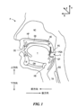
2. Exemplary Stimulation Targets Exemplary embodiments described herein are configured to direct one or more electrical currents to one or more specific target placement locations, e.g., specific nerves and/or specific locations along nerves. A signal emitting device having electrodes that may be positioned is included. Figure 1 shows the general anatomy of a patient's oral cavity, and later figures show specific target locations. Such locations include the patient's hypoglossal nerve, branches of the cervical nerve entrapment, and/or vagus nerve, such as nerves that innervate airway muscles other than the tongue (e.g., palatine, oropharyngeal, and laryngeal muscles). Locations along the lines are listed. Target locations may be identified for any of the following: intrinsic muscles, extrinsic muscles, associated nerve branches, and/or other physiological features, or any combination thereof. Such target locations and/or locations may also be far away from salivary glands (e.g., located inside the sublingual salivary gland) and/or other structures in order to avoid causing pain and/or other undesirable effects. Good location.
図1は、x軸が前方向‐後方向の方向を示し、y軸が上方向‐下方向の方向を示し、z軸が内側‐外側の方向を示す座標系に対して患者Pを示している。患者Pは、舌Tの上に位置していて、口腔OC(例えば、口)のルーフを形成する硬口蓋HPを有する。硬口蓋HPは、骨支持体BS有し、かくして、通常、呼吸中に変形しない。軟組織、例えば、膜、線維質、脂肪組織、筋組織で作られている軟口蓋SPは、硬口蓋HPから咽頭PHRの奥に向かって後方(例えば、後方向)に延びている。より具体的には、軟口蓋SPの前端AEは、硬口蓋HPの後端に固定され、軟口蓋SPの後端PEは、非固定である。軟口蓋SPは、骨又は硬い軟骨を含んでいないので、軟口蓋SPは、撓むことができ、そして咽頭PHRの奥に虚脱すると共に/或いは前後にバタつく場合がある(例えば、特に睡眠中)。 Figure 1 shows a patient P relative to a coordinate system in which the x-axis indicates the anterior-posterior direction, the y-axis indicates the superior-inferior direction, and the z-axis indicates the medial-lateral direction. There is. Patient P has a hard palate HP that lies above the tongue T and forms the roof of the oral cavity OC (eg, mouth). The hard palate HP has a bony support BS and thus does not normally deform during breathing. The soft palate SP, which is made of soft tissues such as membranes, fibrous tissue, adipose tissue, and muscle tissue, extends from the hard palate HP toward the back of the pharynx PHR (for example, in the posterior direction). More specifically, the front end AE of the soft palate SP is fixed to the rear end of the hard palate HP, and the rear end PE of the soft palate SP is not fixed. Because the soft palate SP does not contain bone or hard cartilage, the soft palate SP can flex and collapse into the depths of the pharyngeal PHR and/or may flap back and forth (eg, especially during sleep).
咽頭PHRは、口腔OC及び鼻腔NCから気管TRに空気を送るもので、鼻腔の下(下方)、口腔OCの後方(背後)、かつ食道ESの上方(上)に位置する喉の一部である。咽頭PHRは、両側を舌Tの付け根に向けて下方に延びる、口蓋舌弓PGAによって口腔OCから分離されている。簡略化のために図示していないが、咽頭PHRは鼻咽頭、中咽頭、及び咽喉頭を含んでいる。鼻咽頭は軟口蓋SPの上面と喉の壁(すなわち、口腔OCの上方)との間に位置している。中咽頭は口腔OC背後に位置し、口蓋垂Uから舌骨HBの高さに延びている。中咽頭は前方に向けて口腔OCに開放している。中咽頭の横壁は口蓋扁桃から成り、口蓋舌弓PGAと口蓋咽頭弓との間に位置している。中咽頭の前壁は舌Tの付け根及び喉頭蓋谷から成っている。食物と空気の両方が咽頭PHRを通過するため、食物が飲み込まれたとき、喉頭蓋EPと呼ばれる結合組織の蓋が声門(簡略化のために図示せず)を覆って誤嚥を防止する。咽喉頭は食道ESにつながる喉の一部であり、喉頭蓋EPの下方に位置している。舌Tの下には、下の顎すなわち下顎M及びオトガイ舌骨筋GHが存在し、オトガイ舌骨筋は、舌Tの動きを制御する筋のうちの1つである。 Pharynx PHR sends air from the oral cavity OC and nasal cavity NC to the trachea TR, and is a part of the throat located below (lower) the nasal cavity, behind (behind) the oral cavity OC, and above (above) the esophagus ES. be. The pharyngeal PHR is separated from the oral cavity OC by the palatoglossal arch PGA, which extends downwardly toward the base of the tongue T on each side. Although not shown for simplicity, the pharyngeal PHR includes the nasopharynx, oropharynx, and laryngopharynx. The nasopharynx is located between the upper surface of the soft palate SP and the wall of the throat (ie, above the oral cavity OC). The oropharynx is located behind the oral cavity OC and extends from the uvula U to the level of the hyoid bone HB. The oropharynx opens anteriorly into the oral cavity OC. The lateral wall of the oropharynx consists of the palatine tonsils, located between the palatine arches PGA and the velopharyngeal arches. The anterior wall of the oropharynx consists of the base of the tongue T and the epiglottic vallecula. Because both food and air pass through the pharynx PHR, when food is swallowed, a connective tissue cap called the epiglottis EP covers the glottis (not shown for simplicity) to prevent aspiration. The laryngopharynx is a part of the throat that connects to the esophagus ES and is located below the epiglottis EP. Under the tongue T, there are a lower jaw, that is, a mandible M, and a geniohyoid muscle GH, and the geniohyoid muscle is one of the muscles that control the movement of the tongue T.
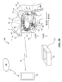
図2Aは、下顎Mに向かって上方に見た患者の頭蓋の部分概略等角図である。図2Aはまた、患者の舌T(図1)を制御する筋を神経支配する舌下神経HGNを示している。代表的な実施形態では、1つ以上の電極131が、内側枝によって定められた電極平面132内において舌下神経HGNに沿って、特に、HGNの内側枝のところに位置決めされている。電極131をこの平面132内に、かつ舌下神経HGNに隣接して正確に位置決めすることによって、本技術の実施形態に係るシステムは、不快感、及び/又は他の望ましくない効果を生じさせることなく、かつ/或いは効果的な治療信号を生じさせるのに必要な電力量を減少させる仕方で患者の気道開存性を一層効果的に制御することができる。本明細書におけるどこか他の場所で説明するように、他の代表的なターゲット神経としては、頸神経ワナ及び迷走神経が挙げられる。さらに別の代表的なターゲットとしては、脳神経(例えば、舌咽神経)及び口蓋舌筋が挙げられる。図2Bは、これらのターゲットを示している。上記ターゲットに方向づけられた信号により、上記及び/又は他の結果をもたらす代表的なシステムについて、図3~図8Bを参照して以下にさらに説明する。
FIG. 2A is a partial schematic isometric view of the patient's skull looking upward toward the mandible M. FIG. FIG. 2A also shows the hypoglossal nerve HGN, which innervates the muscles that control the patient's tongue T (FIG. 1). In an exemplary embodiment, one or
3.代表的な器具及び方法
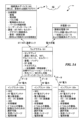
図3Aは、本技術の実施形態に従って睡眠障害を治療するためのシステム100の構成要素を示すブロック図である。システム100は、ウェアラブル器具101(以下、「ウェアラブル」という場合がある)、充電器121、1つ以上のインプラント又は植え込み型器具(例えば、第1の植え込み型器具120a、第2の植え込み型器具120b……n番目の植え込み型器具120n(これらをまとめて「植え込み型器具120」と言う)、及び接続済みデバイス又はプログラマ160を含むのがよい。一般に、プログラマ160は、電気信号(例えば、信号送出又は波形パラメータ)を発生させる命令をウェアラブル器具101に伝送することができ、ウェアラブル器具101は、命令及び電力を植え込み型器具120に伝送することができ、個々の植え込み型器具120は、伝送した命令に従って電気信号を発生させてこの電気信号を植え込み型器具120によって担持された電極を介して患者に印加することができる。システム100の上述の観点のうちの多くについても図3Bを参照して以下に詳細に説明する。
3. Representative Apparatus and Methods FIG. 3A is a block diagram illustrating components of a
プログラマ160は、患者操作式プログラマ及び/又は医師操作式プログラマを含むのがよく、かかるプログラマは、患者に送出される電気信号の1つ以上の特性を制御するよう構成されているのがよい。代表的な実施形態では、プログラマ160は、植え込み型器具120によって担持された個々の電極を選択し、振幅、周波数、パルス幅、バースト継続時間(電極がアクティブ状態であれ非アクティブ状態であれいずれにせよ)及び/又は任意他の適当な信号送出パラメータを調節(例えば、増減)するよう構成された治療調節モジュールを含むのがよい。加うるに、プログラマ160は、個々のウェアラブル101及び/又は植え込み型器具120から受け取った情報(例えば、診断及び/又はフィードバック情報)を同期させるのがよく、そして少なくとも部分的に同期情報に基づいて、信号送出パラメータのうちの1つ以上を調節するのがよい。プログラマ160は、信号送出パラメータを植え込み型器具120に直接的にかつ/或いはウェアラブル器具101を介して伝送するのがよい。例えば、プログラマ160は、個々の植え込み型器具120及び/又はウェアラブル器具101にワイヤード又はワイヤレス通信リンク、例えばWi‐Fi、ブルートゥース(登録商標)(Bluetooth:BT)、セルラー接続、及び/又は任意の他の適当な通信リンクにより接続されるのがよい。これらの実施形態及び他の実施形態では、プログラマ160は、例えば、ウェアラブル器具の101のセンサから受け取ったデータをアップロードすると共に/或いはウェアラブル器具101及び/又は植え込み型器具120に情報をダウンロードするよう、クラウド162及び/又は他のコンピュータサービスに接続されるのがよい。これらの実施形態及び他の実施形態では、プログラマ160は、ディスプレイ及び/又はユーザーインターフェースを含むのがよい。ユーザ(例えば、患者、医師、及び/又は他の適当なユーザ)は、プログラマ160の1つ以上の観点と例えばユーザーインターフェースを介して相互作用すると共に/或いは違ったやり方で制御し、それにより、信号送出パラメータのうちの1つ以上を手動で調節し、ウェアラブル器具101のセンサから受け取ったデータを読み取り、かつ/或いは他のタスクを実行することができる。
ウェアラブル器具101は、患者に関連するデータを収集するよう構成されている1つ以上のセンサ(例えば、単一センサ、センサのアレイ、及び/又は他の適当なセンサ配置)を有するのがよい。ウェアラブル器具は、電源(例えば、電力貯蔵装置及び/又はバッテリ)、電力及び/又は信号送出パラメータを植え込み型器具120に伝送するよう構成された送電コンポーネント、及びウェアラブル器具101の動作の1つ以上の観点を制御するよう構成された1つ以上のアルゴリズムをさらに有するのがよい。個々のセンサは、患者に関連するデータ、例えば、患者の睡眠状態及び/又は呼吸性能を収集するのがよい。1つ以上のアルゴリズムは、少なくとも部分的に、センサによって収集されたデータに基づいて、信号送出パラメータのうちの少なくとも1つを調節するよう構成されているのがよい。代表的な実施形態では、ウェアラブル101は、収集した睡眠状態及び/又は呼吸性能データに基づいて、例えば、1つ以上のアルゴリズムを介して患者に送出された電気信号の1つ以上の送出パラメータを調節し又は違ったやり方で制御するよう構成されている統合睡眠、呼吸診断、及び/又は治療モジュレーション(状態調節)システムを有するのがよい。
幾つかの実施形態では、ウェアラブル器具101は、カバー又はハウジングをさらに有するのがよく、その少なくとも一部分は、ウェアラブル器具101の内部又はその一部分を露出させるよう取り外し可能であるのがよい。この実施形態及び他の実施形態では、ウェアラブル器具101のカバーは、織物、又は任意の他の適当な材料を含むことができる。オプションとして、ウェアラブル器具101は、ユーザがウェアラブル器具101の構成要素のうちの1つ以上と相互作用し、かつ/或いは違ったやり方でこれを制御する(例えば、電源の充電状態をチェックし、信号送出パラメータのうちの1つ以上を調節するなど)ことができるようにするよう構成された縮小されると共に/或いは単純化されたユーザーインターフェースを有するのがよい。
In some embodiments,
ウェアラブル器具101用の充電器121は、電力をウェアラブル器具101の電源に供給するよう構成されているのがよい。充電器121は、ワイヤレス(例えば、インダクティブ)充電器、ワイヤード充電器(例えば、壁プラグ、充電ケーブルなど)、及び/又は任意の他の適当な充電器もしくは充電装置を含むことができる。オプションとして、充電器121は、ウェアラブル器具101の充電を制御すると共に/或いはウェアラブル器具101の充電中にウェアラブル器具101にデータをアップロード/ダウンロード行うための例えば統合コントローラ及び/又は接続デバイスを有するのがよい。
1つ以上の植え込み型器具120の各々は、RFID(例えば、関連植え込み型器具120a~120nを識別すると共に/或いは存在場所を特定するために使用できる一義的なRFIDタグ)、電極受信機アンテナ(例えば、RF電力アンテナ)、電力整流器(順方向変換装置)/DC‐DC変換器、回路部(例えば、1つ以上の特定用途向け集積回路(ASIC)、状態機械など)、信号発生器、及び各々が患者に電気信号を送るよう個々に選択可能である2つ以上の電極を有するのがよい。電極受信機アンテナは、ウェアラブル器具の送電部品から電力を受け取ることができる。電力整流器/DC‐DC変換器は、電極受信機アンテナに動作可能に結合されるのがよく、また、受け取った電力を信号発生器に伝送するよう構成されているのがよい。加うるに、植え込み型器具120の各々は、電極受信機アンテナを介して、信号発生器によって発生されると共に/或いは植え込み型器具120の電極のうちの少なくとも1つを経て患者に送り出されるべき電気信号の送出パラメータのうちの1つ以上に関する情報を受け取ることができる。回路部は、植え込み型器具120の動作と関連した機械可読命令を含むのがよい。例えば、回路部は、実行時に、信号発生器が電極受信機アンテナを経て受け取った信号送出パラメータを有する電気信号を発生させるようにすることができる命令を含むのがよい。これらの実施形態及び他の実施形態では、電極受信機アンテナは、植え込み型器具120と関連した情報をウェアラブル器具101に伝送するよう使用されるのがよい。例えば、植え込み型器具120は、患者に印加される電気信号の信号送出パラメータのうちの1つ以上と関連した情報を電極受信機アンテナ経由でウェアラブル器具101に伝送することができる。これらの実施形態及び他の実施形態では、1つ以上の植え込み型器具120は各々、植え込み型器具120を患者の体内に植え込むことができるよう構成された気密パッケージ又はハウジングを有するのがよい。
Each of the one or more
図3Bは、図1を参照して上述した図と同様な視点において、患者の解剖学的構造との関連で示している図3Aのシステム100の代表的な具体化例の部分概略等角図である。代表的な実施形態では、システム100は、植え込まれた構成要素と外部の構成要素の両方を含む。植え込まれた構成要素は、1つ以上の植え込み型器具120を含むのがよい。各植え込み型器具120は、ターゲット神経及び/又は筋構造に隣接して位置決めされた信号送出装置130を有するのがよい。信号送出装置130は、縫合糸及び/又は他の器具、例えばアンカーにより定位置に固定されるのがよい。信号送出装置130は、信号発生器110に動作可能に結合されている。幾つかの実施形態では、信号発生機能は全て、植え込み型器具120によって実行され、他の実施形態では、幾つかの信号発生機能は、外部構成要素によって実行可能である。信号発生機能及び信号送出機能は、単一の植え込み型器具120によって実行されてもよく、多数の器具によって実行されてもよい。
FIG. 3B is a partial schematic isometric view of a representative implementation of the
ウェアラブル器具101は、電源109を担持するのがよい。説明の目的上、ウェアラブル器具101は、口内器具123、例えばマウスピースを含むものとして図3Bに示されており、この口内器具は、電源109を担持している。上述したように、ウェアラブル器具101は、他の実施形態では、他の適当な構成(例えば、カラー、あご紐、ピロー、マットレスオーバーレイ)を有することができる。電源109は、電力を信号発生器110に提供し、信号発生器は、信号(例えば、治療信号)を発生させて、これら信号を信号送出器具130によって担持された1つ以上の電極131に方向づける。信号送出装置130は、低侵襲法を用いて、例えば、経皮注射針を用いて、患者の舌下神経HGNのところに又はこの近くに植え込まれるのがよい。電源109は、電力をワイヤレス送電リンク114、例えば、ミッドフィールドRF送信リンク経由で信号発生器110に提供する。
信号発生器110は、代表的には、ウェアラブル器具101によって制御され、ウェアラブル器具101は、プログラマ160及び/又は任意の他の適当なデバイスによってワイヤレスプログラマリンク161経由で制御されるのがよい。したがって、患者P及び/又は医師は、プログラマ160を用いて信号発生器110を方向づけ(ウェアラブル器具101により)、それにより特定の信号を特定の時間にかつ/或いは特定の順序に従って特定の電極に送ることができる。プログラマリンク161は、双方向リンクであるのがよく、その結果、プログラマ160(ウェアラブル器具101及び/又は信号発生器110への命令の提供に加えて)は、治療、システムコンポーネントの状態、及び/又は他の適当なメトリックスに関するデータを受け取ることができる。データは、ウェアラブル器具101(概略的に図3Bに示されているように)及び/又は植え込み型器具120によって担持された1つ以上のセンサ119によって収集されるのがよい。加うるに、プログラマ160は、クラウド162及び/又は他のコンピュータサービスと通信して、患者Pから受け取ったデータをアップロードすると共に/或いはウェアラブル器具101及び/又は植え込み型器具120に情報をダウンロードすることができる。ダウンロードされたデータは、適当な治療(例えば、他の同様な状況にある患者から)に関する命令及び/又は他のデータ、ウェアラブル器具101及び/又は植え込み型器具120によって担持された回路上で実行されるソフトウェアについてのアップデート、及び/又は他の有用な情報を含むのがよい。他の実施形態では、植え込み型器具120及び/又はウェアラブル器具101は、アップデート可能ではない状態機械コンポーネントを含む。患者から受け取る代表的なデータは、とりわけ、呼吸数、睡眠状態、覚醒状態、心拍数、音声信号(可聴いびき、低呼吸イベント、及び/又は無呼吸イベント)、体温、頭部の向き/位置、飽和血液酸素レベル、空気流量レベル、甲状腺の動き、気管の動き、及び/又は舌の動き、光電式容積脈波記録法(photoplethysmography:PPG)データを含むのがよい。患者から受け取ったデータは、ウェアラブル器具101及び/又は植え込み型器具120によって担持された119によって生成されるのがよい。代表的な実施形態では、ウェアラブル器具101は、実行機能、例えば、患者に提供される治療を開始し調節すると共に/或いは停止させるためにプログラマ160及び/又はセンサ119から受け取った情報の同期を実行する。したがって、ウェアラブル器具によって担持された回路部は、センサから受け取った情報に基づいて、植え込み型器具に送られた治療を開始させ、変更し、かつ/或いは停止するための命令がプログラムされたコントローラを含むのがよい。受け取ったデータは、患者の呼吸性能、睡眠状態、覚醒状態、及び/又は他の適当なメトリクス、例えば、無呼吸低呼吸指数(AHI)についてレーティングするために用いられるメトリックスの尺度に対応するのがよい。
上述の実施形態のうちの任意のものにおいて、ウェアラブル器具101は、電力を1つ以上の送電リンク112経由で植え込み型器具120に伝送したり、電力を(例えば、断続方式で)充電器121から受け取ったりする。充電器121は、上述すると共に図3Aを参照して、したがって、従来型誘導結合装置(例えば、Qi規格充電)及び/又は従来型ワイヤード接続方式を採用するのがよい。
In any of the embodiments described above,
快適な装用のため、ウェアラブル器具101(口内器具123であれ他形式のウェアラブルであれいずれにせよ)は、患者にカスタムフィットさせることができ、又は種々のサイズで利用可能に作られているのがよく、かつ/或いは個々の患者に合うように部分的に構成可能であるのがよい。口内器具123は、関連する信号送出器具130が、口腔内のターゲット神経集団(例えば、HGN)のところに又はこれらの近くに位置決めされたときに最適である。ウェアラブル器具がマウスピースの形状因子を有するにせよ別の適当な形状因子を有するにせよいずれにせよ、ウェアラブル器具がHGN以外のかつ/或いはこれに加えて神経集団、例えば、迷走神経及び/又は頚神経ワナの枝をターゲットにするために用いられる場合であっても、電力を植え込み型器具120に提供することができる。さらに別の実施形態では、電源109は、接着剤により患者の皮膚に取り付けることができるが、接着剤を避けることが患者にとってより望ましく/効果的であることが予想される。
For comfortable wear, the wearable appliance 101 (whether an
図3Bに示す特定の実施形態を参照すると、口内器具123は、上マウスピース部分111と下マウスピース部分112の両方を有するのがよい。2つのマウスピース部分111,112は、コネクタ113により互いに結合されるのがよい。コネクタ113は、2つのマウスピース部分相互間にワイヤード通信リンクをもたらすことができ、かつ/或いはコネクタ113は、下マウスピース部分112を上マウスピース部分111に対して機械的に位置決めすることができる(かつ/或いはその位置を維持し又は安定化することができる)。このやり方を用いると、例えば、患者の下の顎又は下顎Mを、図3Bの骨構造BSによって指示されている患者の上顎に対して前進させることができる。例えば、本技術の諸実施形態は、ウェアラブル器具によって電力供給される電気刺激に加えて、ウェアラブル器具101の物理的要素を用いて、顎弛緩(患者の口がぽかんと開いた状態)を避け又は少なくとも軽減する。例えば、カラー及び/又はあご紐を備えたウェアラブル器具は、患者の顎をターゲット位置に機械的に安定化することができる。
Referring to the particular embodiment shown in FIG. 3B,
電源109は、充電器121から電力を受け取り、そして電力を信号植え込み型器具120に伝送可能に蓄える1つ以上の電荷貯蔵装置116(例えば、1つ以上のバッテリ)を含むのがよい。したがって、電源109は、電荷貯蔵装置116から電力を受け取り、この電力を調整し、そしてこの電力を送電アンテナ118に伝送する回路部115(例えば、第1の回路部)を有するのがよい。送電アンテナ118は、電力をワイヤレス送電リンク114及び信号送出装置130によって担持された電極受信機アンテナ133経由で植え込み型器具120に伝送する。
口内器具123は、プログラマ160からデータを受け取ると共に/或いはプログラマ160にデータを伝送するデータ送受信アンテナ117をさらに有するのがよい。プログラマ160に伝送されるデータは、1つ以上のセンサ119から得られたセンサデータを含むのがよい。したがって、口内器具123は、電力を信号送出装置130に方向づけるのに必要な機能要素/コンポーネントを担持するのがよく、また、患者にとって効果的な治療を提供するようプログラマ160と通信するのがよい。信号送出装置130及び信号発生器110についてのさらなる詳細について図4~図8Bを参照して以下に説明する。
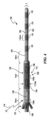
図4は、本技術の代表的な実施形態に従って構成された構成要素を有する信号送出装置130の部分概略側面図である。スケール感を提供するために代表的な寸法が図4に示されているが、本技術は、明示の指定がない場合にこれらの寸法によって制限されることはない。信号送出装置130は、全体として可撓性であるのがよくかつ1つ以上の電極131を担持することができるリード本体134を有し、1つ以上の電極131は、幾つかの実施形態では、全体として剛性であり、他の実施形態では、可撓性であるのがよい。可撓性電極は、ターゲット神経の近くの曲がりくねった解剖学的構造/挿入経路に対応するようリード本体全体の可撓性を増大させる。説明の目的上、リード本体134は、図4において4つの電極131を担持するものとして示されているが、他の実施形態では、リード本体134は、他の適当な数の電極、例えば2つの電極131を担持することができる。電極131は、アレイをなして、例えば一次元直線アレイをなして配列されるのがよい。電極131は、適当な生体適合性材料、例えば、白金/イリジウム、ステンレス鋼、MP35N及び/又は他の適当な導電性インプラント材料で作られた従来型リング形状又は円筒形の電極を含むのがよい。電極131は各々、リード本体134を貫通した個々の導体140、例えば、細いワイヤフィラメントに連結されるのがよい。各電極131は、図4に示すようにおよそ1.5mmの長さを有するのがよく、又は他の実施形態では別の適当な長さを有することができる。閉回路を構成するため、電極131は、代表的には、一対ずつ(少なくとも一対ずつ)互いに接続されるのがよい。ハウジング135及び/又はハウジング135の幾つかの部分は、電極として、例えば接地電極又は戻り電極として働くのがよい。
FIG. 4 is a partial schematic side view of a
リード本体134は、ハウジング135に接続されると共にこれによって担持され、ハウジング135は、信号発生器110及び電力を受け取るための回路素子を担持している。例えば、ハウジング135全体は、アンテナハウジング又はハウジング部分135a及び回路ハウジング又は回路ハウジング部分135bを有するのがよい。アンテナハウジング135aは、可撓性であるのがよく、このアンテナハウジングは、ウェアラブル器具101(図3A及び図3B)からワイヤレス送電リンク114を介して電力を受け取る受信機アンテナ133(他の適当な電力受け取り装置)を担持するのがよい。回路ハウジング135bは、チタン及び/又は別の適当な材料で作られた全体として円形の金属「缶」の形態をしているのがよい。信号発生器110は、受信機アンテナ133に結合されたチャージポンプ及び/又はDC‐DC変換器139及び/又は回路部138(例えば、第2の回路部)を有するのがよい。回路部138は、対応の機械可読命令を含むのがよいASICを有するのがよい。命令は、電力伝送に加えてデータ伝送のために電極受信機アンテナ133を用いて、ワイヤレスでアップデートされるのがよい。例えば、データは、パルス幅変調(PWM)及び/又は他の適当な技術を用いて伝送されるのがよい。データはまた、例えば後方散乱及び/又は他の適当な技術を用いて逆方向に伝送可能である。例えば、植え込み型器具120は、電力を受け取ったということ及び電力がどれほどの大きさであるかを指示する受け取りを伝送するのがよい。この情報を用いると、信号発生器110の出力、例えば送信した信号及び相を自己調節する(上下に)ことができる。したがって、回路部138は、治療信号を患者に送出するためにプロセッサ及びメモリを有するのがよく、係るプロセッサ及びメモリとしては、予めプログラムされると共にアップデート可能な命令(例えば、ASICの形態をしている)が挙げられる。例えば、システムは、ブートローダ組み込み型ファームウェアを含むのがよい。さらに、システム全体は、RFID型送電認証法を用いて単一のウェアラブル器具101によって電力供給されるのがよい多数の植え込み型器具を識別することができる。RFID及び/又は他の技術を用いると、異物により又は意図しない刺激が起こることがないようにするようにセキュリティ措置を具体化するのがよい。係る技術は、少なくとも幾つかの実施形態では、植え込み型器具120に実装された適当なハードウエア/ソフトウェアにより具体化できる。
ハウジング部分135全体は、全体として剛性であるベース136及び1つ以上のアンカー137をさらに有するのがよい。アンカー137は、植え込み型器具120を患者の組織に対して確実に位置決めする。代表的な実施形態では、アンカー137は、植え込み型器具120が患者の体内に注入され又は違ったやり方で植え込まれた時に外方にかつ患者の組織中に延びる1つ以上の歯を有する。他の実施形態では、植え込み型器具120は、他の適当なアンカーを有するのがよく、かつ/或いは繋留は、信号送出装置130の遠位区分及び/又は中間区分のところで起こるのがよい。他の適当なアンカーとしては、(a)電極アレイの長手方向長さにわたって延び、そして導入シースが引き抜かれた時に固定摩擦力を生じさせるよう曲がる弓形ばね(bow spring)、(b)ばね押しヒンジに設けられていて、電極アレイの長手方向長さに渡って延び、そして導入シースが引き抜かれた時に固定摩擦力を生じさせるよう撓る細いワイヤ、(c)回転時に拡径してまた対応のプッシュロッドがインプランタによって回されている時に摩擦固定作用を生じさせるカム及び/又は(d)回転時に拡径してまた対応のプッシュロッドがインプランタによって回されている時に摩擦固定作用を生じさせるねじりばね(torsion spring)が挙げられるが、これらには限定されない。
The
植え込み型器具120を植え込むため、医師は、代表的な1組の経皮インプラントツール、例えば導入器、針、カニューレ、及びスタイレットを用いて植え込み型器具120を所望のターゲット場所に位置決めする。特定の実施例では、植え込み型器具120は、3~4フレンチ針で経皮的に植え込まれる。植え込み型器具120をカニューレから前進させているとき、アンカー137は、外方に展開することができ、そして植え込み型器具120を定位置に固定することができる。例えばスタイレットをハウジング部分135のベース136及び/又は他の部分に設けられている孔から軸方向に引き抜くことによってスタイレットを植え込み型器具120から抜去したとき、植え込み型器具120は電力を受け取り、そして治療信号をターゲット神経に送出することができる状態にある。
To implant
作用を説明すると、受信アンテナ133は、関連のウェアラブル器具101(図3A及び図3B、そして図5A~図6を参照して以下にさらに詳細に説明する)によって担持された電源109からワイヤレスで電力を受け取る。少なくとも幾つかの実施形態では、受信機アンテナ133のところで受け取られた電力は、ミッドフィールド(midfield)範囲内にあり、例えば、約300MHzから約6GHzまでの範囲、例えば約600MHzから約2.45GHzまでの範囲、又は約900MHzから約1.2GHzまでの範囲にある無線周波数の状態にある。この周波数では、ワイヤレス送電リンク114の使用可能な範囲は、植え込み型器具120とウェアラブル器具101との間の距離に及ぶのに足るほどの距離を優に超えて約10cmである。この範囲では、送電プロセスは、組織加熱を生じさせるものとは見込まれず、したがって、他の送電技術、例えば誘導型送電技術と比較して利点をもたらす。しかしながら、誘導型送電方式により生じる潜在的な加熱を適度に制御する実施形態では、誘電技術は、本明細書にて説明するミッドフィールド送電技術に代えて使用できる。
In operation, the receiving
受信機アンテナ133のところで受け取ったAC電力を整流してDCにし、次にDC‐DC変換器、チャージポンプ及び/又は変圧器139に伝送し、そして約10Hzから約300Hzまでの範囲にあるパルスに変換する。他の実施形態では、パルスを高い周波数(例えば、10kHz以上)でかつ/或いはバーストの形態で送出するのがよい。信号の振幅は、電圧制御系では約1mV~約5V(特定の実施形態では、1V~2V)であるのがよく、或いは電流制御系では約1mA~約6mAであるのがよい。回路部138は、これら信号送出パラメータを制御し、そして結果として生じる電気信号をリード本体134内のワイヤフィラメント又は他の導体140経由で電極131に伝送する。したがって、回路部は、これが植え込み型器具120にワイヤレスで伝送された電力を受け取り、そして最終的には患者に送出される信号を発生させるという点で信号発生器110を形成する(少なくとも一部を形成する)。電流が電極131によって流された結果として生じる電界は、ターゲット神経のところで所望の効果(例えば、励起及び/又は抑制)を生じさせる。少なくとも幾つかの実施形態では、植え込み型器具120は、システムボリュームを減少させるために搭載型電力貯蔵素子(例えば、電力キャパシタ及び/又はバッテリ)を何ら備える必要がなく又は0.5秒超の貯蔵能力を備えた電力貯蔵要素を何ら備える必要がない。他の実施形態では、植え込み型器具120は、植え込み型器具120の全体的にコンパクトな形状と適合性がありかつ実施形態に応じて、1秒以下、30秒以下、1分以下、2分以下、又は5分以下の全電荷貯蔵能力を有する1つ以上の小型電荷貯蔵装置(例えば、キャパシタ)を有するのがよい。
AC power received at
少なくとも幾つかの実施形態では、患者に送出された電気信号を電極131のうちの2つによって形成されるバイポールにより送出するのがよい。他の実施形態では、信号は、単極信号であるのがよく、ハウジング135(例えば、回路ハウジング部分135b)は、接地電極又は戻り電極を形成する。一般に、波形は、図8A及び図8Bを参照して以下に詳細に説明するように、二相性、電荷平衡波形を含む。
In at least some embodiments, the electrical signals delivered to the patient may be delivered by a bipole formed by two of the
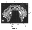
図5A~図6は、本発明の代表的な実施形態にしたがって、電力を植え込み型器具120に供給するよう構成されたウェアラブル器具101を示している。最初に図5Aを参照すると、代表的なウェアラブル器具101が上マウスピース部分111及び下マウスピース部分112を備えた口内器具123を含む。下マウスピース部分112は、図4を参照して上述したように、電力を植え込み型器具120に方向づける1つ以上の送電アンテナ118を有する。代表的な実施形態では、患者は、両側に、すなわち、患者の2つの舌下神経の各々のところに植え込まれた2つの植え込み型器具120を着用しており、一方の植え込み型器具が患者の口腔の右側上に配置され、他方の植え込み型器具が左側上に配置されている。したがって、口内器具123は、各々が電力を植え込み型器具120の各々にそれぞれ方向づけるよう位置決めされた2つの送電アンテナ118を有するのがよい。図5Aに示す実施形態では、下マウスピース部分112は、左延長部124a及び右延長部124bとして示されている2つの対応の延長部124を有する。各延長部124は、送電アンテナ118の各々をそれぞれ収容し、各延長部は、患者が口内器具123を着用した時に、患者にとって快適なままである仕方で対応の植え込み型器具120の近くに送電アンテナ118を配置するよう位置決めされている。
5A-6 illustrate
口内器具123は、回路部115に結合された1つ以上の電源116をさらに有し、回路115は、電力を送電アンテナ118に方向づける。電源116は、信号伝送装置を適当な治療期間の間、供電するのに十分なエネルギーを蓄えるよう構成された1つ以上のバッテリ、キャパシタ、及び/又は他の電荷貯蔵装置を含むのがよい。適当な治療期間としては、代表的には、幾つかの実施形態では少なくとも4時間、他の実施形態では少なくとも一晩が挙げられる。回路部115は、電流を電源116から受け取ってこの電流を適当なミッドフィールド高周波に変換する。電流は、送電アンテナ118に方向づけられる。図5Aに示す実施形態では、回路部115及び電源116は、下マウスピース部分112によって担持され、係る回路部及び電源は、患者の下唇の方へ向くよう下マウスピース部分112の外面に沿って位置決めされる。この構成では、電気素子は、患者の舌の前運動を妨害することが見込まれていない。もう1つの実施形態では、例えば、図5Bに示すように、回路部115及び電源116は、上マウスピース部分111によって担持されるのがよい。この実施形態では、回路部115及び電源116は、患者の唇の方ではなく、患者の口腔の内部の方へ向くよう上マウスピース部分111の内面に沿って位置決めされる。電気素子が上マウスピース部分111上に位置するので、これら電気素子は、これらが患者の口腔の内部の方へ向く場合であっても、患者の舌の前運動を妨害しないことが見込まれる。回路部115は、上マウスピース部分111と下マウスピース部分112との間に結合されたコネクタ113(図3Bに示す)を対応関係を成して通る1本以上のワイヤ(図5Aには示されていない)により電流をアンテナに方向づける。
図5Cは、ウェアラブル器具101が上マウスピース部分111によって担持された回路部115及び下マウスピース部分112によって担持された電源116を有する別の代表的な実施形態を示している。この場合、コネクタ113(図3B)によって担持された通信リンクが電源116からの電流を回路部115に流し、次に電流を回路部115から送電アンテナ118(図5Cでは見えない)に流す。
FIG. 5C shows another exemplary embodiment in which
図6は、本技術のさらに別の実施形態にしたがって構成されたウェアラブル器具601の部分概略等角図である。上マウスピース部分111は、患者の口蓋に当てて上方に位置決めされるよう上マウスピース部分111の一方の側部から他方の側部に横方向に延びるルーフ部分622を有する。したがって、ウェアラブル器具101の構成要素のうちのいくつかは、ルーフ部分622によって担持されるのがよい。係る構成要素としては、回路部115、電源116、データ送受信アンテナ117(図3Bを参照して上述した)、充電コイル621(電源116を図3A及び図3Bに示す充電器121により再充電する)、及び1つ以上のセンサ119(これまた図3A及び図3Bを参照して上述した)が挙げられる。したがって、ルーフ部分622は、ウェアラブル器具101の上述の構成要素を収納担持する追加の容積部となることができる。センサ119としては、例えば、温度センサ、例えばサーミスタ及び/又は熱電対、音響センサ、振動センサ、圧力センサ、力センサ、ひずみ計、磁力計、加速度計、ジャイロスコープ、インピーダンスセンサ、EMGセンサ、ガスセンサ、及び/又は化学センサ、酸素飽和センサ、光電脈波センサ、流動センサ(口マノメトリ又は鼻マノメトリ)、及び/又は患者の状態又は特性(例えば、睡眠状態、覚醒状態)を検出することができる他のセンサが挙げられるが、これらには限定されない。幾つかの代表的な実施形態では、患者の呼吸パラメータを用いると、患者の呼吸サイクル並びに無呼吸イベントが起きている又は起きようとしていることを指示することができる情報に基づいて、刺激をトリガすることができる。特定の実施形態では、全体的システムは、パルスオキシメータ、光電脈波センサ、及びシステム行為の基礎となるべき適当な患者フィードバックを提供するための少なくとも1つの患者定位センサを含む。
FIG. 6 is a partial schematic isometric view of a
図5A~図6を参照して説明した上述のコンポーネントのうちの任意のものをマウスピース部分の外面に沿って配置することができ又は他の実施形態では、これらコンポーネントは、マウスピース部分から外方ではなく内方に向いてもよい。上述したように、マウスピースの外面上に位置するコンポーネントの利点は、舌が刺激中に前へ突き出ている時に舌によって占められた空間にコンポーネントが当たらないということにある。少なくとも幾つかの実施形態では、バッテリは、これを容易に取り外したり交換したりすることができるよう位置決めされるのがよい。 Any of the components described above with reference to FIGS. 5A-6 may be disposed along the exterior surface of the mouthpiece portion, or in other embodiments, these components may be externally disposed from the mouthpiece portion. You can also face inward instead of inward. As mentioned above, the advantage of a component located on the outer surface of the mouthpiece is that it does not impinge on the space occupied by the tongue when it is protruding forward during stimulation. In at least some embodiments, the battery may be positioned such that it can be easily removed and replaced.
図7は、本技術の代表的な実施形態にしたがって患者に印加された電気信号を制御する装置の略図である。一般的に、制御回路部115は、電流を1つ以上の送電アンテナ118に提供し、送電アンテナ118は、電力を対応のワイヤレス送電リンク114経由で対応の電極受信機アンテナ133に方向づける。
FIG. 7 is a schematic diagram of an apparatus for controlling electrical signals applied to a patient in accordance with an exemplary embodiment of the present technology. Generally,
説明の目的上、図7は、単一器具に設けられた2つの制御構成例を示しており、1つの構成例は、患者の口腔の左側のためであり、もう1つの構成例は、右側のためのものである。これは、1つの考えられる構成であり、他の実施形態では、同一の構成例は、左側と右側の両方に用いられる。図7に示すように、第1の受信機アンテナ133aは、信号を4つの対応の電極131の各々に提供することができる。2つの第2の受信機アンテナ133bは、各々、電力を2つの電極131に提供することができる。具体化された構成例は、対応の受信機アンテナにより個々の電極の制御と関連した有用性に基づいて選択されるのがよい。例えば、第1の受信機アンテナ133aは、同一の信号をこれに接続された多数の電極131(及び/又は電極131の対)に同時に送り出すことができる。他方、第2の受信機アンテナ133bは、各々、これらに結合された対応の電極に信号を別個独立に送り出すことができる。これにより、第2の受信機アンテナ133bは、対応の電極131に印加される信号を順序付けることができる。幾つかの実施形態では、この構成例により、有利には、医師が1つの信号を一時点で舌下神経の1つの部分に方向づけることができ、同一又は別の信号を舌下神経のもう1つの部分又はもう1つの神経に別の時点で方向づけることができる。予期されるように、1つ又は複数のターゲット神経に送り出される信号の空間的観点と時間的観点の両方を制御することができるということにより、器具が患者の閉塞性睡眠時無呼吸(OSA)を軽減する効能を向上させることができる。例えば、舌下神経の互いに異なる部分、及び/又は頸神経ワナ(例えば、咽頭の尾方運動を促進するため)及び/又は迷走神経を含む他の神経に、その枝が咽頭及び舌口蓋の運動筋を含む上気道の多くの筋を活動させているときに、信号を送出するのがよい。
For purposes of illustration, FIG. 7 shows two example control configurations on a single appliance, one example configuration for the left side of the patient's oral cavity and another example configuration for the right side of the patient's oral cavity. It is for. This is one possible configuration; in other embodiments, the same example configuration is used for both the left and right sides. As shown in FIG. 7, the
より一般的に言えば、多数の注入可能な電極131は、対応の筋の収縮を順序づけ、それにより患者の睡眠障害に取り組むよう段階的な仕方で(例えば、ミリ秒範囲のタイミングオフセットで)遠隔に位置決めされたウェアラブル器具によって、ワイヤレス活性化されるのがよい。加うるに、システムは、植え込み済みの信号送出装置によって提供される確実性及びロバストネスと組み合わせて信号先が定められたターゲットニューロンを変化させる融通性を持つ。
More generally, a number of
少なくとも幾つかの実施形態では、制御回路部115は、送電アンテナ118の両方を制御し、したがって、患者に送り出される信号の全体的制御を可能にする。他の実施形態では、1つ以上のアンテナ118及び/又は対応の電極131を制御する権限を分散させるのがよい。例えば、制御回路部の一要素は、一方の送電アンテナ118を制御するのがよく、もう1つの構成要素は、他方の送電アンテナ118を制御するのがよい。制御権限を図7に示すように互いに異なる受信機アンテナ133にさらに分散させるのがよい。これら実施形態のうちの任意のものにおいて、制御が高レベル制御回路部115の下に分散させたときシステムは全ての制御構成要素を同期状態に保つよう個々のコントローラ素子相互間の通信を可能にする手段を含む。
In at least some embodiments,
4.代表的な波形
上述した信号発生器及び送出装置は、種々の適当な電気刺激波形のうちの任意のものを発生させると共に送出することができ、それにより患者の神経及び/又は筋の動作を状態調節することができる。代表的な実施形態が、図8A及び図8Bに示されており、これら実施例は、図8A及び図8Bに特定されたような周期を有する刺激波サイクルを形成する一連の二相性刺激パルスを含む。波形パラメータは、活性サイクル及び休息サイクルを含むのがよい。各期間Pは、1つ以上のパルスを含む。図8Aに示す波形は、アノードパルス、次に相間遅延、次にカソードパルス、次にパルス間遅延を含む。したがって、期間P又はサイクル全般は、以下のパラメータ、すなわち、アノードパルス幅(PW1)、アノード振幅(例えば、電圧又は電流振幅VA)、相間遅延/無駄時間、カソードパルス幅(PW2)、カソード振幅(例えば、電圧又は電流振幅VC)、パルス間遅延/空き時間、及びピークピーク振幅(PP)を含む。パラメータは、信号を方向づける電極の同一性表示をさらに含むのがよい。幾つかの実施形態におけるアノードパルス幅(PW1)は、30μs~300μsである。幾つかの実施形態におけるアノード振幅(VA)及びカソード振幅(VC)は、1mVから5Vまでの範囲、又は1mAから6mAまでの範囲にある。代表的な実施形態における相間遅延は、10μs~100μsであるのがよい。幾つかの代表的な実施形態におけるカソードパルス幅(PW1)は、30μs~300μsである。代表的な実施形態では、アノード相及びカソード相は、電荷平衡が取られており、ただし、これらの相は、対称の形をしている必要はない。幾つかの代表的な実施形態におけるパルス間遅延は、10μs~100μsであるのがよい。幾つかの代表的な実施形態におけるピークピーク振幅は、約2mA~12mAであるのがよい。代表的な周波数は、幾つかの実施形態では約10Hzから約300Hzまでの範囲にあり、他の実施形態では最高100kHz(例えば、10kHz)である。これらのパルスを連続的に送り出すことができ又はバースト状態で送り出すことができる。
4. Representative Waveforms The signal generators and delivery devices described above are capable of generating and delivering any of a variety of suitable electrical stimulation waveforms to thereby condition nerve and/or muscle operation in a patient. Can be adjusted. Representative embodiments are shown in FIGS. 8A and 8B, which include a series of biphasic stimulation pulses forming a stimulation wave cycle having a period as specified in FIGS. 8A and 8B. include. The waveform parameters may include active cycles and rest cycles. Each period P includes one or more pulses. The waveform shown in FIG. 8A includes an anode pulse, then an interphase delay, then a cathode pulse, then an interpulse delay. Therefore, the period P or cycle in general depends on the following parameters: anode pulse width (PW1), anode amplitude (e.g. voltage or current amplitude VA), phase-to-phase delay/dead time, cathode pulse width (PW2), cathode amplitude ( Examples include voltage or current amplitude (VC), interpulse delay/idle time, and peak-to-peak amplitude (PP). The parameters may further include an indication of the identity of the electrode directing the signal. The anode pulse width (PW1) in some embodiments is between 30 μs and 300 μs. The anode amplitude (VA) and cathode amplitude (VC) in some embodiments range from 1 mV to 5V, or from 1 mA to 6 mA. The phase-to-phase delay in exemplary embodiments may be between 10 μs and 100 μs. The cathode pulse width (PW1) in some exemplary embodiments is between 30 μs and 300 μs. In exemplary embodiments, the anode and cathode phases are charge balanced, although the phases need not be symmetrically shaped. The interpulse delay in some exemplary embodiments may be between 10 μs and 100 μs. The peak-to-peak amplitude in some exemplary embodiments may be about 2 mA to 12 mA. Typical frequencies range from about 10 Hz to about 300 Hz in some embodiments, and up to 100 kHz (eg, 10 kHz) in other embodiments. These pulses can be delivered continuously or in bursts.
図8Bは、活動部分及び休息部分を含む代表的な波形を示している。活動部分は、図8Aを参照して上述した特性を備える1つ以上の期間を含む。休息部分には、刺激パルスはない。幾つかの代表的な実施形態によれば、活動部分と休息部分の比は、1:1~1:9であるのがよい。代表的な実施例として、比が1:9でありかつ300の活動期間が存在する場合、2700の休息部分が存在するのがよい。 FIG. 8B shows a representative waveform including an active portion and a rest portion. The active portion includes one or more time periods with the characteristics described above with reference to FIG. 8A. During the rest part, there are no stimulation pulses. According to some exemplary embodiments, the ratio of active to rest portions may be between 1:1 and 1:9. As a typical example, if the ratio is 1:9 and there are 300 active periods, there may be 2700 rest periods.
代表的な実施例では、刺激電圧は、各接点又は電極に独立して提供されるのがよい。正のパルスに関し、正の接点を駆動電圧に引き寄せるのがよく、負の接点をアースに引き寄せるのがよい。負のパルスに関し、負の接点を駆動電圧に引き寄せるのがよく、正の接点をアースに引き寄せるのがよい。無駄時間及び空き時間に関し、両方の接点をアースに駆動する。休息時間に関し、両方の接点は、高インピーダンス状態にある。接点中のDC電流を防ぐため、各ハーフブリッジをキャパシタ、例えば、100μFキャパシタにより接点に結合するのがよい。加うるに、抵抗器を各キャパシタと直列に配置して接点短絡の場合に電流を制限するのがよい。治療波形サイクルのパルスは、対称であってもよく、また対称でなくてもよいが、一般に、例えば電荷平衡を提供するために接点を横切る正味ゼロの電荷をもたらすよう形作られている。 In typical embodiments, stimulation voltages may be provided to each contact or electrode independently. For positive pulses, the positive contact may be drawn to the drive voltage and the negative contact may be drawn to ground. For negative pulses, the negative contact may be drawn to the drive voltage and the positive contact may be drawn to ground. For dead time and idle time, both contacts are driven to ground. During the rest period, both contacts are in a high impedance state. To prevent DC currents in the contacts, each half-bridge may be coupled to the contacts by a capacitor, for example a 100 μF capacitor. Additionally, a resistor may be placed in series with each capacitor to limit the current in the event of a contact short circuit. The pulses of the treatment waveform cycle may or may not be symmetrical, but are generally shaped to provide zero net charge across the contacts, eg, to provide charge balance.
上記内容から、本技術の特定の実施形態を例示目的で本明細書において説明したが、本技術から逸脱することなく、種々の改造を行うことができることが理解されよう。例えば、電源及び関連ウェアラブルは、口内マウスピース以外のこれまた電力を1つ以上の植え込み済み電極にワイヤレスで送り出す構成を有することができる。代表的な構成としては、外部皮膚取り付け型デバイスや患者の首回りに着用される器具が挙げられ、これら器具は、頸神経ワナ、迷走神経及び/又はHGN以外の他の神経をターゲットにするのに適している場合がある。刺激のための他の代表的なターゲットとしては、舌口蓋刺激、脳神経刺激、直接舌口蓋筋刺激、鼻咽頭刺激及び/又は舌咽神経刺激が挙げられる。信号送出装置を定位置に固定するために用いられるアンカーは、配備可能な歯以外の形態を有することができ、かかる形態としては、組織内方成長を促進するS字形カーブ素子、螺旋及び/又は多孔性構造を含む。ハウジング全体を形成する多数のハウジングを含む信号送出装置については上述した。他の実施形態では、多数のハウジングは、一体的ハウジング全体の部分であってよい。システム全体により実行される機能を明示的に図示すると共に本明細書において説明したやり方以外のやり方でシステム構成要素(例えば、プログラマ、ウェアラブル器具、及び植え込み型器具)に分割することができる。 From the foregoing, it will be appreciated that while particular embodiments of the technology have been described herein for purposes of illustration, various modifications may be made without departing from the technology. For example, the power source and associated wearable may be configured to wirelessly deliver power to one or more implanted electrodes other than the intraoral mouthpiece. Typical configurations include external skin-mounted devices or devices worn around the patient's neck that target the cervical nerve entrapment, the vagus nerve, and/or other nerves other than the HGN. may be suitable for Other exemplary targets for stimulation include tongue and palate stimulation, cranial nerve stimulation, direct tongue and palate muscle stimulation, nasopharyngeal stimulation, and/or glossopharyngeal nerve stimulation. The anchors used to secure the signal delivery device in place can have forms other than deployable teeth, including S-curve elements, helices, and/or spirals to promote tissue ingrowth. Contains a porous structure. A signal delivery device has been described above that includes multiple housings forming an entire housing. In other embodiments, multiple housings may be part of an overall integral housing. The functions performed by the overall system may be divided into system components (eg, programmer, wearable device, and implantable device) in ways other than those explicitly illustrated and described herein.
特定の実施形態と関連して説明した技術のある特定の観点を他の実施形態によって組み合わせることができ又は省略することができる。例えば、種々の適当な構成のうちの任意のものを有する信号送出装置を任意の1つの信号発生器と併用することができ、種々の適当な構成のうちの任意のものを有する信号発生器を任意の1つの信号送出装置と併用することができる。さらに、開示した技術のある特定の実施形態と関連した利点をこの実施形態と関連して説明したが、本技術の範囲に属する他の実施形態もまた、かかる利点を奏することができ、必ずしも全ての実施形態がかかる利点を奏する必要はない。したがって、本開示及び関連技術は、明示的に図示されていない本明細書において説明されていない他の実施形態を含むことができる。 Certain aspects of the techniques described in connection with particular embodiments may be combined or omitted by other embodiments. For example, a signal emitting device having any of a variety of suitable configurations may be used with any one signal generator, and a signal generator having any of a variety of suitable configurations may be used with any one signal generator. Can be used with any one signaling device. Furthermore, although the advantages associated with a particular embodiment of the disclosed technology have been described in connection with this embodiment, other embodiments within the scope of the present technology may also exhibit such advantages, and not all of the advantages may be provided. It is not necessary for embodiments of the invention to exhibit such advantages. Accordingly, the present disclosure and related technology may include other embodiments not explicitly illustrated or described herein.
本明細書において用いられる例えば“A”及び/又は“B”のような語句「及び/又は」は、A単独、B単独、及びAとBの両方を意味している。参照により引用した資料であればどのようなものでも本開示と抵触する程度まで本開示が優先する。本明細書に用いられる「約」、「ほぼ」という用語並びに同様な近似用語は、指定した値の10%の範囲内の値を意味している。 As used herein, the phrase "and/or", such as "A" and/or "B", refers to A alone, B alone, and both A and B. To the extent that any material cited by reference conflicts with this disclosure, this disclosure will supersede. As used herein, the terms "about", "approximately" and similar approximations mean a value within 10% of the specified value.
以下の実施態様は、本技術の追加の代表的な特徴を提供している。 The following embodiments provide additional representative features of the technology.
実施態様
〔実施態様項1〕
患者治療システムであって、
ウェアラブル器具を含み、上記ウェアラブル器具は、
電力貯蔵装置と、
上記電力貯蔵装置に結合されると共にRF信号を300MHzから6GHzまでの周波数範囲で放出するよう構成された送電アンテナと、
上記電力貯蔵装置と上記送電アンテナとの間に結合された第1の制御回路部とを有し、
植え込み型器具を含み、上記植え込み型器具は、
電極と、
上記電極を担持したハウジングと、
上記ハウジングによって担持されると共に上記植え込み型器具を患者の口腔内の組織に固定するよう位置決めされたアンカーと、
300MHzから6GHzまでの周波数範囲のRF信号を受信するよう構成された電極受信機アンテナと、
信号を10Hzから300Hzまでの範囲の周波数で上記電極に方向づけるよう上記電極受信機アンテナ及び上記電極に結合された信号発生器と、
上記電極への上記信号の送出を制御するよう上記信号発生器と上記電極との間に結合された第2の回路部とを有する、患者治療システム。
〔実施態様項2〕
上記植え込み型器具は、針伝送型器具であり、上記電極は、患者の舌下神経及び/又は頸神経ワナの近くに植え込まれるよう位置決めされ、上記システムはさらに、
上記ウェアラブル器具又は上記植え込み型器具によって担持された少なくとも1つのセンサを含み、上記少なくとも1つのセンサは、患者の呼吸性能の特性を検出するよう構成され、
上記ウェアラブル器具によって担持されかつ実行時に、上記少なくとも1つのセンサから受け取った情報に部分的に基づいて、上記電極への上記信号の上記送出を開始し、変更し、かつ/或いは停止する命令がプログラムされたコントローラを含む、実施態様項1記載の患者治療システム。
〔実施態様項3〕
上記少なくとも1つのセンサは、パルスオキシメータ、光電脈波センサ、及び患者定位センサを含む、実施態様項2記載の患者治療システム。
〔実施態様項4〕
上記植え込み型器具は、電荷貯蔵素子を備えていない、実施態様項1~3のうちいずれか一に記載の患者治療システム。
〔実施態様項5〕
上記電極は、第1の電極であり、上記植え込み型器具は、第2の電極を有し、上記第1の回路部又は上記第2の回路部のうちの少なくとも一方は、実行時に、信号を順序付けられた上記第1及び上記第2の電極に方向づける命令を含み、上記第1の電極は、第1の信号を第1の時点で上記患者に送出し、上記第2の電極は、第2の信号を第2の時点で上記患者に送出する、実施態様項1~4のうちいずれか一に記載の患者治療システム。
〔実施態様項6〕
上記ウェアラブル器具は、上記患者の口腔内に位置決めされるよう構成された口内器具を含む、実施態様項1~4のうちいずれか一に記載の患者治療システム。
〔実施態様項7〕
上記口内器具の少なくとも第1の部分は、上記患者の口腔の少なくとも第2の部分に合致するよう形作られている、実施態様項6記載の患者治療システム。
〔実施態様項8〕
上記口内器具は、上マウスピース部分、下マウスピース部分、及び上記上マウスピース部分と上記下マウスピース部分を結合するコネクタを有する、実施態様項6記載の患者治療システム。
〔実施態様項9〕
上記下マウスピース部分は、上記患者の下顎骨を前進させるよう上記上マウスピース部分に対して動くことができる、実施態様項8記載の患者治療システム。
〔実施態様項10〕
上記下マウスピース部分は、上記送電アンテナ、上記電荷貯蔵装置、及び上記第1の回路部を担持している、実施態様項8記載の患者治療システム。
〔実施態様項11〕
上記下マウスピース部分は、上記送電アンテナを担持し、上記上マウスピース部分は、上記電荷貯蔵装置及び上記第1の回路部を担持している、実施態様項8記載の患者治療システム。
〔実施態様項12〕
上記上マウスピース部分は、上記電荷貯蔵装置又は上記第1の回路部を担持したルーフ部分を含む、実施態様項11記載の患者治療システム。
〔実施態様項13〕
上記下マウスピース部分は、上記電力貯蔵装置を担持し、上記上マウスピース部分は、上記第1の回路部を担持し、上記コネクタは、電力を電源から回路部に伝送するための通信リンクを有する、実施態様項8記載の患者治療システム。
〔実施態様項14〕
上記下マウスピース部分の少なくとも一部は、上記患者の口腔の下領域に合致するよう形作られている、実施態様項8記載の患者治療システム。
〔実施態様項15〕
上記上マウスピース部分の少なくとも一部は、上記患者の口腔の上領域に合致するように形作られている、実施態様項8記載の患者治療システム。
〔実施態様項16〕
i)上記植え込み型器具は、上記患者の口腔の第1の側部上に位置決めされた第1の植え込み型器具であり、(ii)上記電極は、第1の電極であり、上記システムは、上記第1の植え込み型器具と反対側の上記患者の口腔の第2の側部上に位置決めされた第2の植え込み型器具をさらに含み、上記第2の植え込み型器具は、第2の電極を有する、実施態様項1~15のうちいずれか一に記載の患者治療システム。
〔実施態様項17〕
上記ウェアラブル器具は、ネックカラー、あご紐、ピロー、及び/又はマットレスオーバーレイのうちの少なくとも1つを有する、実施態様項1~5のうちいずれか一に記載の患者治療システム。
〔実施態様項18〕
上記第1の回路部又は上記第2の回路部のうちの少なくとも一方は、実行時に、上記電極が信号を上記患者に送出するようにさせる命令を含み、上記信号は、
30μs~300μsのパルス幅、
1mA~6mA又は1mV~5Vのアノード振幅、及び
1mA~6mA又は1mV~5Vのカソード振幅のうちの少なくとも1つを含む、実施態様項1~17のうちいずれか一に記載の患者治療システム。
〔実施態様項19〕
上記ウェアラブル器具は、上記患者の少なくとも1つの生理学的パラメータを検出するよう位置決めされた少なくとも1つのセンサをさらに有し、上記少なくとも1つの生理学的パラメータは、呼吸数、心拍数、音声信号、体温、頭位置、飽和血液酸素レベル、空気流量レベル、患者の喉頭の動き、及び/又は患者の舌の動きのうちの少なくとも1つを含む、実施態様項1記載の患者治療システム。
〔実施態様項20〕
睡眠時無呼吸治療システムであって、
患者の口腔内に嵌まるよう構成された口内器具を含み、上記口内器具は、
RF信号を第1の周波数で放出するよう構成された送電アンテナを担持した下マウスピース部分、及び
上記下マウスピース部分と反対側に位置する上マウスピース部分を有し、上記上マウスピース部分は、
上記送電アンテナに作動可能に結合された電力貯蔵装置、及び
上記電力貯蔵装置及び上記送電アンテナに作動可能に結合された第1の制御回路部を担持し、
上記下マウスピース部分と上記上マウスピース部分を結合するコネクタを有し、
植え込み型器具を含み、上記植え込み型器具は、
電極と、
上記送電アンテナによって放出された上記RF信号を受信するよう構成された電極受信機アンテナと、
上記電極受信機アンテナ及び上記電極に結合されかつ、刺激信号を上記電極に第2の周波数で方向づけることができる信号発生器、及び
上記電極への上記刺激信号の送出を制御するよう上記信号発生器と上記電極との間に結合された第2の回路部を有する、睡眠時無呼吸治療システム。
〔実施態様項21〕
上記植え込み型器具は、電荷貯蔵素子を備えていない、実施態様項20記載の睡眠時無呼吸治療システム。
〔実施態様項22〕
上記電極は、第1の電極であり、上記植え込み型器具は、第2の電極を有し、上記第1の回路部又は上記第2の回路部のうちの少なくとも一方は、実行時に、信号を順序付けられた上記第1及び上記第2の電極に方向づける命令を含み、上記第1の電極は、信号を第1の時点で上記患者に送出し、上記第2の電極は、信号を第2の時点で上記患者に送出する、実施態様項20又は21記載の睡眠時無呼吸治療システム。
〔実施態様項23〕
電気信号を個人に方向づける方法であって、
ウェアラブル器具をプログラムして植え込み型器具の受信機アンテナとワイヤレス通信関係をなすよう位置決めされた上記ウェアラブル器具の送電アンテナを介して、第1の電気信号を伝送するステップを含み、上記第1の電気信号の少なくとも一部分は、約300MHzから約6GHzまでの第1の周波数範囲にある第1の周波数を有し、
上記植え込み型器具のパルス発生器をプログラムして、
上記電極受信機アンテナを介して、上記第1の電気信号を受信し、そして
上記個人のターゲット神経と電気的に連絡するよう位置決めされた上記植え込み型器具の少なくとも1つの電極を介して、第2の電気信号を送出するステップを含み、上記第2の電気信号の少なくとも一部分は、最大100kHzまでの第2の周波数範囲にある第2の周波数を有する、方法。
〔実施態様項24〕
上記第1の周波数範囲は、約900MHzから約1.2GHzまでである、実施態様項23記載の方法。
〔実施態様項25〕
上記第2の周波数範囲は、約10Hzから約300Hzまでである、実施態様項23又は24記載の方法。
〔実施態様項26〕
上記第2の電気信号の上記一部分は、1mVから5Vまで、又は1mAから6mAまでのアノード振幅範囲にあるアノード振幅をさらに有する、実施態様項23~25のうちいずれか一に記載の方法。
〔実施態様項27〕
上記第2の電気信号の上記一部分は、10μsから100μsまでの相間遅延範囲にある相間遅延をさらに有する、実施態様項23~26のうちいずれか一に記載の方法。
〔実施態様項28〕
上記第2の電気信号の上記一部分は、10μsから100μsまでのインターパルス遅延範囲にあるインターパルス遅延をさらに有する、実施態様項23~27のうちいずれか一に記載の方法。
〔実施態様項29〕
上記第2の電気信号の上記一部分は、2mAから12mAまでのピークピーク振幅範囲内にあるピークピーク振幅をさらに有する、実施態様項23~28のうちいずれか一に記載の方法。
〔実施態様項30〕
上記個人は、睡眠時無呼吸に罹患している、実施態様項23~29のうちいずれか一に記載の方法。
〔実施態様項31〕
上記パルス発生器をプログラムする上記ステップは、上記パルス発生器をプログラムして上記第2の電気信号を治療期間にわたって送出するステップを含む、実施態様項23~30のうちいずれか一に記載の方法。
〔実施態様項32〕
上記治療期間は、少なくとも4時間続く、実施態様項31記載の方法。
〔実施態様項33〕
上記治療期間は、少なくとも1つの活動部分及び少なくとも1つの休息部分を含む、実施態様項31記載の方法。
〔実施態様項34〕
患者を治療する方法であって、
植え込み型器具を患者の舌下神経の内側枝の近くに経皮的に植え込んで、上記植え込み型器具によって担持された電極が上記患者の舌下神経の上記内側枝と電気的連絡関係をなすよう位置決めされるようにするステップと、
ウェアラブル器具の送電アンテナからの第1の信号を上記植え込み型器具の受信機アンテナに送信するステップと、
上記植え込み型器具の信号発生器により上記第1の信号を第2の信号に変換するステップと、
上記電極を介して上記第2の信号を上記患者の舌下神経の上記内側枝に印加するステップと、を含む、方法。
〔実施態様項35〕
上記第1の信号を送信する上記ステップは、上記第1の信号を約300MHzから約6GHzまでの周波数範囲で送信するステップを含む、実施態様項34記載の方法。
〔実施態様項36〕
上記第2の信号を送信する上記ステップは、上記第2の信号を最大100kHzまでの周波数範囲で送信するステップを含む、実施態様項34又は35記載の方法。
〔実施態様項37〕
上記第2の信号を送信する上記ステップは、約10Hzから約300Hzまでの周波数範囲で上記第2の信号を送信するステップを含む、実施態様項34~36のうちいずれか一に記載の方法。
〔実施態様項38〕
上記電極は、第1の電極であり、上記第2の信号を印加する上記ステップは、
上記第1の電極を介して上記第2の信号の第1の部分を第1の時点で印加するステップと、
上記第2の電極を介して、上記第2の信号の第2の部分を第2の時点で印加するステップと、を含む、実施態様項34~37のうちいずれか一に記載の方法。
〔実施態様項39〕
上記植え込み型器具は、第1の植え込み型器具であり、上記電極は、第1の電極であり、上記方法は、
第2の植え込み型器具を経皮的に植え込んで、上記第2の植え込み型器具によって担持された第2の電極が、上記患者の舌下神経、頸神経ワナ、迷走神経、舌咽神経、口蓋舌筋、又は鼻咽頭複合体のうちの少なくとも一部分と電気的連絡関係をなすよう位置決めされるようにするステップをさらに含む、実施態様項34~38のうちいずれか一に記載の方法。
〔実施態様項40〕
上記第1の植え込み型器具を植え込む上記ステップは、上記第1の植え込み型器具を上記患者の口腔の第1の側部に植え込むステップを含み、
上記第2の植え込み型器具を植え込む上記ステップは、上記第2の植え込み型器具を上記患者の口腔の第2の側部に植え込むステップを含む、実施態様項39記載の方法。
Implementation mode [Embodiment section 1]
A patient treatment system,
Including wearable devices, the wearable devices include:
a power storage device;
a power transmission antenna coupled to the power storage device and configured to emit an RF signal in a frequency range from 300 MHz to 6 GHz;
a first control circuit unit coupled between the power storage device and the power transmission antenna;
Including implantable devices, the implantable devices include:
electrode and
a housing supporting the electrode;
an anchor carried by the housing and positioned to secure the implantable device to tissue within the patient's oral cavity;
an electrode receiver antenna configured to receive RF signals in a frequency range of 300 MHz to 6 GHz;
a signal generator coupled to the electrode receiver antenna and the electrode to direct signals to the electrode at frequencies ranging from 10 Hz to 300 Hz;
a second circuitry coupled between the signal generator and the electrode to control delivery of the signal to the electrode.
[Embodiment section 2]
The implantable device is a needle-delivered device, the electrode is positioned to be implanted near the patient's hypoglossal nerve and/or cervical nerve entrapment, and the system further comprises:
at least one sensor carried by the wearable device or the implantable device, the at least one sensor configured to detect a characteristic of a patient's respiratory performance;
Instructions are programmed carried by the wearable device and, when executed, initiate, alter, and/or stop the delivery of the signal to the electrode based in part on information received from the at least one sensor. 2. The patient treatment system of embodiment 1, comprising a controller configured to perform a controller.
[Embodiment section 3]
3. The patient treatment system of embodiment 2, wherein the at least one sensor includes a pulse oximeter, a photoplethysmography sensor, and a patient orientation sensor.
[Embodiment section 4]
4. The patient treatment system of any one of embodiments 1-3, wherein the implantable device does not include a charge storage element.
[Embodiment section 5]
the electrode is a first electrode, the implantable device has a second electrode, and at least one of the first circuitry or the second circuitry, when executed, transmits a signal. instructions for directing the first and second electrodes in sequence, the first electrode delivering a first signal to the patient at a first time, and the second electrode delivering a first signal to the patient at a first time; 5. The patient treatment system of any one of embodiments 1-4, wherein the patient treatment system transmits a signal of at a second point in time to the patient.
[Embodiment section 6]
5. The patient treatment system of any one of embodiments 1-4, wherein the wearable device comprises an oral appliance configured to be positioned within the oral cavity of the patient.
[Embodiment section 7]
7. The patient treatment system of embodiment 6, wherein at least a first portion of the oral appliance is shaped to conform to at least a second portion of the patient's oral cavity.
[Embodiment section 8]
7. The patient treatment system of embodiment 6, wherein the oral appliance has an upper mouthpiece portion, a lower mouthpiece portion, and a connector coupling the upper mouthpiece portion and the lower mouthpiece portion.
[Embodiment section 9]
9. The patient treatment system of embodiment 8, wherein the lower mouthpiece portion is movable relative to the upper mouthpiece portion to advance the patient's mandible.
[Embodiment section 10]
9. The patient treatment system of claim 8, wherein the lower mouthpiece portion carries the power transmitting antenna, the charge storage device, and the first circuitry.
[Embodiment section 11]
9. The patient treatment system of embodiment 8, wherein the lower mouthpiece portion carries the power transmitting antenna and the upper mouthpiece portion carries the charge storage device and the first circuitry.
[Embodiment section 12]
12. The patient treatment system of claim 11, wherein the upper mouthpiece portion includes a roof portion carrying the charge storage device or the first circuit portion.
[Embodiment section 13]
The lower mouthpiece portion carries the power storage device, the upper mouthpiece portion carries the first circuit portion, and the connector provides a communication link for transmitting power from the power source to the circuit portion. 9. The patient treatment system of embodiment 8, comprising:
[Embodiment section 14]
9. The patient treatment system of embodiment 8, wherein at least a portion of the lower mouthpiece portion is shaped to conform to the lower region of the patient's oral cavity.
[Embodiment section 15]
9. The patient treatment system of embodiment 8, wherein at least a portion of the upper mouthpiece portion is shaped to conform to the upper region of the patient's oral cavity.
[Embodiment section 16]
i) the implantable device is a first implantable device positioned on a first side of the oral cavity of the patient, (ii) the electrode is a first electrode, and the system comprises: further comprising a second implantable device positioned on a second side of the patient's oral cavity opposite the first implantable device, the second implantable device having a second electrode. 16. A patient treatment system according to any one of embodiments 1-15, comprising:
[Embodiment section 17]
6. The patient treatment system of any one of embodiments 1-5, wherein the wearable device has at least one of a neck collar, a chinstrap, a pillow, and/or a mattress overlay.
[Embodiment section 18]
At least one of the first circuitry or the second circuitry includes instructions that, when executed, cause the electrodes to transmit a signal to the patient, the signal comprising:
Pulse width from 30μs to 300μs,
18. The patient treatment system of any one of embodiments 1-17, comprising at least one of an anode amplitude of 1 mA to 6 mA or 1 mV to 5 V, and a cathode amplitude of 1 mA to 6 mA or 1 mV to 5 V.
[Embodiment section 19]
The wearable device further comprises at least one sensor positioned to detect at least one physiological parameter of the patient, the at least one physiological parameter including respiratory rate, heart rate, audio signal, body temperature, The patient treatment system of embodiment 1, comprising at least one of head position, saturated blood oxygen level, air flow level, movement of the patient's larynx, and/or movement of the patient's tongue.
[Embodiment section 20]
A sleep apnea treatment system,
An oral appliance configured to fit within a patient's oral cavity, the oral appliance comprising:
a lower mouthpiece portion carrying a power transmitting antenna configured to emit an RF signal at a first frequency; and an upper mouthpiece portion located opposite the lower mouthpiece portion, the upper mouthpiece portion being ,
carrying a power storage device operably coupled to the power transmission antenna; and a first control circuitry operably coupled to the power storage device and the power transmission antenna;
a connector that connects the lower mouthpiece portion and the upper mouthpiece portion;
Including implantable devices, the implantable devices include:
electrode and
an electrode receiver antenna configured to receive the RF signal emitted by the power transmitting antenna;
a signal generator coupled to the electrode receiver antenna and the electrode and capable of directing a stimulation signal to the electrode at a second frequency; and the signal generator for controlling delivery of the stimulation signal to the electrode. and a second circuitry coupled between the electrode and the sleep apnea treatment system.
[Embodiment section 21]
21. The sleep apnea treatment system of embodiment 20, wherein the implantable device does not include a charge storage device.
[Embodiment section 22]
the electrode is a first electrode, the implantable device has a second electrode, and at least one of the first circuitry or the second circuitry, when executed, transmits a signal. instructions for directing the first and second electrodes in sequence, the first electrode delivering a signal to the patient at a first time and the second electrode delivering a signal to the patient at a second time; 22. The sleep apnea treatment system of embodiment 20 or 21, wherein the sleep apnea treatment system is delivered to the patient at a point in time.
[Embodiment section 23]
A method of directing electrical signals to an individual, the method comprising:
programming a wearable device to transmit a first electrical signal through a power transmitting antenna of the wearable device positioned in wireless communication with a receiver antenna of an implantable device; at least a portion of the signal has a first frequency in a first frequency range from about 300 MHz to about 6 GHz;
programming the pulse generator of the implantable device;
receiving the first electrical signal via the electrode receiver antenna; and a second electrical signal via at least one electrode of the implantable device positioned in electrical communication with a target nerve of the individual. transmitting an electrical signal, wherein at least a portion of the second electrical signal has a second frequency in a second frequency range up to 100 kHz.
[Embodiment section 24]
24. The method of embodiment 23, wherein the first frequency range is from about 900 MHz to about 1.2 GHz.
[Embodiment section 25]
25. The method of embodiment 23 or 24, wherein the second frequency range is from about 10 Hz to about 300 Hz.
[Embodiment Section 26]
26. The method of any one of embodiments 23-25, wherein the portion of the second electrical signal further has an anodic amplitude in an anodic amplitude range of 1 mV to 5V, or 1 mA to 6 mA.
[Embodiment section 27]
27. The method of any one of embodiments 23-26, wherein the portion of the second electrical signal further has a phase-to-phase delay in a phase-to-phase delay range of 10 μs to 100 μs.
[Embodiment section 28]
28. The method of any one of embodiments 23-27, wherein the portion of the second electrical signal further has an interpulse delay in the interpulse delay range of 10 μs to 100 μs.
[Embodiment section 29]
29. The method of any one of embodiments 23-28, wherein the portion of the second electrical signal further has a peak-to-peak amplitude within a peak-to-peak amplitude range of 2 mA to 12 mA.
[Embodiment section 30]
30. The method of any one of embodiments 23-29, wherein the individual suffers from sleep apnea.
[Embodiment Section 31]
The method of any one of embodiments 23-30, wherein said step of programming said pulse generator comprises programming said pulse generator to deliver said second electrical signal for a treatment period. .
[Embodiment Section 32]
32. The method of embodiment 31, wherein the treatment period lasts at least 4 hours.
[Embodiment section 33]
32. The method of embodiment 31, wherein the treatment period includes at least one active portion and at least one rest portion.
[Embodiment section 34]
A method of treating a patient, the method comprising:
An implantable device is percutaneously implanted near a medial branch of the hypoglossal nerve of the patient such that electrodes carried by the implantable device are in electrical communication with the medial branch of the hypoglossal nerve of the patient. a step of causing the position to be positioned;
transmitting a first signal from a power transmission antenna of a wearable device to a receiver antenna of the implantable device;
converting the first signal into a second signal by a signal generator of the implantable device;
applying the second signal via the electrode to the medial branch of the hypoglossal nerve of the patient.
[Embodiment Section 35]
35. The method of embodiment 34, wherein the step of transmitting the first signal comprises transmitting the first signal in a frequency range from about 300 MHz to about 6 GHz.
[Embodiment Section 36]
36. The method of embodiment 34 or 35, wherein the step of transmitting the second signal comprises transmitting the second signal in a frequency range up to 100 kHz.
[Embodiment section 37]
37. The method of any one of embodiments 34-36, wherein the step of transmitting the second signal comprises transmitting the second signal at a frequency range from about 10 Hz to about 300 Hz.
[Embodiment Section 38]
The electrode is a first electrode, and the step of applying the second signal includes:
applying a first portion of the second signal via the first electrode at a first time;
38. The method of any one of embodiments 34-37, comprising applying a second portion of the second signal at a second time via the second electrode.
[Embodiment Section 39]
The implantable device is a first implantable device, the electrode is a first electrode, and the method includes:
A second implantable device is percutaneously implanted so that a second electrode carried by the second implantable device is connected to the patient's hypoglossal nerve, cervical nerve entrapment, vagus nerve, glossopharyngeal nerve, and palatal nerve. 39. The method of any one of embodiments 34-38, further comprising positioning the tongue muscle or at least a portion of the nasopharyngeal complex in electrical communication.
[Embodiment section 40]
the step of implanting the first implantable device includes implanting the first implantable device in a first side of the oral cavity of the patient;
40. The method of embodiment 39, wherein said step of implanting said second implantable device comprises implanting said second implantable device in a second side of said patient's oral cavity.
Claims (40)
ウェアラブル器具を含み、前記ウェアラブル器具は、
電力貯蔵装置と、
前記電力貯蔵装置に結合されると共にRF信号を300MHzから6GHzまでの周波数範囲で放出するよう構成された送電アンテナと、
前記電力貯蔵装置と前記送電アンテナとの間に結合された第1の制御回路部とを有し、
植え込み型器具を含み、前記植え込み型器具は、
電極と、
前記電極を担持したハウジングと、
前記ハウジングによって担持されると共に、前記植え込み型器具を患者の口腔内の組織に固定するよう位置決めされたアンカーと、
300MHzから6GHzまでの周波数範囲のRF信号を受信するよう構成された電極受信機アンテナと、
信号を10Hzから300Hzまでの範囲の周波数で前記電極に方向づけるよう前記電極受信機アンテナ及び前記電極に結合された信号発生器と、
前記電極への前記信号の送出を制御するよう前記信号発生器と前記電極との間に結合された第2の回路部とを有する、患者治療システム。 A patient treatment system,
a wearable device, the wearable device comprising:
a power storage device;
a power transmitting antenna coupled to the power storage device and configured to emit an RF signal in a frequency range of 300 MHz to 6 GHz;
a first control circuit unit coupled between the power storage device and the power transmission antenna;
an implantable device, said implantable device comprising:
electrode and
a housing supporting the electrode;
an anchor carried by the housing and positioned to secure the implantable device to tissue within the patient's oral cavity;
an electrode receiver antenna configured to receive RF signals in a frequency range of 300 MHz to 6 GHz;
a signal generator coupled to the electrode receiver antenna and the electrode to direct signals to the electrode at frequencies ranging from 10 Hz to 300 Hz;
a second circuitry coupled between the signal generator and the electrode to control delivery of the signal to the electrode.
前記ウェアラブル器具又は前記植え込み型器具によって担持された少なくとも1つのセンサを含み、前記少なくとも1つのセンサは、患者の呼吸性能の特性を検出するよう構成され、
前記ウェアラブル器具によって担持されかつ実行時に、前記少なくとも1つのセンサから受け取った情報に部分的に基づいて、前記電極への前記信号の前記送出を開始し、変更し、かつ/或いは停止する命令がプログラムされたコントローラを含む、請求項1記載の患者治療システム。 The implantable device is a needle-delivered device, the electrode is positioned to be implanted near the patient's hypoglossal nerve and/or cervical nerve entrapment, and the system further comprises:
at least one sensor carried by the wearable device or the implantable device, the at least one sensor configured to detect a characteristic of a patient's respiratory performance;
Instructions are programmed carried by the wearable device and, when executed, initiate, alter, and/or stop the delivery of the signal to the electrode based in part on information received from the at least one sensor. 2. The patient treatment system of claim 1, including a controller configured to provide a patient treatment system.
30μs~300μsのパルス幅、
1mA~6mA又は1mV~5Vのアノード振幅、及び
1mA~6mA又は1mV~5Vのカソード振幅のうちの少なくとも1つを含む、請求項1記載の患者治療システム。 At least one of the first circuitry or the second circuitry includes instructions that, when executed, cause the electrodes to transmit a signal to the patient, the signal comprising:
Pulse width from 30μs to 300μs,
2. The patient treatment system of claim 1, comprising at least one of an anode amplitude of 1 mA to 6 mA or 1 mV to 5V, and a cathode amplitude of 1 mA to 6 mA or 1 mV to 5V.
患者の口腔内に嵌まるよう構成された口内器具を含み、前記口内器具は、
RF信号を第1の周波数で放出するよう構成された送電アンテナを担持した下マウスピース部分、及び
前記下マウスピース部分と反対側に位置する上マウスピース部分を有し、前記上マウスピース部分は、
前記送電アンテナに作動可能に結合された電力貯蔵装置、及び
前記電力貯蔵装置及び前記送電アンテナに作動可能に結合された第1の制御回路部を担持し、
前記下マウスピース部分と前記上マウスピース部分を結合するコネクタを有し、
植え込み型器具を含み、前記植え込み型器具は、
電極と、
前記送電アンテナによって放出された前記RF信号を受信するよう構成された電極受信機アンテナと、
前記電極受信機アンテナ及び前記電極に結合されかつ、刺激信号を前記電極に第2の周波数で方向づけることができる信号発生器、及び
前記電極への前記刺激信号の送出を制御するよう前記信号発生器と前記電極との間に結合された第2の回路部を有する、睡眠時無呼吸治療システム。 A sleep apnea treatment system,
an oral appliance configured to fit within a patient's oral cavity, the oral appliance comprising:
a lower mouthpiece portion carrying a power transmitting antenna configured to emit an RF signal at a first frequency; and an upper mouthpiece portion located opposite the lower mouthpiece portion, the upper mouthpiece portion comprising: ,
carrying a power storage device operably coupled to the power transmission antenna; and a first control circuitry operably coupled to the power storage device and the power transmission antenna;
a connector that connects the lower mouthpiece portion and the upper mouthpiece portion;
an implantable device, said implantable device comprising:
electrode and
an electrode receiver antenna configured to receive the RF signal emitted by the power transmitting antenna;
a signal generator coupled to the electrode receiver antenna and the electrode and capable of directing a stimulation signal to the electrode at a second frequency; and a signal generator for controlling delivery of the stimulation signal to the electrode. and a second circuitry coupled between the electrode and the sleep apnea treatment system.
ウェアラブル器具をプログラムして植え込み型器具の受信機アンテナとワイヤレス通信関係をなすよう位置決めされた前記ウェアラブル器具の送電アンテナを介して、第1の電気信号を伝送するステップを含み、前記第1の電気信号の少なくとも一部分は、約300MHzから約6GHzまでの第1の周波数範囲にある第1の周波数を有し、
前記植え込み型器具のパルス発生器をプログラムして、
前記電極受信機アンテナを介して、前記第1の電気信号を受信し、そして
前記個人のターゲット神経と電気的に連絡するよう位置決めされた前記植え込み型器具の少なくとも1つの電極を介して、第2の電気信号を送出するステップを含み、前記第2の電気信号の少なくとも一部分は、最大100kHzまでの第2の周波数範囲にある第2の周波数を有する、方法。 A method of directing electrical signals to an individual, the method comprising:
programming a wearable device to transmit a first electrical signal through a power transmitting antenna of the wearable device positioned in wireless communication with a receiver antenna of an implantable device; at least a portion of the signal has a first frequency in a first frequency range from about 300 MHz to about 6 GHz;
programming the pulse generator of the implantable device;
receiving the first electrical signal via the electrode receiver antenna; and receiving the second electrical signal via at least one electrode of the implantable device positioned in electrical communication with a target nerve of the individual. transmitting an electrical signal, wherein at least a portion of the second electrical signal has a second frequency in a second frequency range up to 100 kHz.
植え込み型器具を患者の舌下神経の内側枝の近くに経皮的に植え込んで、前記植え込み型器具によって担持された電極が前記患者の舌下神経の前記内側枝と電気的連絡関係をなすよう位置決めされるようにするステップと、
ウェアラブル器具の送電アンテナからの第1の信号を前記植え込み型器具の受信機アンテナに送信するステップと、
前記植え込み型器具の信号発生器により前記第1の信号を第2の信号に変換するステップと、
前記電極を介して前記第2の信号を前記患者の舌下神経の前記内側枝に印加するステップと、を含む、方法。 A method of treating a patient, the method comprising:
An implantable device is percutaneously implanted proximate a medial branch of the hypoglossal nerve of the patient such that electrodes carried by the implantable device are in electrical communication with the medial branch of the hypoglossal nerve of the patient. a step of causing the position to be positioned;
transmitting a first signal from a power transmitting antenna of a wearable device to a receiver antenna of the implantable device;
converting the first signal into a second signal by a signal generator of the implantable device;
applying the second signal via the electrode to the medial branch of the patient's hypoglossal nerve.
前記第1の電極を介して前記第2の信号の第1の部分を第1の時点で印加するステップと、
前記第2の電極を介して、前記第2の信号の第2の部分を第2の時点で印加するステップと、を含む、請求項34記載の方法。 The electrode is a first electrode, and the step of applying the second signal includes:
applying a first portion of the second signal through the first electrode at a first time;
35. The method of claim 34, comprising applying a second portion of the second signal at a second time via the second electrode.
第2の植え込み型器具を経皮的に植え込んで、前記第2の植え込み型器具によって担持された第2の電極が、前記患者の舌下神経、頸神経ワナ、迷走神経、舌咽神経、口蓋舌筋、又は鼻咽頭複合体のうちの少なくとも一部分と電気的連絡関係をなすよう位置決めされるようにするステップをさらに含む、請求項34記載の方法。 the implantable device is a first implantable device, the electrode is a first electrode, and the method comprises:
A second implantable device is percutaneously implanted so that a second electrode carried by the second implantable device is connected to the patient's hypoglossal nerve, cervical nerve entrapment, vagus nerve, glossopharyngeal nerve, and palatal nerve. 35. The method of claim 34, further comprising the step of being positioned in electrical communication with at least a portion of the tongue muscle or the nasopharyngeal complex.
前記第2の植え込み型器具を植え込む前記ステップは、前記第2の植え込み型器具を前記患者の口腔の第2の側部に植え込むステップを含む、請求項39記載の方法。 the step of implanting the first implantable device includes implanting the first implantable device in a first side of the oral cavity of the patient;
40. The method of claim 39, wherein the step of implanting the second implantable device comprises implanting the second implantable device in a second side of the patient's oral cavity.
Applications Claiming Priority (3)
| Application Number | Priority Date | Filing Date | Title |
|---|---|---|---|
| US202063109809P | 2020-11-04 | 2020-11-04 | |
| US63/109,809 | 2020-11-04 | ||
| PCT/US2021/057936 WO2022098786A1 (en) | 2020-11-04 | 2021-11-03 | Implantable electrodes with remote power delivery for treating sleep apnea, and associated systems and methods |
Publications (1)
| Publication Number | Publication Date |
|---|---|
| JP2023548970A true JP2023548970A (en) | 2023-11-21 |
Family
ID=81379767
Family Applications (1)
| Application Number | Title | Priority Date | Filing Date |
|---|---|---|---|
| JP2023551951A Pending JP2023548970A (en) | 2020-11-04 | 2021-11-03 | Remotely powered implantable electrodes and related systems and methods for treating sleep apnea |
Country Status (6)
| Country | Link |
|---|---|
| US (3) | US20220134102A1 (en) |
| EP (1) | EP4240241A1 (en) |
| JP (1) | JP2023548970A (en) |
| CN (1) | CN116669626A (en) |
| CA (1) | CA3200092A1 (en) |
| WO (1) | WO2022098786A1 (en) |
Families Citing this family (4)
| Publication number | Priority date | Publication date | Assignee | Title |
|---|---|---|---|---|
| JP2023548970A (en) | 2020-11-04 | 2023-11-21 | インヴィクタ メディカル インコーポレイテッド | Remotely powered implantable electrodes and related systems and methods for treating sleep apnea |
| WO2022192911A1 (en) * | 2021-03-11 | 2022-09-15 | The Alfred E. Mann Foundation For Scientific Research | Photoplethysmography in combination with medical devices |
| US20230404619A1 (en) * | 2022-06-15 | 2023-12-21 | Capri Medical Limited | Method of percutaneously implanting a medical implant and a delivery device for percutaneous delivery of a medical implant |
| WO2024006529A1 (en) * | 2022-06-30 | 2024-01-04 | Vanderbilt University | Systems and methods of improving sleep disordered breathing |
Family Cites Families (200)
| Publication number | Priority date | Publication date | Assignee | Title |
|---|---|---|---|---|
| US4558704A (en) | 1983-12-15 | 1985-12-17 | Wright State University | Hand control system |
| AU569636B2 (en) | 1984-09-07 | 1988-02-11 | University Of Melbourne, The | Bipolar paired pulse supplied prosthetic device |
| US4830008A (en) | 1987-04-24 | 1989-05-16 | Meer Jeffrey A | Method and system for treatment of sleep apnea |
| US5265624A (en) | 1990-09-06 | 1993-11-30 | Edentec | Stimulation collar |
| US5212476A (en) | 1990-09-28 | 1993-05-18 | Maloney Sean R | Wireless intraoral controller disposed in oral cavity with electrodes to sense E.M.G. signals produced by contraction of the tongue |
| US5190053A (en) | 1991-02-28 | 1993-03-02 | Jeffrey A. Meer, Revocable Living Trust | Method and apparatus for electrical sublingual stimulation |
| US5146918A (en) | 1991-03-19 | 1992-09-15 | Medtronic, Inc. | Demand apnea control of central and obstructive sleep apnea |
| US5193540A (en) | 1991-12-18 | 1993-03-16 | Alfred E. Mann Foundation For Scientific Research | Structure and method of manufacture of an implantable microstimulator |
| US5193539A (en) | 1991-12-18 | 1993-03-16 | Alfred E. Mann Foundation For Scientific Research | Implantable microstimulator |
| US5284161A (en) | 1992-11-12 | 1994-02-08 | Karell Manuel L | Snopper-the snoring stopper anti-snoring mouth device |
| US5540732A (en) | 1994-09-21 | 1996-07-30 | Medtronic, Inc. | Method and apparatus for impedance detecting and treating obstructive airway disorders |
| US5546952A (en) | 1994-09-21 | 1996-08-20 | Medtronic, Inc. | Method and apparatus for detection of a respiratory waveform |
| US5697076A (en) | 1995-05-01 | 1997-12-09 | Illinois Institute Of Technology | Suspended carrier modulation of high-Q transmitters |
| US5792067A (en) | 1995-11-21 | 1998-08-11 | Karell; Manuel L. | Apparatus and method for mitigating sleep and other disorders through electromuscular stimulation |
| US6132384A (en) | 1996-06-26 | 2000-10-17 | Medtronic, Inc. | Sensor, method of sensor implant and system for treatment of respiratory disorders |
| US8932227B2 (en) | 2000-07-28 | 2015-01-13 | Lawrence A. Lynn | System and method for CO2 and oximetry integration |
| AU1093099A (en) | 1997-10-17 | 1999-05-10 | Penn State Research Foundation; The | Muscle stimulating device and method for diagnosing and treating a breathin g disorder |
| US6269269B1 (en) | 1998-04-23 | 2001-07-31 | Medtronic Inc. | Method and apparatus for synchronized treatment of obstructive sleep apnea |
| US6251126B1 (en) | 1998-04-23 | 2001-06-26 | Medtronic Inc | Method and apparatus for synchronized treatment of obstructive sleep apnea |
| US6361494B1 (en) | 1998-05-18 | 2002-03-26 | Med-El. Elektromedizinische Gerate Ges.M.B.H. | Electrode and method for measuring muscle activity in the pharyngeal airways |
| WO2000006249A2 (en) | 1998-07-27 | 2000-02-10 | Case Western Reserve University | Method and apparatus for closed-loop stimulation of the hypoglossal nerve in human patients to treat obstructive sleep apnea |
| US6240316B1 (en) | 1998-08-14 | 2001-05-29 | Advanced Bionics Corporation | Implantable microstimulation system for treatment of sleep apnea |
| CA2477540C (en) | 1998-11-13 | 2009-10-27 | Respironics, Inc. | Intraoral electromuscular stimulation device and method |
| US6212435B1 (en) | 1998-11-13 | 2001-04-03 | Respironics, Inc. | Intraoral electromuscular stimulation device and method |
| US6636767B1 (en) | 1999-09-29 | 2003-10-21 | Restore Medical, Inc. | Implanatable stimulation device for snoring treatment |
| US6582441B1 (en) | 2000-02-24 | 2003-06-24 | Advanced Bionics Corporation | Surgical insertion tool |
| JP3503135B2 (en) | 2000-03-17 | 2004-03-02 | 株式会社テクノリンク | Biological stimulator |
| US20070173893A1 (en) | 2000-10-20 | 2007-07-26 | Pitts Walter C | Method and apparatus for preventing obstructive sleep apnea |
| WO2002085452A1 (en) | 2001-04-24 | 2002-10-31 | Neurodan A/S | Functional electrical therapy system (fets) |
| JP2003255993A (en) | 2002-03-04 | 2003-09-10 | Ntt Docomo Inc | System, method, and program for speech recognition, and system, method, and program for speech synthesis |
| US7620451B2 (en) | 2005-12-29 | 2009-11-17 | Ardian, Inc. | Methods and apparatus for pulsed electric field neuromodulation via an intra-to-extravascular approach |
| US20030195571A1 (en) | 2002-04-12 | 2003-10-16 | Burnes John E. | Method and apparatus for the treatment of central sleep apnea using biventricular pacing |
| EP1517725B1 (en) | 2002-06-28 | 2015-09-09 | Boston Scientific Neuromodulation Corporation | Microstimulator having self-contained power source and bi-directional telemetry system |
| US7822480B2 (en) | 2002-06-28 | 2010-10-26 | Boston Scientific Neuromodulation Corporation | Systems and methods for communicating with an implantable stimulator |
| EP1558333B1 (en) | 2002-10-24 | 2007-05-23 | Lockheed Martin Corporation | System for treating movement disorders |
| US7252640B2 (en) | 2002-12-04 | 2007-08-07 | Cardiac Pacemakers, Inc. | Detection of disordered breathing |
| US7189204B2 (en) | 2002-12-04 | 2007-03-13 | Cardiac Pacemakers, Inc. | Sleep detection using an adjustable threshold |
| US8200486B1 (en) | 2003-06-05 | 2012-06-12 | The United States of America as represented by the Administrator of the National Aeronautics & Space Administration (NASA) | Sub-audible speech recognition based upon electromyographic signals |
| US7016736B2 (en) | 2003-08-11 | 2006-03-21 | Arwed Ludwig | Apparatus for submental electrical stimulation of the supra hyoid muscles of the floor of mouth |
| US7396333B2 (en) | 2003-08-18 | 2008-07-08 | Cardiac Pacemakers, Inc. | Prediction of disordered breathing |
| US20050137646A1 (en) | 2003-12-22 | 2005-06-23 | Scimed Life Systems, Inc. | Method of intravascularly delivering stimulation leads into brain |
| US7153271B2 (en) | 2004-05-20 | 2006-12-26 | Airmatrix Technologies, Inc. | Method and system for diagnosing central versus obstructive apnea |
| US9205255B2 (en) | 2004-06-10 | 2015-12-08 | Medtronic Urinary Solutions, Inc. | Implantable pulse generator systems and methods for providing functional and/or therapeutic stimulation of muscles and/or nerves and/or central nervous system tissue |
| US7761167B2 (en) | 2004-06-10 | 2010-07-20 | Medtronic Urinary Solutions, Inc. | Systems and methods for clinician control of stimulation systems |
| US7371220B1 (en) | 2004-06-30 | 2008-05-13 | Pacesetter, Inc. | System and method for real-time apnea/hypopnea detection using an implantable medical system |
| US7882842B2 (en) | 2004-09-21 | 2011-02-08 | Pavad Medical, Inc. | Airway implant sensors and methods of making and using the same |
| US7632296B2 (en) | 2005-03-03 | 2009-12-15 | Boston Scientific Scimed, Inc. | Rolling membrane with hydraulic recapture means for self expanding stent |
| US7920915B2 (en) | 2005-11-16 | 2011-04-05 | Boston Scientific Neuromodulation Corporation | Implantable stimulator |
| US7680538B2 (en) | 2005-03-31 | 2010-03-16 | Case Western Reserve University | Method of treating obstructive sleep apnea using electrical nerve stimulation |
| US7574357B1 (en) | 2005-06-24 | 2009-08-11 | The United States Of America As Represented By The Admimnistrator Of The National Aeronautics And Space Administration (Nasa) | Applications of sub-audible speech recognition based upon electromyographic signals |
| US7684858B2 (en) | 2005-09-21 | 2010-03-23 | Boston Scientific Neuromodulation Corporation | Methods and systems for placing an implanted stimulator for stimulating tissue |
| EP1956975A2 (en) | 2005-11-29 | 2008-08-20 | Surgi-Vision, Inc. | Mri-guided localization and/or lead placement systems, related methods, devices and computer program products |
| US7672728B2 (en) | 2005-12-28 | 2010-03-02 | Cardiac Pacemakers, Inc. | Neural stimulator to treat sleep disordered breathing |
| US20100201512A1 (en) | 2006-01-09 | 2010-08-12 | Harold Dan Stirling | Apparatus, systems, and methods for evaluating body movements |
| US20070233204A1 (en) | 2006-02-16 | 2007-10-04 | Lima Marcelo G | RFID-based apparatus, system, and method for therapeutic treatment of a patient |
| US20070277836A1 (en) | 2006-06-05 | 2007-12-06 | Longley William H | Apparatuses, Systems and Methods for Determining Compliant Use of an Oral Appliance |
| US8613283B2 (en) * | 2006-06-19 | 2013-12-24 | Insono Therapeutics, Inc. | Mandibular advancement appliance |
| US8360983B2 (en) | 2006-06-22 | 2013-01-29 | Cardiac Pacemakers, Inc. | Apnea type determining apparatus and method |
| EP2034885A4 (en) * | 2006-06-23 | 2010-12-01 | Neurovista Corp | Minimally invasive monitoring systems and methods |
| US7660632B2 (en) | 2006-06-30 | 2010-02-09 | Ric Investments, Llc | Method and apparatus for hypoglossal nerve stimulation |
| US8688219B2 (en) | 2006-07-28 | 2014-04-01 | Medronic, Inc. | Dynamic sampling |
| US8249723B2 (en) | 2006-09-27 | 2012-08-21 | Huntington Medical Research Institutes | Apparatus and method for treating obstructive sleep apnea |
| US9913982B2 (en) | 2011-01-28 | 2018-03-13 | Cyberonics, Inc. | Obstructive sleep apnea treatment devices, systems and methods |
| US9186511B2 (en) | 2006-10-13 | 2015-11-17 | Cyberonics, Inc. | Obstructive sleep apnea treatment devices, systems and methods |
| EP3527255B1 (en) | 2006-10-13 | 2020-08-05 | Cyberonics, Inc. | Obstructive sleep apnea treatment devices and systems |
| US8082149B2 (en) | 2006-10-26 | 2011-12-20 | Biosensic, Llc | Methods and apparatuses for myoelectric-based speech processing |
| US8620438B1 (en) | 2007-02-13 | 2013-12-31 | Encore Medical Asset Corporation | Method and apparatus for applying neuromuscular electrical stimulation |
| US7949403B2 (en) | 2007-02-27 | 2011-05-24 | Accelerated Care Plus Corp. | Electrical stimulation device and method for the treatment of neurological disorders |
| US7634315B2 (en) | 2007-05-31 | 2009-12-15 | Pacesetter, Inc. | Techniques to monitor and trend nerve damage and recovery |
| US20100185254A1 (en) | 2007-06-26 | 2010-07-22 | Zurlin Technologies Holdings, Llc | Electronic continuous or periodic airway therapy (ecat) for sleep -breathing disorders |
| US7890193B2 (en) | 2007-08-15 | 2011-02-15 | Tingey Terrell F | Oral device |
| WO2009036256A1 (en) | 2007-09-14 | 2009-03-19 | Corventis, Inc. | Injectable physiological monitoring system |
| EP2197536A1 (en) * | 2007-10-09 | 2010-06-23 | Imthera Medical, Inc. | System and method for neural stimulation |
| DE102007051847B4 (en) | 2007-10-30 | 2014-07-17 | Forschungszentrum Jülich GmbH | Device for stimulating neurons with a pathologically synchronous and oscillatory neuronal activity |
| CA2716407C (en) | 2008-02-29 | 2018-04-03 | Sensory Medical, Inc. | Devices and methods for treating restless leg syndrome |
| EP2310077A1 (en) | 2008-04-30 | 2011-04-20 | Medtronic, Inc. | Techniques for placing medical leads for electrical stimulation of nerve tissue |
| US8340785B2 (en) | 2008-05-02 | 2012-12-25 | Medtronic, Inc. | Self expanding electrode cuff |
| EP2310084B1 (en) | 2008-05-02 | 2016-03-23 | Medtronic, Inc. | Electrode lead system |
| JP5518053B2 (en) | 2008-05-15 | 2014-06-11 | インスパイア・メディカル・システムズ・インコーポレイテッド | Method and apparatus for detecting respiratory pressure in an implantable stimulation system |
| WO2010006218A2 (en) | 2008-07-11 | 2010-01-14 | Don Headley | Sleep apnea device and method |
| US20100023103A1 (en) | 2008-07-28 | 2010-01-28 | Boston Scientific Neuromodulation Corporation | Systems and Methods for Treating Essential Tremor or Restless Leg Syndrome Using Spinal Cord Stimulation |
| WO2010039853A1 (en) | 2008-10-01 | 2010-04-08 | Inspire Medical Systems, Inc. | Transvenous method of treating sleep apnea |
| AU2009302591B2 (en) | 2008-10-09 | 2014-08-07 | Imthera Medical, Inc. | Method of stimulating a hypoglossal nerve for controlling the position of a patient's tongue |
| US8428733B2 (en) | 2008-10-16 | 2013-04-23 | Medtronic, Inc. | Stimulation electrode selection |
| EP3184045B1 (en) | 2008-11-19 | 2023-12-06 | Inspire Medical Systems, Inc. | System treating sleep disordered breathing |
| CA2761278C (en) | 2008-12-05 | 2022-06-14 | Spr Therapeutics, Llc | Systems and methods to place one or more leads in tissue to electrically stimulate nerves of passage to treat pain |
| US8876737B2 (en) | 2008-12-15 | 2014-11-04 | Intel-Ge Care Innovations Llc | Monitoring sleep stages to determine optimal arousal times and to alert an individual to negative states of wakefulness |
| CN201361029Y (en) | 2009-01-14 | 2009-12-16 | 周洪建 | Portable sleep-apnea detecting and analyzing instrument |
| EP2416845B1 (en) | 2009-03-31 | 2015-03-18 | Inspire Medical Systems, Inc. | Percutaneous access for systems of treating sleep-related disordered breathing |
| US8612002B2 (en) | 2009-12-23 | 2013-12-17 | Setpoint Medical Corporation | Neural stimulation devices and systems for treatment of chronic inflammation |
| WO2011016864A1 (en) | 2009-08-05 | 2011-02-10 | Ndi Medical, Llc | Systems and methods for maintaining airway patency |
| US9302102B2 (en) | 2009-10-05 | 2016-04-05 | Arp Manufacturing Llc | Electro-therapeutic stimulator |
| US8577466B2 (en) | 2011-09-30 | 2013-11-05 | Nyxoah SA | System and method for nerve modulation using noncontacting electrodes |
| US10751537B2 (en) | 2009-10-20 | 2020-08-25 | Nyxoah SA | Arced implant unit for modulation of nerves |
| US9409013B2 (en) | 2009-10-20 | 2016-08-09 | Nyxoah SA | Method for controlling energy delivery as a function of degree of coupling |
| US10806926B2 (en) | 2009-10-20 | 2020-10-20 | Man & Science Sa | Implantable electrical stimulator |
| US8585617B2 (en) | 2009-12-21 | 2013-11-19 | Nyxoah SA | Diagnosis and prediction of obstructive sleep apnea |
| US10716940B2 (en) | 2009-10-20 | 2020-07-21 | Nyxoah SA | Implant unit for modulation of small diameter nerves |
| US9415216B2 (en) | 2009-10-20 | 2016-08-16 | Nyxoah SA | Devices for treatment of sleep apnea |
| US9415223B2 (en) | 2009-11-02 | 2016-08-16 | Boston Scientific Neuromodulation Corporation | Charge recovery bi-phasic control for tissue stimulation |
| WO2011059531A1 (en) | 2009-11-10 | 2011-05-19 | Imthera Medical, Inc. | System for stimulating a hypoglossal nerve for controlling the position of a patient's tongue |
| US8579834B2 (en) | 2010-01-08 | 2013-11-12 | Medtronic, Inc. | Display of detected patient posture state |
| US9042995B2 (en) | 2010-02-03 | 2015-05-26 | Medtronic, Inc. | Implantable medical devices and systems having power management for recharge sessions |
| WO2011097289A1 (en) | 2010-02-03 | 2011-08-11 | Medtronic, Inc. | Implantable medical devices and systems having dual frequency inductive telemetry and recharge |
| US9888864B2 (en) | 2010-03-12 | 2018-02-13 | Inspire Medical Systems, Inc. | Method and system for identifying a location for nerve stimulation |
| US20110230702A1 (en) | 2010-03-16 | 2011-09-22 | Kirk Honour | Device, System, And Method For Treating Sleep Apnea |
| WO2011147985A1 (en) | 2010-05-28 | 2011-12-01 | Resmed Sas | Apparatus, system and method for determining compliant use of an intraoral appliance |
| US10674960B2 (en) | 2010-08-27 | 2020-06-09 | Aidar Health | Device and system for sensing medically relevant information from the mouth |
| US8983572B2 (en) | 2010-10-29 | 2015-03-17 | Inspire Medical Systems, Inc. | System and method for patient selection in treating sleep disordered breathing |
| US9457186B2 (en) | 2010-11-15 | 2016-10-04 | Bluewind Medical Ltd. | Bilateral feedback |
| US9136728B2 (en) | 2011-04-28 | 2015-09-15 | Medtronic, Inc. | Implantable medical devices and systems having inductive telemetry and recharge on a single coil |
| JP6092212B2 (en) | 2011-08-11 | 2017-03-08 | インスパイア・メディカル・システムズ・インコーポレイテッドInspire Medical Systems, Inc. | System for selecting a stimulation protocol based on detection results of respiratory effort |
| US8983611B2 (en) | 2011-09-27 | 2015-03-17 | Cardiac Pacemakers, Inc. | Neural control of central sleep apnea |
| CN105342572A (en) | 2011-11-25 | 2016-02-24 | 布雷邦医药公司 | Apparatus for verifying compliance with dental appliance therapy and dental appliance |
| CN104220129A (en) | 2012-02-07 | 2014-12-17 | 心脏起搏器股份公司 | Control of neural modulation therapy using cervical impedance |
| US10098583B2 (en) | 2012-02-24 | 2018-10-16 | Toyota Jidosha Kabushiki Kaisha | Sleep quality estimation device, sleep quality estimation method and program for sleep quality estimation |
| US9855431B2 (en) | 2012-03-19 | 2018-01-02 | Cardiac Pacemakers, Inc. | Systems and methods for monitoring for nerve damage |
| JP5862400B2 (en) | 2012-03-26 | 2016-02-16 | オムロンヘルスケア株式会社 | Sleep state management device, sleep state management method, and sleep state management program |
| JP2015525088A (en) | 2012-05-16 | 2015-09-03 | イネルボ テクノロジー エルエルシー | Intraoral balance device based on palatal stimulation |
| US9254219B2 (en) | 2012-06-01 | 2016-02-09 | Totada R. Shantha | Snoring and obstructive sleep apnea prevention and treatment device |
| US10052097B2 (en) | 2012-07-26 | 2018-08-21 | Nyxoah SA | Implant unit delivery tool |
| US11253712B2 (en) * | 2012-07-26 | 2022-02-22 | Nyxoah SA | Sleep disordered breathing treatment apparatus |
| AU2013294705B2 (en) | 2012-07-26 | 2018-02-01 | Nyxoah SA | Implant sleep apnea treatment device including an antenna |
| US9504828B2 (en) | 2012-07-26 | 2016-11-29 | Nyxoah SA | Electrical contacts on a medical device patch |
| US9907967B2 (en) | 2012-07-26 | 2018-03-06 | Adi Mashiach | Transcutaneous power conveyance device |
| EP2890344B1 (en) | 2012-08-28 | 2020-09-23 | Essity Hygiene and Health Aktiebolag | Method and mobile applications using cross-sharing database for monitoring use of hygiene products |
| US20140135868A1 (en) | 2012-11-09 | 2014-05-15 | Jacob Bashyam Bashyam | Non-invasive intraoral electrical stimulator system and method for treatment of obstructive sleep apnea (osa) |
| CN104812432A (en) | 2012-11-29 | 2015-07-29 | 丰田自动车株式会社 | Sleep control device and sleep control method |
| JP2014158607A (en) | 2013-02-20 | 2014-09-04 | Terumo Corp | Pharynx stimulation device |
| US9943391B2 (en) | 2013-03-12 | 2018-04-17 | Boston Scientific Scimed, Inc. | Medical device and method for delivering an implant |
| JP2016515904A (en) | 2013-04-05 | 2016-06-02 | ワシーム アハマド, | Devices and methods for airflow diagnosis and recovery |
| US9248302B2 (en) | 2013-06-17 | 2016-02-02 | Adi Mashiach | Residual signal feedback-based control of an implant |
| AU2014318413B2 (en) | 2013-09-16 | 2019-07-11 | The Board Of Trustees Of The Leland Stanford Junior University | Multi-element coupler for generation of electromagnetic energy |
| CN105555194B (en) | 2013-09-20 | 2019-04-16 | 夏普株式会社 | Activity measuring device, portable terminal, information sharing assisting system, information sharing system, movable assisting system and system |
| JP2016533254A (en) | 2013-10-11 | 2016-10-27 | ジーアイ・セラピーズ・ピーティワイ・リミテッド | Systems, devices, and clothes for delivering transcutaneous electrical stimulation |
| US9511230B2 (en) | 2013-11-08 | 2016-12-06 | Nuvectra Corporation | Implantable medical lead for stimulation of multiple nerves |
| US20170143259A1 (en) | 2014-01-07 | 2017-05-25 | Invicta Medical, Inc. | Detecting and treating disordered breathing |
| US10195426B2 (en) | 2014-01-07 | 2019-02-05 | Invicta Medical, Inc. | Method and apparatus for treating sleep apnea |
| US20170135604A1 (en) | 2014-01-07 | 2017-05-18 | Invicta Medical, Inc. | Monitoring respiration of a patient |
| US20170143280A1 (en) | 2014-01-07 | 2017-05-25 | Invicta Medical, Inc. | Determining a type of disordered breathing |
| US20170143960A1 (en) | 2014-01-07 | 2017-05-25 | Invicta Medical, Inc. | Predicting an onset of apnea |
| US20170224987A1 (en) | 2014-01-07 | 2017-08-10 | Invicta Medical, Inc. | Method and apparatus for treating sleep apnea |
| US20170143257A1 (en) | 2014-01-07 | 2017-05-25 | Invicta Medical, Inc. | Determining a level of compliance using a device for treatment of disordered breathing |
| US20170135629A1 (en) | 2014-01-07 | 2017-05-18 | Invicta Medical, Inc. | Determining a level of sleep or a level of consciousness |
| US9730701B2 (en) | 2014-01-16 | 2017-08-15 | Boston Scientific Scimed, Inc. | Retrieval wire centering device |
| EP4241662A1 (en) | 2014-02-11 | 2023-09-13 | Cyberonics, Inc. | Systems for detecting and treating obstructive sleep apnea |
| US10004913B2 (en) | 2014-03-03 | 2018-06-26 | The Board Of Trustees Of The Leland Stanford Junior University | Methods and apparatus for power conversion and data transmission in implantable sensors, stimulators, and actuators |
| US10335596B2 (en) | 2014-03-14 | 2019-07-02 | Nalu Medical, Inc. | Method and apparatus for neuromodulation treatments of pain and other conditions |
| WO2015196164A2 (en) | 2014-06-21 | 2015-12-23 | Accelemed, Llc | Method and apparatus for neuromodulation treatments of pain and other conditions |
| EP3116385B1 (en) | 2014-03-14 | 2019-11-06 | Nalu Medical, Inc. | Apparatus for versatile minimally invasive neuromodulators |
| US9402563B2 (en) | 2014-04-04 | 2016-08-02 | Cardiac Pacemakers, Inc. | Discrimination of apnea type by medical device |
| WO2015153046A1 (en) | 2014-04-04 | 2015-10-08 | Cardiac Pacemakers, Inc. | Methods and apparatus for apnea therapy stimulation |
| EP3198315A4 (en) | 2014-09-26 | 2018-05-02 | The Board of Trustees of the Leland Stanford Junior University | Planar immersion lens with metasurfaces |
| IL235257A (en) | 2014-10-21 | 2016-02-29 | Firas Marie | System for preventing snoring and sleep apnea |
| GB201421448D0 (en) | 2014-12-03 | 2015-01-14 | Armighorn Medical Ltd | Oral muscle training |
| GB201501983D0 (en) | 2015-02-06 | 2015-03-25 | Morgan Innovation & Technology Ltd | Treatment of snoring and sleep apnoea |
| WO2016127130A1 (en) | 2015-02-06 | 2016-08-11 | Nalu Medical, Inc. | Medical apparatus including an implantable system and an external system |
| JP6759227B2 (en) | 2015-03-19 | 2020-09-23 | インスパイア・メディカル・システムズ・インコーポレイテッドInspire Medical Systems, Inc. | Stimulation to treat obstructive sleep apnea |
| US9839786B2 (en) | 2015-04-17 | 2017-12-12 | Inspire Medical Systems, Inc. | System and method of monitoring for and reporting on patient-made stimulation therapy programming changes |
| JP2018526044A (en) | 2015-06-04 | 2018-09-13 | インヴィクタ メディカル インコーポレイテッドInvicta Medical, Inc. | Method and apparatus for treating restless leg syndrome |
| US10195428B2 (en) | 2015-09-29 | 2019-02-05 | Medtronic, Inc. | Neural stimulation to treat sleep apnea |
| US11413450B2 (en) | 2015-10-15 | 2022-08-16 | Spr Therapeutics, Inc. | Apparatus and method for positioning, implanting and using a stimulation lead |
| EP3364870B1 (en) | 2015-10-21 | 2022-09-07 | Neuspera Medical Inc. | Devices and systems for stimulation therapy |
| US10850097B2 (en) * | 2016-01-15 | 2020-12-01 | Massachusetts Eye And Ear Infirmary | Electrical neural blockade and functional stimulation of dysfunctional or transferred nerves |
| US10314501B2 (en) | 2016-01-20 | 2019-06-11 | Setpoint Medical Corporation | Implantable microstimulators and inductive charging systems |
| CA3014317A1 (en) * | 2016-02-19 | 2017-08-24 | Nalu Medical, Inc. | Apparatus with enhanced stimulation waveforms |
| EP3445444A1 (en) | 2016-04-19 | 2019-02-27 | Inspire Medical Systems, Inc. | Accelerometer-based sensing for sleep disordered breathing (sdb) care |
| WO2018017508A1 (en) * | 2016-07-18 | 2018-01-25 | Peerbridge Health, Inc. | System and method for treating sleep apnea |
| WO2018071906A1 (en) | 2016-10-16 | 2018-04-19 | Stimaire, Inc. | Wireless neural stimulator with injectable |
| WO2018126062A1 (en) | 2016-12-30 | 2018-07-05 | Nalu Medical, Inc. | Stimulation apparatus |
| WO2018144631A1 (en) * | 2017-02-01 | 2018-08-09 | The Alfred E. Mann Foundation For Scientific Research | Stimulator systems and methods for obstructive sleep apnea |
| EP3585475B1 (en) * | 2017-02-24 | 2024-04-03 | Nalu Medical, Inc. | Apparatus with sequentially implanted stimulators |
| US20190057700A1 (en) | 2017-08-21 | 2019-02-21 | Invicta Medical, Inc. | Method and apparatus for recognizing communications based on biological signals |
| US20190099285A1 (en) | 2017-10-02 | 2019-04-04 | Morpheus Medical Solutions, Llc. | Neck collar for treatment of sleep apnea |
| US10765862B2 (en) | 2017-10-24 | 2020-09-08 | Vanderbilt University | Systems and methods for treating sleep disordered breathing |
| KR102175808B1 (en) | 2017-11-01 | 2020-11-06 | 경상대학교 산학협력단 | Multi-directionally adjustable obstructive sleep apnea therapy device |
| CA3088193A1 (en) | 2018-01-14 | 2019-07-18 | Stimaire, Inc. | Wireless neural stimulator with injectable |
| US11771899B2 (en) | 2018-07-10 | 2023-10-03 | The Cleveland Clinic Foundation | System and method for treating obstructive sleep apnea |
| AU2019321466A1 (en) | 2018-08-14 | 2021-03-18 | Nxt Biomedical, Llc | System and method for treatment via bodily drainage or injection |
| US11565112B2 (en) * | 2018-09-05 | 2023-01-31 | Vanderbilt University | Active titration of one or more nerve stimulators to treat obstructive sleep apnea |
| US20200376261A1 (en) | 2019-03-06 | 2020-12-03 | Invicta Medical, Inc. | Method and apparatus for treating sleep apnea |
| US20200281522A1 (en) | 2019-03-06 | 2020-09-10 | Medtronic Xomed, LLC | System and method for improved obstructive sleep apnea diagnostic for implantable devices |
| JP2022524115A (en) | 2019-03-08 | 2022-04-27 | バンダービルト・ユニバーシティ | Systems and methods for treating sleep-disordered breathing |
| CN117122791A (en) | 2019-05-02 | 2023-11-28 | 十二医药股份有限公司 | System and method for improving sleep disordered breathing |
| US11351377B2 (en) * | 2019-05-03 | 2022-06-07 | The Cleveland Clinic Foundation | Intra-oral appliances and systems |
| US20220379114A1 (en) | 2019-09-13 | 2022-12-01 | Vanderbilt University | Neuromodulation of the glossopharyngeal nerve to improve sleep disordered breathing |
| US11420061B2 (en) | 2019-10-15 | 2022-08-23 | Xii Medical, Inc. | Biased neuromodulation lead and method of using same |
| JP7432736B2 (en) | 2020-01-10 | 2024-02-16 | ニューエクセル2 エル.エル.シー. | System and method for stimulating cranial nerves |
| US11273305B2 (en) | 2020-01-24 | 2022-03-15 | Medtronic Xomed, Inc. | Medical lead for treating obstructive sleep apnea (OSA) with electrical stimulation |
| AU2021218682A1 (en) | 2020-02-11 | 2022-08-25 | Stimaire, Inc. | Less invasive and improved peripheral nerve stimulators for obstructive sleep apnea and other applications |
| AU2021261341A1 (en) | 2020-04-22 | 2022-11-24 | Vanderbilt University | Hyolaryngeal suspension for treating sleep disordered breathing |
| WO2021242633A1 (en) | 2020-05-23 | 2021-12-02 | Inspire Medical Systems, Inc. | Single or multiple nerve stimulation to treat sleep disordered breathing |
| JP2023548970A (en) | 2020-11-04 | 2023-11-21 | インヴィクタ メディカル インコーポレイテッド | Remotely powered implantable electrodes and related systems and methods for treating sleep apnea |
| EP4016797A1 (en) | 2020-12-15 | 2022-06-22 | Capri Medical Limited | Wireless power transfer systems for an implantable medical device |
| EP4015032A1 (en) | 2020-12-15 | 2022-06-22 | Capri Medical Limited | A stimulation generator |
| EP4014903B1 (en) | 2020-12-15 | 2023-07-19 | Capri Medical Limited | Implant delivery device |
| US11691010B2 (en) | 2021-01-13 | 2023-07-04 | Xii Medical, Inc. | Systems and methods for improving sleep disordered breathing |
| CA3219353A1 (en) | 2021-05-20 | 2022-11-24 | Invicta Medical, Inc. | Techniques for placing implantable electrodes to treat sleep apnea, and associated systems |
| CA3224431A1 (en) | 2021-06-29 | 2023-01-05 | Richard W. O'connor | Wearable devices for treating sleep apnea, and associated systems and methods |
| WO2023150189A1 (en) | 2022-02-02 | 2023-08-10 | Invicta Medical, Inc. | Delivery systems for injected neurostimulation devices, and associated systems and methods |
-
2021
- 2021-11-03 JP JP2023551951A patent/JP2023548970A/en active Pending
- 2021-11-03 EP EP21890006.6A patent/EP4240241A1/en active Pending
- 2021-11-03 CN CN202180088853.3A patent/CN116669626A/en active Pending
- 2021-11-03 WO PCT/US2021/057936 patent/WO2022098786A1/en active Application Filing
- 2021-11-03 US US17/518,414 patent/US20220134102A1/en active Pending
- 2021-11-03 CA CA3200092A patent/CA3200092A1/en active Pending
-
2022
- 2022-02-07 US US17/666,464 patent/US11617888B2/en active Active
-
2023
- 2023-05-31 US US18/204,107 patent/US11883668B2/en active Active
Also Published As
| Publication number | Publication date |
|---|---|
| US11617888B2 (en) | 2023-04-04 |
| EP4240241A1 (en) | 2023-09-13 |
| US11883668B2 (en) | 2024-01-30 |
| US20220134102A1 (en) | 2022-05-05 |
| CN116669626A (en) | 2023-08-29 |
| WO2022098786A1 (en) | 2022-05-12 |
| CA3200092A1 (en) | 2022-05-12 |
| US20220161031A1 (en) | 2022-05-26 |
| US20230302280A1 (en) | 2023-09-28 |
Similar Documents
| Publication | Publication Date | Title |
|---|---|---|
| US11141592B2 (en) | Neural stimulation to treat sleep apnea | |
| US10828492B2 (en) | Devices and methods for low current neural modulation | |
| US20180221657A1 (en) | Method and device for treating sleep apnea | |
| US11617888B2 (en) | Implantable electrodes with remote power delivery for treating sleep apnea, and associated systems and methods | |
| CN113660975A (en) | System and method for treating sleep disordered breathing | |
| US20230321440A1 (en) | Techniques for placing implantable electrodes to treat sleep apnea, and associated systems | |
| US20220409897A1 (en) | Wearable devices for treating sleep apnea, and associated systems and methods | |
| CN117677393A (en) | Techniques for placement of implantable electrodes for treatment of sleep apnea and associated systems | |
| CN114302758A (en) | Method and system for electrical nerve stimulation |