JP2023537896A - Catheter with enhanced tensile strength - Google Patents
Catheter with enhanced tensile strength Download PDFInfo
- Publication number
- JP2023537896A JP2023537896A JP2023507532A JP2023507532A JP2023537896A JP 2023537896 A JP2023537896 A JP 2023537896A JP 2023507532 A JP2023507532 A JP 2023507532A JP 2023507532 A JP2023507532 A JP 2023507532A JP 2023537896 A JP2023537896 A JP 2023537896A
- Authority
- JP
- Japan
- Prior art keywords
- catheter
- distal
- neurovascular catheter
- neurovascular
- marker
- Prior art date
- Legal status (The legal status is an assumption and is not a legal conclusion. Google has not performed a legal analysis and makes no representation as to the accuracy of the status listed.)
- Pending
Links
Images


Classifications
-
- A—HUMAN NECESSITIES
- A61—MEDICAL OR VETERINARY SCIENCE; HYGIENE
- A61M—DEVICES FOR INTRODUCING MEDIA INTO, OR ONTO, THE BODY; DEVICES FOR TRANSDUCING BODY MEDIA OR FOR TAKING MEDIA FROM THE BODY; DEVICES FOR PRODUCING OR ENDING SLEEP OR STUPOR
- A61M25/00—Catheters; Hollow probes
- A61M25/01—Introducing, guiding, advancing, emplacing or holding catheters
- A61M25/0105—Steering means as part of the catheter or advancing means; Markers for positioning
- A61M25/0108—Steering means as part of the catheter or advancing means; Markers for positioning using radio-opaque or ultrasound markers
-
- A—HUMAN NECESSITIES
- A61—MEDICAL OR VETERINARY SCIENCE; HYGIENE
- A61M—DEVICES FOR INTRODUCING MEDIA INTO, OR ONTO, THE BODY; DEVICES FOR TRANSDUCING BODY MEDIA OR FOR TAKING MEDIA FROM THE BODY; DEVICES FOR PRODUCING OR ENDING SLEEP OR STUPOR
- A61M25/00—Catheters; Hollow probes
- A61M25/0043—Catheters; Hollow probes characterised by structural features
- A61M25/005—Catheters; Hollow probes characterised by structural features with embedded materials for reinforcement, e.g. wires, coils, braids
- A61M25/0053—Catheters; Hollow probes characterised by structural features with embedded materials for reinforcement, e.g. wires, coils, braids having a variable stiffness along the longitudinal axis, e.g. by varying the pitch of the coil or braid
-
- A—HUMAN NECESSITIES
- A61—MEDICAL OR VETERINARY SCIENCE; HYGIENE
- A61M—DEVICES FOR INTRODUCING MEDIA INTO, OR ONTO, THE BODY; DEVICES FOR TRANSDUCING BODY MEDIA OR FOR TAKING MEDIA FROM THE BODY; DEVICES FOR PRODUCING OR ENDING SLEEP OR STUPOR
- A61M25/00—Catheters; Hollow probes
- A61M25/0043—Catheters; Hollow probes characterised by structural features
- A61M25/0054—Catheters; Hollow probes characterised by structural features with regions for increasing flexibility
-
- A—HUMAN NECESSITIES
- A61—MEDICAL OR VETERINARY SCIENCE; HYGIENE
- A61M—DEVICES FOR INTRODUCING MEDIA INTO, OR ONTO, THE BODY; DEVICES FOR TRANSDUCING BODY MEDIA OR FOR TAKING MEDIA FROM THE BODY; DEVICES FOR PRODUCING OR ENDING SLEEP OR STUPOR
- A61M25/00—Catheters; Hollow probes
- A61M25/01—Introducing, guiding, advancing, emplacing or holding catheters
- A61M25/0105—Steering means as part of the catheter or advancing means; Markers for positioning
- A61M25/0133—Tip steering devices
- A61M25/0138—Tip steering devices having flexible regions as a result of weakened outer material, e.g. slots, slits, cuts, joints or coils
-
- A—HUMAN NECESSITIES
- A61—MEDICAL OR VETERINARY SCIENCE; HYGIENE
- A61M—DEVICES FOR INTRODUCING MEDIA INTO, OR ONTO, THE BODY; DEVICES FOR TRANSDUCING BODY MEDIA OR FOR TAKING MEDIA FROM THE BODY; DEVICES FOR PRODUCING OR ENDING SLEEP OR STUPOR
- A61M25/00—Catheters; Hollow probes
- A61M25/01—Introducing, guiding, advancing, emplacing or holding catheters
- A61M25/0105—Steering means as part of the catheter or advancing means; Markers for positioning
- A61M25/0133—Tip steering devices
- A61M25/0147—Tip steering devices with movable mechanical means, e.g. pull wires
Landscapes
- Health & Medical Sciences (AREA)
- Life Sciences & Earth Sciences (AREA)
- Engineering & Computer Science (AREA)
- Heart & Thoracic Surgery (AREA)
- Biophysics (AREA)
- Pulmonology (AREA)
- Anesthesiology (AREA)
- Biomedical Technology (AREA)
- Hematology (AREA)
- Animal Behavior & Ethology (AREA)
- General Health & Medical Sciences (AREA)
- Public Health (AREA)
- Veterinary Medicine (AREA)
- Mechanical Engineering (AREA)
- Media Introduction/Drainage Providing Device (AREA)
- Materials For Medical Uses (AREA)
Abstract
神経血管カテーテルは、障害物を超えて近位向きに引き込む際に遠位先端の脱離に抵抗するよう、引張強度が増強される。このカテーテルは、近位端と、遠位端と、中央管腔を規定している側壁と、を有する長尺可撓性チューブ体を備える。放射線不透過性マーカが、遠位端に対して隣接して設けられている。張力支持体は、側壁内において軸方向に延び、かつ放射線不透過性マーカに対して取り付けられて、マーカを、カテーテルボディに対して繋ぎ止めている。一実装では、張力支持体は、マーカまわりを少なくとも部分的に巻回してもよい。マーカは、チューブ状側壁を有してもよく、チューブ状側壁には、側壁の近位部分に、少なくとも1つの圧縮ギャップなどの、圧縮性を増加させるための機構が設けられてもよい。【選択図】図1BThe neurovascular catheter has enhanced tensile strength to resist dislodgement of the distal tip when retracted proximally over an obstruction. The catheter includes an elongated flexible tube having a proximal end, a distal end, and a sidewall defining a central lumen. A radiopaque marker is provided adjacent to the distal end. A tension support extends axially within the sidewall and is attached to the radiopaque marker to anchor the marker to the catheter body. In one implementation, the tension support may be at least partially wrapped around the marker. The marker may have a tubular sidewall, and the tubular sidewall may be provided with a feature to increase compressibility, such as at least one compression gap, in a proximal portion of the sidewall. [Selection diagram] Figure 1B
Description
関連出願の相互参照
本出願は、2020年8月11日付けで出願された米国仮特許出願第63/064,270号明細書の優先権を米国特許法第119条(e)項の下で主張している2021年6月9日付けで出願された米国特許出願第17/343,004号明細書の一部継続出願であり、各文献の全体は、参照により本明細書に援用される。
CROSS-REFERENCE TO RELATED APPLICATIONS This application claims priority under 35 U.S.C. Continuation-in-part of alleging U.S. Patent Application Serial No. 17/343,004, filed June 9, 2021, each of which is hereby incorporated by reference in its entirety .
脳卒中は、米国で3番目に多い死因であり、最も障害性の神経障害である。毎年約700,000人の患者が脳卒中に罹患している。脳卒中は、中枢神経系の限局的な合併症を反映して少なくとも24時間にわたって持続する神経学的欠損の急性発症を特徴とした症候群であり、脳循環の障害の結果である。発生率は、年齢とともに増加する。脳卒中の危険因子は、収縮期もしくは拡張期の高血圧、高コレステロール血症、喫煙、大量飲酒、および経口避妊薬の使用、を含む。 Stroke is the third leading cause of death and the most disabling neurological disorder in the United States. Approximately 700,000 patients suffer from stroke each year. Stroke is a syndrome characterized by an acute onset of neurological deficits lasting at least 24 hours, reflecting focal complications of the central nervous system and resulting from impaired cerebral circulation. Incidence increases with age. Risk factors for stroke include systolic or diastolic hypertension, hypercholesterolemia, smoking, heavy drinking, and oral contraceptive use.
出血性脳卒中は、年間の脳卒中人口の20%を占めている。出血性脳卒中は、動脈瘤または動静脈奇形が破裂して脳組織内に出血することが多く、その結果、脳梗塞を起こす。脳卒中人口の残りの80%は、虚血性脳卒中であり、血管の閉塞により、酸素を運ぶ血液が脳から奪われることで起こる。虚血性脳卒中は、塞栓または血栓性組織の破片が、他の部位からまたは脳血管自体から外れて、より遠位の狭い脳動脈を閉塞させることで起こることが多い。患者が神経学的症状および徴候を呈し、それらが1時間以内に完全に消失する時には、一過性脳虚血発作(TIA)という用語が使用される。病因論的には、TIAおよび脳卒中は、同じ病態生理学的機序を共有しており、そのため、症状の持続性および虚血性損傷の程度に基づいて、連続した病態を表している。 Hemorrhagic stroke accounts for 20% of the annual stroke population. Hemorrhagic stroke is when an aneurysm or arteriovenous malformation ruptures, often bleeding into brain tissue, resulting in a stroke. The remaining 80% of the stroke population is ischemic stroke, which occurs when a blocked blood vessel deprives the brain of oxygen-carrying blood. Ischemic stroke often occurs when embolic or thrombotic tissue debris dislodges from other sites or from the cerebral vessels themselves, occluding narrow, more distal cerebral arteries. The term transient ischemic attack (TIA) is used when a patient presents with neurological symptoms and signs that completely resolve within an hour. Etiologically, TIAs and stroke share the same pathophysiologic mechanisms and therefore represent a continuum based on the duration of symptoms and the degree of ischemic damage.
塞栓は、心拍数が不規則である間に心臓の弁の周囲にまたは左心耳内に形成されることがあり、その後に外れて、血流に乗って身体の遠位領域へと移動する。これらの塞栓は、脳へと到達し、塞栓性脳卒中を引き起こす可能性がある。後述するように、そのような閉塞の多くは、中大脳動脈(MCA)で起こるけれども、そこだけが塞栓の生じる部位ではない。 Emboli can form around the valves of the heart or in the left atrial appendage during periods of irregular heart rate, then dislodge and travel in the bloodstream to distal regions of the body. These emboli can reach the brain and cause an embolic stroke. As will be discussed below, although many such occlusions occur in the middle cerebral artery (MCA), it is not the only site of embolization.
患者が神経学的欠損を呈する時には、患者の病歴、脳卒中危険因子の検討、および神経学的検査、に基づいて、脳卒中の原因に関する診断仮説を立てることができる。虚血性イベントが疑われる場合には、臨床医は、患者が、心原性塞栓源、大動脈の頭蓋外または頭蓋内疾患、小動脈の実質内疾患、代替的には、血液学的なまたは他の全身性疾患、を有しているかどうかを、暫定的に評価することができる。頭部CTスキャンが、多くの場合に実行され、これにより、患者が虚血性または出血性の損傷を受けたかどうかが判断される。くも膜下出血、大脳皮質内血腫、または脳室内出血では、CTスキャン上で血液が存在することとなる。 When a patient presents with neurological deficits, a diagnostic hypothesis as to the cause of the stroke can be developed based on the patient's medical history, consideration of stroke risk factors, and neurological examination. If an ischemic event is suspected, the clinician should determine if the patient has a cardiogenic embolic source, aortic extracranial or intracranial disease, small artery intraparenchymal disease, or alternatively, hematological or other systemic disease, can be tentatively assessed. A CT scan of the head is often performed to determine if the patient has suffered an ischemic or hemorrhagic injury. Subarachnoid hemorrhage, intracortical hematoma, or intraventricular hemorrhage will result in the presence of blood on a CT scan.
虚血性脳卒中の文脈では、血栓を捕捉して回収するために、多種多様な血栓除去デバイスが開発されてきた。これらは、様々な拡張可能な、ケージ、バスケット、スネア、薬剤もしくはエネルギの搬送、および、機械的破壊を伴うまたは伴わない吸引、のいずれかを担持したカテーテルあるいはワイヤを含む。各カテーテルは、眼動脈遠位部などの血管系深部にまで操縦することを求められ得る。操縦上の問題により、多くのカテーテルは、障害物へとうまく到達する能力が制限され得る。また、カテーテルを近位向きに引き込む際には、マーカバンドが閉塞物に対して絡まった時などには、先端の脱離をもたらしかねない。 A wide variety of thrombectomy devices have been developed to capture and retrieve thrombi in the context of ischemic stroke. These include catheters or wires carrying any of a variety of expandable cages, baskets, snares, drug or energy delivery, and aspiration with or without mechanical disruption. Each catheter may be required to navigate deep into the vasculature, such as the distal ophthalmic artery. Maneuverability issues can limit the ability of many catheters to successfully reach obstacles. Also, proximal withdrawal of the catheter may result in tip dislodgment, such as when the marker band becomes entangled against an obstruction.
上記にもかかわらず、曲がりくねった血管系を横断して遠隔治療部位へと到達するための改良された操縦能力を有するような、および/または先端の脱離リスクを軽減するための改良された引張強度を有するような、急性虚血性脳卒中および閉塞性脳血管疾患を含めた身体内の血管系閉塞を処置するための、新たなデバイスおよび方法が、なおも要望されている。 Notwithstanding the above, improved traction such as having improved maneuverability to traverse tortuous vasculature to reach remote treatment sites and/or to reduce the risk of tip dislodgment There remains a need for new devices and methods for treating vasculature occlusions within the body, including acute ischemic stroke and occlusive cerebrovascular disease, with such severity.
本発明の一態様によれば、曲がりくねった遠位血管系を通しての経血管操縦性を改良するために、血管の天然の湾曲に対して自己配向するための予備形成された遠位先端を有する神経血管カテーテルが提供される。このカテーテルは、近位端と、傾斜した遠位端と、中央管腔を規定している側壁と、を有する長尺可撓性チューブ体を含む。遠位先端が、傾斜した遠位端の第1側部上に担持されており、予め設定された曲線が、チューブ体の遠位ゾーンに設けられている。遠位先端は、曲線の凹側に位置している。 According to one aspect of the present invention, a nerve having a preformed distal tip for self-orientation to the natural curvature of the vessel to improve transvascular maneuverability through tortuous distal vasculature. An angiocatheter is provided. The catheter includes an elongated flexible tubing having a proximal end, an angled distal end, and a sidewall defining a central lumen. A distal tip is carried on the first side of the beveled distal end and a preset curve is provided in the distal zone of the tubular body. The distal tip is located on the concave side of the curve.
チューブ状放射線不透過性マーカが、側壁内に埋設されてもよく、チューブ状放射線不透過性マーカは、近位面と遠位面とを含み、放射線不透過性マーカの遠位面は、中央管腔の長手方向軸に対して、約45度~約80度の範囲内の角度で傾斜している。 A tubular radiopaque marker may be embedded within the sidewall, the tubular radiopaque marker including a proximal surface and a distal surface, the distal surface of the radiopaque marker being a central Inclined at an angle in the range of about 45 degrees to about 80 degrees with respect to the longitudinal axis of the lumen.
中央管腔は、楕円形開口を有する遠位ポートで遠位側が終端しており、楕円形開口は、中央管腔の断面積と比較して、少なくとも約105%または少なくとも約110%である面積を、一般的には約110%~約125%の範囲内の面積を、有してもよい。 The central lumen terminates distally in a distal port having an oval opening, the oval opening having an area that is at least about 105% or at least about 110% compared to the cross-sectional area of the central lumen. may have an area generally in the range of about 110% to about 125%.
楕円形開口は、中央管腔の長手方向軸に対して、約55度~約65度の範囲内の角度で傾斜した傾斜遠位面を規定している。 The elliptical opening defines an angled distal surface that is angled at an angle within the range of about 55 degrees to about 65 degrees with respect to the longitudinal axis of the central lumen.
放射線不透過性マーカの遠位面も、また、中央管腔の長手方向軸に対して、約55度~約65度の範囲内の角度で傾斜してもよい。放射線不透過性マーカ上の近位面は、長手方向軸に対して、ほぼ垂直であってもよい。 The distal face of the radiopaque marker may also be angled at an angle within the range of about 55 degrees to about 65 degrees with respect to the longitudinal axis of the central lumen. A proximal plane on the radiopaque marker may be substantially perpendicular to the longitudinal axis.
カテーテルの遠位端は、放射線不透過性マーカの遠位面から離間してもよく、これにより、チューブ体の前進セグメントを形成してもよい。前進セグメントは、約0.1mm~約5mmの範囲内の軸方向長さを有してもよい。チューブ体の前縁側における前進セグメントの軸方向長さは、チューブ体の後縁側における前進セグメントの軸方向長さと比較して、より大きくてもよい。チューブ体の前縁側における前進セグメントの軸方向長さは、チューブ体の後縁側における前進セグメントの軸方向長さと比較して、少なくとも約20%の分だけ、より長くてもよい。 A distal end of the catheter may be spaced from the distal face of the radiopaque marker, thereby forming an advancing segment of the tubular body. The advance segment may have an axial length within the range of about 0.1 mm to about 5 mm. The axial length of the advancing segment on the leading edge side of the tubular body may be greater than the axial length of the advancing segment on the trailing edge side of the tubular body. The axial length of the advancing segment on the leading edge side of the tubular body may be greater by at least about 20% as compared to the axial length of the advancing segment on the trailing edge side of the tubular body.
放射線不透過性マーカは、少なくとも1つの軸方向スリットを有してもよい。 The radiopaque marker may have at least one axial slit.
カテーテルは、遠位ゾーンにおける引張抵抗を増加させるために、および/または、遠位ゾーンにおける曲げ特性に影響を与えるために、支持フィラメントをさらに含んでもよい。支持フィラメントは、軸方向に延びたフィラメントを含んでもよく、このフィラメントは、内側ライナと螺旋コイルとの間に担持され得るとともに、予め設定された曲線の凸側に配置されてもよい。一実装では、軸方向に延びたフィラメントは、ベクトラン(Vectran)を含んでもよい。 The catheter may further include support filaments to increase tensile resistance in the distal zone and/or to affect bending properties in the distal zone. The support filament may comprise an axially extending filament, which may be carried between the inner liner and the helical coil and may be positioned on the convex side of the preset curve. In one implementation, the axially extending filaments may include Vectran.
本発明の別の態様によれば、自己配向性カテーテルが提供される。このカテーテルは、近位端と、遠位ゾーンと、中央管腔を規定している側壁と、を有する長尺可撓性チューブ体を含む。チューブ状放射線不透過性マーカバンドが、遠位ゾーンで側壁内に埋設されてもよい。放射線不透過性マーカバンドは、第1周方向位置で側壁に沿って測定される第1軸方向長さと、第1位置から約180度の分だけカテーテルの周方向まわりにオフセットした第2周方向位置で側壁に沿って測定されるより長い第2軸方向長さを有してもよく、チューブ体は、遠位ゾーン内に予め設定された曲線を有してもよい。予め設定された曲線は、凹側と凸側とを有しており、マーカの、より長い第2軸方向長さは、曲線の凹側に位置してもよい。軸方向に延びたフィラメントが、凸側に配置されてもよい。 According to another aspect of the invention, a self-orienting catheter is provided. The catheter includes an elongated flexible tubing having a proximal end, a distal zone and sidewalls defining a central lumen. A tubular radiopaque marker band may be embedded within the sidewall at the distal zone. The radiopaque marker band has a first axial length measured along the sidewall at a first circumferential location and a second circumferential length offset about the circumference of the catheter from the first location by about 180 degrees. It may have a longer second axial length measured along the sidewall at a location, and the tubular body may have a preset curve in the distal zone. The preset curve has a concave side and a convex side, and the longer second axial length of the marker may be located on the concave side of the curve. Axially extending filaments may be disposed on the convex side.
また、引張強度を増強させた、神経血管カテーテルなどのカテーテルが提供され、このカテーテルは、近位端と、遠位端と、中央管腔を規定している側壁と、を有する長尺可撓性チューブ体と、遠位端に対して隣接しているとともに、チューブ体の外周の少なくとも一部にわたって延びている、放射線不透過性マーカと、側壁内において軸方向に延びている張力支持体と、を含む。張力支持体は、マーカに対して取り付けられることで、マーカを、カテーテルボディに対して繋ぎ止めており、これにより、障害物を超えて近位向きに引き込む際に遠位先端の脱離に抵抗する。一実装では、張力支持体は、放射線不透過性マーカの第1側(例えば、内側)に沿って遠位向きに延び得るとともに、放射線不透過性マーカの遠位縁まわりに折り返されてもよく、さらに、放射線不透過性マーカの第2側(例えば、外側)に沿って延びてもよい。 Also provided is a catheter, such as a neurovascular catheter, with enhanced tensile strength, the catheter having a proximal end, a distal end, and a sidewall defining a central lumen. a radiopaque marker adjacent the distal end and extending around at least a portion of the circumference of the tubular body; and an axially extending tension support within the sidewall. ,including. A tension support is attached to the marker to anchor it to the catheter body, thereby resisting dislodgment of the distal tip as it is pulled proximally over an obstruction. do. In one implementation, the tension support may extend distally along a first side (e.g., inner side) of the radiopaque marker and may be folded around the distal edge of the radiopaque marker. , and may also extend along a second side (eg, outside) of the radiopaque marker.
張力支持体は、複数のファイバを含んでもよく、一例では、ベクトランマルチフィラメント液晶ポリマーファイバを含む。張力支持体は、マーカまわりにおいて、少なくとも約180度にわたってまたは360度にわたってまたはそれを超えて、周方向に延びてもよい。カテーテルの側壁は、内側ライナと、結束層と、螺旋コイルと、を含んでもよく、張力支持体は、螺旋コイルと内側ライナとの間で軸方向に延びている。側壁は、複数のチューブ状セグメントを有する外側ジャケットを含んでもよく、複数のチューブ状セグメントの近位チューブ状セグメントは、少なくとも約60Dのデュロメータを有しており、複数のチューブ状セグメントの遠位チューブ状セグメントは、最大で約35Dのデュロメータを有している。 The tension support may comprise a plurality of fibers, one example comprising vectran multifilament liquid crystal polymer fibers. The tension support may extend circumferentially at least about 180 degrees or 360 degrees or more around the marker. A sidewall of the catheter may include an inner liner, a tie layer, and a helical coil, with the tension support extending axially between the helical coil and the inner liner. The sidewall may include an outer jacket having a plurality of tubular segments, a proximal tubular segment of the plurality of tubular segments having a durometer of at least about 60D, and a distal tube of the plurality of tubular segments. The shaped segment has a maximum durometer of about 35D.
放射線不透過性マーカは、近位面と遠位面とを含んでもよく、遠位面は、中央管腔の長手方向軸に対して、約45度~約80度の範囲内の角度で傾斜してもよい。放射線不透過性マーカは、少なくとも1つの軸方向スリットを有する環状リングを含んでもよい。 The radiopaque marker may include a proximal surface and a distal surface, the distal surface slanted at an angle within the range of about 45 degrees to about 80 degrees with respect to the longitudinal axis of the central lumen. You may The radiopaque marker may comprise an annular ring having at least one axial slit.
カテーテルは、楕円形開口を有する遠位ポートが設けられたかつ傾斜した遠位面を含んでもよく、楕円形開口は、中央管腔の横断方向の断面積と比較して、少なくとも約105%である面積を含んでもよい。楕円形開口の面積は、中央管腔の断面積と比較して、少なくとも約110%であってもよく、楕円形開口は、中央管腔の長手方向軸に対して、約55度~約65度の範囲内の角度で傾斜した平面上に存在してもよい。 The catheter may include a distal ported and angled distal face having an elliptical opening, the elliptical opening being at least about 105% as compared to the transverse cross-sectional area of the central lumen. It may contain an area. The area of the elliptical opening may be at least about 110% compared to the cross-sectional area of the central lumen, and the elliptical opening is about 55 degrees to about 65 degrees to the longitudinal axis of the central lumen. It may lie on a plane inclined at an angle within degrees.
放射線不透過性マーカ上の近位面は、長手方向軸に対して、ほぼ垂直であってもよい。カテーテルの遠位端は、放射線不透過性マーカの遠位面から離間してもよく、これにより、マーカの遠位端を超えて、チューブ体の前進セグメントを形成してもよい。前進セグメントは、約0.1mm~約5mmの範囲内の軸方向長さを有してもよい。チューブ体の前縁側における前進セグメントの軸方向長さは、チューブ体の後縁側における前進セグメントの軸方向長さと比較して、より大きくてもよい。 A proximal plane on the radiopaque marker may be substantially perpendicular to the longitudinal axis. The distal end of the catheter may be spaced from the distal surface of the radiopaque marker, thereby forming an advancing segment of the tubular body beyond the distal end of the marker. The advance segment may have an axial length within the range of about 0.1 mm to about 5 mm. The axial length of the advancing segment on the leading edge side of the tubular body may be greater than the axial length of the advancing segment on the trailing edge side of the tubular body.
カテーテルは、約0.10インチ(約0.254cm)以下または約0.080インチ(約0.2032cm)以下の外径を有するカテーテルにおいて、破損(先端の脱離)前に少なくとも約1.5ポンドまたは少なくとも約3.5ポンドの張力に耐えるように、いくつかの実装では、破損前に少なくとも約5ポンドの張力にまたは破損前に少なくとも約7ポンドの張力に耐えられるように、構成されてもよい。本明細書で説明する神経血管カテーテルのいずれかでは、放射線不透過性マーカは、近位端および遠位端を有するチューブ状側壁と、近位端の圧縮性を増加させるための少なくとも1つの圧縮機構と、を含んでもよい。圧縮機構は、側壁に、少なくとも1つの圧縮ギャップを含んでもよく、少なくとも1つの圧縮ギャップは、側壁の近位端のところで開口しているとともに、遠位向きに延びている。代替的には、圧縮機構は、頂点どうしが接合された複数のストラットを含んでもよく、これにより、コイルに対してまたは他のカテーテル構成部材に対して取り付けられた圧潰可能なチューブ状側壁を形成してもよい。 The catheter has an outer diameter of at least about 0.10 inches (about 0.254 cm) or about 0.080 inches (about 0.2032 cm) or less before failure (tip detachment) at least about 1.5 inches. lbs or at least about 3.5 pounds of tension, and in some implementations to withstand at least about 5 pounds of tension before failure or at least about 7 pounds of tension before failure. good too. In any of the neurovascular catheters described herein, the radiopaque marker comprises a tubular sidewall having a proximal end and a distal end and at least one compression to increase compressibility of the proximal end. and a mechanism. The compression mechanism may include at least one compression gap in the sidewall, the at least one compression gap opening at the proximal end of the sidewall and extending distally. Alternatively, the compression mechanism may include a plurality of struts joined at apexes to form collapsible tubular sidewalls attached to the coil or to other catheter components. You may
図1A~図1Cを参照しつつ、本発明の一態様によるカテーテル10について開示する。主に、単一の中央管腔を有する吸引カテーテルの文脈で説明するけれども、本発明のカテーテルは、追加的な構造を組み込むように容易に改変することができ、そのような構造は、例えば、恒久的なまたは取り外し可能な柱強度増強マンドレルであり、代替的には、薬物や造影剤やもしくは灌注液の注入を可能とするためのもの、または、カテーテルによって支持された1つまたは複数の膨張可能なバルーンに対して膨張媒体を供給するためのもの、などの、2つ以上の管腔であり、代替的には、これらの特徴点どうしの組合せであり、このことは、本明細書の開示に鑑みれば、当該技術分野の当業者には容易に明らかであろう。加えて、本発明は、主に、脳内の遠隔血管系から閉塞性物質を除去するという文脈で説明するけれども、吸引の有無にかかわらず、様々な診断デバイスまたは治療デバイスのいずれかを送達したり除去したりするためのアクセスカテーテルとしての適用可能性を有している。
A
本明細書で開示するカテーテルは、小さなかつ/または曲がりくねった血管系内へと、嵩低い高可撓性カテーテルを遠位向きに前進させることが望ましいと考えられる場所であれば、身体のあらゆるところで使用し得るように容易に構成することができる。例えば、本発明によるカテーテルシャフトは、冠状動脈および末梢血管系、消化管、尿道、尿管、卵管、ならびに他の管腔、ならびに考えられる管腔、のあらゆるところでの使用に適した寸法であってもよい。本発明のカテーテルシャフト構造は、また、低侵襲性の経皮的組織アクセスを提供するために、例えば、固形組織標的(例えば、乳房もしくは肝臓もしくは脳の生検または組織切除)に対しての診断的アクセスまたは治療的アクセス、代替的には、腹腔鏡検査器具の送達のためのアクセス、代替的には、ねじや骨セメントや他の器具やもしくはインプラントの送達のための、脊椎などの骨に対してのアクセス、などを提供するために、使用されてもよい。 The catheters disclosed herein can be used anywhere in the body where it would be desirable to advance a low-bulk, highly flexible catheter distally into small and/or tortuous vasculature. It can be easily configured for use. For example, catheter shafts according to the present invention are sized for use throughout the coronary and peripheral vasculature, gastrointestinal tract, urethra, ureter, fallopian tubes, and other lumens and lumens conceivable. may The catheter shaft structures of the present invention also provide minimally invasive percutaneous tissue access, e.g. physical or therapeutic access, alternatively access for the delivery of laparoscopic instruments, alternatively access to bones such as the spine for the delivery of screws, bone cement, other instruments or implants. may be used to provide access to, etc.
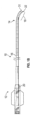
カテーテル10は、一般に、近位端12と遠位機能端14との間にわたって延びている長尺チューブ体16を含む。カテーテル10は、予め設定された曲線を有さなくてもよい(図1A)、または、予め設定された曲線を有してもよい(図1B~図1C)。チューブ体16の長さは、所望の用途に依存する。例えば、約120cm~約140cmの、あるいはそれを超える、範囲の長さが、大腿部アクセスによる経皮経管腔的冠状動脈用途での使用には典型的である。頭蓋内または他の用途では、以下でさらに詳細に説明するように、血管アクセス部位に依存して、異なるカテーテルシャフトの長さが要求される場合がある。
本発明によるカテーテルは、意図されたアクセスポイントおよび標的位置に適した長さならびに直径を有することとなる。一例では、図1A~図1Cを参照すると、カテーテル10の、マニホールドもしくはハブ20から遠位先端22までの有効長さは、一般に、約180cm以下または約160cm以下であってもよく、典型的には、約70cm~約150cm、約90cm~約130cm、または約105cm~約115cm、であってもよい。カテーテル10の外径は、約0.035インチ~約0.15インチ(約0.0889cm~約0.381cm)、また、約0.09インチ~約0.13インチ(約0.2286cm~約0.3302cm)であってもよく、近位セグメントと比較して、遠位セグメントでは、より小さくてもよい。
A catheter according to the present invention will have a length and diameter suitable for the intended access point and target location. In one example, referring to FIGS. 1A-1C, the effective length of
単一の中央管腔という実施形態におけるカテーテル10の内径は、約0.1インチ(約0.254cm)以上、約0.088インチ(約0.22352cm)以上、約0.08インチ(約0.2032cm)以上、または約0.06以上、であってもよい。単一の中央管腔という実施形態におけるカテーテル10の内径は、約0.20インチ(約0.508cm)未満または0.15インチ(約0.381cm)未満であってもよく、代替的には、約0.11インチ(約0.2794cm)以下、約0.1インチ(約0.254cm)以下、約0.088インチ(約0.22352cm)以下、または約0.07インチ(約0.1778cm)以下であってもよく、また、多くの場合、約0.095インチ(約0.2413cm)以下であってもよい。
The inner diameter of
図1Cは、チューブ体16の遠位部分を示している。チューブ体16上の受動的遠位ステアリングゾーン18には、凹側26と凸側28とを有する予備形成された曲線が設けられている。チューブ体16には、追加的に、図3Dに関連してより詳細に説明する傾斜面31が設けられている。傾斜面31は、遠位先端22のところに前縁を形成するとともに、この前縁とは反対側のところに後縁24を形成する。前縁22は、予備形成された曲線の凹側26上に配置されている。
FIG. 1C shows the distal portion of
制約を受けていない構成では、予備形成された曲線は、曲線の近位側におけるチューブ体16の長手方向軸(すなわち、予備形成された曲線の凹側)と、チューブ体16の最も遠位の2mmまたは3mmの部分がなす長手方向軸と、の間に、角度Aを確立している。角度Aは、一般に、約25°~約55°の範囲内であり、好ましくは、約50°以下であり、いくつかの実装では、約30°~約40°である。角度Aは、好ましくは、約32°~約38°の範囲内であり、一例では、約35°である。追加的に、いくつかの実装では、角度Aは、約25°~約45°、約20°~約45°、約15°~約55°、または約15°~約50°、の範囲内である。この角度は、予め設定された曲線の小さな横方向付勢との組合せで、カテーテルの先端22が生来の血管系に追従することとなる程度に充分に小さな角度ではあり、かつ、側壁を突き破って血管外空間へと出てしまわない程度に充分に小さな角度である。
In the unconstrained configuration, the preformed curve has a longitudinal axis of
いくつかの実施形態では、図1Dに示すように、予備形成された曲線は、曲線の近位側におけるチューブ体16の長手方向軸(例えば、移行部30のところ、または、予備形成された曲線の凸側のところ、または、マーカバンドの近位縁に基づいて)と、遠位先端22と、の間に、角度Bを確立している。角度Bは、一般に、約25°~約55°の範囲内であり、好ましくは、約50°以下であり、いくつかの実装では、約25°~約35°である。角度Aは、好ましくは、約27°~約33°の範囲内であり、一例では、約30°である。追加的に、いくつかの実装では、角度Bは、約25°~約45°、約20°~約45°、約15°~約55°、または約15°~約50°、の範囲内である。
In some embodiments, as shown in FIG. 1D, the pre-formed curve extends along the longitudinal axis of
いくつかの実施形態では、図1にさらに示すように、予備形成された曲線は、曲線の近位側におけるチューブ体16の長手方向軸(例えば、移行部30のところ、または、予備形成された曲線の凸側のところ、または、マーカバンドの近位縁に基づいて)と、遠位先端22と、の間に、高さHを確立している。高さHは、一般に、約0.25cm~約0.6cmの範囲内であり、いくつかの実装では、約0.3cm~約0.4cm、または約0.35cm~約0.45cm、または約0.4cm~約0.5cm、または約0.45cm~約0.55cm、の範囲内である。
In some embodiments, as further shown in FIG. 1, the pre-formed curve has a longitudinal axis of
制約を受けていない状態での撓みDの横方向限界は、一般に、約0.1インチ~約0.2インチ(約0.254cm~約0.508cm)の範囲内であり、一実施形態では、約0.15インチ(約0.381cm)である。いくつかの実装では、制約を受けていない状態での撓みDは、一般に、約0.05インチ~約0.15インチ(約0.127cm~約0.381cm)、約0.06インチ~約0.13インチ(約0.1524cm~約0.3302cm)、約0.07インチ~約0.12インチ(約0.1778cm~約0.3048cm)、約0.075インチ~約0.12インチ(約0.1905cm~約0.3048cm)、等の範囲内である。制約を受けていない状態での撓みDは、典型的には、カテーテル直径に応じて、約0.3インチ(約0.762cm)以下、または約0.25インチ(約0.635cm)以下、または約0.2インチ(約0.508cm)以下、となることとなる。 The lateral limit of unconstrained deflection D is generally in the range of about 0.1 inch to about 0.2 inch (about 0.254 cm to about 0.508 cm), and in one embodiment , about 0.15 inch (about 0.381 cm). In some implementations, the unconstrained deflection D is typically about 0.05 inch to about 0.15 inch (about 0.127 cm to about 0.381 cm), about 0.06 inch to about 0.13 inch (about 0.1524 cm to about 0.3302 cm), about 0.07 inch to about 0.12 inch (about 0.1778 cm to about 0.3048 cm), about 0.075 inch to about 0.12 inch (about 0.1905 cm to about 0.3048 cm), and so on. The unconstrained deflection D is typically about 0.3 inch (about 0.762 cm) or less, or about 0.25 inch (about 0.635 cm) or less, depending on the catheter diameter, Or about 0.2 inches (about 0.508 cm) or less.
チューブ体16は、予備形成された曲線の近位限界のところに、移行部30を含む。移行部30から遠位先端22までにわたって測定した際の、予備形成された曲線の円弧長さは、一般に、約2cm未満、または約1.5cm未満、または約1cm未満であり、多くの場合、約0.5cm~約1.5cmであり、いくつかの実装では、長さは約1.1cm~約1.4cmである。いくつかの実装では、円弧長さは、約0.75cm~約1.75cm、または約0.5cm~約2cm、または約1.25cm~約2cm、の範囲内である。
本発明のチューブ体16は、狭いかつ/または曲がりくねった身体通路を通してさえも容易に前進させ得るようカテーテルが追従可能であるように、充分に可撓性である。カテーテルは、血管系の湾曲部を通しての前進に応答して、3次元空間内の任意の平面内で曲がってもよい。よって、少なくとも遠位の予備形成された曲線は、それ自体が血管の湾曲を通しての最低エネルギ状態での構成に従うように配向することのために、身体通路を進む際には、カテーテルの長手方向軸まわりに自発的に捩れてもよい。チューブ体16を通してのトルク伝達は、充分に小さく(小さな捩れ剛性)、そのため、カテーテルの遠位端は、時計回りと反時計回りとの両方の向きで、所望に軸まわりに捩れることができ、これにより、カテーテルの近位端を回転させる必要なく、遠位前進時に血管系に対して自己配向することができる。いくつかの実施形態では、カテーテルの遠位端は、カテーテルの近位端を何ら回転させる必要なく、いずれの向きにでも、少なくとも約10度の分だけ、また、少なくとも約20度の分だけ、捩れることができ、あるいはいくつかの実施形態では、少なくとも約45度の分だけ、または90度の分だけ、またはそれを超えて、捩れることができる。カテーテルの自己配向または捩れは、血餅に対しての、カテーテルの遠位端の相互作用角度を最適化してもよく、これにより、血餅の取り込みを改良または最大化することができる。
The
図2は、単一管腔カテーテルの遠位部分の側壁を通しての、予め設定された曲線を有していてもまたは有していなくても形成され得る断面を示している。コイル3024がなす、隣接したループまたはフィラーは、コイルの長さ全体にわたって一定のピッチを有してもよく、代替的には、近位ゾーンでは密にきつく巻かれてもよく、かつ、遠位部分では、隣接したループどうしの間の間隔がもっと緩くてもよい。軸方向長さがカテーテル全長の約20%~約30%であるコイル部分3024を有する実施形態(例えば、110cmのカテーテルシャフト16で、28cmのコイル長さ)では、コイルの遠位の少なくとも約1cm、または約2cm、または約3cm、または約4cmは、近位コイル部分での間隔と比較して、少なくとも約130%の間隔を、いくつかの実装では少なくとも約150%またはそれを超える間隔を、有することとなる。ニチノール(登録商標)コイルを有する110cmのカテーテルシャフト3000では、近位コイルでの間隔は、約0.004インチ(約0.01016cm)であってもよく、そして遠位部分では、少なくとも約0.006インチ(約0.01524cm)、または0.007インチ(約0.01778cm)、またはそれを超えた間隔、であってもよい。
FIG. 2 shows a cross-section through the sidewall of the distal portion of a single lumen catheter that may or may not be formed with a preset curve. Adjacent loops or fillers of
コイル3024の遠位端は、内側ライナ3014の遠位端から近位側に離間することができ、これにより、環状の放射線不透過性マーカ3040のための余地を提供することができる。コイル3024は、いくつかの実施形態では、およそ、約1cm以下の分だけ、約2cm以下の分だけ、または約3cm以下の分だけ、遠位端から近位側に後退させてもよい。一実施形態では、カテーテル10の遠位端には、カテーテル10の長手方向軸に対して少なくとも約10°または約20°の角度を有する平面上に存在する、一実施形態では約30°の角度を有する平面上に存在する、傾斜した遠位面3006が設けられている。放射線不透過性マーカ3040は、長手方向軸に対して横断方向の平面内に存在してもよい。代替的には、環状の放射性不透過性マーカ3040の少なくとも遠位に面した端部は、長手方向軸に対して傾斜した平面でありかつ遠位面3006がなす傾斜角に対して相補的である平面上に存在する、楕円であってもよい。追加的な詳細については、以下の図3Dに関連して説明する。
The distal end of
結束層3012上に、近位編組3010、遠位コイル3024、およびROマーカ3040を適用した後に、カテーテルボディ16を取り囲むために、収縮ラップチューブなどの外側ジャケット3020が設けられる。外側収縮ラップスリーブ3020は、ポリエチレン、ポリウレタン、ポリエーテルブロックアミド(例えば、PEBAX(商標))、ナイロン(登録商標)、または当該技術分野で公知の他のもの、などの、任意の様々な材料を含んでもよい。充分な熱を印加することにより、ポリマーが、近位編組内へとおよび遠位コイル内へと流れ込んで埋設される。
Over the
一実装では、外側収縮ラップジャケット3020は、複数の短いチューブ状セグメント3022、3026、3028、3030、3032、3034、3036、3038を、カテーテルシャフトサブアセンブリ上にわたって同心的に順次前進させ、熱を印加することで、カテーテル10上にそれら部分を収縮させ、これにより、滑らかな連続した外側チューブ体を提供することによって、形成される。上記のセグメント状構造は、カテーテルボディ10の、少なくとも最遠位の10cmに沿って、好ましくは、少なくとも最遠位の、約20cm、約25cm、約30cm、約35cm、約40cm、または約40cm超、に沿って、延びてもよい。外側収縮ラップジャケット3020の全長は、チューブ状セグメントから形成されてもよく、遠位チューブ状セグメント(例えば、3022、3026、3028、3030、3032、3034、3036、3038)の長さは、カテーテル10の遠位端に向けて、近位バックアップ支持および可撓性における急峻な移行を提供するために、外側収縮ラップジャケット3020の近位部分を形成する1つまたは複数のチューブ状セグメントと比較して、より短くてもよい。
In one implementation, the outer
外壁セグメントのデュロメータは、遠位向きに減少してもよい。例えば、3022および3026などの近位セグメントは、少なくとも約60Dまたは約70Dのデュロメータを有してもよく、順次のセグメントのデュロメータは、約35Dまたは約25Dまたはそれ未満のデュロメータへと、遠位向きに徐々に減少している。25cmの部分は、少なくとも、約3個の、約5個の、約7個の、またはそれを超える個数の、セグメントを有してもよく、カテーテル10の全体は、少なくとも、約6個の、約8個の、約10個の、またはそれを超える個数の、明確に異なる可撓性ゾーンを有してもよい。遠位の、1個の、2個の、4個の、またはそれを超える個数の、セグメント3036、3038は、より近位のセグメント3022~3034と比較して、より小さな収縮後ODを有してもよく、これにより、完成したカテーテルボディ16に対して、ODの逓減を形成する。より小さなODの部分3004の長さは、約3cm~約15cmの範囲内であってもよく、いくつかの実施形態では、約5cm~約10cmの範囲内であり、例えば、約7cmまたは約8cmであり、遠位セグメント3036、3038をより薄い壁厚さとすることによって達成されてもよい。
The durometer of the outer wall segment may decrease distally. For example, the proximal segments such as 3022 and 3026 may have a durometer of at least about 60D or about 70D, with the durometer of successive segments pointing distally to a durometer of about 35D or about 25D or less. is gradually decreasing. A 25 cm section may have at least about 3, about 5, about 7, or more segments, and the
別の実施形態では、カテーテル10の最遠位部分は、カテーテルの高度に可撓性の遠位部分を形成するために、約35D未満(例えば、25D)のデュロメータを含んでもよく、また、約25cm~約35cmの長さを有してもよい。遠位部分は、同じデュロメータの1つまたは複数のチューブ状セグメント(例えば、セグメント3038)を含んでもよい。近位側で隣接した一連のチューブ状セグメントは、カテーテル3000の近位側の硬質な部分と遠位側の高度に可撓性の部分との間に、移行領域を形成してもよい。移行領域を形成する一連のチューブ状セグメントは、同じ長さを有してもよく、または、約1cmなどの実質的に同様の長さを有してもよい。
In another embodiment, the distal-most portion of
一連のチューブ状セグメントのそれぞれは、比較的短い長さであることにより、移行領域にわたって、デュロメータを急峻に低下させてもよい。例えば、移行領域は、約35Dのデュロメータを有する近位チューブ状セグメント3036(遠位部分に対して近位側で隣接したもの)を有してもよい。隣接した近位セグメント3034は、約55Dのデュロメータを有してもよい。隣接した近位セグメント3032は、約63Dのデュロメータを有してもよい。隣接した近位セグメント3030は、約72Dのデュロメータを有してもよい。
Each of the series of tubular segments may be of relatively short length resulting in a steep drop in durometer over the transition region. For example, the transition region may have a proximal tubular segment 3036 (proximally adjacent to the distal portion) having a durometer of about 35D. Adjacent
より近位のセグメントは、約72Dよりも大きなデュロメータを含んでもよく、カテーテルまたは延長カテーテルセグメントの近位端のところまで延びてもよい。例えば、延長カテーテルセグメントは、約1cm~約3cmの間にわたって、約72Dよりも大きな近位部分を含んでもよい。いくつかの実施形態では、近位部分は、約2cmの長さであってもよい。いくつかの実施形態では、最遠位セグメント(例えば、3038~3030)は、PEBAX(商標)を含んでもよく、より近位のセグメントは、Vestamid(登録商標)などの、一般的に硬質の材料を含んでもよい。 The more proximal segment may include a durometer greater than about 72D and may extend to the proximal end of the catheter or extension catheter segment. For example, an extension catheter segment may include a proximal portion greater than about 72D spanning between about 1 cm and about 3 cm. In some embodiments, the proximal portion may be about 2 cm long. In some embodiments, the most distal segments (eg, 3038-3030) may comprise PEBAX™ and the more proximal segments are generally rigid materials such as Vestamid®. may include
カテーテル10の内径は、およそ0.06インチ~0.08インチ(およそ0.1524cm~0.2032cm)、およそ0.065インチ~0.075インチ(およそ0.1651cm~0.1905cm)、またはおよそ0.068インチ~0.073インチ(およそ0.17272cm~0.18542cm)、であってもよい。いくつかの実施形態では、内径は、約0.071インチ(約0.18034cm)である。
The inner diameter of
いくつかの実施形態では、最遠位部分は、本明細書の他の箇所で説明するように、テーパ状に内径が減少してもよい。このテーパは、遠位側の高度に可撓性の部分と移行領域との間で(例えば、遠位側の高度に可撓性の部分における、最近位部分にわたって)、ほぼ発生してもよい。テーパは、比較的緩やかであってもよく(例えば、約10cmまたはそれを超えて生じてもよく)、代替的には、比較的急峻であってもよい(例えば、約5cm未満にわたって生じてもよい)。内径は、テーパ状に、約0.03インチ~約0.06インチ(約0.0762cm~約0.1524cm)の内径へと減少してもよい。例えば、内径は、カテーテル3000の遠位端のところで、約0.035インチ(約0.0889cm)、約0.045インチ(約0.1143cm)、または約0.055インチ(約0.1397cm)、であってもよい。いくつかの実施形態では、内径は、少なくともカテーテル延長セグメントにわたって、一定のままであってもよい。
In some embodiments, the distal-most portion may taper to a decreasing inner diameter, as described elsewhere herein. This taper may occur approximately between the distal highly flexible portion and the transition region (e.g., over the most proximal portion of the distal highly flexible portion). . The taper may be relatively gradual (eg, occur over about 10 cm or more), or alternatively may be relatively steep (eg, occur over less than about 5 cm). good). The inner diameter may taper down to an inner diameter of about 0.03 inch to about 0.06 inch (about 0.0762 cm to about 0.1524 cm). For example, the inner diameter at the distal end of
いくつかの実施形態では、コイル3024は、カテーテル10の遠位端から、高度に可撓性の遠位部分に沿って近位向きに延び、移行領域の遠位端で終端してもよい。他の実施形態では、コイル3024は、カテーテルの遠位端から、移行領域の近位端まで、または移行領域に沿った箇所まで、または移行領域を超えて近位側へと、延びてもよい。他の実施形態では、コイル3024は、本明細書の他の箇所で説明するように、カテーテル10またはカテーテル延長セグメントの全長にわたって、延びてもよい。編組3010は、存在する場合には、コイル3024の近位端から、カテーテル10の近位端まで、延びてもよい。
In some embodiments, the
図3A~図3Dを参照すると、カテーテルは、遠位ゾーンにおける引張抵抗を増大させるためにおよび/または遠位ゾーンにおける曲げ特性に影響を与えるために、リボンなどの、1つもしくは複数のフィラメントなどの、または1つもしくは複数のファイバなどの、軸方向張力部材または軸方向支持体を、さらに含んでもよい。張力支持体は、軸方向に延びた、1つもしくは複数のモノストランドフィラメントまたはマルチストランドフィラメント3042を含んでもよい。1つまたは複数の張力部材3042は、カテーテルの遠位端付近におけるカテーテル壁の内部に、軸方向に配置されてもよい。フィラメントは、予め設定された曲線を有するカテーテルの凸側に配置されてもよい。1つまたは複数の張力部材3042は、張力下で(例えば、カテーテルが、曲がりくねったまたは狭窄した血管系内を通して近位向きに後退する時に)、張力支持体として機能してもよく、カテーテル壁の伸張に抵抗してもよい。
3A-3D, the catheter comprises one or more filaments, such as ribbons, to increase tensile resistance in the distal zone and/or to affect bending properties in the distal zone. It may further include an axial tension member or axial support, such as one or more fibers. The tension support may include one or more mono-strand or
1つまたは複数の張力部材3042の、少なくとも1つは、カテーテル壁の長さに沿って、カテーテルの遠位端から約1.0cm以内のところから、カテーテルの遠位端から約10cm未満のところまで、カテーテルの遠位端から約20cm未満のところまで、カテーテルの遠位端から約30cm未満のところまで、カテーテルの遠位端から約40cm未満のところまで、またはカテーテルの遠位端から約50cm未満のところまで、近位向きに延びてもよい。
At least one of the one or
1つまたは複数の張力部材3042は、約40cm以上の長さ、約30cm以上の長さ、約20cm以上の長さ、約10cm以上の長さ、または約5cm以上の長さ、を有してもよい。
The one or
1つまたは複数の張力部材3042の、少なくとも1つは、カテーテル長さの最遠位の少なくとも約50cmにわたって、カテーテル長さの最遠位の少なくとも約40cmにわたって、カテーテル長さの最遠位の少なくとも約30cmまたは少なくとも約20cmまたは少なくとも約10cmにわたって、延びてもよい。
At least one of the one or
いくつかの実装では、張力部材は、コイル24の長さに沿ってカテーテルの遠位端から近位向きに延びているとともに、コイル3024と編組3010との間の移行部3011のいずれかの側で、約5cmまたは約2cmまたはそれ未満の範囲内で、近位側が終端している。張力部材は、編組3010に対してオーバーラップすることなく、移行部3011で終端してもよい。
In some implementations, tension members extend proximally from the distal end of the catheter along the length of
1つまたは複数の張力部材3042は、結束層3012または内側ライナ3014の、付近にあるいは径方向外側に、配置されてもよい。1つまたは複数の張力部材3042は、編組3010および/またはコイル3024の、付近にあるいは径方向内側に、配置されてもよい。1つまたは複数の張力部材3042は、内側ライナ3014と螺旋コイル3024との間に担持されてもよく、また、コイルなどの次なる外側隣接層を追加する前に、接着剤によって、内側ライナに対してまたは他の下地面に対して、固定されてもよい。
One or
2つ以上の張力部材3042またはフィラメント束が、カテーテル壁内で周方向に離間している場合には、張力部材3042は、径方向に対称な態様で、配置されてもよい。例えば、カテーテルの半径中心に対しての、2つのフィラメント3042どうしがなす角度は、約180度であってもよい。代替的には、所望の臨床性能(例えば、可撓性、追従性)に応じて、張力部材3042は、径方向に非対称な態様で、配置されてもよい。カテーテルの半径中心に対しての、2つの張力部材3042がなす角度は、約180度未満、約165度以下、約135度以下、約120度以下、約90度以下、約45度以下、または約15度以下、であってもよい。
If two or
1つまたは複数の張力部材3042は、ベクトラン、ケブラー、ポリエステル、メタ-パラ-アラミド、またはこれらの任意の組合せ、などの材料を含んでもよい。1つまたは複数の張力部材3042の、少なくとも1つは、単一ファイバ、または複数のファイバからなる束、を含んでもよく、ファイバまたは束は、円形あるいは矩形(例えば、リボン)の断面形状を有してもよい。ファイバまたはフィラメントという用語は、組成を伝えるものではなく、設計上の考慮事項に応じて、例えば、所望の引張破壊限界および壁厚さに応じて、様々な高張力ポリマー、金属、または合金、のいずれを含んでもよい。径方向で測定した際の、1つまたは複数の張力部材3042の断面寸法は、カテーテル10の断面寸法と比較して、およそ、2%以下、5%以下、8%以下、15%以下、または20%以下、であってもよい。
The one or
径方向で測定した際の、1つまたは複数の張力部材3042の断面寸法は、約0.001インチ(約0.00254cm)以下、約0.002インチ(約0.00508cm)以下、約0.004インチ(約0.01016cm)以下、約0.006インチ(約0.01524cm)以下、約0.008インチ(約0.02032cm)以下、または約0.015インチ(約0.0381cm)以下、であってもよい。
The cross-sectional dimension of the one or
1つまたは複数の張力部材3042は、、張力下での破損前における、カテーテルの遠位ゾーンにおける引張強度を、少なくとも約1ポンドへと、少なくとも約2ポンドへと、少なくとも約3ポンドへと、少なくとも約4ポンドへと、少なくとも約5ポンドへと、少なくとも約6ポンドへと、少なくとも約7ポンドへと、少なくとも約8ポンドへと、または少なくとも約10ポンドへと、あるいはそれを超えて、増大させてもよい。
The one or
本明細書で開示するいずれのカテーテルにも、軸方向張力部材が含まれているどうかにかかわらず、傾斜付き遠位先端が設けられてもよい。図3Dを参照すると、遠位カテーテル先端3110は、チューブ体3112を含み、チューブ体3112は、前進セグメント3114と、マーカバンド3116と、近位セグメント3118と、を含む。内側チューブ状ライナ3120は、遠位カテーテル先端3110の長さ全体にわたって延びてもよいとともに、浸漬塗布されたPTFEを含んでもよい。
Any of the catheters disclosed herein, whether or not an axial tension member is included, may be provided with a beveled distal tip. 3D,
編組またはスプリングコイルなどの補強部材3122が、遠位カテーテル先端3110の全長にわたって延び得る外側ジャケット3124内に、埋設されている。
A reinforcing
前進セグメント3114は、遠位側が傾斜面3126内で終端しており、これにより、マーカバンド3116の遠位端3130と遠位先端3132との間で測定される長さを有する先導的側壁部分3128を提供している。前進セグメント3114の後続的側壁部分3134は、図示の実施形態では、先導的側壁部分3128からカテーテルまわりに約180度のところで測定した先導的側壁部分3128の軸方向長さと比較して、ほぼ等しい軸方向長さを有している。先導的側壁部分3128は、約0.1mm~約5mmの範囲内の軸方向長さを有してもよく、一般的には、およそ、1mm~3mmの範囲内の軸方向長さを有してもよい。後続的側壁部分3134は、所望の性能に応じて、先導的側壁部分3128の軸方向長さと比較して、少なくとも、およそ、0.1mmまたは0.5mmまたは1mmまたは2mmまたはそれを超えて、短くてもよい。
The advancing
傾斜面3126は、カテーテルの長手方向軸から約45度~約80度の範囲内とされた角度Aで傾斜している。特定の実装では、この角度は、カテーテルの長手方向軸から、約55度~約65度の範囲内、または約55度~約65度の範囲内である。一実装では、角度Aは、約60度である。角度Aが約90度未満であることの1つの結果は、遠位ポートがなす領域における長軸の延長であり、これは、ポートの表面積を増加させて、血餅の吸引または保持を増強し得る。円形ポートの場合(角度Aが90度である場合)の表面積と比較して、傾斜付きポートの面積は、一般に、少なくとも約105%でありかつ約130%以下であり、いくつかの実装では、約110%~約125%の範囲内であり、一例では、約115%である。
The
図示の実施形態では、前進セグメントの軸方向長さは、カテーテルの周方向まわりにおいて実質的に一定であり、これにより、傾斜面3126は、マーカバンド3116の遠位面3136に対して、ほぼ平行である。マーカバンド3116は、カテーテルの長手方向軸に対して略横断方向の近位面を有しており、これにより、側面視において直角台形構成を有するマーカバンド3116が形成される。短い側壁3138は、後続的側壁部分3134に対して回転的に位置合わせされているとともに、約0.2mm~約4mmの範囲内の、典型的には約0.5mm~約2mmの範囲内の、軸方向長さを有している。反対側に位置した長い側壁3140は、先導的側壁部分3128に対して回転的に位置合わせされている。マーカバンド3116の長い側壁3140は、一般に、短い側壁3138と比較して、少なくとも、およそ、10%または20%の分だけ、より長いものであるとともに、所望の性能に応じて、短い側壁部分3138と比較して、少なくとも、およそ、50%または70%または90%またはそれを超えた分だけ、より長くてもよい。一般に、長い側壁3140は、少なくとも、およそ、0.5mmまたは1mmの長さを、かつ、約5mm未満または4mm未満の長さを、有することとなる。
In the illustrated embodiment, the axial length of the advancement segment is substantially constant about the circumference of the catheter such that the
本明細書で説明するマーカバンドのいずれも、連続的な環状構造であってもよく、または任意選択的に、その長さ全体にわたって、少なくとも1つの、また任意選択的には2つまたは3つまたはそれを超える個数の、軸方向に延びたスリット3117を有してもよい。スリットは、所望の曲げ特性に応じて、短い側壁3138上に、または長い側壁3140上に、またはそれらの間に、配置されてもよい。本明細書で説明するマーカバンドのいずれも、好ましくは約0.003インチ(約0.00762cm)以下の、一実装では約0.001インチ(約0.00254cm)の、壁厚さを有する、例えば白金/イリジウム合金などの、任意の様々な放射線不透過性材料を含んでもよい。一実装では、少なくとも1つの軸方向スリットは、予め設定された曲線の凸側に対して位置合わせされており、フィラメントは、マーカの近位面を超えて、軸方向スリット内へと、遠位向きに延びている。
Any of the marker bands described herein may be a continuous ring structure, or optionally at least one, and optionally two or three, throughout its length. Or it may have a greater number of axially extending
組み立てられたカテーテルのマーカバンドゾーンは、近位セグメント18と比較して少なくとも約50%の分だけ小さくまたは少なくとも約100%の分だけ小さく、かつ、一般的には近位セグメント3118と比較して約200%以下の分だけ小さいなどの、比較的大きな曲げ剛性および比較的大きな破砕強度を有してもよい。大きな破砕強度は、隣接した前進セグメント3114に対して、特に先導的側壁部分3128に対して、径方向の支持を提供することができ、これにより、経管前進時に遠位先端3132が非外傷性の緩衝器として機能することを容易とするとともに、真空下での圧潰に対して抵抗することができる。近位セグメント3118は、好ましくは、マーカバンドゾーンと比較して、より小さな曲げ剛性を有しており、前進セグメント3114は、好ましくは、近位セグメント3118と比較して、さらに小さな曲げ剛性および破砕強度を有している。
The marker band zone of the assembled catheter is at least about 50% smaller or at least about 100% smaller as compared to
前進セグメント3114は、マーカバンド3116の遠位向きに他の内部支持構造を有することなく、外側ジャケット3124に関して、および任意選択的に内側ライナ3120に関して、遠位延長部分を含んでもよい。外側ジャケットは、押出成形されたテコタン(Tecothane)を含んでもよい。前進セグメント3114は、近位セグメント3118に関して対応する値と比較して、約50%以下であるような、いくつかの実装では、およそ、25%以下、もしくは15%以下、もしくは5%以下、もしくはそれ未満であるような、曲げ剛性および径方向の破砕剛性を有してもよい。
本明細書の他の箇所で説明したような寸法および材料を有する張力部材3142が、近位セグメント3118の長さの、少なくとも遠位部分を通して延びている。図示しているように、張力部材3142は、マーカバンド3116の近位面のところで遠位側が終端してもよく、チューブ状ライナ3120の径方向外側へと軸方向に、および、支持コイル3122から径方向内側へと、延びてもよい。代替的には、マーカバンドには、少なくとも1つの、または2つの、軸方向に延びたスリット3117が設けられてもよく、ファイバは、スリット内へと延びることができ、これにより、マーカバンドに対して軸方向にオーバーラップすることができる。張力部材3142は、長手方向軸に実質的に平行に延びてもよい、代替的には、螺旋の長さに沿ってカテーテルまわりに、10回転以下、または7回転以下、または3回転以下、または1回転以下、またはそれ未満の、完全回転を有する穏やかな螺旋へと、傾斜してもよい。ファイバは、ベクトランマルチフィラメントLCPファイバなどの液晶ポリマーから紡糸されたマルチフィラメント糸といったような、高張力材料を含んでもよい。
A
図3Eに示す実装では、張力部材3142は、コイルの外側(または内側)に沿って遠位向きにかつ軸方向に延びているとともに、上述したような傾斜遠位面を有し得るマーカバンド3116などの、連続したまたはスリット付きの環状リングの形態であり得るアンカーに向けて軸方向に延びている。張力部材3142は、好ましくはアンカーに対して固定されており、これにより、先端の脱離による破損の前に、引張力のしきい値を増大させる。これにより、マーカバンドを圧潰し得るものの脱離はさせないような、血管内の制限物などのまたはガイドカテーテル内のキンクなどの、制限物を通して、カテーテルを近位向きに引っ張ることができる。引張強度を増強することは、また、マーカバンドを剪断しかねない制限物に対して遭遇した時点で、医師に対して触覚的フィードバックを提供する。スリット3117を有する実装では、張力部材3142の軸を、スリット3117から周方向にオフセットしてもよく、これにより、スリットを通してファイバが引っ張られることを回避してもよい。
In the implementation shown in FIG. 3E,
張力部材3142は、関与している構造および材料に応じて、接着剤や溶接やまたは機械的な干渉嵌めを含めた任意の様々な態様で、アンカーに対して固定されてもよい。図示した実装では、張力部材3142は、マーカバンド3116の遠位縁などの、またはマーカバンド3116を貫通した開口の近位縁などの、マーカバンド3116の少なくとも遠位向き縁のまわりに、巻回されている。一実装では、張力部材3142は、マーカバンドを超えてマーカバンドの第1側に沿って軸方向に延びているとともに、マーカバンドの遠位縁まわりにおいてマーカバンドの第2側へと折り返されており、チューブ体に対して(例えば、マーカバンドに対して、または自身に対して)固定されている。
図示した例では、張力部材3142の第1セグメント3150は、コイルの上方でまたは好ましくはコイルの下方で、カテーテルボディに沿って軸方向に、マーカバンド3116の下方で、マーカバンドの内面に沿って遠位向きに、マーカバンドの遠位縁3156まで、延びている。張力部材は、遠位縁3156上へと折り返されているとともに、傾斜付きセグメント3152に沿ってマーカバンドの外面上を近位向きに延びており、さらに、マーカバンド3116上など、および/または隣接したカテーテル側壁上など、チューブ体まわりにおいて周方向に、端部3154へと巻回されている。張力部材は、少なくとも約180度という角度の分だけ、好ましくは、少なくとも約270度という、または少なくとも約360度という、または少なくとも約450度という、またはそれを超えた、角度の分だけ、周方向に巻回されてもよい。張力部材は、外側ポリマージャケットを適用する前に、Loctiteなどの接着剤によって、マーカバンド上へと、または隣接したカテーテルシャフト上へと、取り付けられてもよい。
In the illustrated example, the
代替的には、張力部材は、マーカバンドまわりに、および、自身の上へと近位向きに、折り返されているとともに、外側ジャケット内へと封入される前に、自身に対して結合され得る少なくとも約1cmまたは約2cmまたは約5cmまたはそれを超えた結合ゾーンのために、近位向きに延びてもよい。 Alternatively, the tension member may be folded proximally around and onto itself and bonded to itself prior to encapsulation within the outer jacket. It may extend proximally for a bonding zone of at least about 1 cm or about 2 cm or about 5 cm or more.
図示した実装では、張力部材は、スリット3117の中心から周方向にオフセットした約20度~約40度の範囲内におけるポイントのところで、マーカバンドと交差している。代替的には、張力部材は、スリットからオフセットした約80度~約100度の範囲内で、またはスリットからオフセットした約170度~約190度の範囲内で、マーカバンドと交差してもよい。スリットがマーカバンドの最短軸方向寸法のところに位置していない実装では、上記のオフセットは、最短軸方向寸法から測定されてもよい。
In the illustrated implementation, the tension member intersects the marker band at a point within a range of about 20 degrees to about 40 degrees circumferentially offset from the center of
マーカバンドの径方向圧縮性は、望ましくは、マーカバンドの遠位端からマーカバンドの近位端へと近位向きに増加してもよく、これにより、連続的なまたは段階的な、圧縮性を形成してもよい。これは、カテーテルを近位向きに引き込む時に、マーカバンドが障害物(例えば、血管の障害物、または、ガイドカテーテル内のキンク)に遭遇した時などに、マーカバンドの近位端における径方向圧縮性を容易とし得る。さらに近位向きに引き込むことにより、マーカバンドの側壁は、マーカバンドの遠位端の直径まで傾斜することができ、障害物を横方向に変位させることで、および/またはマーカバンドを徐々に圧潰することで、マーカバンドは、障害物を通り抜けることができる。これは、付設された張力部材との組合せで、マーカバンドの脱離を回避する可能性を最適化する。 The radial compressibility of the marker band may desirably increase proximally from the distal end of the marker band to the proximal end of the marker band, thereby providing continuous or stepped compressibility. may be formed. This results in radial compression at the proximal end of the marker band, such as when the marker band encounters an obstruction (e.g., a vascular obstruction or a kink in the guide catheter) as the catheter is retracted proximally. can facilitate sex. Further proximal retraction allows the side walls of the marker band to slope to the diameter of the distal end of the marker band, laterally displacing the obstruction and/or gradually collapsing the marker band. By doing so, the marker band can pass through obstacles. In combination with the attached tension member, this optimizes the possibility of avoiding detachment of the marker band.
上述したマーカバンド3116の基本的な幾何形状が、図4Aに示されている。マーカバンド3116は、近位の横断面3150と、遠位の傾斜面3136と、の間にわたって延びている。長い側壁3140は、遠位先端3130で、遠位側が終端している。反対側に位置した短い側壁3138は、上述したような軸方向スリットを含んでもよい。
The basic geometry of
図4Bを参照すると、マーカバンド3116には、マーカバンドの近位端の径方向圧縮性を増大させる圧縮機構が設けられている。図示した実装では、圧縮機構は、少なくとも第1圧縮ギャップ3152を含むとともに、近位を向いた凹所3154の形態で、少なくとも第2圧縮ギャップを含んでもよい。第1圧縮ギャップ3152は、近位面3150から遠位向きに、長い側壁3140の長さに対して、少なくとも約25%にわたって、いくつかの実装では少なくとも約50%にわたってまたは少なくとも約70%にわたってまたはそれを超えて、延びている。
Referring to FIG. 4B, the
第2圧縮ギャップは、近位面3150から遠位向きに、第1圧縮ギャップ3152から第1周方向に約90度だけ回転して、延びてもよい。少なくとも第3圧縮ギャップが、第1圧縮ギャップ3152から第2周方向に約90度だけ回転して、設けられてもよい。
The second compression gap may extend distally from the
上記の構造は、マーカバンド3116の近位縁の形態で、近位面3150がなす平面上に位置する円弧状ベース3156を提供するものであり、この円弧状ベース3156は、カテーテルボディ内の、コイルの遠位端に対して、または他の側壁補強部材の遠位端に対して、接触することとなる。第1足部3158および第2足部3160も、また、形成されており、これらも、近位面3150に対応した平面上にほぼ位置しており、マーカバンド3116を、スプリングコイルの遠位端に対して、または他のカテーテルボディ補強部材の遠位端に対して、支持している。これにより、マーカバンド3116の近位端の径方向圧縮を可能としつつ、さらに、コイルの遠位面に対する傾斜に関してマーカバンド3116を支持する。
The above structure provides an
図4Dに示す実装では、図4Aのマーカバンドの特徴点を有するマーカバンド3116は、径方向圧縮を容易とする少なくとも第1圧縮ギャップ3152を提供することによって、改変されている。所望の性能に応じて、第2圧縮ギャップ3162が設けられてもよく、また、任意選択的に、第3圧縮ギャップ3164または更なるギャップが設けられてもよい。圧縮ギャップの近位開口は、マーカバンド3116の近位面3150などの横断面上に、位置してもよい。各圧縮ギャップは、好ましくは、近位端のところで周方向に測定された幅として、圧縮ギャップの遠位端近傍での幅と比較して、より大きな幅を有している。圧縮ギャップの軸方向深さは、互いにほぼ等しくてもよく、これにより、圧縮ギャップのすべての遠位端は、近位面3150に対してほぼ平行な横断面内で、位置合わせされる。代替的には、図4Dに示すように、圧縮ギャップの遠位端は、傾斜した遠位面3136に対してほぼ平行であり得る傾斜面上に位置するようにして、徐々に位置合わせされてもよい。
In the implementation shown in FIG. 4D, the
代替的には、図4F~図4Iのマーカバンドに示すように、1つまたは複数の圧縮ギャップは、近位横断面3150と遠位傾斜面3136との間にわたって延び得るものの、近位横断面3150に対して交差しなくてもよい(例えば、図4Eのマーカバンドとは対照的である)。上述したように、各圧縮ギャップ3176、3178、3180は、図4H~図4Iに示すように、近位端のところで周方向に測定された幅として、圧縮ギャップの遠位端近傍での幅と比較して、より大きな幅を有してもよい。代替的には、各圧縮ギャップ3170、3172、3174は、図4F~図4Gに示すように、近位端のところで周方向に測定された幅として、圧縮ギャップの遠位端近傍での幅と比較して、実質的に等しい幅を、または実質的に同様の幅を、有してもよい。圧縮ギャップ3170、3174、3176、3180の、それぞれ対応する遠位端3170a、3174a、3176a、3180aの、角度および/または形状は、上述したようにまた図4F~図4Iに示すように、遠位面3136の角度と比較して、実質的に等しくてもよい、または同様であってもよい。図4F~図4Iの各実施形態における、周方向に連続した近位横断面3150は、本明細書の他の箇所で説明するようにまた後述するように、コイルに対しての固定を可能とするようなものとされている。
Alternatively, as shown in the marker bands of FIGS. 4F-4I, one or more compression gaps may extend between the proximal
張力部材に加えて、または張力部材に代えて、本明細書で開示するマーカバンドのいずれかは、接着剤や溶接やまたは機械的な干渉嵌めなどによって、コイルに対して固定されてもよい。機械的な干渉嵌めに関する一実装では、螺旋状のスロットが、マーカバンドの近位側壁に、少なくとも約45度にわたって周方向に延びた態様で、いくつかの実装では少なくとも約180度にわたってまたは約360度にわたってまたはそれを超えて周方向に延びた態様で、形成されてもよい。これにより、螺旋コイルの遠位端を、接合部にわたっての内腔のIDおよびカテーテルのODを維持しながら、マーカバンド側壁の螺旋スロット内へとネジ留めすることができる。 In addition to or in lieu of tension members, any of the marker bands disclosed herein may be secured to the coil, such as by adhesives, welding, or a mechanical interference fit. In one implementation for a mechanical interference fit, the helical slot extends circumferentially through the proximal sidewall of the marker band for at least about 45 degrees, and in some implementations for at least about 180 degrees or about 360 degrees. It may be formed in a manner that extends circumferentially over 100 degrees or more. This allows the distal end of the helical coil to be screwed into the helical slot of the marker band side wall while maintaining the ID of the lumen across the junction and the OD of the catheter.
更なる代替例として、単一のチューブストックから、マーカバンドと、長尺で近位向きに延びる軸方向のまたは螺旋状のストラット張力部材と、をレーザー切断することなどによって、1つまたは複数の張力部材を、マーカバンドと一体的に形成してもよい。 As a further alternative, one or more strut tension members, such as by laser cutting marker bands and elongated proximally extending axial or helical strut tension members from a single tube stock. The tension member may be integrally formed with the marker band.
張力部材は、少なくとも1つの、また任意選択的に少なくとも2つのまたは4つのまたは10個のまたはそれよりも多数の、ストラットの形態をとってもよく、これらは、直線状のまたは螺旋状のまたは交差状の例えばダイヤモンド状のパターンで、近位向きに延びてもよい。 The tension member may take the form of at least one, and optionally at least two or four or ten or more struts, which may be straight or helical or crossed. may extend proximally in, for example, a diamond-like pattern of .
例えば、図4Eのマーカバンド(明瞭化のために、任意選択的な圧縮ギャップは、省略されている)は、複数の側壁開口3168を有するチューブ体を規定する複数の交差したストラット3166の形態とされた張力部材を含み、これらは、近位向きの圧縮性が、漸次的に、増加または減少してもよい。マーカバンドおよび関連した張力部材ストラット3166は、コイルを巻回する前の時点における接着剤の適用の有無に関係なく、張力部材の長さの少なくとも一部における外側まわりにコイルが巻回された状態で、結束層上にスリップフィットされてもよい。代替的には、複数の近位頂点が、カテーテルシャフト内の支持構造(例えば、コイル)の遠位端に関する幾何形状に対して相補的な横断面または他の幾何形状に対して位置合わせされた状態で、形成されてもよく、確実な接合部を提供するよう、端部どうしが溶接されてもよい。さらに、図4A~図4Iの実施形態のいずれかは、本明細書の他の箇所で説明するように、軸方向に延びたスリットを含んでも含まなくてもよい。
For example, the marker band of FIG. 4E (optional compression gaps omitted for clarity) is in the form of multiple crossed
図5A~図5Bを参照すると、図2に関連して説明したタイプの漸次的可撓性カテーテルのための、外側ジャケットセグメントの積層パターンの一例が図示されている。遠位セグメント3038は、およそ、1cm~3cmの範囲内の長さと、およそ、35D未満のまたは30D未満のデュロメータと、を有してもよい。隣接した近位セグメント3036は、およそ、4cm~6cmの範囲内の長さと、およそ、35D未満のまたは30D未満のデュロメータと、を有してもよい。隣接した近位セグメント3034は、およそ、4cm~6cmの範囲内の長さと、約35D以下のデュロメータと、を有してもよい。隣接した近位セグメント3032は、およそ、1cm~3cmの範囲内の長さと、約35D~約45Dの範囲内の(例えば、40Dの)デュロメータと、を有してもよい。隣接した近位セグメント3030は、およそ、1cm~3cmの範囲内の長さと、約50D~約60Dの範囲内の(例えば、約55Dの)デュロメータと、を有してもよい。隣接した近位セグメント3028は、およそ、1cm~3cmの範囲内の長さと、約35D~約50Dの範囲内の、更には約35D~約60Dの範囲内の(例えば、約55Dの)、デュロメータと、を有してもよい。隣接した近位セグメント3026は、およそ、1cm~3cmの範囲内の長さと、少なくとも約60Dの、典型的には約75D未満の、デュロメータと、を有してもよい。より近位のセグメントは、少なくとも約65Dまたは約70Dのデュロメータを有してもよい。最遠位の2つまたは3つのセグメントは、テコタンなどの材料を含んでもよく、より近位のセグメントは、PEBAX(商標)、または当該技術分野で公知の他のカテーテルジャケット材料、を含んでもよい。少なくとも、3個の、5個の、7個の、9個の、またはそれを超えた個数の、個別セグメントを利用してもよく、これらのセグメントは、カテーテルシャフトの長さに沿った最高値と最低値との間にわたるデュロメータの変化が、少なくとも約10D、好ましくは少なくとも約20D、いくつかの実装では少なくとも約30D、または40D、あるいはそれを超えたもの、であるようなセグメントとされている。
5A-5B, one example of an outer jacket segment lamination pattern for a progressively flexible catheter of the type described in connection with FIG. 2 is illustrated.
例示的な実施形態 exemplary embodiment
引張強度を増強させた神経血管カテーテルであって、 A neurovascular catheter with enhanced tensile strength, comprising:
近位端と、遠位端と、中央管腔を規定している側壁と、を有する長尺可撓性チューブ体と、 an elongated flexible tubing having a proximal end, a distal end, and a sidewall defining a central lumen;
遠位端に対して隣接しているとともに、チューブ体の外周の少なくとも一部にわたって延びている、放射線不透過性マーカと、 a radiopaque marker adjacent to the distal end and extending over at least a portion of the circumference of the tubular body;
側壁内において軸方向に延びている張力支持体と、
の1つまたは複数を含み、
a tension support extending axially within the sidewall;
including one or more of
張力支持体は、放射線不透過性マーカの第1側に沿って遠位向きに延びているとともに、放射線不透過性マーカの遠位縁まわりに折り返され、さらに、放射線不透過性マーカの第2側に沿って延びている、神経血管カテーテル。 A tension support extends distally along a first side of the radiopaque marker and is folded around a distal edge of the radiopaque marker and further extends distally along a second side of the radiopaque marker. A neurovascular catheter extending laterally.
張力支持体は、複数のファイバを含む、本明細書で説明する任意の例における神経血管カテーテル。 A neurovascular catheter in any example described herein, wherein the tension support comprises a plurality of fibers.
張力支持体は、ベクトランマルチフィラメント液晶ポリマーファイバを含む、本明細書で説明する任意の例における神経血管カテーテル。 A neurovascular catheter in any example described herein, wherein the tension support comprises a Vectran multifilament liquid crystal polymer fiber.
張力支持体は、マーカの径方向内向き面に沿って遠位向きに延びているとともに、マーカの遠位端まわりに延びており、さらに、マーカの径方向外向き面まわりにおいて周方向に延びている、本明細書で説明する任意の例における神経血管カテーテル。 The tension bearing extends distally along the radially inward facing surface of the marker, extends around the distal end of the marker, and extends circumferentially around the radially outward facing surface of the marker. A neurovascular catheter in any example described herein.
張力支持体は、マーカまわりにおいて、少なくとも約180度にわたって周方向に延びている、本明細書で説明する任意の例における神経血管カテーテル。 The neurovascular catheter of any example described herein, wherein the tension support extends circumferentially at least about 180 degrees around the marker.
放射線不透過性マーカは、近位面と遠位面とを含み、遠位面は、中央管腔の長手方向軸に対して、約45度~約80度の範囲内の角度で傾斜している、本明細書で説明する任意の例における神経血管カテーテル。 The radiopaque marker includes a proximal surface and a distal surface, with the distal surface angled at an angle within the range of about 45 degrees to about 80 degrees with respect to the longitudinal axis of the central lumen. A neurovascular catheter in any example described herein.
楕円形開口を有する遠位ポートを含み、楕円形開口は、中央管腔の横断方向の断面積と比較して、少なくとも約105%である面積を含む、本明細書で説明する任意の例における神経血管カテーテル。 In any example described herein comprising a distal port having an elliptical opening, the elliptical opening comprising an area that is at least about 105% compared to the transverse cross-sectional area of the central lumen Neurovascular catheter.
楕円形開口の面積は、中央管腔の断面積と比較して、少なくとも約110%である、本明細書で説明する任意の例における神経血管カテーテル。 The neurovascular catheter of any example described herein, wherein the area of the oval opening is at least about 110% compared to the cross-sectional area of the central lumen.
楕円形開口は、中央管腔の長手方向軸に対して、約55度~約65度の範囲内の角度で傾斜している、本明細書で説明する任意の例における神経血管カテーテル。 The neurovascular catheter of any example described herein, wherein the oval opening is angled with respect to the longitudinal axis of the central lumen at an angle within the range of about 55 degrees to about 65 degrees.
放射線不透過性マーカ上の近位面は、長手方向軸に対して、ほぼ垂直である、本明細書で説明する任意の例における神経血管カテーテル。 A neurovascular catheter as in any example described herein, wherein the proximal face on the radiopaque marker is substantially perpendicular to the longitudinal axis.
遠位端は、放射線不透過性マーカの遠位面から離間しており、これにより、チューブ体の前進セグメントを形成している、本明細書で説明する任意の例における神経血管カテーテル。 A neurovascular catheter as in any example described herein, wherein the distal end is spaced from the distal face of the radiopaque marker thereby forming an advancing segment of the tubular body.
前進セグメントは、約0.1mm~約5mmの範囲内の軸方向長さを有している、本明細書で説明する任意の例における神経血管カテーテル。 The neurovascular catheter of any example described herein, wherein the advancement segment has an axial length within the range of about 0.1 mm to about 5 mm.
チューブ体の前縁側における前進セグメントの軸方向長さは、チューブ体の後縁側における前進セグメントの軸方向長さと比較して、より大きい、本明細書で説明する任意の例における神経血管カテーテル。 A neurovascular catheter as in any example described herein, wherein the axial length of the advancement segment on the leading side of the tubular body is greater than the axial length of the advancement segment on the trailing side of the tubular body.
放射線不透過性マーカは、少なくとも1つの軸方向スリットを有する環状リングを含む、本明細書で説明する任意の例における神経血管カテーテル。 A neurovascular catheter as in any example described herein, wherein the radiopaque marker comprises an annular ring having at least one axial slit.
内側ライナをさらに含み、張力支持体は、螺旋コイルと内側ライナとの間にわたって軸方向に延びている、本明細書で説明する任意の例における神経血管カテーテル。 The neurovascular catheter of any example described herein, further comprising an inner liner, the tension bearing extending axially between the helical coil and the inner liner.
破損前に少なくとも約3.5ポンドの張力に耐えるように構成されている、本明細書で説明する任意の例における神経血管カテーテル。 The neurovascular catheter of any example described herein configured to withstand at least about 3.5 pounds of tension before failure.
破損前に少なくとも約5ポンドの張力に耐えるように構成されている、本明細書で説明する任意の例における神経血管カテーテル。 The neurovascular catheter of any example described herein configured to withstand at least about 5 pounds of tension before failure.
破損前に少なくとも約7ポンドの張力に耐えるように構成されている、本明細書で説明する任意の例における神経血管カテーテル。 The neurovascular catheter of any example described herein configured to withstand at least about 7 pounds of tension before failure.
側壁は、複数のチューブ状セグメントを有する外側ジャケットを含み、複数のチューブ状セグメントの近位チューブ状セグメントは、少なくとも約60Dのデュロメータを有しており、複数のチューブ状セグメントの遠位チューブ状セグメントは、最大で約35Dのデュロメータを有している、本明細書で説明する任意の例における神経血管カテーテル。 The sidewall includes an outer jacket having a plurality of tubular segments, a proximal tubular segment of the plurality of tubular segments having a durometer of at least about 60D, and a distal tubular segment of the plurality of tubular segments. is a neurovascular catheter in any example described herein having a durometer of up to about 35D.
神経血管カテーテルであって、 A neurovascular catheter, comprising:
近位端と、傾斜した遠位端と、中央管腔を規定している側壁と、を有する長尺可撓性チューブ体と、 an elongated flexible tubing having a proximal end, an angled distal end, and a sidewall defining a central lumen;
傾斜した遠位端の第1側部上に位置した遠位先端と、 a distal tip located on a first side of the beveled distal end;
チューブ体の遠位ゾーンに位置した予め設定された曲線と、
の1つまたは複数を含み、
a preset curve located in the distal zone of the tubular body;
including one or more of
遠位先端は、曲線の凹側に位置している、神経血管カテーテル。 A neurovascular catheter in which the distal tip is located on the concave side of the curve.
側壁内に埋設されたチューブ状放射線不透過性マーカをさらに含み、チューブ状放射線不透過性マーカは、近位面と遠位面とを含み、放射線不透過性マーカの遠位面は、中央管腔の長手方向軸に対して、約45度~約80度の範囲内の角度で傾斜している、本明細書で説明する任意の例における神経血管カテーテル。 Further including a tubular radiopaque marker embedded within the sidewall, the tubular radiopaque marker including a proximal surface and a distal surface, the distal surface of the radiopaque marker being in the central canal. The neurovascular catheter of any example described herein that is angled with respect to the longitudinal axis of the lumen at an angle within the range of about 45 degrees to about 80 degrees.
楕円形開口を有する遠位ポートを含み、楕円形開口は、中央管腔の断面積と比較して、少なくとも約105%である面積を含む、本明細書で説明する任意の例における神経血管カテーテル。 A neurovascular catheter in any of the examples described herein comprising a distal port having an elliptical opening, the elliptical opening comprising an area that is at least about 105% compared to the cross-sectional area of the central lumen .
楕円形開口の面積は、中央管腔の断面積と比較して、少なくとも約110%である、本明細書で説明する任意の例における神経血管カテーテル。 The neurovascular catheter of any example described herein, wherein the area of the oval opening is at least about 110% compared to the cross-sectional area of the central lumen.
楕円形開口の面積は、中央管腔の断面積と比較して、約110%~約125%の範囲内である、本明細書で説明する任意の例における神経血管カテーテル。 The neurovascular catheter of any example described herein, wherein the area of the oval opening is within the range of about 110% to about 125% compared to the cross-sectional area of the central lumen.
楕円形開口は、中央管腔の長手方向軸に対して、約55度~約65度の範囲内の角度で傾斜している、本明細書で説明する任意の例における神経血管カテーテル。 The neurovascular catheter of any example described herein, wherein the oval opening is angled with respect to the longitudinal axis of the central lumen at an angle within the range of about 55 degrees to about 65 degrees.
放射線不透過性マーカの遠位面は、中央管腔の長手方向軸に対して、約55度~約65度の範囲内の角度で傾斜している、本明細書で説明する任意の例における神経血管カテーテル。 In any example described herein, the distal face of the radiopaque marker is angled with respect to the longitudinal axis of the central lumen at an angle within the range of about 55 degrees to about 65 degrees. Neurovascular catheter.
放射線不透過性マーカ上の近位面は、長手方向軸に対して、ほぼ垂直である、本明細書で説明する任意の例における神経血管カテーテル。 A neurovascular catheter as in any example described herein, wherein the proximal face on the radiopaque marker is substantially perpendicular to the longitudinal axis.
遠位端は、放射線不透過性マーカの遠位面から離間しており、これにより、チューブ体の前進セグメントを形成している、本明細書で説明する任意の例における神経血管カテーテル。 A neurovascular catheter as in any example described herein, wherein the distal end is spaced from the distal face of the radiopaque marker thereby forming an advancing segment of the tubular body.
前進セグメントは、約0.1mm~約5mmの範囲内の軸方向長さを有している、本明細書で説明する任意の例における神経血管カテーテル。 The neurovascular catheter of any example described herein, wherein the advancement segment has an axial length within the range of about 0.1 mm to about 5 mm.
チューブ体の前縁側における前進セグメントの軸方向長さは、チューブ体の後縁側における前進セグメントの軸方向長さと比較して、より大きい、本明細書で説明する任意の例における神経血管カテーテル。 A neurovascular catheter as in any example described herein, wherein the axial length of the advancement segment on the leading side of the tubular body is greater than the axial length of the advancement segment on the trailing side of the tubular body.
チューブ体の前縁側における前進セグメントの軸方向長さは、チューブ体の後縁側における前進セグメントの軸方向長さと比較して、少なくとも約20%の分だけ、より長い、本明細書で説明する任意の例における神経血管カテーテル。 The axial length of the advancing segment on the leading edge side of the tubular body is longer than the axial length of the advancing segment on the trailing edge side of the tubular body by at least about 20%, any of the options described herein. Neurovascular catheters in the example of
放射線不透過性マーカは、少なくとも1つの軸方向スリットを含む、本明細書で説明する任意の例における神経血管カテーテル。 A neurovascular catheter as in any example described herein, wherein the radiopaque marker comprises at least one axial slit.
遠位ゾーンにおける引張抵抗を増加させるための張力支持体をさらに含む、本明細書で説明する任意の例における神経血管カテーテル。 The neurovascular catheter of any example described herein further comprising a tension support for increasing tensile resistance in the distal zone.
張力支持体は、軸方向に延びたフィラメントを含む、本明細書で説明する任意の例における神経血管カテーテル。 A neurovascular catheter as in any example described herein, wherein the tension bearing comprises an axially extending filament.
軸方向に延びたフィラメントは、内側ライナと螺旋コイルとの間に担持されている、本明細書で説明する任意の例における神経血管カテーテル。 A neurovascular catheter as in any example described herein, wherein the axially extending filament is carried between the inner liner and the helical coil.
軸方向に延びたフィラメントは、チューブ体の引張強度を、少なくとも約2ポンドへと増加させる、本明細書で説明する任意の例における神経血管カテーテル。 The neurovascular catheter of any example described herein, wherein the axially extending filaments increase the tensile strength of the tubular body to at least about 2 pounds.
神経血管カテーテルであって、 A neurovascular catheter, comprising:
近位端と、遠位ゾーンと、中央管腔を規定している側壁と、を有する長尺可撓性チューブ体と、 an elongated flexible tubing having a proximal end, a distal zone, and a sidewall defining a central lumen;
遠位ゾーンで側壁内に埋設されたチューブ状放射線不透過性マーカバンドと、
の1つまたは複数を含み、
a tubular radiopaque marker band embedded within the sidewall at the distal zone;
including one or more of
放射線不透過性マーカバンドは、第1周方向位置で側壁に沿って測定される第1軸方向長さと、第1位置から約180度の分だけカテーテルの周方向まわりにオフセットした第2周方向位置で側壁に沿って測定されるより長い第2軸方向長さと、を有し、 The radiopaque marker band has a first axial length measured along the sidewall at a first circumferential location and a second circumferential length offset about the circumference of the catheter from the first location by about 180 degrees. a longer second axial length measured along the sidewall at a position;
チューブ体は、遠位ゾーン内に予め設定された曲線を有している、神経血管カテーテル。 A neurovascular catheter, wherein the tubular body has a preset curve in the distal zone.
予め設定された曲線は、凹側と凸側とを有しており、マーカの、より長い第2軸方向長さは、曲線の凹側に位置している、本明細書で説明する任意の例における神経血管カテーテル。 Any of the curves described herein wherein the preset curve has a concave side and a convex side, and the longer second axial length of the marker is located on the concave side of the curve. A neurovascular catheter in an example.
神経血管カテーテルであって、 A neurovascular catheter, comprising:
近位端と、傾斜した遠位端と、中央管腔を規定している側壁と、を有する長尺可撓性チューブ体と、 an elongated flexible tubing having a proximal end, an angled distal end, and a sidewall defining a central lumen;
チューブ体の遠位ゾーン内の予め設定された曲線であり、凸側と凹側とを有している予め設定された曲線と、 a preset curve in the distal zone of the tubular body, the preset curve having a convex side and a concave side;
遠位ゾーンの側壁に沿って軸方向に延びたフィラメントと、
の1つまたは複数を含み、
a filament extending axially along the sidewall of the distal zone;
including one or more of
遠位先端が、曲線の凹側に位置しており、フィラメントは、曲線の凸側に位置している、神経血管カテーテル。 A neurovascular catheter, wherein the distal tip is located on the concave side of the curve and the filament is located on the convex side of the curve.
神経血管カテーテルであって、 A neurovascular catheter, comprising:
近位端と、傾斜した遠位端と、中央管腔を規定している側壁と、を有する長尺可撓性チューブ体と、 an elongated flexible tubing having a proximal end, an angled distal end, and a sidewall defining a central lumen;
傾斜した遠位端の第1側部上に位置した遠位先端と、 a distal tip located on a first side of the beveled distal end;
チューブ体の遠位ゾーン内における予め設定された曲線と、
の1つまたは複数を含み、
a preset curve in the distal zone of the tubular body;
including one or more of
遠位先端は、曲線の凹側に位置している、神経血管カテーテル。 A neurovascular catheter in which the distal tip is located on the concave side of the curve.
側壁内に埋設されたチューブ状放射線不透過性マーカをさらに含み、チューブ状放射線不透過性マーカは、近位面と遠位面とを含み、放射線不透過性マーカの遠位面は、中央管腔の長手方向軸に対して、約45度~約80度の範囲内の角度で傾斜している、本明細書で説明する任意の例における神経血管カテーテル。 Further including a tubular radiopaque marker embedded within the sidewall, the tubular radiopaque marker including a proximal surface and a distal surface, the distal surface of the radiopaque marker being in the central canal. The neurovascular catheter of any example described herein that is angled with respect to the longitudinal axis of the lumen at an angle within the range of about 45 degrees to about 80 degrees.
楕円形開口を有する遠位ポートを含み、楕円形開口は、中央管腔の断面積と比較して、少なくとも約105%である面積を含む、本明細書で説明する任意の例における神経血管カテーテル。 A neurovascular catheter in any of the examples described herein comprising a distal port having an elliptical opening, the elliptical opening comprising an area that is at least about 105% compared to the cross-sectional area of the central lumen .
楕円形開口の面積は、中央管腔の断面積と比較して、少なくとも約110%である、本明細書で説明する任意の例における神経血管カテーテル。 The neurovascular catheter of any example described herein, wherein the area of the oval opening is at least about 110% compared to the cross-sectional area of the central lumen.
楕円形開口の面積は、中央管腔の断面積と比較して、約110%~約125%の範囲内である、本明細書で説明する任意の例における神経血管カテーテル。 The neurovascular catheter of any example described herein, wherein the area of the oval opening is within the range of about 110% to about 125% compared to the cross-sectional area of the central lumen.
楕円形開口は、中央管腔の長手方向軸に対して、約55度~約65度の範囲内の角度で傾斜している、本明細書で説明する任意の例における神経血管カテーテル。 The neurovascular catheter of any example described herein, wherein the oval opening is angled with respect to the longitudinal axis of the central lumen at an angle within the range of about 55 degrees to about 65 degrees.
放射線不透過性マーカの遠位面は、中央管腔の長手方向軸に対して、約55度~約65度の範囲内の角度で傾斜している、本明細書で説明する任意の例における神経血管カテーテル。 In any example described herein, the distal face of the radiopaque marker is angled with respect to the longitudinal axis of the central lumen at an angle within the range of about 55 degrees to about 65 degrees. Neurovascular catheter.
放射線不透過性マーカ上の近位面は、長手方向軸に対して、ほぼ垂直である、本明細書で説明する任意の例における神経血管カテーテル。 A neurovascular catheter as in any example described herein, wherein the proximal face on the radiopaque marker is substantially perpendicular to the longitudinal axis.
遠位端は、放射線不透過性マーカの遠位面から離間しており、これにより、チューブ体の前進セグメントを形成している、本明細書で説明する任意の例における神経血管カテーテル。 A neurovascular catheter as in any example described herein, wherein the distal end is spaced from the distal face of the radiopaque marker thereby forming an advancing segment of the tubular body.
前進セグメントは、約0.1mm~約5mmの範囲内の軸方向長さを有している、本明細書で説明する任意の例における神経血管カテーテル。 The neurovascular catheter of any example described herein, wherein the advancement segment has an axial length within the range of about 0.1 mm to about 5 mm.
チューブ体の前縁側における前進セグメントの軸方向長さは、チューブ体の後縁側における前進セグメントの軸方向長さと比較して、より大きい、本明細書で説明する任意の例における神経血管カテーテル。 A neurovascular catheter as in any example described herein, wherein the axial length of the advancement segment on the leading side of the tubular body is greater than the axial length of the advancement segment on the trailing side of the tubular body.
チューブ体の前縁側における前進セグメントの軸方向長さは、チューブ体の後縁側における前進セグメントの軸方向長さと比較して、少なくとも約20%の分だけ、より長い、本明細書で説明する任意の例における神経血管カテーテル。 The axial length of the advancing segment on the leading edge side of the tubular body is longer than the axial length of the advancing segment on the trailing edge side of the tubular body by at least about 20%, any of the options described herein. Neurovascular catheters in the example of
放射線不透過性マーカは、少なくとも1つの軸方向スリットを含む、本明細書で説明する任意の例における神経血管カテーテル。 A neurovascular catheter as in any example described herein, wherein the radiopaque marker comprises at least one axial slit.
遠位ゾーンにおける引張抵抗を増加させるための張力支持体をさらに含む、本明細書で説明する任意の例における神経血管カテーテル。 The neurovascular catheter of any example described herein further comprising a tension support for increasing tensile resistance in the distal zone.
張力支持体は、軸方向に延びたフィラメントを含む、本明細書で説明する任意の例における、可撓性を増強させた神経血管カテーテル。 The enhanced flexibility neurovascular catheter of any example described herein, wherein the tension bearing comprises an axially extending filament.
軸方向に延びたフィラメントは、内側ライナと螺旋コイルとの間に担持されている、本明細書で説明する任意の例における神経血管カテーテル。 A neurovascular catheter as in any example described herein, wherein the axially extending filament is carried between the inner liner and the helical coil.
軸方向に延びたフィラメントは、チューブ体の引張強度を、少なくとも約2ポンドへと増加させる、本明細書で説明する任意の例における神経血管カテーテル。 The neurovascular catheter of any example described herein, wherein the axially extending filaments increase the tensile strength of the tubular body to at least about 2 pounds.
神経血管カテーテルであって、 A neurovascular catheter, comprising:
近位端と、遠位ゾーンと、中央管腔を規定している側壁と、を有する長尺可撓性チューブ体と、 an elongated flexible tubing having a proximal end, a distal zone, and a sidewall defining a central lumen;
遠位ゾーンで側壁内に埋設されたチューブ状放射線不透過性マーカバンドと、
の1つまたは複数を含み、
a tubular radiopaque marker band embedded within the sidewall at the distal zone;
including one or more of
放射線不透過性マーカバンドは、第1周方向位置で側壁に沿って測定される第1軸方向長さと、第1位置から約180度の分だけカテーテルの周方向まわりにオフセットした第2周方向位置で側壁に沿って測定されるより長い第2軸方向長さと、を有し、 The radiopaque marker band has a first axial length measured along the sidewall at a first circumferential location and a second circumferential length offset about the circumference of the catheter from the first location by about 180 degrees. a longer second axial length measured along the sidewall at a position;
チューブ体は、遠位ゾーン内に予め設定された曲線を有している、神経血管カテーテル。 A neurovascular catheter, wherein the tubular body has a preset curve in the distal zone.
予め設定された曲線は、凹側と凸側とを有しており、マーカの、より長い第2軸方向長さは、曲線の凹側に位置している、本明細書で説明する任意の例における神経血管カテーテル。 Any of the curves described herein wherein the preset curve has a concave side and a convex side, and the longer second axial length of the marker is located on the concave side of the curve. A neurovascular catheter in an example.
神経血管カテーテルであって、 A neurovascular catheter, comprising:
近位端と、傾斜した遠位端と、中央管腔を規定している側壁と、を有する長尺可撓性チューブ体と、 an elongated flexible tubing having a proximal end, an angled distal end, and a sidewall defining a central lumen;
チューブ体の遠位ゾーン内の予め設定された曲線であり、凸側と凹側とを有している予め設定された曲線と、 a preset curve in the distal zone of the tubular body, the preset curve having a convex side and a concave side;
遠位ゾーンの側壁に沿って軸方向に延びたフィラメントと、
の1つまたは複数を含み、
a filament extending axially along the sidewall of the distal zone;
including one or more of
遠位先端が、曲線の凹側に位置しており、フィラメントは、曲線の凸側に位置している、神経血管カテーテル。
A neurovascular catheter, wherein the distal tip is located on the concave side of the curve and the filament is located on the convex side of the curve.
Claims (41)
近位端と、遠位端と、中央管腔を規定する側壁と、を有する長尺可撓性チューブ体と、
前記遠位端に対して隣接しているとともに、前記チューブ体の外周の少なくとも一部に延びる放射線不透過性マーカと、
前記側壁内において軸方向に延びる張力支持体と、を備え、
前記張力支持体が、前記放射線不透過性マーカの第1側に沿って遠位に延び、前記放射線不透過性マーカの遠位縁まわりに折り返され、かつ前記放射線不透過性マーカの第2側に沿って延びている、神経血管カテーテル。 A neurovascular catheter with enhanced tensile strength, comprising:
an elongated flexible tubing having a proximal end, a distal end and sidewalls defining a central lumen;
a radiopaque marker adjacent to the distal end and extending around at least a portion of the circumference of the tubular body;
a tension support extending axially within the sidewall;
The tension support extends distally along a first side of the radiopaque marker, is folded around a distal edge of the radiopaque marker, and is a second side of the radiopaque marker. a neurovascular catheter extending along the
近位端と、傾斜した遠位端と、中央管腔を規定している側壁と、を有する長尺可撓性チューブ体と、
前記傾斜した遠位端の第1側に位置した遠位先端と、
前記チューブ体の遠位ゾーンに位置した予め設定された曲線と、を備え、
前記遠位先端が、前記曲線の凹側に位置している、神経血管カテーテル。 A neurovascular catheter, comprising:
an elongated flexible tubing having a proximal end, an angled distal end, and a sidewall defining a central lumen;
a distal tip located on a first side of the beveled distal end;
a preset curve located in the distal zone of the tubular body;
A neurovascular catheter, wherein the distal tip is located on the concave side of the curve.
近位端と、遠位ゾーンと、中央管腔を規定している側壁と、を有する長尺可撓性チューブ体と、
前記遠位ゾーンで前記側壁内に埋設されたチューブ状放射線不透過性マーカバンドと、を含み、
前記放射線不透過性マーカバンドが、第1周方向位置で前記側壁に沿って測定される第1軸方向長さと、前記第1位置から約180度だけ前記カテーテルの周方向まわりにオフセットした第2周方向位置で前記側壁に沿って測定される第2軸方向長さであるより長い第2軸方向長さと、を有し、
前記チューブ体が、前記遠位ゾーン内に予め設定された曲線を有している、神経血管カテーテル。 A neurovascular catheter, comprising:
an elongated flexible tubing having a proximal end, a distal zone, and a sidewall defining a central lumen;
a tubular radiopaque marker band embedded within the sidewall at the distal zone;
The radiopaque marker band has a first axial length measured along the sidewall at a first circumferential location and a second axial length offset circumferentially about the catheter from the first location by about 180 degrees. a longer second axial length being a second axial length measured along the sidewall at a circumferential location;
A neurovascular catheter, wherein said tubular body has a preset curve within said distal zone.
近位端と、傾斜した遠位端と、中央管腔を規定している側壁と、を有する長尺可撓性チューブ体と、
前記チューブ体の遠位ゾーン内の予め設定された曲線であり、凸側と凹側とを有する予め設定された曲線と、
前記遠位ゾーンの前記側壁に沿って軸方向に延びたフィラメントと、を含み、
遠位先端が、前記曲線の前記凹側に位置しており、前記フィラメントが、前記曲線の前記凸側に位置している、神経血管カテーテル。
A neurovascular catheter, comprising:
an elongated flexible tubing having a proximal end, an angled distal end, and a sidewall defining a central lumen;
a preset curve in the distal zone of the tubular body, the preset curve having a convex side and a concave side;
filaments extending axially along the sidewall of the distal zone;
A neurovascular catheter, wherein the distal tip is located on the concave side of the curve and the filament is located on the convex side of the curve.
Applications Claiming Priority (5)
| Application Number | Priority Date | Filing Date | Title |
|---|---|---|---|
| US202063064270P | 2020-08-11 | 2020-08-11 | |
| US63/064,270 | 2020-08-11 | ||
| US17/343,004 | 2021-06-09 | ||
| US17/343,004 US11207497B1 (en) | 2020-08-11 | 2021-06-09 | Catheter with enhanced tensile strength |
| PCT/US2021/045397 WO2022035867A1 (en) | 2020-08-11 | 2021-08-10 | Catheter with enhanced tensile strength |
Publications (1)
| Publication Number | Publication Date |
|---|---|
| JP2023537896A true JP2023537896A (en) | 2023-09-06 |
Family
ID=79168389
Family Applications (1)
| Application Number | Title | Priority Date | Filing Date |
|---|---|---|---|
| JP2023507532A Pending JP2023537896A (en) | 2020-08-11 | 2021-08-10 | Catheter with enhanced tensile strength |
Country Status (7)
| Country | Link |
|---|---|
| US (1) | US11207497B1 (en) |
| EP (1) | EP4196014A1 (en) |
| JP (1) | JP2023537896A (en) |
| CN (1) | CN116209401A (en) |
| AU (1) | AU2021325017A1 (en) |
| CA (1) | CA3190412A1 (en) |
| WO (1) | WO2022035867A1 (en) |
Families Citing this family (12)
| Publication number | Priority date | Publication date | Assignee | Title |
|---|---|---|---|---|
| JP7264581B2 (en) | 2017-01-06 | 2023-04-25 | インセプト、リミテッド、ライアビリティ、カンパニー | Antithrombotic coating for aneurysm treatment devices |
| US11395665B2 (en) | 2018-05-01 | 2022-07-26 | Incept, Llc | Devices and methods for removing obstructive material, from an intravascular site |
| US11517335B2 (en) | 2018-07-06 | 2022-12-06 | Incept, Llc | Sealed neurovascular extendable catheter |
| US11471582B2 (en) | 2018-07-06 | 2022-10-18 | Incept, Llc | Vacuum transfer tool for extendable catheter |
| US11766539B2 (en) | 2019-03-29 | 2023-09-26 | Incept, Llc | Enhanced flexibility neurovascular catheter |
| CN113347916A (en) | 2019-10-15 | 2021-09-03 | 因普瑞缇夫护理公司 | System and method for multivariate stroke detection |
| US11633272B2 (en) | 2019-12-18 | 2023-04-25 | Imperative Care, Inc. | Manually rotatable thrombus engagement tool |
| JP2023507553A (en) | 2019-12-18 | 2023-02-24 | インパラティブ、ケア、インク. | Methods and systems for treating venous thromboembolism |
| US11259821B2 (en) | 2019-12-18 | 2022-03-01 | Imperative Care, Inc. | Aspiration system with accelerated response |
| AU2021235887A1 (en) | 2020-03-10 | 2022-09-08 | Imperative Care, Inc. | Enhanced flexibility neurovascular catheter |
| WO2023159063A2 (en) * | 2022-02-16 | 2023-08-24 | Imperative Care, Inc. | Catheter with a preset curve |
| WO2024040173A1 (en) * | 2022-08-19 | 2024-02-22 | Merit Medical Systems, Inc. | Soft tissue marker for attachment to a surgical excision bed and method of marking surgical site |
Family Cites Families (470)
| Publication number | Priority date | Publication date | Assignee | Title |
|---|---|---|---|---|
| US4030503A (en) | 1975-11-05 | 1977-06-21 | Clark Iii William T | Embolectomy catheter |
| US4319580A (en) | 1979-08-28 | 1982-03-16 | The Board Of Regents Of The University Of Washington | Method for detecting air emboli in the blood in an intracorporeal blood vessel |
| DE3020041A1 (en) | 1980-05-24 | 1981-12-03 | Sartorius GmbH, 3400 Göttingen | FILTRATION DEVICE FOR CONCENTRATING LIQUID MEDIA |
| US4611594A (en) | 1984-04-11 | 1986-09-16 | Northwestern University | Medical instrument for containment and removal of calculi |
| DE3442736A1 (en) | 1984-11-23 | 1986-06-05 | Tassilo Dr.med. 7800 Freiburg Bonzel | DILATATION CATHETER |
| US4619274A (en) | 1985-04-18 | 1986-10-28 | Advanced Cardiovascular Systems, Inc. | Torsional guide wire with attenuated diameter |
| US4810582A (en) | 1985-11-12 | 1989-03-07 | Tyndale Plains-Hunter Ltd. | Hydrophilic polyurethane composition |
| US5040548A (en) | 1989-06-01 | 1991-08-20 | Yock Paul G | Angioplasty mehtod |
| US4739768B2 (en) | 1986-06-02 | 1995-10-24 | Target Therapeutics Inc | Catheter for guide-wire tracking |
| US4762130A (en) | 1987-01-15 | 1988-08-09 | Thomas J. Fogarty | Catheter with corkscrew-like balloon |
| US4923462A (en) | 1987-03-17 | 1990-05-08 | Cordis Corporation | Catheter system having a small diameter rotatable drive member |
| US4898575A (en) | 1987-08-31 | 1990-02-06 | Medinnovations, Inc. | Guide wire following tunneling catheter system and method for transluminal arterial atherectomy |
| US5217705A (en) | 1987-09-25 | 1993-06-08 | Neorx Corporation | Method of diagnosing blood clots using fibrin-binding proteins |
| EP0330843B1 (en) | 1988-03-04 | 1993-12-22 | ANGIOMED Aktiengesellschaft | Method and apparatus for removing deposits from blood vessels and organs of living beings |
| US5843156A (en) | 1988-08-24 | 1998-12-01 | Endoluminal Therapeutics, Inc. | Local polymeric gel cellular therapy |
| US5011488A (en) | 1988-12-07 | 1991-04-30 | Robert Ginsburg | Thrombus extraction system |
| US5120323A (en) | 1990-01-12 | 1992-06-09 | Schneider (Usa) Inc. | Telescoping guide catheter system |
| US5527292A (en) | 1990-10-29 | 1996-06-18 | Scimed Life Systems, Inc. | Intravascular device for coronary heart treatment |
| US5103827A (en) | 1990-12-14 | 1992-04-14 | Medasonics, Inc. | Apparatus for and a method of distinguishing ultrasound signals returned from bubbles and particles moving in a fluid from signals due to ultrasound transducer motion |
| US5916192A (en) | 1991-01-11 | 1999-06-29 | Advanced Cardiovascular Systems, Inc. | Ultrasonic angioplasty-atherectomy catheter and method of use |
| US5290247A (en) | 1991-05-21 | 1994-03-01 | C. R. Bard, Inc. | Intracoronary exchange apparatus and method |
| US5234416A (en) | 1991-06-06 | 1993-08-10 | Advanced Cardiovascular Systems, Inc. | Intravascular catheter with a nontraumatic distal tip |
| US5423846A (en) | 1991-10-21 | 1995-06-13 | Cathco, Inc. | Dottering auger catheter system |
| US5308327A (en) | 1991-11-25 | 1994-05-03 | Advanced Surgical Inc. | Self-deployed inflatable retractor |
| US5261916A (en) | 1991-12-12 | 1993-11-16 | Target Therapeutics | Detachable pusher-vasoocclusive coil assembly with interlocking ball and keyway coupling |
| US5413560A (en) | 1992-03-30 | 1995-05-09 | Pameda N.V. | Method of rapid catheter exchange |
| WO1993019679A1 (en) | 1992-04-07 | 1993-10-14 | The Johns Hopkins University | A percutaneous mechanical fragmentation catheter system |
| US5328472A (en) | 1992-07-27 | 1994-07-12 | Medtronic, Inc. | Catheter with flexible side port entry |
| WO1994003230A1 (en) | 1992-08-07 | 1994-02-17 | Boston Scientific Corporation | Support catheter assembly |
| US5243997A (en) | 1992-09-14 | 1993-09-14 | Interventional Technologies, Inc. | Vibrating device for a guide wire |
| US5474563A (en) | 1993-03-25 | 1995-12-12 | Myler; Richard | Cardiovascular stent and retrieval apparatus |
| US5417697A (en) | 1993-07-07 | 1995-05-23 | Wilk; Peter J. | Polyp retrieval assembly with cauterization loop and suction web |
| US6858024B1 (en) | 1994-02-14 | 2005-02-22 | Scimed Life Systems, Inc. | Guide catheter having selected flexural modulus segments |
| DE69534194T2 (en) | 1994-03-03 | 2006-02-16 | Boston Scientific Ltd., Barbados | DEVICE FOR SEARCHING THE DIVISION IN A VASSOUCHCLUSION DEVICE |
| US5466222A (en) | 1994-03-30 | 1995-11-14 | Scimed Life Systems, Inc. | Longitudinally collapsible and exchangeable catheter |
| US5454795A (en) | 1994-06-27 | 1995-10-03 | Target Therapeutics, Inc. | Kink-free spiral-wound catheter |
| US5549119A (en) | 1994-09-13 | 1996-08-27 | Cordis Corporation | Vibrating tip catheter |
| US5441051A (en) | 1995-02-09 | 1995-08-15 | Hileman; Ronald E. | Method and apparatus for the non-invasive detection and classification of emboli |
| DE19504261A1 (en) | 1995-02-09 | 1996-09-12 | Krieg Gunther | Angioplasty catheter for dilating and / or opening blood vessels |
| US5662622A (en) | 1995-04-04 | 1997-09-02 | Cordis Corporation | Intravascular catheter |
| US5702373A (en) | 1995-08-31 | 1997-12-30 | Target Therapeutics, Inc. | Composite super-elastic alloy braid reinforced catheter |
| US5658263A (en) | 1995-05-18 | 1997-08-19 | Cordis Corporation | Multisegmented guiding catheter for use in medical catheter systems |
| US5938645A (en) | 1995-05-24 | 1999-08-17 | Boston Scientific Corporation Northwest Technology Center Inc. | Percutaneous aspiration catheter system |
| US5776141A (en) | 1995-08-28 | 1998-07-07 | Localmed, Inc. | Method and apparatus for intraluminal prosthesis delivery |
| US5885209A (en) | 1996-02-02 | 1999-03-23 | Green; Anthony D. | Endoscopic working channel and method of making same |
| US5895398A (en) | 1996-02-02 | 1999-04-20 | The Regents Of The University Of California | Method of using a clot capture coil |
| US6022336A (en) | 1996-05-20 | 2000-02-08 | Percusurge, Inc. | Catheter system for emboli containment |
| SE9601974L (en) | 1996-05-23 | 1997-10-13 | Elekta Ab | Device for injecting a substance into a body, especially human or animal |
| US5782811A (en) | 1996-05-30 | 1998-07-21 | Target Therapeutics, Inc. | Kink-resistant braided catheter with distal side holes |
| US5899892A (en) | 1996-05-31 | 1999-05-04 | Scimed Life Systems, Inc. | Catheter having distal fiber braid |
| US5827242A (en) | 1996-06-21 | 1998-10-27 | Medtronic, Inc. | Reinforced catheter body and method for its fabrication |
| US6221038B1 (en) | 1996-11-27 | 2001-04-24 | Pharmasonics, Inc. | Apparatus and methods for vibratory intraluminal therapy employing magnetostrictive transducers |
| US5690613A (en) | 1996-12-06 | 1997-11-25 | Medtronic, Inc. | Rapid exchange high pressure transition for high pressure catheter with non-compliant balloon |
| US6582440B1 (en) | 1996-12-26 | 2003-06-24 | Misonix Incorporated | Non-clogging catheter for lithotrity |
| US20020026145A1 (en) | 1997-03-06 | 2002-02-28 | Bagaoisan Celso J. | Method and apparatus for emboli containment |
| US5843103A (en) | 1997-03-06 | 1998-12-01 | Scimed Life Systems, Inc. | Shaped wire rotational atherectomy device |
| US6355016B1 (en) | 1997-03-06 | 2002-03-12 | Medtronic Percusurge, Inc. | Catheter core wire |
| US6059745A (en) | 1997-05-20 | 2000-05-09 | Gelbfish; Gary A. | Thrombectomy device and associated method |
| US6228046B1 (en) | 1997-06-02 | 2001-05-08 | Pharmasonics, Inc. | Catheters comprising a plurality of oscillators and methods for their use |
| US5951539A (en) | 1997-06-10 | 1999-09-14 | Target Therpeutics, Inc. | Optimized high performance multiple coil spiral-wound vascular catheter |
| US5928260A (en) | 1997-07-10 | 1999-07-27 | Scimed Life Systems, Inc. | Removable occlusion system for aneurysm neck |
| US6090118A (en) | 1998-07-23 | 2000-07-18 | Mcguckin, Jr.; James F. | Rotational thrombectomy apparatus and method with standing wave |
| WO1999004826A1 (en) | 1997-07-24 | 1999-02-04 | The Australian National University | Method for detection of fibrin clots |
| US5891114A (en) | 1997-09-30 | 1999-04-06 | Target Therapeutics, Inc. | Soft-tip high performance braided catheter |
| US5935112A (en) | 1997-10-15 | 1999-08-10 | Stevens; Brian W. | Hemostasis valve with catheter/guidewire seals |
| US5908435A (en) | 1997-10-23 | 1999-06-01 | Samuels; Shaun L. W. | Expandable lumen device and method of use |
| US20100030256A1 (en) | 1997-11-12 | 2010-02-04 | Genesis Technologies Llc | Medical Devices and Methods |
| US6183432B1 (en) | 1997-11-13 | 2001-02-06 | Lumend, Inc. | Guidewire and catheter with rotating and reciprocating symmetrical or asymmetrical distal tip |
| EP1054634A4 (en) | 1998-02-10 | 2006-03-29 | Artemis Medical Inc | Entrapping apparatus and method for use |
| US6824550B1 (en) | 2000-04-06 | 2004-11-30 | Norbon Medical, Inc. | Guidewire for crossing occlusions or stenosis |
| IE980241A1 (en) | 1998-04-02 | 1999-10-20 | Salviac Ltd | Delivery catheter with split sheath |
| US6666874B2 (en) | 1998-04-10 | 2003-12-23 | Endicor Medical, Inc. | Rotational atherectomy system with serrated cutting tip |
| US6482217B1 (en) | 1998-04-10 | 2002-11-19 | Endicor Medical, Inc. | Neuro thrombectomy catheter |
| US6511492B1 (en) | 1998-05-01 | 2003-01-28 | Microvention, Inc. | Embolectomy catheters and methods for treating stroke and other small vessel thromboembolic disorders |
| US6740104B1 (en) | 1998-05-15 | 2004-05-25 | Advanced Cardiovascular Systems, Inc. | Enhanced catheter with alignment means |
| US6368316B1 (en) | 1998-06-11 | 2002-04-09 | Target Therapeutics, Inc. | Catheter with composite stiffener |
| AU3378499A (en) | 1998-06-30 | 2000-01-17 | Gynecare, Inc | Endometrial balloon ablation catheter having heater |
| US6285903B1 (en) | 1998-06-30 | 2001-09-04 | Eclipse Surgical Technologies, Inc. | Intracorporeal device with radiopaque marker |
| US6214036B1 (en) | 1998-11-09 | 2001-04-10 | Cordis Corporation | Stent which is easily recaptured and repositioned within the body |
| US6196972B1 (en) | 1998-11-11 | 2001-03-06 | Spentech, Inc. | Doppler ultrasound method and apparatus for monitoring blood flow |
| US6591472B1 (en) | 1998-12-08 | 2003-07-15 | Medtronic, Inc. | Multiple segment catheter and method of fabrication |
| DE69902986D1 (en) | 1998-12-09 | 2002-10-24 | Jms Co Ltd | infusion filters |
| US6165199A (en) | 1999-01-12 | 2000-12-26 | Coaxia, Inc. | Medical device for removing thromboembolic material from cerebral arteries and methods of use |
| US6171295B1 (en) | 1999-01-20 | 2001-01-09 | Scimed Life Systems, Inc. | Intravascular catheter with composite reinforcement |
| AU2854200A (en) | 1999-01-20 | 2000-08-07 | Scimed Life Systems, Inc. | Intravascular catheter with composite reinforcement |
| DE60042316D1 (en) | 1999-01-28 | 2009-07-16 | Salviac Ltd | CATHETER WITH EXPANDABLE END CUT |
| US6350271B1 (en) | 1999-05-17 | 2002-02-26 | Micrus Corporation | Clot retrieval device |
| EP1200012B1 (en) | 1999-06-02 | 2007-11-07 | Sethel Interventional, Inc. | Intracorporeal occlusive device |
| US6355027B1 (en) | 1999-06-09 | 2002-03-12 | Possis Medical, Inc. | Flexible microcatheter |
| US6458139B1 (en) | 1999-06-21 | 2002-10-01 | Endovascular Technologies, Inc. | Filter/emboli extractor for use in variable sized blood vessels |
| US6179859B1 (en) | 1999-07-16 | 2001-01-30 | Baff Llc | Emboli filtration system and methods of use |
| WO2001007101A1 (en) | 1999-07-23 | 2001-02-01 | Tfx Medical Extrusion Products | Catheter device having multi-lumen reinforced shaft and method of manufacture for same |
| US6400971B1 (en) | 1999-10-12 | 2002-06-04 | Orsense Ltd. | Optical device for non-invasive measurement of blood-related signals and a finger holder therefor |
| WO2001032104A1 (en) | 1999-11-03 | 2001-05-10 | Endocare, Inc. | Method of loading a stent on a delivery catheter |
| US7037267B1 (en) | 1999-11-10 | 2006-05-02 | David Lipson | Medical diagnostic methods, systems, and related equipment |
| DE19959230C1 (en) | 1999-12-08 | 2001-04-05 | Fresenius Medical Care De Gmbh | Two-sheet pouch, used as disposable haemodialysis container, comprises top and bottom closed by convex weld seams and is repeatedly folded parallel to its vertical axis |
| US6579246B2 (en) | 1999-12-22 | 2003-06-17 | Sarcos, Lc | Coronary guidewire system |
| US6520934B1 (en) | 1999-12-29 | 2003-02-18 | Advanced Cardiovascular Systems, Inc. | Catheter assemblies with flexible radiopaque marker |
| AU2607901A (en) | 1999-12-31 | 2001-07-16 | Bacchus Vascular Inc. | Method and system for re-infusing filtered bodily aspirates |
| US6394976B1 (en) | 2000-01-31 | 2002-05-28 | Intraluminal Therapeutics, Inc. | Catheter for controlling the advancement of a guide wire |
| JP3915862B2 (en) | 2000-02-09 | 2007-05-16 | テルモ株式会社 | catheter |
| US6554820B1 (en) | 2000-03-08 | 2003-04-29 | Scimed Life Systems, Inc. | Composite flexible tube for medical applications |
| US6719717B1 (en) | 2000-03-17 | 2004-04-13 | Advanced Research & Technology Institute, Inc. | Thrombectomy treatment system and method |
| US7713227B2 (en) | 2000-03-20 | 2010-05-11 | Michael Wholey | Method and apparatus for medical device for aspiration of thromboemobolic debris |
| US6514273B1 (en) | 2000-03-22 | 2003-02-04 | Endovascular Technologies, Inc. | Device for removal of thrombus through physiological adhesion |
| US20010031981A1 (en) | 2000-03-31 | 2001-10-18 | Evans Michael A. | Method and device for locating guidewire and treating chronic total occlusions |
| US6638268B2 (en) | 2000-04-07 | 2003-10-28 | Imran K. Niazi | Catheter to cannulate the coronary sinus |
| US6468219B1 (en) | 2000-04-24 | 2002-10-22 | Philip Chidi Njemanze | Implantable telemetric transcranial doppler device |
| IL136213A0 (en) | 2000-05-17 | 2001-05-20 | Xtent Medical Inc | Selectively expandable and releasable stent |
| KR100387384B1 (en) | 2000-07-26 | 2003-06-12 | 규 호 이 | Embolic material detachment detection system and method and assembly for embolic treatments |
| US6613017B1 (en) | 2000-08-08 | 2003-09-02 | Scimed Life Systems, Inc. | Controlled depth injection device and method |
| US6776770B1 (en) | 2000-09-07 | 2004-08-17 | Advanced Research & Technology Institute | Thromboaspiration valve-filter device and methods |
| US6524303B1 (en) | 2000-09-08 | 2003-02-25 | Stereotaxis, Inc. | Variable stiffness magnetic catheter |
| US6936058B2 (en) | 2000-10-18 | 2005-08-30 | Nmt Medical, Inc. | Over-the-wire interlock attachment/detachment mechanism |
| US20060100530A1 (en) | 2000-11-28 | 2006-05-11 | Allez Physionix Limited | Systems and methods for non-invasive detection and monitoring of cardiac and blood parameters |
| US6554827B2 (en) | 2000-12-11 | 2003-04-29 | Scimed Life Systems, Inc. | Radio frequency ablation system |
| US6533751B2 (en) | 2001-01-09 | 2003-03-18 | Andrew Cragg | Micro catheter and guidewire system having improved pushability and control |
| US6673023B2 (en) | 2001-03-23 | 2004-01-06 | Stryker Puerto Rico Limited | Micro-invasive breast biopsy device |
| US20020156460A1 (en) | 2001-04-20 | 2002-10-24 | Scimed Life Systems, Inc | Microcatheter with improved distal tip and transitions |
| US7635342B2 (en) | 2001-05-06 | 2009-12-22 | Stereotaxis, Inc. | System and methods for medical device advancement and rotation |
| US20020188314A1 (en) | 2001-06-07 | 2002-12-12 | Microvena Corporation | Radiopaque distal embolic protection device |
| US6818013B2 (en) | 2001-06-14 | 2004-11-16 | Cordis Corporation | Intravascular stent device |
| US8252040B2 (en) | 2001-07-20 | 2012-08-28 | Microvention, Inc. | Aneurysm treatment device and method of use |
| US8715312B2 (en) | 2001-07-20 | 2014-05-06 | Microvention, Inc. | Aneurysm treatment device and method of use |
| US20030088266A1 (en) | 2001-11-02 | 2003-05-08 | Bowlin Gary L. | Method of fusing electroprocessed matrices to a substrate |
| EP1458437B1 (en) | 2001-12-26 | 2010-03-03 | Yale University | Vascular access device |
| US7335216B2 (en) | 2002-01-22 | 2008-02-26 | Cardica, Inc. | Tool for creating an opening in tissue |
| US7029482B1 (en) | 2002-01-22 | 2006-04-18 | Cardica, Inc. | Integrated anastomosis system |
| US7223274B2 (en) | 2002-01-23 | 2007-05-29 | Cardica, Inc. | Method of performing anastomosis |
| AU2003220474A1 (en) | 2002-03-21 | 2003-10-08 | Radiant Medical, Inc. | Measuring blood flow rate or cardiac output |
| US7232452B2 (en) | 2002-07-12 | 2007-06-19 | Ev3 Inc. | Device to create proximal stasis |
| US7309334B2 (en) | 2002-07-23 | 2007-12-18 | Von Hoffmann Gerard | Intracranial aspiration catheter |
| US8425549B2 (en) | 2002-07-23 | 2013-04-23 | Reverse Medical Corporation | Systems and methods for removing obstructive matter from body lumens and treating vascular defects |
| US20070225614A1 (en) | 2004-05-26 | 2007-09-27 | Endothelix, Inc. | Method and apparatus for determining vascular health conditions |
| US20040045645A1 (en) | 2002-09-10 | 2004-03-11 | Scimed Life Systems, Inc. | Shaped reinforcing member for medical device and method for making the same |
| US7060051B2 (en) | 2002-09-24 | 2006-06-13 | Scimed Life Systems, Inc. | Multi-balloon catheter with hydrogel coating |
| US20070043333A1 (en) | 2002-10-03 | 2007-02-22 | Scimed Life Systems, Inc. | Method for forming a medical device with a polymer coated inner lumen |
| EP1551489B1 (en) | 2002-10-10 | 2009-12-09 | Micro Therapeutics, Inc. | Wire braid-reinforced microcatheter |
| US6814746B2 (en) | 2002-11-01 | 2004-11-09 | Ev3 Peripheral, Inc. | Implant delivery system with marker interlock |
| US20040138693A1 (en) | 2003-01-14 | 2004-07-15 | Scimed Life Systems, Inc. | Snare retrievable embolic protection filter with guidewire stopper |
| US8016752B2 (en) | 2003-01-17 | 2011-09-13 | Gore Enterprise Holdings, Inc. | Puncturable catheter |
| JP2004275435A (en) | 2003-03-14 | 2004-10-07 | Terumo Corp | Catheter |
| US7001369B2 (en) * | 2003-03-27 | 2006-02-21 | Scimed Life Systems, Inc. | Medical device |
| US20040199201A1 (en) | 2003-04-02 | 2004-10-07 | Scimed Life Systems, Inc. | Embolectomy devices |
| US8702679B2 (en) * | 2003-06-10 | 2014-04-22 | Cordis Corporation | Catheter systems and methods for crossing vascular occlusions |
| JP4667376B2 (en) | 2003-07-02 | 2011-04-13 | クック インコーポレイテッド | Small gauge needle catheter insertion device |
| US20050004553A1 (en) | 2003-07-02 | 2005-01-06 | Medtronic Ave, Inc. | Sheath catheter having variable over-the-wire length and methods of use |
| JP2007503918A (en) | 2003-09-04 | 2007-03-01 | セカント メディカル エルエルシー | Intravascular snare for capturing and removing arterial emboli |
| US8034003B2 (en) | 2003-09-11 | 2011-10-11 | Depuy Mitek, Inc. | Tissue extraction and collection device |
| US7588555B2 (en) | 2003-09-24 | 2009-09-15 | Enpath Medical, Inc. | Bi-directional catheter assembly and method therefor |
| US20050103332A1 (en) | 2003-11-17 | 2005-05-19 | Bruce Gingles | Airway exchange catheter |
| US7998104B2 (en) | 2003-11-21 | 2011-08-16 | Silk Road Medical, Inc. | Method and apparatus for treating a carotid artery |
| US7763011B2 (en) | 2003-12-22 | 2010-07-27 | Boston Scientific Scimed, Inc. | Variable density braid stent |
| US20050153309A1 (en) | 2003-12-22 | 2005-07-14 | David Hoon | Method and apparatus for in vivo surveillance of circulating biological components |
| ES2424797T3 (en) | 2004-01-23 | 2013-10-08 | Iscience Interventional Corporation | Compound ophthalmic microcannula |
| US20050182386A1 (en) | 2004-02-17 | 2005-08-18 | Steen Aggerholm | Catheter with stiffening element |
| US8157792B2 (en) | 2004-02-26 | 2012-04-17 | Haemonetics Corporation | Wound drainage suction relief |
| US8747453B2 (en) | 2008-02-18 | 2014-06-10 | Aga Medical Corporation | Stent/stent graft for reinforcement of vascular abnormalities and associated method |
| WO2005094283A2 (en) | 2004-03-25 | 2005-10-13 | Hauser David L | Vascular filter device |
| US8535293B2 (en) | 2004-04-13 | 2013-09-17 | Gyrus Acmi, Inc. | Atraumatic ureteral access sheath |
| US8235968B2 (en) | 2004-04-13 | 2012-08-07 | Gyrus Acmi, Inc. | Atraumatic ureteral access sheath |
| US7815627B2 (en) | 2004-05-27 | 2010-10-19 | Abbott Laboratories | Catheter having plurality of stiffening members |
| US20060030835A1 (en) | 2004-06-29 | 2006-02-09 | Sherman Darren R | Catheter shaft tubes and methods of making |
| WO2006024040A2 (en) | 2004-08-25 | 2006-03-02 | Microvention, Inc. | Thermal detachment system for implantable devices |
| US8366735B2 (en) | 2004-09-10 | 2013-02-05 | Penumbra, Inc. | System and method for treating ischemic stroke |
| US9655633B2 (en) | 2004-09-10 | 2017-05-23 | Penumbra, Inc. | System and method for treating ischemic stroke |
| US20060064036A1 (en) | 2004-09-21 | 2006-03-23 | Cook Incorporated | Variable flexibility wire guide |
| JP2006102222A (en) | 2004-10-06 | 2006-04-20 | Sekisui Chem Co Ltd | Detachable balloon catheter |
| CA2585475A1 (en) | 2004-11-01 | 2006-05-11 | Medical Components, Inc. | Universal catheter tunneler |
| US7879011B2 (en) | 2004-11-18 | 2011-02-01 | Silk Road Medical, Inc. | Endoluminal delivery of anesthesia |
| WO2006055967A2 (en) | 2004-11-19 | 2006-05-26 | Lumen Biomedical, Inc. | Extendable device on an aspiration catheter |
| US20060111649A1 (en) | 2004-11-19 | 2006-05-25 | Scimed Life Systems, Inc. | Catheter having improved torque response and curve retention |
| KR20080002992A (en) | 2005-04-20 | 2008-01-04 | 쿡 인코포레이티드 | Internal joint for medical devices |
| US9014786B2 (en) | 2005-05-11 | 2015-04-21 | Eyoca Medical Ltd. | Device and method for opening vascular obstructions |
| US7771358B2 (en) | 2005-05-20 | 2010-08-10 | Spentech, Inc. | System and method for grading microemboli monitored by a multi-gate doppler ultrasound system |
| US20120078140A1 (en) | 2005-06-24 | 2012-03-29 | Penumbra, Inc. | Method and Apparatus for Removing Blood Clots and Tissue from the Patient's Head |
| US20120330196A1 (en) | 2005-06-24 | 2012-12-27 | Penumbra Inc. | Methods and Apparatus for Removing Blood Clots and Tissue from the Patient's Head |
| US8021351B2 (en) | 2005-08-18 | 2011-09-20 | Medtronic Vascular, Inc. | Tracking aspiration catheter |
| US7938820B2 (en) | 2005-08-18 | 2011-05-10 | Lumen Biomedical, Inc. | Thrombectomy catheter |
| US20070060888A1 (en) | 2005-09-06 | 2007-03-15 | Kerberos Proximal Solutions, Inc. | Methods and apparatus for assisted aspiration |
| US20080188928A1 (en) | 2005-09-16 | 2008-08-07 | Amr Salahieh | Medical device delivery sheath |
| US7850623B2 (en) | 2005-10-27 | 2010-12-14 | Boston Scientific Scimed, Inc. | Elongate medical device with continuous reinforcement member |
| EP1973680B1 (en) | 2005-11-17 | 2018-01-10 | Microvention, Inc. | Three-dimensional complex coil |
| WO2007058668A1 (en) | 2005-11-18 | 2007-05-24 | Imarx Therapeutics, Inc. | Ultrasound apparatus and method to treat an ischemic stroke |
| US20070185521A1 (en) | 2005-12-05 | 2007-08-09 | Cook Incorporated | Rapid exchange assembly |
| US9730781B2 (en) | 2005-12-30 | 2017-08-15 | C. R. Bard, Inc. | Embolus blood clot filter removal system and method |
| US20070208302A1 (en) | 2006-01-26 | 2007-09-06 | Webster Mark W | Deflection control catheters, support catheters and methods of use |
| JP2009525121A (en) | 2006-02-02 | 2009-07-09 | レリーフ メディカル リミテッド | Shock wave generator for treatment of calcific aortic stenosis and method of use thereof |
| US7608063B2 (en) | 2006-02-23 | 2009-10-27 | Medrad, Inc. | Dual lumen aspiration catheter system |
| US20120150147A1 (en) | 2010-12-08 | 2012-06-14 | Penumbra, Inc. | System and method for treating ischemic stroke |
| US9615832B2 (en) | 2006-04-07 | 2017-04-11 | Penumbra, Inc. | Aneurysm occlusion system and method |
| US8048032B2 (en) | 2006-05-03 | 2011-11-01 | Vascular Solutions, Inc. | Coaxial guide catheter for interventional cardiology procedures |
| US7905877B1 (en) | 2006-05-12 | 2011-03-15 | Micrus Design Technology, Inc. | Double helix reinforced catheter |
| US7558622B2 (en) | 2006-05-24 | 2009-07-07 | Bao Tran | Mesh network stroke monitoring appliance |
| US7803136B2 (en) | 2006-06-05 | 2010-09-28 | Schatz Richard A | Myocardial injector |
| US20080097251A1 (en) | 2006-06-15 | 2008-04-24 | Eilaz Babaev | Method and apparatus for treating vascular obstructions |
| AU2007260653B2 (en) | 2006-06-15 | 2013-01-24 | Microvention, Inc. | Embolization device constructed from expansible polymer |
| WO2008091584A2 (en) | 2007-01-22 | 2008-07-31 | Cv Devices, Llc | Devices, systems and methods for an epicardial cardiac monitoring system |
| EP2034908B1 (en) | 2006-07-05 | 2013-09-04 | Cook Medical Technologies LLC | Suction clip |
| CN101500651B (en) | 2006-08-11 | 2012-08-08 | 皇家飞利浦电子股份有限公司 | Ultrasound system for cerebral blood flow imaging and microbubble-enhanced blood clot lysis |
| US8394078B2 (en) * | 2006-10-04 | 2013-03-12 | Medrad, Inc. | Interventional catheters incorporating an active aspiration system |
| US8246641B2 (en) | 2006-11-08 | 2012-08-21 | Cook Medical Technolgies, LLC | Thrombus removal device |
| JP5221032B2 (en) | 2006-12-11 | 2013-06-26 | 株式会社グツドマン | Insertion aid, catheter assembly and catheter set |
| WO2008089282A2 (en) | 2007-01-16 | 2008-07-24 | Silver James H | Sensors for detecting subtances indicative of stroke, ischemia, infection or inflammation |
| AU2008213472A1 (en) | 2007-02-05 | 2008-08-14 | Aarhus Universitet | A method for diagnosing atherosclerotic plaques by measurement of CD36 |
| WO2008101206A2 (en) | 2007-02-15 | 2008-08-21 | St. Jude Medical, Atrial Fibrillation Division, Inc. | Catheter and method of manufacture |
| US8945141B2 (en) | 2007-04-05 | 2015-02-03 | W.L. Gore & Associates, Inc. | Implant recovery device |
| US7927309B2 (en) | 2007-05-29 | 2011-04-19 | Cordis Corporation | Expandable sheath introducer |
| US20080312639A1 (en) | 2007-06-13 | 2008-12-18 | Jan Weber | Hardened polymeric lumen surfaces |
| EP2977072A1 (en) | 2007-06-26 | 2016-01-27 | Roxwood Medical, Inc. | Catheter apparatus for treating vasculatures |
| US8858490B2 (en) | 2007-07-18 | 2014-10-14 | Silk Road Medical, Inc. | Systems and methods for treating a carotid artery |
| ES2913223T3 (en) | 2007-07-18 | 2022-06-01 | Silk Road Medical Inc | Systems for establishing retrograde carotid arterial blood flow |
| US20090030400A1 (en) | 2007-07-25 | 2009-01-29 | Arani Bose | System and method for intracranial access |
| CA2692962C (en) | 2007-07-27 | 2016-09-13 | Microvention, Inc. | Detachable coil incorporating stretch resistance |
| US20090043330A1 (en) | 2007-08-09 | 2009-02-12 | Specialized Vascular Technologies, Inc. | Embolic protection devices and methods |
| EP2211732B1 (en) | 2007-10-22 | 2018-05-16 | Atheromed, Inc. | Atherectomy devices |
| CA2643261A1 (en) | 2007-11-06 | 2009-05-06 | Queen's University At Kingston | Method and system for identifying and quantifing particles in flow systems |
| US9451884B2 (en) | 2007-12-13 | 2016-09-27 | Board Of Trustees Of The University Of Arkansas | Device and method for in vivo detection of clots within circulatory vessels |
| US9144383B2 (en) | 2007-12-13 | 2015-09-29 | The Board Of Trustees Of The University Of Arkansas | Device and method for in vivo noninvasive magnetic manipulation of circulating objects in bioflows |
| US8734374B2 (en) | 2007-12-20 | 2014-05-27 | Angiodynamics, Inc. | Systems and methods for removing undesirable material within a circulatory system during a surgical procedure |
| KR101567111B1 (en) | 2007-12-21 | 2015-11-06 | 마이크로벤션, 인코포레이티드 | Hydrogel filaments for biomedical uses |
| EP2231030B1 (en) | 2007-12-21 | 2019-02-27 | MicroVention, Inc. | System and method for locating detachment zone of a detachable implant |
| US20090187143A1 (en) | 2008-01-18 | 2009-07-23 | Ev3 Inc. | Angled tip catheter |
| EP3789069B1 (en) | 2008-02-05 | 2024-04-03 | Silk Road Medical, Inc. | Systems for establishing retrograde carotid arterial blood flow |
| US20090234321A1 (en) | 2008-03-12 | 2009-09-17 | James Edward Shapland | Visualization of coronary vein procedure |
| WO2009146128A1 (en) | 2008-04-03 | 2009-12-03 | William Cook Europe Aps | Implant release mechanism |
| US20090264785A1 (en) | 2008-04-18 | 2009-10-22 | Brainscope Company, Inc. | Method and Apparatus For Assessing Brain Function Using Diffusion Geometric Analysis |
| US8062316B2 (en) | 2008-04-23 | 2011-11-22 | Avinger, Inc. | Catheter system and method for boring through blocked vascular passages |
| US20100125253A1 (en) | 2008-11-17 | 2010-05-20 | Avinger | Dual-tip Catheter System for Boring through Blocked Vascular Passages |
| US7947012B2 (en) | 2008-04-24 | 2011-05-24 | Medtronic Vascular, Inc. | Aspiration catheter having selectively deformable tip |
| WO2009135166A2 (en) | 2008-05-02 | 2009-11-05 | Sequent Medical Inc. | Filamentary devices for treatment of vascular defects |
| US8974411B2 (en) | 2008-05-21 | 2015-03-10 | Becton, Dickinson And Company | Conical diffuser tip |
| US8070694B2 (en) | 2008-07-14 | 2011-12-06 | Medtronic Vascular, Inc. | Fiber based medical devices and aspiration catheters |
| US8333796B2 (en) | 2008-07-15 | 2012-12-18 | Penumbra, Inc. | Embolic coil implant system and implantation method |
| US8574245B2 (en) | 2008-08-13 | 2013-11-05 | Silk Road Medical, Inc. | Suture delivery device |
| US9731094B2 (en) | 2008-08-20 | 2017-08-15 | Cook Medical Technologies Llc | Introducer sheath having dual reinforcing elements |
| US8343136B2 (en) | 2008-08-26 | 2013-01-01 | Cook Medical Technologies Llc | Introducer sheath with encapsulated reinforcing member |
| US8758364B2 (en) | 2008-08-29 | 2014-06-24 | Rapid Medical Ltd. | Device and method for clot engagement and capture |
| US8864792B2 (en) | 2008-08-29 | 2014-10-21 | Rapid Medical, Ltd. | Device and method for clot engagement |
| US8298591B2 (en) * | 2008-09-10 | 2012-10-30 | Micro-Dose Life Sciences Llc | Anti-fever botanical composition and uses thereof |
| WO2010032252A1 (en) | 2008-09-22 | 2010-03-25 | Cheetah Medical Ltd. | System and method for determining blood flow |
| US8725249B2 (en) | 2008-12-09 | 2014-05-13 | Nephera Ltd. | Stimulation of the urinary system |
| CA2746094A1 (en) | 2008-12-10 | 2010-06-17 | Microvention, Inc. | Microcatheter |
| US10226563B2 (en) | 2008-12-23 | 2019-03-12 | Silk Road Medical, Inc. | Methods and systems for treatment of acute ischemic stroke |
| US8998946B2 (en) | 2008-12-30 | 2015-04-07 | Invatec S.P.A. | Blood clot removal device |
| US8361095B2 (en) | 2009-02-17 | 2013-01-29 | Cook Medical Technologies Llc | Loop thrombectomy device |
| KR20110139698A (en) | 2009-03-09 | 2011-12-29 | 스미토모 베이클리트 컴퍼니 리미티드 | Catheter and method of manufacturing catheter |
| US20100241155A1 (en) | 2009-03-20 | 2010-09-23 | Acclarent, Inc. | Guide system with suction |
| JP5608731B2 (en) | 2009-04-15 | 2014-10-15 | マイクロベンション インコーポレイテッド | Implant delivery system |
| CN105169510B (en) | 2009-04-23 | 2018-09-21 | 费森尼斯医疗德国公司 | Grumeleuse cuts resistance device, external functional device, blood circuit and processing equipment |
| US10639396B2 (en) | 2015-06-11 | 2020-05-05 | Microvention, Inc. | Polymers |
| US8517955B2 (en) | 2009-05-08 | 2013-08-27 | Broncus Medical Inc. | Tissue sampling devices, systems and methods |
| US20110082373A1 (en) | 2009-06-04 | 2011-04-07 | Gurley John C | Methods and apparatus for the detection of cardiopulmonary defects |
| WO2010146581A1 (en) | 2009-06-15 | 2010-12-23 | Perflow Medical Ltd. | Method and apparatus for allowing blood flow through an occluded vessel |
| US8409269B2 (en) | 2009-12-21 | 2013-04-02 | Covidien Lp | Procedures for vascular occlusion |
| US8795317B2 (en) | 2009-07-08 | 2014-08-05 | Concentric Medical, Inc. | Embolic obstruction retrieval devices and methods |
| US8057497B1 (en) | 2009-07-28 | 2011-11-15 | Seshadri Raju | Thrombectomy removal device kit |
| US20130006225A1 (en) | 2009-08-05 | 2013-01-03 | Rocin Laboratories, Inc. | Twin-type cannula assemblies for hand-held power-assisted tissue aspiration instruments |
| US20110054504A1 (en) | 2009-08-31 | 2011-03-03 | Boston Scientific Scimed, Inc. | Recanalization device with expandable cage |
| WO2011032038A2 (en) | 2009-09-11 | 2011-03-17 | Onset Medical Corporation | Expandable cerebrovascular sheath and method of use |
| BR112012005835A2 (en) | 2009-09-16 | 2019-09-24 | Univ Texas | change of temperature in a mammalian body |
| US8911487B2 (en) | 2009-09-22 | 2014-12-16 | Penumbra, Inc. | Manual actuation system for deployment of implant |
| US11039845B2 (en) | 2009-10-06 | 2021-06-22 | Cardioprolific Inc. | Methods and devices for endovascular therapy |
| US9375223B2 (en) | 2009-10-06 | 2016-06-28 | Cardioprolific Inc. | Methods and devices for endovascular therapy |
| US20110106200A1 (en) | 2009-10-29 | 2011-05-05 | Medtronic, Inc. | Stroke risk monitoring system including implantable medical device |
| US8696698B2 (en) | 2009-12-02 | 2014-04-15 | Surefire Medical, Inc. | Microvalve protection device and method of use for protection against embolization agent reflux |
| WO2011083460A2 (en) | 2010-01-11 | 2011-07-14 | Assis Medical Ltd. | Device system and method for reshaping tissue openings |
| US10342570B2 (en) | 2014-02-03 | 2019-07-09 | Medinol Ltd. | Device for traversing vessel occlusions and method of use |
| US8545552B2 (en) | 2010-02-26 | 2013-10-01 | Silk Road Medical, Inc. | Systems and methods for transcatheter aortic valve treatment |
| WO2011130256A2 (en) | 2010-04-13 | 2011-10-20 | Lumen Biomedical, Inc. | Embolectomy devices and methods for treatment of acute ischemic stroke condition |
| CA2795740C (en) | 2010-04-14 | 2018-03-13 | Microvention, Inc. | Implant delivery device |
| US10238362B2 (en) | 2010-04-26 | 2019-03-26 | Gary And Mary West Health Institute | Integrated wearable device for detection of fetal heart rate and material uterine contractions with wireless communication capability |
| US8764779B2 (en) | 2010-05-13 | 2014-07-01 | Rex Medical, L.P. | Rotational thrombectomy wire |
| US8663259B2 (en) | 2010-05-13 | 2014-03-04 | Rex Medical L.P. | Rotational thrombectomy wire |
| US9023070B2 (en) | 2010-05-13 | 2015-05-05 | Rex Medical, L.P. | Rotational thrombectomy wire coupler |
| US9387077B2 (en) | 2010-05-27 | 2016-07-12 | Medtronic Vascular Galway | Catheter assembly with prosthesis crimping and prosthesis retaining accessories |
| US9623228B2 (en) | 2010-08-12 | 2017-04-18 | Silk Road Medical, Inc. | Systems and methods for treating a carotid artery |
| CN106011233A (en) | 2010-08-13 | 2016-10-12 | 莫尔豪斯医学院 | Biomarkers for stroke |
| WO2012031275A2 (en) | 2010-09-03 | 2012-03-08 | University Of Washington | Neurosurgical devices and associated systems and methods |
| ES2648141T3 (en) | 2010-09-22 | 2017-12-28 | Acclarent, Inc. | Apparatus for treating sinus disorders |
| US9039749B2 (en) | 2010-10-01 | 2015-05-26 | Covidien Lp | Methods and apparatuses for flow restoration and implanting members in the human body |
| US9107691B2 (en) | 2010-10-19 | 2015-08-18 | Distal Access, Llc | Apparatus for rotating medical devices, systems including the apparatus, and associated methods |
| JP5989653B2 (en) | 2010-11-03 | 2016-09-07 | バイオカーディア,インコーポレイテッドBiocardia,Inc. | Steerable introducer sheath system |
| DE102010053111B4 (en) | 2010-12-01 | 2012-10-25 | Acandis Gmbh & Co. Kg | Arrangement with a device for supplying a medical functional element |
| US9867725B2 (en) | 2010-12-13 | 2018-01-16 | Microvention, Inc. | Stent |
| US9737646B2 (en) | 2011-03-23 | 2017-08-22 | Abbott Cardiovascular Systems Inc. | Small vessel stent and methods of use |
| EP2706926B1 (en) | 2011-05-11 | 2016-11-30 | Covidien LP | Vascular remodeling device |
| EP2524653A1 (en) | 2011-05-17 | 2012-11-21 | Carag AG | Occluder |
| US20120316458A1 (en) | 2011-06-11 | 2012-12-13 | Aliphcom, Inc. | Data-capable band for medical diagnosis, monitoring, and treatment |
| US9039715B2 (en) | 2011-07-11 | 2015-05-26 | Great Aspirations Ltd. | Apparatus for entrapping and extracting objects from body cavities |
| US8676301B2 (en) | 2011-07-14 | 2014-03-18 | Med Works Limited | Guide wire incorporating a handle |
| US9486605B2 (en) | 2011-07-15 | 2016-11-08 | Cook Medical Technologies Llc | Introducer sheath with braided filament securement mechanism |
| EP4101399A1 (en) | 2011-08-05 | 2022-12-14 | Route 92 Medical, Inc. | System for treatment of acute ischemic stroke |
| US8787944B2 (en) | 2011-08-18 | 2014-07-22 | Rivada Research, Llc | Method and system for providing enhanced location based information for wireless handsets |
| WO2013050880A2 (en) | 2011-10-04 | 2013-04-11 | AVNERI, Ben-Ami | Devices and methods for percutaneous endarterectomy |
| JP6174033B2 (en) | 2011-10-05 | 2017-08-02 | パルサー バスキュラー インコーポレイテッド | Aneurysm device |
| EP2768568B1 (en) | 2011-10-18 | 2020-05-06 | Boston Scientific Scimed, Inc. | Integrated crossing balloon catheter |
| WO2013070758A2 (en) | 2011-11-09 | 2013-05-16 | Boston Scientific Scimed, Inc. | Guide extension catheter |
| DE102011120004B3 (en) | 2011-11-30 | 2013-03-14 | Universitätsklinikum Freiburg | Device for detaching wall-shaped thrombi from a body vessel |
| KR102044570B1 (en) | 2012-01-04 | 2019-12-05 | 라피드 메디칼 리미티드 | Braided devices for assisting medical treatments |
| US20160081825A1 (en) | 2012-01-04 | 2016-03-24 | Rapid Medical Ltd. | Heat-treated braided intravascular devices and methods |
| US10028854B2 (en) | 2012-02-02 | 2018-07-24 | Covidien Lp | Stent retaining systems |
| WO2013119332A2 (en) | 2012-02-09 | 2013-08-15 | Stout Medical Group, L.P. | Embolic device and methods of use |
| WO2013128910A1 (en) | 2012-02-28 | 2013-09-06 | 住友ベークライト株式会社 | Method for manufacturing medical device, and medical device |
| WO2013138789A1 (en) | 2012-03-16 | 2013-09-19 | Microvention, Inc. | Stent and stent delivery device |
| US9011884B2 (en) | 2012-04-18 | 2015-04-21 | Microvention, Inc. | Embolic devices |
| AU2013274199B2 (en) | 2012-06-14 | 2016-08-11 | Microvention, Inc. | Polymeric treatment compositions |
| US8948832B2 (en) | 2012-06-22 | 2015-02-03 | Fitbit, Inc. | Wearable heart rate monitor |
| US9211132B2 (en) | 2012-06-27 | 2015-12-15 | MicoVention, Inc. | Obstruction removal system |
| US9445828B2 (en) | 2012-07-05 | 2016-09-20 | Cognition Medical Corp. | Methods, devices, and systems for postconditioning with clot removal |
| JP5676054B2 (en) | 2012-07-10 | 2015-02-25 | パナソニックIpマネジメント株式会社 | CONTROL DEVICE AND OPERATION METHOD FOR INSERTION DEVICE, INSERTION DEVICE HAVING CONTROL DEVICE, CONTROL PROGRAM FOR INSERTION DEVICE, AND INTEGRATED ELECTRONIC CIRCUIT FOR CONTROLLING INSERTION DEVICE |
| JP2015526159A (en) | 2012-07-17 | 2015-09-10 | ボストン サイエンティフィック サイムド,インコーポレイテッドBoston Scientific Scimed,Inc. | Guide dilatation catheter |
| US9770251B2 (en) | 2012-08-13 | 2017-09-26 | Microvention, Inc. | Shaped removal device |
| US9597171B2 (en) | 2012-09-11 | 2017-03-21 | Covidien Lp | Retrieval catheter with expandable tip |
| US9504476B2 (en) | 2012-10-01 | 2016-11-29 | Microvention, Inc. | Catheter markers |
| JP6385937B2 (en) | 2012-10-15 | 2018-09-05 | マイクロベンション インコーポレイテッドMicrovention, Inc. | Polymeric therapeutic composition |
| US9044575B2 (en) | 2012-10-22 | 2015-06-02 | Medtronic Adrian Luxembourg S.a.r.l. | Catheters with enhanced flexibility and associated devices, systems, and methods |
| WO2014064575A2 (en) | 2012-10-23 | 2014-05-01 | Koninklijke Philips N.V. | Device and method for obtaining vital sign information of a living being |
| US9114001B2 (en) | 2012-10-30 | 2015-08-25 | Covidien Lp | Systems for attaining a predetermined porosity of a vascular device |
| US8784434B2 (en) | 2012-11-20 | 2014-07-22 | Inceptus Medical, Inc. | Methods and apparatus for treating embolism |
| US9539022B2 (en) | 2012-11-28 | 2017-01-10 | Microvention, Inc. | Matter conveyance system |
| RU2675083C2 (en) | 2012-12-04 | 2018-12-14 | Конинклейке Филипс Н.В. | Device and method for obtaining vital sign information of living being |
| US20140163367A1 (en) | 2012-12-07 | 2014-06-12 | Covidien Lp | Microcatheter |
| DE102012112732B4 (en) | 2012-12-20 | 2019-06-19 | Acandis Gmbh | Medical device, system with such a device and manufacturing method |
| US20160256255A9 (en) | 2013-02-22 | 2016-09-08 | Jianlu Ma | Design and methods for a device with blood flow restriction feature for embolus removal in human vasculature |
| US20140249508A1 (en) | 2013-03-01 | 2014-09-04 | Boston Scientific Scimed, Inc. | Guide extension catheter with a retractable wire |
| US9370639B2 (en) | 2013-03-12 | 2016-06-21 | Cook Medical Technologies, LLC | Variable stiffness catheter |
| US10531971B2 (en) | 2013-03-12 | 2020-01-14 | Abbott Cardiovascular System Inc. | Balloon catheter having hydraulic actuator |
| US11154313B2 (en) | 2013-03-12 | 2021-10-26 | The Volcano Corporation | Vibrating guidewire torquer and methods of use |
| US9883885B2 (en) | 2013-03-13 | 2018-02-06 | The Spectranetics Corporation | System and method of ablative cutting and pulsed vacuum aspiration |
| JP6461021B2 (en) | 2013-03-14 | 2019-01-30 | コーニンクレッカ フィリップス エヌ ヴェKoninklijke Philips N.V. | Device and method for obtaining vital sign information of a subject |
| US20140271718A1 (en) | 2013-03-15 | 2014-09-18 | University Of Florida Research Foundation Incorporated | Novel type 1 diabetes vaccines, and methods of use |
| JP2016517324A (en) | 2013-03-15 | 2016-06-16 | ザンソース,リミテッド ライアビリティー カンパニーZansors LLC | Health monitoring, investigation, and anomaly detection |
| US8715314B1 (en) | 2013-03-15 | 2014-05-06 | Insera Therapeutics, Inc. | Vascular treatment measurement methods |
| ES2617711T3 (en) | 2013-03-15 | 2017-06-19 | National University Of Ireland | A suitable device for removing matter from inside a lumen and from the wall of a body lumen |
| EP2968853B1 (en) | 2013-03-15 | 2020-02-12 | QXMedical, LLC | Boosting catheter |
| KR102366362B1 (en) | 2013-03-15 | 2022-02-23 | 테루모 코퍼레이션 | Embolic protection device |
| WO2014151209A1 (en) | 2013-03-18 | 2014-09-25 | Virginia Commonwealth Univerisity | Dynamic aspiration methods and systems |
| WO2014160613A1 (en) | 2013-03-29 | 2014-10-02 | Silk Road Medical, Inc, | Systems and methods for aspirating from a body lumen |
| US20140330286A1 (en) | 2013-04-25 | 2014-11-06 | Michael P. Wallace | Methods and Devices for Removing Obstructing Material From the Human Body |
| WO2014182797A1 (en) | 2013-05-07 | 2014-11-13 | St. Jude Medical, Atrial Fibrillation Division, Inc. | Steerable medical device having multiple curve profiles |
| US9629978B2 (en) | 2013-05-20 | 2017-04-25 | Clph, Llc | Catheters with intermediate layers and methods for making them |
| US10322260B2 (en) | 2013-05-30 | 2019-06-18 | Terumo Kabushiki Kaisha | Treatment method for treating lower limbs using multi-member catheter assembly |
| US20150335288A1 (en) | 2013-06-06 | 2015-11-26 | Tricord Holdings, Llc | Modular physiologic monitoring systems, kits, and methods |
| WO2014203336A1 (en) | 2013-06-18 | 2014-12-24 | 住友ベークライト株式会社 | Medical device and method for manufacturing medical device |
| EP3021752B1 (en) | 2013-07-17 | 2020-03-04 | Glucocheck Ltd. | Blood sampling device |
| KR102129536B1 (en) | 2013-08-06 | 2020-07-03 | 삼성전자주식회사 | Mobile terminal and method for controlling the mobile terminal |
| US10045867B2 (en) | 2013-08-27 | 2018-08-14 | Covidien Lp | Delivery of medical devices |
| BR112016005768B1 (en) | 2013-09-19 | 2021-09-21 | Microvention, Inc | POLYMER FILMS |
| JP6405369B2 (en) | 2013-09-19 | 2018-10-17 | テルモ株式会社 | Polymer particles |
| WO2015058007A1 (en) | 2013-10-16 | 2015-04-23 | Medwerks, Llc | Atraumatic medical device |
| EP3060285A1 (en) | 2013-10-24 | 2016-08-31 | St. Jude Medical, Cardiology Division, Inc. | Flexible catheter shaft and method of manufacture |
| US10695025B2 (en) | 2013-11-07 | 2020-06-30 | The Board Of Trustees Of The Leland Stanford Junior University | Wearable ultrasonic device for circulating tumor cell detection |
| KR102287781B1 (en) | 2013-11-08 | 2021-08-06 | 테루모 가부시키가이샤 | Polymer particles |
| US10639061B2 (en) | 2013-11-11 | 2020-05-05 | Cook Medical Technologies Llc | Devices and methods for modifying veins and other bodily vessels |
| US10278592B2 (en) | 2013-12-09 | 2019-05-07 | Samsung Electronics Co., Ltd. | Modular sensor platform |
| CN106029150B (en) | 2013-12-20 | 2020-01-14 | 波士顿科学国际有限公司 | Integrated catheter system |
| US9265512B2 (en) | 2013-12-23 | 2016-02-23 | Silk Road Medical, Inc. | Transcarotid neurovascular catheter |
| US9789283B2 (en) | 2014-02-03 | 2017-10-17 | Medinol Ltd. | Catheter tip assembled with a spring |
| US9999355B2 (en) | 2014-02-12 | 2018-06-19 | Koninklijke Philips N.V. | Device, system and method for determining vital signs of a subject based on reflected and transmitted light |
| US20160066921A1 (en) | 2014-02-21 | 2016-03-10 | Neuravi Limited | DEVICE AND METHOD FOR ENDOVASCULAR TREATMENT OF ANEURYSMS USING EMBOLIC ePTFE |
| US9241699B1 (en) | 2014-09-04 | 2016-01-26 | Silk Road Medical, Inc. | Methods and devices for transcarotid access |
| US9820761B2 (en) | 2014-03-21 | 2017-11-21 | Route 92 Medical, Inc. | Rapid aspiration thrombectomy system and method |
| US9433427B2 (en) * | 2014-04-08 | 2016-09-06 | Incuvate, Llc | Systems and methods for management of thrombosis |
| JP6344762B2 (en) | 2014-05-21 | 2018-06-20 | 朝日インテック株式会社 | catheter |
| WO2015189354A1 (en) | 2014-06-13 | 2015-12-17 | Neuravi Limited | Devices for removal of acute blockages from blood vessels |
| US10792056B2 (en) | 2014-06-13 | 2020-10-06 | Neuravi Limited | Devices and methods for removal of acute blockages from blood vessels |
| US10478127B2 (en) | 2014-06-23 | 2019-11-19 | Sherlock Solutions, LLC | Apparatuses, methods, processes, and systems related to significant detrimental changes in health parameters and activating lifesaving measures |
| US10265086B2 (en) | 2014-06-30 | 2019-04-23 | Neuravi Limited | System for removing a clot from a blood vessel |
| CN106659516A (en) | 2014-07-01 | 2017-05-10 | 波士顿科学国际有限公司 | Overlapped braid termination |
| US20160030079A1 (en) | 2014-08-01 | 2016-02-04 | Patrick Cohen | Cannula assembly |
| CN106714738B (en) | 2014-08-07 | 2019-03-15 | 珀弗娄医疗有限公司 | Aneurysm treatment device and method |
| US9801643B2 (en) | 2014-09-02 | 2017-10-31 | Cook Medical Technologies Llc | Clot retrieval catheter |
| EP3212275B1 (en) | 2014-10-31 | 2020-08-05 | Cerevasc, LLC | System for treating hydrocephalus |
| EP3215208B1 (en) | 2014-11-07 | 2023-08-09 | Boston Scientific Scimed, Inc. | Medical device having an atraumatic distal tip |
| US20160135829A1 (en) | 2014-11-13 | 2016-05-19 | Angiodynamics, Inc. | Systems and methods for en bloc removal of undesirable material from passageways |
| US10357638B2 (en) | 2014-11-21 | 2019-07-23 | Microvention, Inc. | Reinforced balloon catheter |
| US9943321B2 (en) | 2014-12-16 | 2018-04-17 | Penumbra, Inc. | Methods and devices for removal of thromboembolic material |
| US20160166265A1 (en) | 2014-12-16 | 2016-06-16 | Penumbra Inc. | Methods and Devices for Removal of Thromboembolic Material |
| US10518066B2 (en) | 2015-01-09 | 2019-12-31 | Mivi Neuroscience, Inc. | Medical guidewires for tortuous vessels |
| WO2016115173A1 (en) | 2015-01-12 | 2016-07-21 | Microvention, Inc. | Stent |
| ES2577288B8 (en) | 2015-01-13 | 2019-01-10 | Anaconda Biomed S L | Device for thrombectomy |
| JP2018510669A (en) | 2015-01-19 | 2018-04-19 | コーニンクレッカ フィリップス エヌ ヴェKoninklijke Philips N.V. | Device, system, and method for skin detection |
| US10426497B2 (en) | 2015-07-24 | 2019-10-01 | Route 92 Medical, Inc. | Anchoring delivery system and methods |
| IL253851B2 (en) | 2015-02-06 | 2023-10-01 | Rapid Medical Ltd | Systems and methods for intravascular obstruction removal |
| US9987028B2 (en) | 2015-02-12 | 2018-06-05 | Cook Medical Technologies Llc | Partially covered braided funnel aspiration catheter |
| US20160242764A1 (en) | 2015-02-24 | 2016-08-25 | Silk Road Medical, Inc. | Suture Delivery Device |
| US20160242893A1 (en) | 2015-02-25 | 2016-08-25 | Microvention, Inc. | Stent And Filter |
| WO2016141350A1 (en) | 2015-03-04 | 2016-09-09 | Microvention, Inc. | Drug delivery device |
| JP6694870B2 (en) | 2015-03-11 | 2020-05-20 | テルモ株式会社 | Foreign matter removal device |
| US9907880B2 (en) | 2015-03-26 | 2018-03-06 | Microvention, Inc. | Particles |
| WO2016164606A1 (en) | 2015-04-10 | 2016-10-13 | Silk Road Medical, Inc. | Methods and systems for establishing retrograde carotid arterial blood flow |
| AU2016255848B2 (en) | 2015-04-30 | 2020-10-01 | Silk Road Medical, Inc. | Systems and methods for transcatheter aortic valve treatment |
| ES2721304T3 (en) | 2015-05-26 | 2019-07-30 | Teleflex Innovations S A R L | Fixing guide wire |
| US10398874B2 (en) | 2015-05-29 | 2019-09-03 | Covidien Lp | Catheter distal tip configuration |
| JP6812422B2 (en) | 2015-05-29 | 2021-01-13 | マイクロベンション インコーポレイテッドMicrovention, Inc. | Catheter circuit |
| US10631893B2 (en) | 2015-07-10 | 2020-04-28 | Warsaw Orthopedic, Inc. | Nerve and soft tissue removal device |
| US10888280B2 (en) | 2016-09-24 | 2021-01-12 | Sanmina Corporation | System and method for obtaining health data using a neural network |
| US20170028170A1 (en) | 2015-07-28 | 2017-02-02 | Andrew Ho, M.D., Inc. | Guide catheter extension device and methods of use for cardiology procedures |
| US10307168B2 (en) | 2015-08-07 | 2019-06-04 | Terumo Corporation | Complex coil and manufacturing techniques |
| WO2017027740A1 (en) | 2015-08-11 | 2017-02-16 | Microvention, Inc. | System and method for implant delivery |
| WO2017025775A1 (en) | 2015-08-11 | 2017-02-16 | Latvijas Universitate | Device for adaptive photoplethysmography imaging |
| US10463386B2 (en) | 2015-09-01 | 2019-11-05 | Mivi Neuroscience, Inc. | Thrombectomy devices and treatment of acute ischemic stroke with thrombus engagement |
| US20170072163A1 (en) | 2015-09-11 | 2017-03-16 | Cathera, Inc. | Catheter shaft and associated devices, systems, and methods |
| US20170072165A1 (en) | 2015-09-11 | 2017-03-16 | Cathera, Inc. | Catheter shaft and associated devices, systems, and methods |
| JP6816126B2 (en) | 2015-09-18 | 2021-01-20 | マイクロベンション インコーポレイテッドMicrovention, Inc. | Releasable delivery system |
| US10617544B2 (en) | 2015-09-18 | 2020-04-14 | Microvention, Inc. | Implant retention, detachment, and delivery system |
| WO2017049212A1 (en) | 2015-09-18 | 2017-03-23 | Microvention, Inc. | Vessel prosthesis |
| JP6854282B2 (en) | 2015-09-18 | 2021-04-07 | テルモ株式会社 | Pressable implant delivery system |
| US10639456B2 (en) | 2015-09-28 | 2020-05-05 | Microvention, Inc. | Guidewire with torque transmission element |
| ES2784779T3 (en) | 2015-09-28 | 2020-09-30 | Stryker Corp | Mechanical thrombectomy appliances |
| US20170100142A1 (en) | 2015-10-09 | 2017-04-13 | Incuvate, Llc | Systems and methods for management of thrombosis |
| US20180279965A1 (en) | 2015-10-12 | 2018-10-04 | Northwestern University | Ambulatory Blood Pressure and Vital Sign Monitoring Apparatus, System and Method |
| CN108348212B (en) | 2015-10-28 | 2022-03-29 | 皇家飞利浦有限公司 | Apparatus and method for SUV determination in emission tomography |
| JP6820612B2 (en) | 2015-10-30 | 2021-01-27 | セレバスク,インコーポレイテッド | Hydrocephalus treatment system and method |
| US20170119409A1 (en) | 2015-10-31 | 2017-05-04 | Neurovasc Technologies, Inc. | Embolus Removal Device with Blood Flow Restriction and Related Methods |
| US10413226B2 (en) | 2015-11-09 | 2019-09-17 | Arizona Board Of Regents On Behalf Of Arizona State University | Noncontact monitoring of blood oxygen saturation using camera |
| WO2017087816A1 (en) | 2015-11-19 | 2017-05-26 | Penumbra, Inc. | Systems and methods for treatment of stroke |
| US10716915B2 (en) | 2015-11-23 | 2020-07-21 | Mivi Neuroscience, Inc. | Catheter systems for applying effective suction in remote vessels and thrombectomy procedures facilitated by catheter systems |
| US10617509B2 (en) | 2015-12-29 | 2020-04-14 | Emboline, Inc. | Multi-access intraprocedural embolic protection device |
| US20170189033A1 (en) | 2016-01-06 | 2017-07-06 | Microvention, Inc. | Occlusive Embolic Coil |
| BR122018071070A2 (en) | 2016-02-10 | 2019-09-10 | Microvention Inc | vascular occlusion devices |
| EP3413963A4 (en) | 2016-02-10 | 2019-09-18 | Microvention, Inc. | Intravascular treatment site access |
| EP3419528B1 (en) | 2016-02-24 | 2023-06-07 | Incept, LLC | Enhanced flexibility neurovascular catheter |
| EP4039205A1 (en) | 2016-03-03 | 2022-08-10 | Boston Scientific Scimed, Inc. | Accessory devices for use with catheters |
| US10583270B2 (en) | 2016-03-14 | 2020-03-10 | Covidien Lp | Compound curve navigation catheter |
| CN109688945B (en) | 2016-05-18 | 2022-06-24 | 微仙美国有限公司 | Embolism stopper |
| JP6803929B2 (en) | 2016-06-01 | 2020-12-23 | マイクロベンション インコーポレイテッドMicrovention, Inc. | Improved reinforced balloon catheter |
| JP6750045B2 (en) | 2016-06-10 | 2020-09-02 | テルモ株式会社 | Vascular occluder |
| CN109328031A (en) | 2016-06-24 | 2019-02-12 | 皇家飞利浦有限公司 | System and method for vital sign detection |
| US10980555B2 (en) | 2016-07-12 | 2021-04-20 | Cardioprolific Inc. | Methods and devices for clots and tissue removal |
| CN109788964B (en) | 2016-07-26 | 2022-12-27 | 尼尔拉维有限公司 | Clot retrieval system for removing an occluded clot from a blood vessel |
| US20190175030A1 (en) | 2016-08-09 | 2019-06-13 | Koninklijke Philips N.V. | Device, system and method for monitoring of peripheral arterial perfusion of a subject |
| EP3496603A1 (en) | 2016-08-09 | 2019-06-19 | Koninklijke Philips N.V. | Device for use in blood oxygen saturation measurement |
| US20180042623A1 (en) | 2016-08-11 | 2018-02-15 | Stanley Batiste | Blood Clot Aspiration Catheter |
| US11350825B2 (en) | 2016-08-25 | 2022-06-07 | Vivonics, Inc. | Contactless system and method for measuring and continuously monitoring arterial blood pressure |
| US10368874B2 (en) | 2016-08-26 | 2019-08-06 | Microvention, Inc. | Embolic compositions |
| US9775730B1 (en) | 2016-11-02 | 2017-10-03 | Walzman Innovations, Llc | Flow-diverting covered stent |
| TW201825137A (en) | 2016-11-25 | 2018-07-16 | 日商住友電木股份有限公司 | Catheter and process for producing catheter |
| CN108245292B (en) | 2016-12-29 | 2019-11-08 | 先健科技(深圳)有限公司 | Conveying device and transportation system |
| JP7264581B2 (en) | 2017-01-06 | 2023-04-25 | インセプト、リミテッド、ライアビリティ、カンパニー | Antithrombotic coating for aneurysm treatment devices |
| US10905853B2 (en) | 2017-01-17 | 2021-02-02 | DePuy Synthes Products, Inc. | System and method for delivering a catheter |
| AU2018210353B2 (en) | 2017-01-20 | 2023-09-28 | Route 92 Medical, Inc. | Single operator intracranial medical device delivery systems and methods of use |
| US10912919B2 (en) | 2017-01-23 | 2021-02-09 | Edwards Lifesciences Corporation | Expandable sheath |
| US20180228502A1 (en) | 2017-02-13 | 2018-08-16 | Penumbra, Inc. | Dual lumen hypotube catheter |
| EP3554391A4 (en) | 2017-02-24 | 2020-09-16 | Inceptus Medical LLC | Vascular occlusion devices and methods |
| US11123098B2 (en) | 2017-02-28 | 2021-09-21 | Angiosafe, Inc. | Device and method for centering and crossing a vascular occlusion |
| EP3613461A1 (en) | 2017-04-20 | 2020-02-26 | Asahi Intecc Co., Ltd. | Catheter |
| EP3661436B1 (en) | 2017-07-31 | 2022-06-29 | Boston Scientific Scimed, Inc. | Introducer system with expandable capabilities |
| US10105154B1 (en) | 2017-11-09 | 2018-10-23 | Pebble Hill Partners, Llc | Basket for a catheter device |
| EP3742991A4 (en) | 2018-01-25 | 2021-09-22 | Ischemicure Ltd. | Devices, systems and methods to remove blood clots |
| US11324520B2 (en) | 2018-01-26 | 2022-05-10 | Smith & Nephew, Inc. | Tissue collection and delivery device and methods of use thereof |
| CN112384152A (en) | 2018-03-12 | 2021-02-19 | 爱创医药公司 | Device and method for removing substance from a patient |
| EP3539486A1 (en) | 2018-03-13 | 2019-09-18 | The University of Toledo | Minimally invasive thrombectomy |
| CN112203593A (en) | 2018-05-01 | 2021-01-08 | 因赛普特有限责任公司 | Device and method for removing occlusive material from an intravascular site |
| US11395665B2 (en) * | 2018-05-01 | 2022-07-26 | Incept, Llc | Devices and methods for removing obstructive material, from an intravascular site |
| US10716880B2 (en) | 2018-06-15 | 2020-07-21 | Incuvate, Llc | Systems and methods for aspiration and monitoring |
| US11517335B2 (en) | 2018-07-06 | 2022-12-06 | Incept, Llc | Sealed neurovascular extendable catheter |
| US11471582B2 (en) | 2018-07-06 | 2022-10-18 | Incept, Llc | Vacuum transfer tool for extendable catheter |
| DE102018212091A1 (en) | 2018-07-19 | 2020-01-23 | Siemens Healthcare Gmbh | Determination of a load-optimized MR sequence |
| US10531883B1 (en) | 2018-07-20 | 2020-01-14 | Syntheon 2.0, LLC | Aspiration thrombectomy system and methods for thrombus removal with aspiration catheter |
| CN112533550A (en) | 2018-07-24 | 2021-03-19 | 半影公司 | Device and method for controlled clot aspiration |
| US11020014B2 (en) | 2018-11-30 | 2021-06-01 | Microsoft Technology Licensing, Llc | Photoplethysmogram device with skin temperature regulator |
| US20200297972A1 (en) | 2019-02-27 | 2020-09-24 | Imperative Care, Inc. | Catheter with seamless flexibility transitions |
| US11766539B2 (en) | 2019-03-29 | 2023-09-26 | Incept, Llc | Enhanced flexibility neurovascular catheter |
| US20210093336A1 (en) | 2019-10-01 | 2021-04-01 | Incept, Llc | Embolic retrieval catheter |
| CN113347916A (en) | 2019-10-15 | 2021-09-03 | 因普瑞缇夫护理公司 | System and method for multivariate stroke detection |
| EP4064982A4 (en) | 2019-11-27 | 2023-10-25 | Vivonics, Inc. | Contactless system and method for assessing and/or determining hemodynamic parameters and/or vital signs |
| JP2023507553A (en) | 2019-12-18 | 2023-02-24 | インパラティブ、ケア、インク. | Methods and systems for treating venous thromboembolism |
| US11259821B2 (en) | 2019-12-18 | 2022-03-01 | Imperative Care, Inc. | Aspiration system with accelerated response |
-
2021
- 2021-06-09 US US17/343,004 patent/US11207497B1/en active Active
- 2021-08-10 AU AU2021325017A patent/AU2021325017A1/en active Pending
- 2021-08-10 JP JP2023507532A patent/JP2023537896A/en active Pending
- 2021-08-10 EP EP21856577.8A patent/EP4196014A1/en active Pending
- 2021-08-10 WO PCT/US2021/045397 patent/WO2022035867A1/en unknown
- 2021-08-10 CN CN202180065742.0A patent/CN116209401A/en active Pending
- 2021-08-10 CA CA3190412A patent/CA3190412A1/en active Pending
Also Published As
| Publication number | Publication date |
|---|---|
| WO2022035867A1 (en) | 2022-02-17 |
| EP4196014A1 (en) | 2023-06-21 |
| CA3190412A1 (en) | 2022-02-17 |
| US11207497B1 (en) | 2021-12-28 |
| CN116209401A (en) | 2023-06-02 |
| AU2021325017A1 (en) | 2023-03-02 |
Similar Documents
| Publication | Publication Date | Title |
|---|---|---|
| US11207497B1 (en) | Catheter with enhanced tensile strength | |
| US20220047849A1 (en) | Catheter with a preset curve | |
| US11759603B2 (en) | Distal access aspiration guide catheter | |
| US11918760B2 (en) | Flexible tip catheter | |
| US20210093336A1 (en) | Embolic retrieval catheter | |
| US20230061728A1 (en) | Neurovascular access catheter with microcatheter segment | |
| US20230064188A1 (en) | Neurovascular access catheter with microcatheter segment | |
| JP2004533892A (en) | Twistable soft tip medical device and method of use | |
| US20230226318A1 (en) | Enhanced flexibility neurovascular catheter | |
| JP2022552164A (en) | embolic retrieval catheter | |
| WO2023159063A2 (en) | Catheter with a preset curve | |
| US20230211122A1 (en) | Self centering low friction extendable neurovascular catheter |