CN109688945B - Embolism stopper - Google Patents
Embolism stopper Download PDFInfo
- Publication number
- CN109688945B CN109688945B CN201780041114.2A CN201780041114A CN109688945B CN 109688945 B CN109688945 B CN 109688945B CN 201780041114 A CN201780041114 A CN 201780041114A CN 109688945 B CN109688945 B CN 109688945B
- Authority
- CN
- China
- Prior art keywords
- microcatheter
- liquid
- sealing device
- catheter
- sheath
- Prior art date
- Legal status (The legal status is an assumption and is not a legal conclusion. Google has not performed a legal analysis and makes no representation as to the accuracy of the status listed.)
- Active
Links
Images


Classifications
-
- A—HUMAN NECESSITIES
- A61—MEDICAL OR VETERINARY SCIENCE; HYGIENE
- A61B—DIAGNOSIS; SURGERY; IDENTIFICATION
- A61B17/00—Surgical instruments, devices or methods, e.g. tourniquets
- A61B17/12—Surgical instruments, devices or methods, e.g. tourniquets for ligaturing or otherwise compressing tubular parts of the body, e.g. blood vessels, umbilical cord
- A61B17/12022—Occluding by internal devices, e.g. balloons or releasable wires
- A61B17/12131—Occluding by internal devices, e.g. balloons or releasable wires characterised by the type of occluding device
- A61B17/12168—Occluding by internal devices, e.g. balloons or releasable wires characterised by the type of occluding device having a mesh structure
- A61B17/12172—Occluding by internal devices, e.g. balloons or releasable wires characterised by the type of occluding device having a mesh structure having a pre-set deployed three-dimensional shape
-
- A—HUMAN NECESSITIES
- A61—MEDICAL OR VETERINARY SCIENCE; HYGIENE
- A61B—DIAGNOSIS; SURGERY; IDENTIFICATION
- A61B17/00—Surgical instruments, devices or methods, e.g. tourniquets
- A61B17/12—Surgical instruments, devices or methods, e.g. tourniquets for ligaturing or otherwise compressing tubular parts of the body, e.g. blood vessels, umbilical cord
- A61B17/12022—Occluding by internal devices, e.g. balloons or releasable wires
- A61B17/12027—Type of occlusion
- A61B17/12031—Type of occlusion complete occlusion
-
- A—HUMAN NECESSITIES
- A61—MEDICAL OR VETERINARY SCIENCE; HYGIENE
- A61B—DIAGNOSIS; SURGERY; IDENTIFICATION
- A61B17/00—Surgical instruments, devices or methods, e.g. tourniquets
- A61B17/12—Surgical instruments, devices or methods, e.g. tourniquets for ligaturing or otherwise compressing tubular parts of the body, e.g. blood vessels, umbilical cord
- A61B17/12022—Occluding by internal devices, e.g. balloons or releasable wires
- A61B17/12027—Type of occlusion
- A61B17/1204—Type of occlusion temporary occlusion
-
- A—HUMAN NECESSITIES
- A61—MEDICAL OR VETERINARY SCIENCE; HYGIENE
- A61B—DIAGNOSIS; SURGERY; IDENTIFICATION
- A61B17/00—Surgical instruments, devices or methods, e.g. tourniquets
- A61B17/12—Surgical instruments, devices or methods, e.g. tourniquets for ligaturing or otherwise compressing tubular parts of the body, e.g. blood vessels, umbilical cord
- A61B17/12022—Occluding by internal devices, e.g. balloons or releasable wires
- A61B17/12099—Occluding by internal devices, e.g. balloons or releasable wires characterised by the location of the occluder
- A61B17/12109—Occluding by internal devices, e.g. balloons or releasable wires characterised by the location of the occluder in a blood vessel
- A61B17/12113—Occluding by internal devices, e.g. balloons or releasable wires characterised by the location of the occluder in a blood vessel within an aneurysm
-
- A—HUMAN NECESSITIES
- A61—MEDICAL OR VETERINARY SCIENCE; HYGIENE
- A61B—DIAGNOSIS; SURGERY; IDENTIFICATION
- A61B17/00—Surgical instruments, devices or methods, e.g. tourniquets
- A61B17/12—Surgical instruments, devices or methods, e.g. tourniquets for ligaturing or otherwise compressing tubular parts of the body, e.g. blood vessels, umbilical cord
- A61B17/12022—Occluding by internal devices, e.g. balloons or releasable wires
- A61B17/12131—Occluding by internal devices, e.g. balloons or releasable wires characterised by the type of occluding device
- A61B17/12136—Balloons
-
- A—HUMAN NECESSITIES
- A61—MEDICAL OR VETERINARY SCIENCE; HYGIENE
- A61B—DIAGNOSIS; SURGERY; IDENTIFICATION
- A61B17/00—Surgical instruments, devices or methods, e.g. tourniquets
- A61B17/12—Surgical instruments, devices or methods, e.g. tourniquets for ligaturing or otherwise compressing tubular parts of the body, e.g. blood vessels, umbilical cord
- A61B17/12022—Occluding by internal devices, e.g. balloons or releasable wires
- A61B17/12131—Occluding by internal devices, e.g. balloons or releasable wires characterised by the type of occluding device
- A61B17/12168—Occluding by internal devices, e.g. balloons or releasable wires characterised by the type of occluding device having a mesh structure
- A61B17/12177—Occluding by internal devices, e.g. balloons or releasable wires characterised by the type of occluding device having a mesh structure comprising additional materials, e.g. thrombogenic, having filaments, having fibers or being coated
-
- A—HUMAN NECESSITIES
- A61—MEDICAL OR VETERINARY SCIENCE; HYGIENE
- A61B—DIAGNOSIS; SURGERY; IDENTIFICATION
- A61B17/00—Surgical instruments, devices or methods, e.g. tourniquets
- A61B17/12—Surgical instruments, devices or methods, e.g. tourniquets for ligaturing or otherwise compressing tubular parts of the body, e.g. blood vessels, umbilical cord
- A61B17/12022—Occluding by internal devices, e.g. balloons or releasable wires
- A61B17/12131—Occluding by internal devices, e.g. balloons or releasable wires characterised by the type of occluding device
- A61B17/12181—Occluding by internal devices, e.g. balloons or releasable wires characterised by the type of occluding device formed by fluidized, gelatinous or cellular remodelable materials, e.g. embolic liquids, foams or extracellular matrices
- A61B17/12186—Occluding by internal devices, e.g. balloons or releasable wires characterised by the type of occluding device formed by fluidized, gelatinous or cellular remodelable materials, e.g. embolic liquids, foams or extracellular matrices liquid materials adapted to be injected
-
- A—HUMAN NECESSITIES
- A61—MEDICAL OR VETERINARY SCIENCE; HYGIENE
- A61B—DIAGNOSIS; SURGERY; IDENTIFICATION
- A61B17/00—Surgical instruments, devices or methods, e.g. tourniquets
- A61B17/12—Surgical instruments, devices or methods, e.g. tourniquets for ligaturing or otherwise compressing tubular parts of the body, e.g. blood vessels, umbilical cord
- A61B17/12022—Occluding by internal devices, e.g. balloons or releasable wires
- A61B17/12131—Occluding by internal devices, e.g. balloons or releasable wires characterised by the type of occluding device
- A61B17/12181—Occluding by internal devices, e.g. balloons or releasable wires characterised by the type of occluding device formed by fluidized, gelatinous or cellular remodelable materials, e.g. embolic liquids, foams or extracellular matrices
- A61B17/1219—Occluding by internal devices, e.g. balloons or releasable wires characterised by the type of occluding device formed by fluidized, gelatinous or cellular remodelable materials, e.g. embolic liquids, foams or extracellular matrices expandable in contact with liquids
-
- A—HUMAN NECESSITIES
- A61—MEDICAL OR VETERINARY SCIENCE; HYGIENE
- A61F—FILTERS IMPLANTABLE INTO BLOOD VESSELS; PROSTHESES; DEVICES PROVIDING PATENCY TO, OR PREVENTING COLLAPSING OF, TUBULAR STRUCTURES OF THE BODY, e.g. STENTS; ORTHOPAEDIC, NURSING OR CONTRACEPTIVE DEVICES; FOMENTATION; TREATMENT OR PROTECTION OF EYES OR EARS; BANDAGES, DRESSINGS OR ABSORBENT PADS; FIRST-AID KITS
- A61F2/00—Filters implantable into blood vessels; Prostheses, i.e. artificial substitutes or replacements for parts of the body; Appliances for connecting them with the body; Devices providing patency to, or preventing collapsing of, tubular structures of the body, e.g. stents
- A61F2/01—Filters implantable into blood vessels
- A61F2/013—Distal protection devices, i.e. devices placed distally in combination with another endovascular procedure, e.g. angioplasty or stenting
-
- A—HUMAN NECESSITIES
- A61—MEDICAL OR VETERINARY SCIENCE; HYGIENE
- A61B—DIAGNOSIS; SURGERY; IDENTIFICATION
- A61B17/00—Surgical instruments, devices or methods, e.g. tourniquets
- A61B17/12—Surgical instruments, devices or methods, e.g. tourniquets for ligaturing or otherwise compressing tubular parts of the body, e.g. blood vessels, umbilical cord
- A61B17/12022—Occluding by internal devices, e.g. balloons or releasable wires
- A61B17/12099—Occluding by internal devices, e.g. balloons or releasable wires characterised by the location of the occluder
- A61B17/12109—Occluding by internal devices, e.g. balloons or releasable wires characterised by the location of the occluder in a blood vessel
- A61B17/12113—Occluding by internal devices, e.g. balloons or releasable wires characterised by the location of the occluder in a blood vessel within an aneurysm
- A61B17/12118—Occluding by internal devices, e.g. balloons or releasable wires characterised by the location of the occluder in a blood vessel within an aneurysm for positioning in conjunction with a stent
-
- A—HUMAN NECESSITIES
- A61—MEDICAL OR VETERINARY SCIENCE; HYGIENE
- A61B—DIAGNOSIS; SURGERY; IDENTIFICATION
- A61B17/00—Surgical instruments, devices or methods, e.g. tourniquets
- A61B2017/00526—Methods of manufacturing
-
- A—HUMAN NECESSITIES
- A61—MEDICAL OR VETERINARY SCIENCE; HYGIENE
- A61B—DIAGNOSIS; SURGERY; IDENTIFICATION
- A61B17/00—Surgical instruments, devices or methods, e.g. tourniquets
- A61B2017/00831—Material properties
- A61B2017/00867—Material properties shape memory effect
-
- A—HUMAN NECESSITIES
- A61—MEDICAL OR VETERINARY SCIENCE; HYGIENE
- A61B—DIAGNOSIS; SURGERY; IDENTIFICATION
- A61B17/00—Surgical instruments, devices or methods, e.g. tourniquets
- A61B17/12—Surgical instruments, devices or methods, e.g. tourniquets for ligaturing or otherwise compressing tubular parts of the body, e.g. blood vessels, umbilical cord
- A61B17/12022—Occluding by internal devices, e.g. balloons or releasable wires
- A61B2017/1205—Introduction devices
- A61B2017/12054—Details concerning the detachment of the occluding device from the introduction device
- A61B2017/12063—Details concerning the detachment of the occluding device from the introduction device electrolytically detachable
-
- A—HUMAN NECESSITIES
- A61—MEDICAL OR VETERINARY SCIENCE; HYGIENE
- A61B—DIAGNOSIS; SURGERY; IDENTIFICATION
- A61B17/00—Surgical instruments, devices or methods, e.g. tourniquets
- A61B17/12—Surgical instruments, devices or methods, e.g. tourniquets for ligaturing or otherwise compressing tubular parts of the body, e.g. blood vessels, umbilical cord
- A61B17/12022—Occluding by internal devices, e.g. balloons or releasable wires
- A61B2017/1205—Introduction devices
- A61B2017/12054—Details concerning the detachment of the occluding device from the introduction device
- A61B2017/12095—Threaded connection
-
- A—HUMAN NECESSITIES
- A61—MEDICAL OR VETERINARY SCIENCE; HYGIENE
- A61B—DIAGNOSIS; SURGERY; IDENTIFICATION
- A61B90/00—Instruments, implements or accessories specially adapted for surgery or diagnosis and not covered by any of the groups A61B1/00 - A61B50/00, e.g. for luxation treatment or for protecting wound edges
- A61B90/39—Markers, e.g. radio-opaque or breast lesions markers
- A61B2090/3966—Radiopaque markers visible in an X-ray image
-
- A—HUMAN NECESSITIES
- A61—MEDICAL OR VETERINARY SCIENCE; HYGIENE
- A61F—FILTERS IMPLANTABLE INTO BLOOD VESSELS; PROSTHESES; DEVICES PROVIDING PATENCY TO, OR PREVENTING COLLAPSING OF, TUBULAR STRUCTURES OF THE BODY, e.g. STENTS; ORTHOPAEDIC, NURSING OR CONTRACEPTIVE DEVICES; FOMENTATION; TREATMENT OR PROTECTION OF EYES OR EARS; BANDAGES, DRESSINGS OR ABSORBENT PADS; FIRST-AID KITS
- A61F2/00—Filters implantable into blood vessels; Prostheses, i.e. artificial substitutes or replacements for parts of the body; Appliances for connecting them with the body; Devices providing patency to, or preventing collapsing of, tubular structures of the body, e.g. stents
- A61F2/01—Filters implantable into blood vessels
- A61F2002/016—Filters implantable into blood vessels made from wire-like elements
-
- A—HUMAN NECESSITIES
- A61—MEDICAL OR VETERINARY SCIENCE; HYGIENE
- A61F—FILTERS IMPLANTABLE INTO BLOOD VESSELS; PROSTHESES; DEVICES PROVIDING PATENCY TO, OR PREVENTING COLLAPSING OF, TUBULAR STRUCTURES OF THE BODY, e.g. STENTS; ORTHOPAEDIC, NURSING OR CONTRACEPTIVE DEVICES; FOMENTATION; TREATMENT OR PROTECTION OF EYES OR EARS; BANDAGES, DRESSINGS OR ABSORBENT PADS; FIRST-AID KITS
- A61F2/00—Filters implantable into blood vessels; Prostheses, i.e. artificial substitutes or replacements for parts of the body; Appliances for connecting them with the body; Devices providing patency to, or preventing collapsing of, tubular structures of the body, e.g. stents
- A61F2/82—Devices providing patency to, or preventing collapsing of, tubular structures of the body, e.g. stents
- A61F2002/823—Stents, different from stent-grafts, adapted to cover an aneurysm
-
- A—HUMAN NECESSITIES
- A61—MEDICAL OR VETERINARY SCIENCE; HYGIENE
- A61F—FILTERS IMPLANTABLE INTO BLOOD VESSELS; PROSTHESES; DEVICES PROVIDING PATENCY TO, OR PREVENTING COLLAPSING OF, TUBULAR STRUCTURES OF THE BODY, e.g. STENTS; ORTHOPAEDIC, NURSING OR CONTRACEPTIVE DEVICES; FOMENTATION; TREATMENT OR PROTECTION OF EYES OR EARS; BANDAGES, DRESSINGS OR ABSORBENT PADS; FIRST-AID KITS
- A61F2230/00—Geometry of prostheses classified in groups A61F2/00 - A61F2/26 or A61F2/82 or A61F9/00 or A61F11/00 or subgroups thereof
- A61F2230/0063—Three-dimensional shapes
- A61F2230/0067—Three-dimensional shapes conical
-
- A—HUMAN NECESSITIES
- A61—MEDICAL OR VETERINARY SCIENCE; HYGIENE
- A61F—FILTERS IMPLANTABLE INTO BLOOD VESSELS; PROSTHESES; DEVICES PROVIDING PATENCY TO, OR PREVENTING COLLAPSING OF, TUBULAR STRUCTURES OF THE BODY, e.g. STENTS; ORTHOPAEDIC, NURSING OR CONTRACEPTIVE DEVICES; FOMENTATION; TREATMENT OR PROTECTION OF EYES OR EARS; BANDAGES, DRESSINGS OR ABSORBENT PADS; FIRST-AID KITS
- A61F2230/00—Geometry of prostheses classified in groups A61F2/00 - A61F2/26 or A61F2/82 or A61F9/00 or A61F11/00 or subgroups thereof
- A61F2230/0063—Three-dimensional shapes
- A61F2230/0073—Quadric-shaped
- A61F2230/008—Quadric-shaped paraboloidal
-
- A—HUMAN NECESSITIES
- A61—MEDICAL OR VETERINARY SCIENCE; HYGIENE
- A61M—DEVICES FOR INTRODUCING MEDIA INTO, OR ONTO, THE BODY; DEVICES FOR TRANSDUCING BODY MEDIA OR FOR TAKING MEDIA FROM THE BODY; DEVICES FOR PRODUCING OR ENDING SLEEP OR STUPOR
- A61M5/00—Devices for bringing media into the body in a subcutaneous, intra-vascular or intramuscular way; Accessories therefor, e.g. filling or cleaning devices, arm-rests
- A61M5/14—Infusion devices, e.g. infusing by gravity; Blood infusion; Accessories therefor
- A61M5/1407—Infusion of two or more substances
Abstract
Devices, systems, and methods for sealing a treatment area to prevent migration of embolic agents are described. The concepts are particularly beneficial in allowing liquid embolization to be used with a variety of intravascular treatment applications, including for occluding aneurysms and arteriovenous malformations in the neurovasculature.
Description
RELATED APPLICATIONS
Priority is claimed for U.S. provisional patent application serial No. 62/338,387 entitled embolic sheath filed on day 5 and 18 of 2016, U.S. provisional patent application serial No. 62/338,395 entitled embolic sheath system filed on day 5 and 18 of 2016, and U.S. provisional patent application serial No. 62/338,405 filed on day 5 and 18 of 2016, all of which are incorporated herein by reference in their entirety.
Technical Field
The present invention relates to the field of intravascular treatment and the use of medical devices and occluding or embolic materials for the treatment of vascular conditions.
Background
Embolic agents, including embolic coils, embolic meshes and liquid emboli, as well as other agents commonly used to occlude a target site within the vasculature to treat various conditions. A non-exhaustive list of conditions includes aneurysms, atrial septal defects, patent foramen ovale, left atrial appendage occlusion, patent ductus arteriosus, fistulas, arteriovenous malformations, fallopian tube occlusion for sterilization, spermatic vein occlusion to test infertility, and peripheral vasculature occlusion.
The liquid plug is part of a novel compound and is a biocompatible liquid that precipitates upon exposure to blood to harden and seal the treatment site. Liquid embolisms, while having some occlusive advantages, are difficult to use due to the high risk of migration out of the treatment site. Therefore, fluid embolization is currently only available for a few vascular diseases. The following embodiments are directed to devices, systems, and methods for sealing a treatment site and preventing migration of a liquid plug after delivery. These embodiments are particularly useful for controlling the migration of liquid emboli, thus allowing the liquid emboli to be used in the treatment of many vascular diseases, including aneurysms and arteriovenous malformations.
Disclosure of Invention
The present invention relates to various methods of treating the problem of migration of liquid emboli during vascular therapy, thereby enabling the treatment of various conditions with liquid emboli, including conditions for which liquid emboli cannot currently be used due to the risk of emboli migration.
In some embodiments, a sealing device/system particularly suited for treating a sidewall aneurysm is described. The sealing device/system is used to seal the target treatment site, help to retain the liquid plug within the treatment area and prevent migration of the liquid plug out of the treatment area. The sealing device/system is particularly beneficial in retaining a liquid embolus within an aneurysm (e.g., a side wall aneurysm) to occlude the aneurysm.
In one embodiment, the sealing device comprises a multilayer structure. The plurality of layers may extend through the entire sealing device, or alternatively may extend through only a portion of the sealing device. In one embodiment, the sealing device comprises a double layer mesh-in one embodiment, a thinner outer layer and a finer inner layer, which is particularly suitable for trapping liquid emboli between the two layers. In another embodiment, the sealing device comprises a multilayer structure, wherein one layer comprises the scaffold. In one embodiment, the sealing device includes a first layer forming the length of the device, and a second layer extending through the middle of the device. The mesh layers may have different porosities or pore sizes, and the mesh layers may expand or contract independently of one another. In one embodiment, the sealing device includes an inner balloon and an outer mesh layer. The layers may be joined together or, in other embodiments, may be completely independent of each other.
In one embodiment, the sealing device has tapered proximal and distal sections configured to face the neck of the aneurysm. In one embodiment, the tapered proximal and distal ends have a conical shape. In one embodiment, the tapered distal end has a conical shape. In one embodiment, the cylindrical intermediate portion includes an inner layer and an outer layer, wherein the inner layer is finer than the outer layer, which is particularly useful for trapping liquid emboli between the two layers. In one embodiment, the inner layer is present throughout the sealing device, in another embodiment, the inner layer extends only through the proximal and middle sections of the device, and in another embodiment, the inner layer extends only through the middle and distal sections of the device. The inner layer can be used in the distal region of the device to form a capture structure to help retain the plug.
The sealing device is delivered by a pusher. In one embodiment, the pusher is a catheter and includes a core wire spanning the pusher and the sealing device. In one embodiment, the core wire may function like a guidewire and may be used to track the catheter and sealing device. In one embodiment, the core-wire is fully stationary, in another embodiment, the core-wire is fully free to move, in another embodiment, the core-wire has some limited freedom of movement-for example, the core-wire may be free to move distally but have limited movement in the proximal direction. In some embodiments, the core-wire may be configured such that pushing and/or pulling the core-wire may affect the radial expansion/contraction of the sealing device. This feature may be used to increase the radial expansion of the sealing device to help completely seal the treatment site and prevent leakage of the liquid embolus through the treatment site.
In one embodiment, a sealing system is described that is particularly beneficial in sealing a liquid embolism within a sidewall aneurysm. The system includes an expandable structure delivered by a pusher, wherein the pusher includes a lumen that receives a core wire. The core spans the pusher and the expandable structure. In some embodiments, the core wire is configured such that pushing and/or pulling the core wire can elongate and/or contract the expandable structure. In some embodiments, the expandable structure is a mesh device, wherein portions of the device have inner and outer mesh layers, wherein the inner layer is denser than the outer layer such that the space between the two layers can be used to capture an embolus.
In one embodiment, a method of treating a vascular condition includes placing a first catheter connected to a source of liquid emboli within a vascular condition. A sealing device or system comprising an expandable structure and a pusher having a lumen therein for delivery of the expandable structure, which is then placed flush with the neck or opening of a vascular condition-in one embodiment, the expandable structure comprises a cylindrical middle portion and the middle portion is flush with the opening of the neck or vascular condition. The lumen houses a wire that also spans the expandable structure, wherein the wire can be manipulated to control the shape of the expandable structure such that the expandable structure can be configured to be flush with the opening of the vascular condition. In one embodiment, the expandable structure includes a porous outer layer and a dense inner layer. The liquid plug is delivered through a catheter placed within the vascular condition, and the expandable structure prevents migration of the liquid plug, wherein the liquid plug is captured between an inner layer and an outer layer of the expandable structure. In one embodiment, a vascular disorder is treated in an aneurysm. In one embodiment, the vascular disorder treated is a side-wall aneurysm.
In some embodiments, a sealing device/system is described that is particularly useful for treating bifurcated aneurysms. The sealing device/system is particularly beneficial in retaining a liquid embolus within an aneurysm (e.g., a bifurcated aneurysm) to occlude the aneurysm.
In one embodiment, the sealing device comprises an occluding device, wherein the occluding device is a medicament in a balloon located entirely within the treatment site. In another embodiment, the occluding device is a neck seal that is located at the neck of the treatment site-wherein a portion of the occluding device may be located within the treatment site or all of the occluding device may be located outside of the treatment site. In one embodiment, the occluding device comprises a first zone and a second zone, wherein the two zones are separated by a narrow portion. In one embodiment, the occluding device comprises a collapsible layer. In one embodiment, the occluding device is comprised of a wire mesh. In one embodiment, the occluding device comprises a polymeric coating.
The tension wire is pushed and pulled to elongate and compress the shape of the occluding device. In one embodiment, the tensioning wire is selectively removable from the occluding device. In one embodiment, the tensioning wire is selectively removable from the occluding device by a threaded mechanical connection. The occluding device is delivered by a pusher. In one embodiment, the occluding device is attached to a distal portion of the pusher and is detachable from the pusher such that after detachment, the pusher lumen can subsequently be used to deliver additional embolic agents, including liquid emboli.
In one embodiment, the sealing device comprises an occluder, and a coil element connected to a distal portion of the occluder. The tension wire is connected to the coil element. In one embodiment, the tension wire is selectively removable from the coil element. In one embodiment, the tension wire may be selectively removable from the coil element by a threaded mechanical connection.
In one embodiment, a sealing system, particularly for sealing a liquid embolism within a bifurcated aneurysm, includes an occluder, a pusher for pushing the occluder, and a tensioning wire spanning the pusher and the occluder. The tensioning wire can be manipulated to compress and lengthen the occluding device. The tension wire is removable from the occluder and pusher. Once the tensioning wire is removed, the pusher can be used to deliver additional embolic agents, including liquid emboli, through the occluding device. In one embodiment, the occluder is detachable from a pusher.
In one embodiment, a method of treating a vascular condition includes delivering a sealing device or system including an occluding device, a tensioning wire, and a pusher tube, wherein a portion or all of the occluding device is located outside of the vascular condition. The tension line spans the propeller and the occluder and is used for controlling the shape of the occluder. The tensioning wire is optionally removed from the occluding device and withdrawn by a pusher. The pusher is then used to deliver the liquid embolus. In one embodiment, the vascular disorder treated is a bifurcated aneurysm.
In some embodiments, a sealing device/system particularly suited for treating arteriovenous malformations (AVMs) is described. The sealing means is particularly beneficial in retaining the liquid plug within the AVM to seal off the AVM.
In one embodiment, a sealing device is described that includes a catheter and a trap or sheath structure disposed on a distal region of the catheter. In one embodiment, the trap comprises a mesh or braid of wires. In one embodiment, the catch is detachable. In one embodiment, a separation system for separating traps is described.
Methods of embolic delivery are described in some embodiments. A catheter connected to a source of liquid emboli navigates through the venous side of the vasculature to the location of the AVM. The proximal section of the catheter includes a port for liquid embolic injection. The distal region of the catheter includes a trap and a lumen for liquid embolic delivery. The liquid embolus is delivered into the AVM through a catheter, and the trap ensures that any liquid embolus reflux is trapped so that the liquid embolus does not accumulate on the venous side of the vasculature. In one embodiment, the capture objects are optionally detachable from the catheter, wherein a detachment step is initiated to detach the capture objects.
Methods of embolic delivery using two catheters are described in some embodiments. The first catheter is connected to a source of liquid emboli and navigated to the location of the AVM through the arterial side of the vasculature. The second catheter includes a distal trap and is navigated through a venous side of the vasculature near the location of the AVM. The first catheter delivers a liquid embolus from the arterial side of the AVM and the capture structure of the second catheter is used to capture any liquid embolus that passes through the AVM to the venous system. Thus, the second catheter operates as a trap, ensuring that liquid emboli delivered from the arterial side of the AVM do not eventually enter the venous system. In one embodiment, two catheters are used to deliver the liquid embolus such that the AVM is occluded from both the arterial and venous sides, and capture of the second catheter on the venous side of the AVM ensures that no liquid emboli migrate in the venous system of the vasculature.
In some embodiments AVM treatment steps are described. In one embodiment, the catheter is tracked through the venous system of the vasculature to a point near the AVM. The catheter includes a trap on a distal region of the catheter. A liquid plug is delivered through the catheter into the AVM to occlude the AVM. The trap captures any embolic reflux. In one embodiment, the trap is optionally detachable from the catheter. Once the AVM is occluded, normal blood flow through the arteries, capillaries and veins is maintained.
In another embodiment, the AVM treatment step uses two catheters — a first catheter connected to the liquid embolic source and a second catheter containing a distal trap. The first catheter is tracked through the arterial system to the location of the AVM. The second catheter is tracked through the venous system and to the location of the AVM such that the first and second catheters are located on opposite sides of the AVM. The liquid embolus is delivered through the first catheter such that the AVM is occluded by the liquid embolus from the arterial side of the AVM. The trap on the second catheter is located on the venous side of the AVM and can trap any emboli migrating from the AVM, ensuring that the liquid emboli do not end up in the venous system. In one embodiment, both catheters are connected to a source of liquid emboli and are used to deliver the liquid emboli such that the AVM is occluded from both the arterial and venous sides, and capture of the second catheter on the venous side of the AVM ensures that no liquid emboli migrate in the venous system of the vasculature.
Catheters are described in some embodiments. In one embodiment, the catheter includes a trap located at a distal portion of the catheter. In one embodiment, the trap is detachable from the catheter, and the catheter includes a detachment system, optionally for detaching the trap. In one embodiment, the catheter is used for liquid embolic injection to treat AVM.
Drawings
These and other aspects, features and advantages of embodiments of the present invention will become apparent from the following description of embodiments of the invention, reference being made to the accompanying drawings in which:
fig. 1 shows a sealing device for treating an aneurysm, according to one embodiment.
Fig. 2 shows an inner and an outer web of a sealing device according to an embodiment.
Fig. 3 illustrates a pusher delivery system for use with a sealing device in an expanded configuration according to one embodiment.
Fig. 4 illustrates a pusher delivery system for use with a sealing device according to one embodiment, wherein the sealing device is in a collapsed configuration.
FIG. 5 illustrates a core-wire having a coiled distal tip for use with a sealing device according to one embodiment.
FIG. 6 illustrates a core-wire having a curved distal tip for use with a sealing device according to one embodiment.
Figure 7 illustrates a cross-section of a guide or entry catheter for delivery of a sealing device and embolic agent, according to one embodiment.
Fig. 8 illustrates a sealing device having a circular distal section according to one embodiment.
Figure 9 shows a cross-section of a double layer seal arrangement according to one embodiment and how a liquid plug will be trapped between the two layers.
Figure 10 shows a bifurcated aneurysm.
Figure 11 illustrates an occluder for use in a sealing device in accordance with one embodiment.
Figure 12 illustrates the occluding device of figure 11 in an expanded configuration according to one embodiment.
Fig. 13 illustrates the sealing system in a collapsed state during delivery, according to one embodiment.
Figure 14 illustrates the sealing system in a delivery state with an occluding device used in the system in a stretched configuration according to one embodiment.
Figure 15 illustrates the sealing system in a delivery state with an occluding device used in the system in a radially expanded configuration according to one embodiment.
Fig. 16 illustrates the sealing system of fig. 15 with the tension wire withdrawn, according to one embodiment.
Figure 17 illustrates the sealing system after delivery to a target site with a pusher tube used to deliver the plug, according to one embodiment.
Fig. 18 illustrates a sealing system for a bifurcated aneurysm, wherein a liquid embolus is delivered into the bifurcated aneurysm, according to one embodiment.
Figure 19 illustrates a sealing system used in an aneurysm where the delivered liquid plug has solidified to form an occlusive mass with the occluder, in accordance with one embodiment.
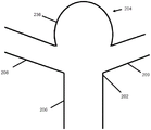
Fig. 20 shows a normal artery-capillary-vein intersection.
Fig. 21 shows an arteriovenous malformation (AVM) along the arterial-venous intersection.
Figure 22 shows a typical delivery step for plugging an AVM with a liquid plug.
Figure 23 illustrates a liquid emboli delivery procedure for occluding an AVM utilizing a microcatheter with a capture/sheath for delivering a liquid emboli from the venous side of the AVM according to one embodiment.
Figure 24 illustrates a liquid emboli delivery procedure for occluding an AVM using a first microcatheter to deliver a liquid emboli from the arterial side of the AVM and a second microcatheter having a capture/sheath for capturing emboli on the venous side of the AVM, according to one embodiment.
Figure 25 illustrates a catheter with a conical shaped trap, according to one embodiment.
Fig. 26 illustrates a catheter with an elongated shaped trap according to one embodiment.
Fig. 27 illustrates a catheter with a flared trap in accordance with one embodiment.
Fig. 28 illustrates a microcatheter according to one embodiment having a capture structure delivered through a larger guide or entry catheter.
FIG. 29 illustrates a microcatheter with a capture device in a partially delivered state through a larger guide or entry catheter, according to one embodiment.
FIG. 30 illustrates a microcatheter with a trap in a delivery state with an embolic sheath exiting the larger introducer or entry catheter, according to one embodiment.
FIG. 31 illustrates a separation system for separating a conduit according to one embodiment.
Detailed Description
Specific embodiments of the present invention will now be described with reference to the accompanying drawings. This invention may, however, be embodied in many different forms and should not be construed as limited to the embodiments set forth herein; rather, these embodiments are provided so that this disclosure will be thorough and complete, and will fully convey the scope of the invention to those skilled in the art. The terminology used in the detailed description of the embodiments illustrated in the accompanying drawings is not intended to be limiting of the invention. In the drawings, like numbering represents like elements.
Occlusion or embolization is a technique used to treat various intravascular conditions, such as aneurysms, atrial septal defects, patent foramen ovale, left atrial appendage occlusion, patent ductus arteriosus, fistulae, arteriovenous malformations (AVM), use of the fallopian tubes for disinfection, spermatic cord vein occlusion to test for sterile ductal occlusion, and occlusion in the peripheral vasculature. To facilitate occlusion, embolic material, such as embolic coils or meshes, are used to fill the treatment site (e.g., aneurysm), cut off blood flow to the site over time, promote clotting, and-in the case of aneurysms-help prevent rupture of the blood vessel that may lead to a stroke.
Liquid embolization is part of a novel embolization agent. Some liquid embolization embodiments are described in US9078950, which is incorporated herein by reference in its entirety. The liquid plug is a viscous biocompatible liquid. After exposure to blood or aqueous solutions, the liquid emboli precipitate. Many liquid plugs are mixed with dimethyl sulfoxide (DMSO) solvents to prevent premature clotting. Upon delivery through the delivery catheter and into the treatment site, the DMSO will rapidly diffuse out, causing the embolic material to precipitate from exposure to the blood. The precipitated emboli will occlude the treatment site and prevent blood flow into the target area. Liquid embolization is currently used to treat AVM, however, the use of liquid embolization to treat other vascular diseases such as aneurysms is difficult because the embolization may migrate to other areas of the vasculature prior to clotting, or may solidify and still migrate to other areas. Stents cannot be used to seal the aneurysm treatment area because the stent pore size is too large to prevent the egress of a liquid embolus, and the open ends of the stent provide an easy escape path for the embolus. Furthermore, even if liquid embolisms are used to treat AVM, there is still a risk of embolisms migrating.
The present invention solves the problems associated with migration of liquid emboli by providing a sealing device/system that adequately seals the target treatment site to prevent migration of embolic material-thereby allowing liquid emboli to be used in a variety of therapeutic procedures, for example as a treatment for aneurysms, which are currently unavailable due to the risk of emboli migration.
For purposes of illustration, the sealing devices, systems and methods will be described primarily in the treatment of aneurysms and AVMs. Although the following examples have particular utility when used with aneurysms and/or AVMs, they are not limited to this application and may be used to treat a variety of conditions/vascular malformations, including aneurysms, atrial septal defects, patent foramen ovale, left atrial appendage occlusion, patent ductus arteriosus, fistulae, arteriovenous malformations, fallopian tube occlusion or spermatic vein occlusion, for disinfection, and occlusion of the peripheral vascular system.
The following embodiments shown in fig. 1-9 and described below have particular utility in the treatment of aneurysms, including side wall aneurysms. Aneurysms occur when there are weakened regions along the vessel wall; when these aneurysms occur in the neurovascular system, the weakened area may develop into a prominent bulge that may ultimately lead to complications such as stroke. Lateral wall aneurysms occur along the side wall of a blood vessel. Liquid embolisms cannot generally be used to treat side wall aneurysms because of the high risk of migration of the liquid embolisms before or even after coagulation, where the liquid embolisms can migrate elsewhere leading to serious complications. The following embodiments are directed to sealing devices that are placed against an opening of an aneurysm to contain a liquid plug within the aneurysm.
Stents are sometimes used to treat aneurysms, where the stent is an open-ended tubular structure placed across the neck of the aneurysm. A flow diverting stent is a stent with a relatively small pore size that restricts blood flow to the aneurysm, closing off flow into the aneurysm over time. Secondary stents are also used and include holes and microcatheters are placed within the stent holes to deliver embolic coils into the aneurysm to occlude the aneurysm by a process known as stent secondary coil embolization. For various reasons, neither type of stent can be used with liquid embolic delivery. First, the proximal and distal open ends of the stent provide an easy escape path for liquid emboli that may infiltrate the stent, migration based on emboli formation increasing the risk of occlusion and stroke elsewhere in the vasculature. Second, the secondary scaffold includes large pores to accommodate microcatheters delivered through pores that are too large to prevent the passage of liquid embolic material.
Fig. 1 shows a sealing device 100 according to an embodiment, and in particular how the sealing device 100 will be positioned relative to an aneurysm 134, in this case a side wall aneurysm. A microcatheter 130 is positioned within the aneurysm to deliver the liquid embolus and a sealing device 100 is deployed to occlude the neck of the aneurysm. The sealing device 100 prevents migration of the delivered embolic material from the aneurysm 134. In one embodiment, the sealing device 100 generally has a cylindrical central portion 132c and tapered end portions 132a and 132 b. The tapered end section provides generally closed proximal and distal portions that help prevent migration of the liquid plug through the sealing device. Note that the term tapered refers to a reduction in diameter involving a particular direction. For the purposes of fig. 1, the particular shape shown is a tapered conical shape, but other tapered shapes are possible. The cylindrical central portion 132c can be considered to represent the working length of the device because, as shown in fig. 1, this portion will be located in the vessel above the neck of the aneurysm to help seal the neck of the aneurysm and prevent emboli from exiting the aneurysm.
The sealing device 100 is expandable, taking a collapsed shape during delivery through a catheter, and taking an expanded shape once delivered from the catheter. In this manner, the sealing device 100 may be considered an inflatable structure. The seal 100 includes a core wire 118 spanning the seal, as will be described in more detail below. The core-wire 118 is used to manipulate the shape of the sealing device 100 such that retracting the core-wire causes the sealing device 100 to radially expand and thereby help seal the treatment area. In this manner, the core-wire 118 may be considered a controller, and more specifically an expandable structure controller, wherein the core-wire may be used to control the shape of the expandable structure sealing device so as to allow the sealing device to assume an optimal shape to seal the treatment area and prevent the expulsion of liquid emboli from the vascular treatment site.
As previously mentioned, several types of liquid emboli are delivered with DMSO to prevent premature settling and clotting of the liquid emboli. Once exposed to blood, the liquid plug solidifies and the DMSO delivered with the liquid plug dissipates through the blood stream. The sealing device 100 acts as an inhibitor to help retain the liquid emboli in the aneurysm 134 and prevent migration of the liquid emboli elsewhere in the vasculature-for example, where the liquid emboli do not immediately settle and a portion of them may migrate out of the aneurysm before clotting, or where a portion of the settled liquid emboli may migrate out of the aneurysm.
In one embodiment, the sealing device 110 includes two layers, an inner layer 112a and an outer layer 114a, as shown in FIG. 2. In one embodiment, both the inner and outer layers are a mesh of metal wires. The wire mesh may include some nitinol and some radiopaque (e.g., tantalum, platinum, gold) wires, the inclusion of which would facilitate visualization. Alternatively, the lead may include a nitinol core with a radiopaque outer portion, or a radiopaque core with a nitinol outer portion. Alternatively, one of the mesh layers may include only nitinol wires, while the other mesh layer includes nitinol and radiopaque wires. In one embodiment, the inner layer 112a web and/or the outer layer 114a web may be comprised of Drawn Filled Tubes (DFT). DFT utilizes an inner core material surrounded by an outer sheath and is described in US7420124, the entire contents of which are incorporated herein by reference. The inner core may comprise one or more wire elements. By using different materials for the inner and outer sheaths, different material properties can be used to create the mesh. In one embodiment, a DFT with a platinum inner core and a nitinol outer sheath is used. The platinum inner core will increase radiopacity and aid in visualization of the device, while the nitinol outer sheath will provide good shape memory retention. The sealing device should have a large amount of shape memory, which the nitinol wire should have due to its strong shape memory properties. Known heat treatments for imparting shape memory, such as heat treatment on a mandrel shaped in the shape of a seal, may be used to impart the shape memory. Shape memory will mean that the sealing device 110 can assume a collapsed shape when housed within a microcatheter and then assume an expanded shape when released from the microcatheter due to the imparted shape memory. Thus, the sealing device may be considered an expandable structure, assuming a collapsed configuration when housed in a microcatheter, and an expanded configuration when released from the microcatheter.
In one embodiment, the inner layer 112a and the outer layer 114a are joined together. Mechanical connectors may be selectively placed over the entire length of the two layers to connect the two layers to each other. Alternatively, two layers of braided wire may be woven in an alternating pattern (e.g., under the bottom layer, over the top layer, etc.) to bond the layers together. In another embodiment, no connecting means is used between the layers-instead, each layer is formed of a shape memory material, and the built-in shape memory of the layers will allow each layer to expand once the sealing means is pushed out of the delivery catheter. The amount of built-in shape memory and the size of the blood vessels will inherently control the expansion of the two layers. It is known that heat treatment is used to impart shape memory, for example heat treatment on a mandrel shaped to the shape of the seal, may be used to impart this shape memory. Nitinol has particularly good shape memory qualities, so these layers may include at least some nitinol wires in the mesh to impart strong shape memory within the layers of the sealing device.
In a preferred embodiment, the inner layer 112a includes a denser mesh than the outer layer 114 a. Where a sealing device is used to retain the liquid embolic material delivered through the microcatheter 130 (as shown in fig. 1), the looser outer layer may allow some liquid emboli to pass through, but the denser inner mesh will capture the liquid emboli and prevent it from permeating through the inner mesh. This embodiment would be made by braiding a dense mesh using a mandrel and braiding a looser outer mesh using a mandrel. A looser outer mesh will be placed over a denser inner mesh. Optional accessories may then be used to join the layers, as described above. Because the sealing device need not accommodate a microcatheter, the inner layer 112a can be particularly dense to help prevent liquid emboli from passing through the inner layer and past the sealing device. As a failsafe, the tapered proximal and distal ends 132a, 132b of the sealing device provide a capture structure to capture any displaced liquid emboli.
In one embodiment, the looser outer layer comprises the length of the device and the denser inner layer is located only within the middle portion of the device. As shown in fig. 1, the intermediate portion 132b is against the entrance of the aneurysm, so the denser innerbraid of the device will align with the neck of the aneurysm and capture any loose or migrating emboli from the aneurysm. At the same time, the proximal and distal ends 132a, 132b of the device include only a looser outer mesh-rather than a tighter inner mesh-to enable blood and DMSO to flow undisturbed through these regions of the sealing device.
In another embodiment, a looser outer layer is used along the entire length of the device, and a dense inner layer is used for the middle 132C and distal 132B portions of the device. This may be preferred to help ensure that the liquid plug cannot migrate distally-because if the plug were to penetrate the inner layer, the dense distal end of the device would act like a trap. Since these devices are typically placed in the direction of blood flow, it is envisioned that blood flows from left to right and that the devices are placed so that the proximal end 132A is on the left and the distal end 132B is on the right. Since blood flows toward the "right" or "distal", it is preferable to have a trap on the distal or "right" side, as emboli can migrate downstream. In this embodiment, any liquid embolism that passes through the dense inner layer 112A of the intermediate portion 132C of the device will encounter the other dense inner layer 112A and a looser outer layer at the distal tapered region 132B. Even without the use of an inner layer on the distal tapered portion 132B of the device, the device can be easily constructed so that the distal tapered portion 132B is denser than the rest of the device-in other words, the outer layer 114A can be designed so that the outer layer at the distal tapered portion 132B is smaller than the pores of the outer layer in the middle portion 132C of the device.
In one embodiment, a denser interior web will prevent liquid embolic agent from entering, entrapping the liquid embolic between the inner and outer layers and forming a thin film between the two layers, which will allow the inner layer to shrink to aid withdrawal. Since DMSO is less viscous than the pre-precipitated liquid plug (and of course less viscous than the solidified or precipitated liquid plug), the denser distal tapered tip 132b should not affect the ability of DMSO and blood to flow through the area, as DMSO and blood are substantially less viscous than the liquid plug.
Other embodiments may utilize additional layers, such as three or more layers, where the grid density distribution of each layer may be different from the other layers. Other embodiments may use a sealing device that includes a polymer rather than a metal mesh structure. Other embodiments may utilize a combination of polymer and metal mesh to create the sealing device. Other embodiments may utilize a solid multilayer tubular structure that is laser cut to create holes in each layer. Other embodiments may utilize a stent as the inner layer, with a mesh having tapered proximal and distal sections placed over the stent to form a multi-layered structure.
In one embodiment, the cylindrical mid portion/working length portion of the device 132c may utilize a radiopaque member to aid visualization so the user can know the working length of the device relative to the location of the aneurysm. In one example, radiopaque marker coils or marker bands made of platinum, tantalum or gold may be selectively placed in the portion 132c of the device, which is thus particularly visible.
The sealing device includes a distal marker 116 shown in fig. 1 and 3-4 that is a radiopaque marker band that includes a radiopaque substance, such as gold, tantalum, platinum or palladium, that may be used for the crimped distal end of the outer mesh. Marker bands (not shown) may also be used at the proximal end of the device to crimp the proximal end of the outer mesh. The marker band includes a lumen; thus, the marker band may be considered a hollow cylinder or tube. Radiopaque markers may be used for imaging purposes to visualize the end of the device to aid in placement of the sealing device relative to the vascular condition. The core wire 118 spans the length of the device and also spans a hypotube delivery pusher 122, which hypotube delivery pusher 122 is proximally connected to the sealing device 110, the sealing device 110 being used to deliver (push/pull) the sealing device 110 through a catheter as shown in fig. 3-4. Core wire 118 passes through the marker band lumen. The core wire 118 may be made from a variety of materials, such as a metal (e.g., nitinol or stainless steel) wire or hypotube; alternatively, radiopaque substances such as tantalum, platinum, gold or tungsten may be used. In one embodiment, core wire 118 is made of a nitinol wire that is wrapped with a radiopaque coil to aid in visualization of the core wire. Delivery systems and methods of delivery using the core wire 118 will be discussed in more detail later.
Figures 3-4 illustrate a delivery system for a sealing device according to one embodiment. The sealing device 110 is connected to the distal end of the hypotube pusher 122. The user controls the pusher from the proximal end of the system to push and pull the hypotube 122 and attached sealing device 110 through the microcatheter 128 and through the blood vessel. A hypotube propeller is a tube and includes an internal channel or lumen. A core wire 118 is located within the channel and extends from the proximal end to the system where it is manipulated by the user, similar to a guidewire to track a guidewire and catheter through the vasculature, to the distal end of the system, distal of the sealing device. The proximal portion of the sealing device 110 is secured to the distal end of the hypotube 122. In one example, the proximal portion of the sealing device 110 is secured to the interior of the hypotube at location 124 by welding, adhesive, or similar means-although the proximal end of the sealing device 110 may also be secured to the outside of the hypotube at location 124. In one embodiment, there is no separation means for separating the sealing means from the hypotube. Since the sealing device is only used to prevent emboli from migrating from the aneurysm, once a liquid emboli is injected into the aneurysm and the emboli settles to occlude the aneurysm, the sealing device is removed from the vasculature. This may be accomplished by proximally retracting the hypotube pusher through the microcatheter 128, the microcatheter 128 also serving to deliver the sealing device. However, in alternative embodiments, it would be easy to introduce a separation system at the distal portion of the hypotube pusher to separate the sealing means — electrolytic, mechanical or thermal means could be used. In one example, there is a sacrificial element (e.g., at location 124 of fig. 3-4) between the sealing device and the hypotube that is thermally, electrolytically, or mechanically degraded to separate the sealing device. US20100269204, US20110301686, US20150289879 all describe thermal separation systems and are incorporated herein by reference in their entirety.
Fig. 5-6 illustrate two embodiments of the core wire 118 that span the length of the seal. Fig. 5 shows core wire 118 terminating in a distal coiled tip 120 that passes through the lumen of marker 116 and is distal to marker 116. The coiled tip comprises a coil; the coil shape is useful because if the distal tip impacts the vessel, the coiled tip allows some flexibility, which reduces the likelihood of the tip becoming stuck or penetrating the vessel wall. Fig. 6 shows the core wire 118 finally formed in the bent tip 120. The bent tip 120 is more ductile than the rest of the core wire and is intended to be bent in any direction. The user will pre-shape the distal tip by physically bending the distal tip or use a mandrel or tool to bend the distal tip in a particular direction. This curved shape is desirable so that if the guidewire is passed through the vasculature system and a bifurcation is present, the user can rotate the guidewire so that the curved tip is aligned with the correct vessel and can then push the guidewire through the appropriate vessel. This curved shape configuration, known in the art as a J-shape, if often used on a guidewire to help track the guidewire through tortuous anatomy, particularly at the bifurcation where the user must be able to select a particular vessel where the user will rotate or steer the guidewire into the desired vessel, and then continue to track the guidewire.
Typically, to access a vascular treatment site, a guidewire is first introduced into the vasculature and a large lumen catheter or access catheter is tracked over the guidewire to access the treatment site. The guide or access catheter provides an access path for a smaller microcatheter used to deliver a medical device or therapeutic material to a target area. The guidewire is a thin, navigable wire used only to access the target area and withdrawn once the target area is accessed. The inclusion of a core wire 118 spanning the seal will allow the core wire to act essentially like a guidewire and serve to track the catheter to the treatment site in a manner now to be described.
In one embodiment, the core-wire 118 and the core-wire distal tip 120 (see fig. 3-6) are free to move such that the core-wire 118 is not secured to anything and is free to move past the sealing device 110 and can even be completely removed by pulling on the core-wire 118, retracting it past the sealing device 110, and if desired, completely exiting the vasculature system by completely retracting the core-wire. In practice, this means that the lumen within the marker band 116 will be larger than the core wire 118 diameter and the core wire distal tip 120 diameter. The core-wire 118 may be used as a guidewire in that the core-wire 118 may be pushed distally away from the sealing device 110 and then used to track the sealing device and the catheter 128.
In another embodiment, the core-wire 118 is free to move distally but the distal tip 120 is larger than the marker band 116 lumen such that the distal tip 120 cannot be retracted through the sealing device 110. In practice, this means that the core wire distal section 120 is thicker than the rest of the core wire 118 and also is more luminal than the distal marker 116, thus contacting the distal marker 116 when retracted, limiting the amount of proximal movement of the core wire. Allowing some free distal movement of the core wire distal portion 120 will allow the configuration described above, where the core wire 118 can function like a guidewire and the core wire 118 can be used to track the sealing device 110 and microcatheter 128. Since the core-wire 118 is distally pushable, the user can simply push the core-wire 118 such that the distal tip 120 of the core-wire is well beyond the distal end of the sealing device 110 and well beyond the distal end of the catheter 124, the sealing device 110 being delivered therethrough. The sealing device 110 and catheter 124 may then be tracked over the core-wire 118. Retracting core wire 118 will cause core wire distal tip 120 to contact marker band 116, and applying sufficient retraction force on core wire 118 will cause sealing device 110 to expand and longitudinally contract radially due to the force exerted by distal tip 120 on marker band 116 and sealing device 110. The ability to control the radial shape of the sealing device in this manner will be appreciated later.
In another embodiment, the core wire distal tip 120 is not freely movable and assumes a fixed position. In one embodiment, the core-wire distal tip 120 is in a fixed position distal to the sealing device and the sealing device because it contracts and expands (e.g., during delivery), floatable on the fixed core-wire — such that the sealing device can be pushed through the fixed core-wire by the pusher 122. In one embodiment, a fastening mechanism, such as a collet, can be used to selectively lock the core-wire 118 in a fixed position — the collet will be in a proximal position such that a user can tighten the collet to lock the core-wire 118 or loosen the collet to move the core-wire 118. In one embodiment, the fixation position is achieved by securing the core wire 118 or core wire distal tip 120 directly to the distal marker 116. Core wire 118 is fixed and cannot move freely; this may be done by welding or adhesive. In one example, core wire 118 is welded or adhesively secured to the inside or outside of marker band 116. In another example, the core wire distal tip 120 is thicker than the remainder of the core wire 118, and the distal tip 120 is mechanically secured to the distal marker band 116. (one advantage of the system of securing the core wire to the distal marker 116 is that pulling the core wire 118 will pull the distal marker 116 proximally due to the core wire and marker connection, thereby radially expanding the shape of the sealing device because the sealing device is connected to the hypotube at one end and to the distal marker and core wire at the other end.
Referring to fig. 1, a microcatheter 130 for delivering a liquid embolus is placed within an aneurysm 134, followed by placement of a sealing device 100 to seal the aneurysm. The sealing device is delivered through a separate microcatheter 128 as shown in figures 3-4. Because multiple microcatheters are required (one for delivering the sealing device and another for delivering the liquid embolus), delivery of two separate microcatheters can be a problem because time is required to track the two separate microcatheters through the vasculature. In one embodiment, microcatheters 128 and 130 are both placed through a larger lumen guide or access catheter 126 as shown in FIG. 7. This configuration can be achieved in a number of different ways. For example, the larger delivery catheter 126 may include two lumens, and these separate lumens provide access to the microcatheters 128, 130. Alternatively, a larger delivery catheter has a single lumen and both microcatheters 128,130 are placed within the lumen. Alternatively, the larger delivery catheter 126 contains two lumens, and one of these lumens is used to deliver the embolus, while the other lumen is used to deliver the sealing device (essentially, the open lumen would itself act like a microcatheter). To illustrate, the guide or entry catheter 126 may be 6 or 7 French size (about 2-2 and 1/3mm outer diameter), while the microcatheter 128,130 is 2 or 3 French size (about 2/3-1mm outer diameter). For the inner diameter illustration, microcatheters 128 and 130 can have inner diameters of 0.017, 0.021 or 0.027 inches. These dimensions are for illustration only, and the dimensions of the microcatheter and delivery catheter may be sized or dimensioned as desired.
A separate guidewire may be used to navigate the guide/entry catheter 126 near the target treatment site (e.g., the guidewire may be placed within one lumen and then retracted once inside the treatment site). Alternatively, the core-wire 118 used with the sealing device 110 can be used as a guidewire as discussed in previous embodiments, wherein the core-wire 118 has a degree of distal freedom of movement such that the core-wire distal tip 120 can be advanced and the sealing device/system can be advanced through the core-wire.
The sealing device 110 is delivered through the microcatheter 128 and the sealing device is placed distal to the hypotube pusher as shown in figures 3-4. When the guide or access catheter 126 is tracked near the target treatment site (e.g., near the aneurysm), the microcatheter 130 for delivering the emboli to the aneurysm is first advanced to be within the aneurysm 134 (or, alternatively, the guide/access catheter 126 is retracted to expose the microcatheter 130), as shown in fig. 1. The microcatheter 128 is then also advanced out of the delivery catheter (or, alternatively, the guide/access catheter 126 is retracted to expose the microcatheter 128). The hypotube pusher 122 is then pushed (or the microcatheter 128 retracted) causing the sealing device 110 to be released from the microcatheter 128. The sealing device 110 is suitably placed under the neck of the aneurysm to seal the aneurysm. The placement of the sealing device 110 should be similar to the configuration shown in fig. 1, wherein the cylindrical middle portion 132c of the sealing device 100 seals the neck of the aneurysm 134 and the microcatheter 130 is secured to the sealing device 100. One potential complication of microcatheters being fixed 130 to the sealing device 100 is that there is still a small gap between the microcatheter 130 and the sealing device 100, which results in the sealing device 100 not being able to completely seal the area under the neck of the aneurysm 134. This small gap will be primarily towards the proximal portion of the sealing device, as the microcatheter will primarily contact the sealing device on the proximal portion of the sealing device (as shown in fig. 1), and the self-expanding nature of the sealing device will tend to cover some of the open distal interface between the microcatheter 130 and the sealing device. This small gap may provide a escape path for emboli that may migrate out of the aneurysm without becoming trapped by the sealing device 100. The earlier embodiments discuss a concept wherein the core wire 118 is fixed to the distal marker 116, another concept is that the core wire distal tip 120 is thicker than the marker band 116 and cannot be retracted past the marker band 116, and how the core wire is pulled to radially expand the sealing means. The system can be used to radially expand the sealing device so that there is no gap between the aneurysm and the sealing device that could otherwise allow the embolus to seep out of the aneurysm and not become lodged by the sealing device. Thus, the user may simply retract the wire 118 (see fig. 1) to inflate the sealing device and seal any gaps between the microcatheter 130 and the area under the aneurysm. Since the wire 118 may be used to manipulate and control the shape of the inflatable sealing device, the wire 118 may be considered an inflatable structure controller/control mechanism. Note, however, that even if there is a small gap, blood flow proceeds in the downstream direction (i.e., left to right in fig. 1), and so does the inclusion of a tight distal mesh/capture structure along the distal section 132b, capturing the embolus as it leaks. In addition, the microcatheter 130 itself will fill most of the proximal interstitial space.
Once the liquid embolism begins to fill the aneurysm, it may migrate through the neck of the aneurysm before clotting-or portions of the liquid embolism may clot but still detach from the larger embolic material. Some of the plug may pass over the more permeable outer layer (114a, see fig. 2) of the sealing device 110, however the plug will be captured by the less permeable inner layer of the sealing device. Ideally, there is a small gap between the inner and outer layers of the sealing device-this small gap provides a capture area for the liquid plug so that the plug is captured between the gaps defined by the outer 114a and inner 112a sealing layers. As mentioned before, in case a connection device is used between two layers, the number of connection points or the tightness of the wire wound on the layers will affect the size of the gap between the two layers. More connection points, or tighter wires around the layers, will result in smaller gaps; and fewer connection points or wider wires running around the layers will result in a larger gap. These variables can be adjusted to control the size of the gap between the inner and outer layers. A plug of liquid will be trapped between the two layers forming a thin film of precipitated solidified material. In the case of using a single layer device (e.g., a single layer stent) as an embolic stent, the large pore size will allow the liquid emboli to freely migrate through the device, which may introduce a risk of stroke elsewhere in the vasculature. On the other hand, a single layer device with small pores will result in liquid emboli being trapped outside the stent, which will make re-nesting of the device very difficult, as adhering a thick layer of emboli to the device effectively increases the overall diameter of the device. In contrast, as contemplated by several embodiments of the present invention, a multi-layered sealing device 110 comprising a tighter inner layer of mesh and a looser outer layer of mesh will allow for gaps or pockets between the tighter inner layer and the looser outer layer to hold a settled or solidified liquid plug-this configuration is shown in fig. 9, where a trapped plug 200 is located between the looser outer layer 114a and the tighter inner layer 112 a. The sealing device can still be withdrawn because the inner layer can still be collapsed when the catheter is re-inserted, because there is nothing effective under this inner layer-the act of collapsing the inner layer will help force the outer layer and the embolic pocket to collapse as well, allowing the sealing device to be withdrawn from the vasculature after the liquid embolus has sufficiently occluded the aneurysm. In one example, after an embolic delivery procedure, the proximal end of the sealing device is stapled to a microcatheter 128, the microcatheter 128 is used to deliver the sealing device, and the sealing device is retracted into the guide catheter 126, which guide catheter 126 is used to remove the device from the vasculature.
Another embodiment may use an inner balloon and an outer mesh as the sealing means. A microcatheter for delivering the sealing device will contain an inflation lumen to inflate the balloon once the sealing device is placed. The outer mesh may still be self-expanding, or balloon inflation may open the support mesh. Alternative embodiments may utilize multiple mesh layers and an inner balloon, or the embodiment of fig. 1, wherein an inflatable inner balloon is included within the multiple mesh layers. The embolus may pass over the outer mesh layer but may be trapped on the balloon.
In one example, the sealing device has an inner layer and an outer layer. The inner layer has a diameter of about 4-5 mm and the outer layer has a diameter of about 4.5-6 mm. In one example, the inner layer has a diameter of about 4.2 millimeters and the outer layer has a diameter of about 4.7 millimeters. Note that the difference in diameter between the inner and outer layers provides the pockets or gaps discussed above in which any displaced liquid emboli may be trapped or captured. In one example, the inner and outer layers are constructed of wire mesh, wherein the wires have a diameter of about 0.0005-0.002 inches. The inner layer wire may have a different diameter than the outer layer wire, or the wire comprising both layers may have the same diameter. In one example, the sealing device is configured such that the inner layer pores are about 50-1000 microns, in one example 75-500 microns, in one example about 100-250 microns, and in one example about 100-150 microns. Larger pore sizes will allow blood and DSMO to pass while also increasing the likelihood of liquid emboli passing through, while smaller pore sizes are more likely to prevent flow of emboli, but extremely small pore sizes may prevent flow of blood and DMSO.
Various techniques may be used to manufacture the sealing device. For example, the sealing device may be braided on a mandrel, wherein the mandrel comprises two tapered ends to form the tapered proximal and distal section shapes shown in fig. 1. Alternatively, the sealing device is braided over the tubular mandrel and the deployment marker band is formed into a tapered shape on the proximal and distal ends. Note that as previously mentioned, the term tapered refers to a reduction in diameter that involves a particular direction. For the purposes of fig. 1, the particular shape shown is a conical taper, but other tapered shapes are possible as will be described.
Fig. 1 shows a sealing device having a conically tapered proximal 132a and distal 132b cross-sectional shape. The sealing device may take on a variety of shapes, including various proximal and distal section shapes. In one example, the proximal section 138a of the sealing device has a conical shape, while the distal section 138b of the sealing device may have a circular shape, as shown in fig. 8. Such a shape may be achieved, for example, by utilizing a mandrel having a rounded end section over which the distal section is braided. Alternatively, the proximal end of the sealing device may have a circular shape, while the distal end of the sealing device has a tapered shape. Alternatively, both the proximal and distal ends of the sealing device may have a rounded shape. This shape may be used to form a seal by using a mandrel with two rounded end sections.
The following embodiments shown in fig. 10-19 and described below have particular utility in the treatment of aneurysms, including bifurcated aneurysms. Bifurcated aneurysms occur in the region of vessel bifurcations. Vessel bifurcations are areas of high blood flow, and the large amount of pressure exerted on the vessel wall in the bifurcation area can lead to the formation of an aneurysm. Bifurcated aneurysms represent the vast majority of aneurysms in the neurovasculature, which if ruptured, may lead to complications such as stroke. Bifurcated aneurysms can be difficult to treat because the geometry of the vessel bifurcation area makes placement of a stent or other device difficult because the bifurcation area spans multiple vessels. Typically, two stents are placed across each other to cover both branches of the bifurcation, a procedure known as y-stenting. The aneurysm itself may fill the embolic coil, with a plurality of stents retaining the embolic coil. Alternatively, two shunt stents may be placed together to restrict blood flow to the aneurysm. Due to the time and expense associated with placing multiple stents, the double stent procedure is challenging and costly. Liquid embolization cannot generally be used to treat bifurcated aneurysms because of the high risk of liquid embolization migrating before or even after clotting, where the liquid embolization can migrate elsewhere resulting in serious complications. The following embodiments are directed to sealing devices that may be placed within or against the neck of a bifurcated aneurysm to facilitate use of a liquid embolization.
A bifurcated aneurysm 204 is shown in fig. 10. As shown, bifurcated aneurysm 204 occurs at a vessel bifurcation, where parent vessel 206 branches into vessels 208, 209.
Figure 11 illustrates an occluding device 210 used in a sealing device/system that is particularly beneficial in treating bifurcated aneurysms. In one embodiment, the occluding device 210 is formed of a plurality of braided metal wires. The lead may be made of nitinol, stainless steel and/or cobalt chromium alloy. Nitinol is a particularly preferred material because of its strong shape memory properties. Radiopaque wires (e.g., tantalum, platinum, palladium, and/or gold) may also be incorporated into the braided wire mesh to aid visibility. The occluding device 210 has a heat set shape wherein the guidewire comprising the occluding device 210 is heat set to a particular expanded shape such that the occluding device assumes the expanded shape when delivered from the catheter. Thus, the occluding device may be considered an expandable structure. The occluding device 210 comprises a distal portion 212 and a proximal portion 214 separated by a band 216. The band is placed over the braid and used to form a constriction in the occluding device, defining a distal portion 212 and a proximal portion 214. May be constructed of a metal (e.g., nitinol or stainless steel) tube or crimped. Alternatively, radiopaque marker bands (e.g., tantalum, platinum, palladium, gold) may be used to aid visualization. A distal coil 218 is attached to the end of the occluder. The coil 218 preferably has a shape memory coiled shape configured such that when the coil 218 contacts the wall of the vessel, the coil 218 will curl inward rather than stick to the wall. In one example, the coil 218 is made of nitinol or a radiopaque material such as platinum. When the occluding device 210 is placed in an aneurysm, the coil 218 is the first target to contact the dome of the aneurysm. The coil 218 contacts the dome of the aneurysm and serves as a base structure with the rest of the occluding device 210 open underneath it. The proximal portion of the occluding device 210 is connected to a pusher 230. The pusher tube is tubular and contains an open lumen.
The tension line 222 extends along the length of the occluding device 210 as shown in figure 12. The distal end of the tension wire 222 is connected to the distal coil 218. In one embodiment, the inner surface of the coil 218 includes a distal threaded interface. The end of the wire 222 may be screwed in by mechanical rotation. This mechanical connection can be achieved in several different ways. For example, the distal end of the tension wire 222 may include male threads and a portion of the lumen of the coil 218 may include a corresponding nut. Alternatively, the coil 218 is placed on a mating structure, and the mating structure includes a threaded interface to mate with a corresponding interface on the distal end of the tension wire 218. Other embodiments may forego the distal coil 218 and instead include only an interface structure, such as a cap, to which the tension wire may be mechanically connected (e.g., via the male/female thread rotation concept discussed above). The tension line 222 spans the length of the pusher 230. The pusher 230 is a tube and contains an open lumen spanning the length of the pusher that houses the tension wire 222, as shown in fig. 13-15. The tension wire 222 and pusher 230 are individually controlled and manipulated by the user from the proximal end of the system; the proximal end of the tensile strand 222 is located beyond the proximal end of the pusher 230 such that the tensile strand and the pusher are independently pushed/pulled. Pushing or pulling the pusher pushes or pulls the entire system and the way in which the push-pull tension wire manipulates the shape of the occluding device 210 will now be described. The distal portion of the tension wire 222 is connected to the coil 218, but this is the only portion of the tension wire 222 that is connected to anything. Thus, pushing the tension wire 222 will exert a force on the coil 218, thereby pushing the coil and attached occluding device 210, thereby elongating the occluding device 210 to assume the shape shown in figure 12. Pulling the tensioning wire 222 will exert a retraction force on the coil 219, pulling back the coil and attached occluding device 210 so that the occluding device 210 assumes the compressed shape shown in figure 11. Since the tension wire 222 may be used to manipulate and control the shape of the expandable occluding device 210, the wire 222 may be considered an expandable structure controller/control mechanism. The occluding device 210 may comprise folded layers wherein when the tensioning line is retracted or pulled, the occluding device 210 contracts and the layers fold over each other. The folded layers will allow for the use of a large amount of material on the occluding device, but the occluding device takes on a smaller profile when compressed, allowing for a significant difference between the compressed and elongated shape of the occluding device.
Fig. 13 shows the sealing system during delivery through the larger delivery catheter 232, including the occluder 210. In one example, the delivery catheter 232 is a 6 or 7 french guide or entry catheter and the pusher 230 is 2-3 french size-this would represent a relatively large system as embolic devices are typically delivered through 2 or 3 french size microcatheters. In another example, the delivery catheter 232 is a 2 or 3 french sized microcatheter and the pusher is 1-2 french sized to be contained within the microcatheter. The occluding device 210 is nested within the delivery catheter 232 and navigated or pushed through the delivery catheter 232 to the treatment site. Due to the restraining force provided by the delivery catheter 232, the occluding device 210 assumes an elongated configuration when placed within the delivery catheter, as shown in figure 13. The user pushes the pusher 230 to navigate the sealing system through the delivery catheter 232. The tension wire 222 may also push the pusher 230 alone as the pusher 230 is pushed during delivery to maintain tension on the occluding device and ease delivery by minimizing the portion of the occluding device 210 that contacts the inner wall of the delivery catheter 232 during delivery, thereby minimizing friction. There is a detachable connection 226 between the pusher 230 and the occluder 210 which can be detached to sever the occluder from the pusher as will be described in more detail later. Element 224 represents an attachment mechanism that connects the tension wire 222 to the distal coil 218.
Figures 14-15 show the occluding device 210 after being pushed out of the delivery catheter 232. Due to the increased heat-set shape imparted to the occluder, the occluder 210 will assume an expanded configuration after release from the delivery catheter 232. In fig. 14, the tensioning wire 222 is pulled to contract the shape of the occluding device 210, thereby enabling the occluding device to assume a longitudinally contracted radially expanded shape. The occluding device 210 is delivered to the target treatment site and then the tensioning wire 222 is pulled to contract the shape of the occluding device 210 to conform to the shape of the treatment area. When the shape of the occluding device 222 is properly configured for the treatment area, the tensioning wire 222 is withdrawn-in embodiments where the tensioning wire is a mechanical threaded connection, the tensioning wire may simply be unscrewed and then pulled out of the pusher tube 230-as is preferred, the tensioning wire may be pushed/pulled so that the proximal portion 224 of the occluding device 210 is as wide as possible to conform to the bottom portion of the aneurysm 236 while still fitting into the aneurysm. Since the occluding device proximal portion 224 is typically adjacent or near the neck of the aneurysm, it should be as wide as possible to prevent migration of the plug through this layer.
Once the wire is withdrawn, the pusher tube 230 may be used to deliver additional embolic agents, including liquid embolic agents and/or other agents including embolic coils or meshes. In fig. 17, a pusher tube 230 is used to deliver a liquid plug 234. It may be beneficial to remove the tensioning wire 222 from the pusher 230 prior to emboli delivery in order to maximize the luminal space for emboli delivery, however, if the tensioning wire 222 is narrow enough it may not be necessary to remove the tensioning wire 222 prior to emboli delivery. The liquid embolus is delivered to the target treatment site. A liquid plug delivered in liquid form will readily pass through the pores of the occluding device 210. The pores of the occluder 210 will also allow DMSO to diffuse out of the occluder as it diffuses from the liquid plug after delivery. The porous mesh occluder 210 will also allow blood to flow through when blood is displaced due to delivery of a liquid plug. When a liquid embolus is exposed to blood, the embolus begins to precipitate. As the plug settles, it becomes more viscous and can no longer pass through the bore of the occluder 210; the plug then solidifies and occludes the target space. Thus, the embolus is contained within the aneurysm/treatment site. In one embodiment, the occluding device 210 includes a polymer coating to further aid in plug retention; the polymer coating increases the thickness of the occluding device 210 and decreases the pore size, thus providing some additional advantages in terms of plug retention. The polymer coating may be applied at selective locations along the occluding device 210 such that there are still porous openings to allow blood and DMSO to diffuse through the occluding device 210. In one embodiment, the pores of the mesh of the proximal section 214 are smaller than the mesh of the distal section 212; this can be achieved by utilizing a smaller hole in the proximal section 214, which will ensure that a liquid embolism is less likely to pass through the proximal section 214 and penetrate beyond the aneurysm. In one embodiment, a polymeric coating may be used only along the proximal section web 214 to reduce the porosity of the region to help prevent emboli from passing through the region. In one example, the mesh sizes are configured such that they are about 50-1000 microns, in one example about 75-500, in one example about 100-250 microns, and in one example about 100-150 microns.
After the liquid plug 234 is delivered and deposited, the push tube 230 is withdrawn. Between the pusher 230 and the occluder 210 there is a detachment joint 226 which can be cut to detach the pusher from the occluder. Various types of separation systems may be used, such as mechanical, thermal or electrolytic systems. US8182506, US20060200192, US20100268204, US20110301686, US20150289879, US20151073772, US20150173773, all of which are incorporated herein by reference in their entirety, disclose various separation systems that may be used with the present concepts. The detachment joint 226 includes a detachable linkage, such as a detachable tether or degradable substance, that thermally, mechanically or electrolytically degrades to effect detachment of the occluding device. In one example, the user will activate a user interface (i.e., a button) to degrade a portion of the detachment joint to effect detachment between the pusher 230 and the occluding device 210.
Fig. 18-19 illustrate the treatment process within a bifurcated aneurysm 236. The sealing system is delivered to the bifurcated aneurysm 236 via a blood vessel 238. Due to the steerable shape of the occluding device 210, the occluding device is physically located within the vessel and subsequently prevents the delivered plug from oozing out.
In one embodiment, the distal portion 212 of the occluding device 210 is located within the aneurysm and the proximal section 214 of the occluding device 210 is located outside the aneurysm, the proximal section 214 essentially will act like a neck seal to ensure that the plug does not detach from the neck of the aneurysm. In another embodiment, the occluding device 210 is located entirely outside of the aneurysm, and the occluding device functions like a neck seal or hook flush with the neck of the aneurysm and prevents plug migration.
Arteriovenous malformations (AVMs) are abnormal connections formed between an artery and a vein. Arteries supply oxygen-enriched blood from the heart to various parts of the body, while veins carry oxygen-depleted blood to the heart. The capillaries usually connect arteries and veins. The AVM is typically formed as a wound connector, bypassing the normal capillary system. Vascular abnormalities of malformed blood vessels are commonly referred to as lesions. AVMs can form in many places but are usually formed in the brain and present a bleeding risk that can lead to a stroke. The AVM includes an arterial side (connecting artery) and a venous side (connecting vein) like a capillary.
Fig. 20 shows a normal artery-capillary-vein intersection, which includes an artery 310, a vein 312, and a capillary 314 connecting the artery and the vein. Figure 21 shows an AVM316, which is an abnormal connection between an artery and a vein that bypasses normal capillary structures. AVM is an unnatural connecting structure that interferes with the normal circulation pattern, drawing blood away from the capillaries. Over time, AVM can bleed, leading to various complications. Note that the AVM may take an extremely tortuous shape with many different connections, a relatively "simple" AVM shape being shown for ease of illustration.
Note that blood in the artery will flow in the direction of the AVM/capillary, while blood in the vein will carry blood away from the AVM/capillary. Thus, in fig. 20-22, blood flows generally from left to right, from artery to vein, as indicated by arrows 317 in fig. 21-24.
AVM can occur at various locations throughout the body, including neurovasculature and brain. Neurovascular AVM is particularly problematic and can lead to rupture leading to stroke. Some therapeutic approaches to treating AVM involve occluding the AVM with a liquid plug so that blood flow bypasses the AVM and normal circulation is restored. In a typical procedure, a microcatheter connected to a liquid embolus is traced through the arterial vasculature to the arterial side of the AVM near the lesion. The liquid plug is then injected through the microcatheter and into the AVM. The liquid emboli hardens or coagulates, preventing blood from passing through the AVM and restoring flow to the capillaries and normal circulation.
One problem with conventional liquid embolic delivery methods is that too much liquid emboli can be delivered and some emboli can migrate out of the AVM, or emboli can migrate before hardening and through the AVM and into the venous system. In the case of AVMs located in the neurovascular system and fluid embolization for treatment of AVMs, the neurovascular venous pathway enters the pulmonary system-so an embolism in the venous system may eventually enter the lungs, leading to serious complications. Clotting of the plug in the venous blood flow path may also close the natural outflow of blood, which may lead to AVM rupture. A typical procedure involves passing through arterial vasculature through the femoral artery and using a guidewire and a guide or access catheter tracked over the guidewire into the portion of the vasculature containing the AVM. The smaller microcatheter is then tracked to the actual treatment site. The proximal portion of the microcatheter is connected to a syringe containing a liquid embolus that is delivered through the microcatheter into the AVM. This conventional delivery method is illustrated in fig. 22, where a microcatheter 318 is passed through the arterial side 310 of the AVM 316. A microcatheter 318 is placed in/near the lesion of the AVM and a liquid plug 320 is delivered into the AVM. Since the liquid emboli are delivered from the arterial side of the AVM, the emboli are delivered in the direction of blood flow (see arrows 317 in fig. 22), which makes it more likely that emboli will be pushed out of the AVM and into the venous system with the direction of blood flow.
One method of addressing the embolic migration problem contemplated by the present invention involves delivering the emboli from the venous side 312 of the AVM316, as shown in fig. 23-rather than the typical procedure of delivering the emboli from the arterial side 310 shown in fig. 22. The femoral or jugular vein is used to access the venous vasculature, and the guidewire and guide catheter are tracked by the venous system to a location near the AVM 316. The microcatheter 318 is tracked through a guide or entry catheter to the venous side 312 of the AVM 316. The liquid embolus 320 is then passed through the microcatheter lumen and delivered into the AVM316 from a syringe connected to the microcatheter 318. Due to delivery from the venous side 312 of the AVM316, microcatheter placement and fluid embolization delivery will be against blood flow, with arterial-to-venous blood flow indicated by arrows 317 in fig. 23. Since the liquid embolus 320 is delivered against the blood flow, the liquid embolus does not infiltrate the arterial system through the AVM because the liquid embolus is more viscous than the blood. The relatively high viscosity of the liquid embolus as compared to blood makes it less likely that embolic reflux or reflux will occur even if the liquid embolus is against the native blood flow, however, the microcatheter includes a capture or sheath structure 322 to capture any emboli that have undergone reflux.
Another approach to addressing the embolic migration problem contemplated in the present invention involves delivering the emboli from the arterial side 310 of the AVM, but placing a trap or sheath on the venous side of the AVM to trap any migrating emboli, as shown in fig. 24. This would involve the use of two microcatheters — a first microcatheter 319a for delivering a liquid embolus is delivered to the arterial side 310 of the AVM316, while a second microcatheter 319b with a latch 322 is delivered to the venous side 312. The AVM316 liquid embolus is injected through a microcatheter 319a placed on the arterial side of the AVM, in the direction of blood flow as indicated by arrow 317-this is similar to a conventional delivery procedure. However, unlike typical delivery procedures, the microcatheter 319b and the trap/sheath 322 are placed on the venous side of the AVM and will trap any migrating emboli. In one example, the vascular access is tracked to the arterial side 310 of the AVM316 by a guide or entry catheter through the femoral artery and microcatheter 319A. Vascular access to the microcatheter 319B is taken through the femoral artery or jugular vein, with the microcatheter 319B being tracked through a catheter or access catheter to the venous side 312 of the AVM 316.
Another embodiment for addressing the issue of emboli migration is conceptually similar to the embodiment of FIG. 24, except that both microcatheters 319a and 319b will deliver a liquid emboli. Both microcatheters 319a and 319b are connected to a syringe containing a liquid embolus, and the embolus will be delivered into the AVM316 from opposite sides of the AVM316 through both microcatheters. In this embodiment, plug occlusion from one side is not relied upon. The AVM will be plugged from both sides, which will provide some advantages of ensuring successful plugging of the AVM. The presence of the capture or sheath structure 322 on the microcatheter 319b will ensure that any emboli that might migrate from the AVM316 into the venous system will be captured by the sheath 322.
Fig. 23 shows a microcatheter 318 with a latch or sheath 322. The microcatheter has a lumen for injection/delivery of embolic material. The microcatheter lumen may house a guidewire that allows navigation and guidance of the microcatheter so that the microcatheter can be tracked over the guidewire and through a guide or entry catheter. In one embodiment, the latch or sheath 322 comprises a wire mesh. The mesh may comprise nitinol wires woven together to form a sheath-nitinol is a material with particularly good shape memory retention characteristics. Alternatively, radiopaque (i.e., gold, platinum, tantalum, palladium) wires may be added with the nitinol wires in the mesh to aid visualization. The jacket 322 may also comprise various materials, such as cobalt-chromium, stainless steel, polymers. The sheath 322 is preferably constructed of a biocompatible material because the sheath will be deployed within the vasculature. The mesh preferably has smaller pores; the pore size should be large enough to allow relatively unimpeded blood and DMSO flow, but small enough to prevent the passage of heavier and more viscous embolic material, particularly when the liquid embolus begins to become thicker and coagulates upon exposure to blood. In some examples, the pore size may be about 50-1000 microns, about 75-500 microns, about 100-250 microns, or about 100-150 microns. The sheath may be considered a tightly woven mesh/basket for capturing embolic material. The sheath will capture the liquid embolic agent as it precipitates while allowing the flowing blood to still pass through the sheath until the AVM is fully occluded — once the AVM is fully occluded, little or no blood flow through the AVM will result due to the occlusion effect of the coagulomb. In one example, the user would inject a liquid embolus until the embolus fills the AVM lesion through the arterial side to penetrate the arterial feeder vessel to cut off blood flow into the AVM, thereby eliminating any blood flow path into the AVM. Once the AVM is completely occluded, the risk of AVM rupture is low because there is no longer any blood flow into the AVM. In addition, once the liquid plug settles or solidifies, the plug should remain in place as it will be a uniform solidified mass that plugs the AVM.
FIGS. 25-27 illustrate a microcatheter 318 and locking/sheath 322a-322c, wherein the sheath has many different shapes-the sheath can assume a variety of shapes, including parabolic, linear, and conical profiles as shown in the figures. The shape may take a shape similar to a satellite dish (parabolic) or a noise projecting loudspeaker (linear/conical profile). Note that the side profile of the sheath is shown and the sheath surrounds the distal portion of the catheter, so the sheath is disposed radially around the catheter. Fig. 25 shows a frusto-conical sheath shape 322a in which the distal portion of the sheath expands radially outward like a conical base, similar to a loudspeaker. In fig. 26, the sheath 322b has a more elongated shape with the proximal portion of the sheath tapering outwardly and the distal section of the sheath having a relatively uniform shape and/or diameter. In fig. 27, the sheath 322c takes a shape closer to the horn. The sheath may have one or more layers-for example, the mesh may be folded back on itself, or folded under itself, to create a multi-layer mesh. Alternatively, multiple meshes may be overlapped and connected together to create a multi-layered mesh. The sheath may be located around the distal tip of the catheter, or slightly closer around the distal tip-but should still be facing the distal region of the catheter. The distal end of the sheath may be flush with, located past, or proximal to the distal tip of the catheter. Note that the sheath shape is shown and described for ease of illustration, but in practice many different shapes may be used for the sheath 322.
As previously described, the microcatheter 318 is delivered through a larger access or guide catheter. A larger entry/guide catheter will provide a restraining force to collapse the sheath during delivery. When the microcatheter 318 is released from the delivery catheter, the sheath will assume its natural deployed shape. Preferably, the sheath is constructed of a material having good shape memory, so that this natural deployed shape is disposed within the shape memory of the sheath. As noted above, nitinol has good shape memory properties-in one example, the mesh sheath 322 comprises nitinol that is heated to its expanded shape. Once the sheath 322 is released from the larger entry/guide catheter, the sheath will naturally assume its expanded shape due to the imparted shape memory. In one embodiment, the sheath configuration in the delivery and expanded states is similar-i.e., in the delivery state with the microcatheter 318 and sheath 322 contained within the larger guide catheter, the sheath simply assumes a compressed position in which it is pressed against the microcatheter. Once the sheath 322 is unconstrained by the introducer/access catheter, the sheath 322 expands outwardly.
In an alternative embodiment shown in fig. 28-30, the sheath 322 assumes a first, inverted configuration while nested within a larger entry/guide catheter 334 and assumes a second, deployed position upon release from the entry/guide catheter 334. Figure 28 shows a microcatheter 318 with a sheath 322 attached to the distal portion of the microcatheter 318 within a larger entry/guide catheter 334. The sheath 322 is connected to the microcatheter 318 at location 336. Portion 338 of the sheath 322 represents the distal portion of the sheath 322 when the sheath is fully deployed and without the larger guide catheter 334, as shown in fig. 30. When the microcatheter 318 is received within the guide catheter 334, the section 338 of the sheath 322 is folded back and proximal with respect to the section 3 section where the sheath 322 is attached to the microcatheter 318. Fig. 29 shows an intermediate position in which a portion of the microcatheter 318 exits the guide catheter 334, but the sheath is still in an inverted state, the sheath assumes an inverted configuration since the microcatheter 318 has not been advanced to the point where the sheath itself exits the larger guide catheter 334, the microcatheter 318 will be preloaded within the guide catheter 334, or the user can load the microcatheter 318 through the guide catheter 334, but the user will ensure that the sheath is inverted during placement.
In one embodiment, the sheath 322 is not detachable from the microcatheter 318. In this embodiment, a liquid plug would be delivered (as shown in fig. 23). After the emboli are delivered through the microcatheter 318 and coagulated, and any regurgitated emboli are captured by the sheath 322, the microcatheter 318 with integral sheath 322 is withdrawn. However, it is generally preferred to have a detachable sheath, so the user can choose to leave the sheath 322 in place to catch any emboli that may be removed in the future-or to address situations where an emboli in the sheath is present that make it difficult to withdraw the sheath 322.
In one embodiment, the sheath 322 is detachable from the microcatheter 318. If detached, the sheath will remain in the vasculature as an implant and the catheter will be withdrawn. However, the user may decide not to remove the sheath — for example, if it is believed that the embolus has coagulated and does not migrate through the venous system, or that there is no embolus that has regurgitated and the sheath is relatively free of emboli. The emboli will be delivered through the microcatheter 318 and any migrating or regurgitated emboli will be captured in the sheath 322. The user may detach the sheath 322 and withdraw the microcatheter 318 — leaving the sheath in place in the event of any additional embolic migration or reflux. Thus, the sheath 322 will remain a permanent implant. Alternatively, the user may decide not to remove the sheath 322, but to retract the microcatheter 318 with the attached sheath 322. In one example, the user can retract the microcatheter 318 and sheath 322 through the catheter 334; in another example, a user may retract a portion of the microcatheter 318 through the guide catheter 334, but leave the sheath 322 distal of the guide catheter and in this manner retract the system through the vasculature. The sheath 322 is preferably made of a biocompatible material, such as the nitinol wire discussed above, because if separated, the sheath would become an implant. However, the sheath may also be detached and subsequently retrieved.
Fig. 31 shows a microcatheter 318, a sheath 322 and a detachment system for detaching the sheath 322 from the microcatheter 318. The sheath 322 is preferably disposed near the distal tip of the microcatheter 318. As previously described, the distal portion of the sheath 322 may be flush with the distal tip of the microcatheter 318, located beyond the distal tip of the microcatheter 318, or located proximal to the distal tip of the microcatheter 318. The electrolytic separation system is shown in FIG. 31. The microcatheter 318 includes a metal coil 332 positioned around the outer diameter of the microcatheter or disposed within the wall of the microcatheter 318. The metal coil may be made of many materials, such as stainless steel. The coil is used to provide structural strength to the catheter and will also carry current through the coil. The voltage source 330 is disposed proximal to the system and provides a positive current source, in one example, a DC power source. The adhesive pad may be adhered to the patient so that the patient himself (via the blood stream) is grounded. The catheter metal coil 332 terminates in a metal (i.e., stainless steel) marker tube insert 326, which marker tube insert 326 is connected to the coil 332. The sheath 322 is connected to a fusion joint 324, and the fusion joint 324 may be a polymer or metal element. A fusion splice connects the sheath 322 to the microcatheter 318 and can be crimped over the sheath 322. The marker tube insert 326 contains small laser cut grooves 328 that provide thinned weakened areas in the insert that accelerate the electrolytic separation of the sheath 322 from the microcatheter 318. Once the separation sequence begins, any distal side of the groove 328 should fall out and remain in the bloodstream with the sheath 322. Electrolytic separation occurs when current from the power source passes through the coil 332, through the marker tube insert 326, through the patient's blood stream, where the patient's blood provides the ionized fluid medium for electrolytic separation. When the separation sequence begins, the microcatheter 318 and sheath 322 are already in the vessel and therefore they have been exposed to blood. The user will interact with the voltage source 330-in one example, there may be a button or some user interface to detach the sheath 322 if desired.
Alternate embodiments may utilize other separation systems including mechanical, thermal or other electrolysis concepts. For example, a mechanical system may be used in which the screw may be rotated, which will loosen the distal sheath connection to achieve sheath separation. Alternatively, a thermal detachment system may be used in which the catheter structure coil 332 is connected to a heater coil located above the tether and which cuts the tether when heated to detach the sheath. Alternatively, a thermal separation system may be used in which the adhesive is heated and melted to effect separation of the jacket. Alternatively, the structural coil 332 may be attached to a capsule element, and the capsule element itself would contain a detachable tether or electrolytically degradable link within the capsule to detach the sheath. US8182506, US20060200192, US20100268204, US20110301686, US20150289879, US20151073772, US20150173773, all of which are incorporated herein by reference in their entirety, disclose various separation systems that may be used with the present concepts. Various embodiments may also utilize a proximal battery having positive and negative terminals, and a catheter structure coil or lead from the battery to the shield 322 to the degradable linkage, wherein degradation of the degradable linkage separates the sheath 322.
It is noted that the various embodiments shown in fig. 1-31 and provided herein discuss various devices, systems and methods for preventing the passage of liquid emboli for therapeutic effects in the vasculature, including for the treatment of aneurysms and AVMs. All of the proposed embodiments utilize a catheter to deliver the liquid embolus, and the catheter (e.g., microcatheter 130 of fig. 1, pusher 230 of fig. 11-19, microcatheter 318 of fig. 23) can be considered a liquid embolus delivery catheter or liquid embolus delivery media.
It is noted that any measurements, materials, and figures provided are intended to provide illustrative examples of embodiments described herein and are not meant to explicitly limit embodiments to that which is literally shown and/or described. While these embodiments are primarily for use in liquid embolization and provide particular advantages when used with liquid embolization to prevent migration of the liquid embolization, additional embolizing agents may be used, such as embolization coils and embolization meshes, where the device will help prevent migration of the embolization agent.
While the invention has been described with respect to specific embodiments and applications, those skilled in the art, having the benefit of this disclosure, will appreciate that many modifications and variations are possible in the invention disclosed herein without departing from the spirit and scope of the invention. It is therefore to be understood that the embodiments shown and described are by way of example only, to facilitate understanding of the invention, and are not intended to limit the scope of the invention in any way.
Claims (13)
1. A device for treating neurovascular arteriovenous malformations on the venous side of the treatment of arteriovenous malformations, comprising:
a microcatheter (318), said microcatheter (318) configured to deliver a liquid embolus and dimethyl sulfoxide;
a mesh capture structure (322), wherein a proximal end of the mesh capture structure is connected to a distal portion of the microcatheter;
it is characterized in that the preparation method is characterized in that,
a microcatheter having said reticulated capture structure configured to be placed on the venous side of said arteriovenous malformation, wherein said reticulated capture structure has pores of a size to allow the passage of dimethyl sulfoxide but not the passage of a liquid embolus; wherein the mesh capture structure (322) has a distal end flush with or proximal to the distal end of the microcatheter (318); and wherein the mesh capture structure (322) is detachable from the microcatheter (318).
2. The device of claim 1, wherein the microcatheter comprises a proximal end, the microcatheter configured to be connected to a syringe, the syringe containing at least one of the liquid embolus and the dimethyl sulfoxide.
3. The device of claim 2, wherein the syringe contains the liquid plug and the dimethyl sulfoxide in the syringe.
4. The device of claim 1, wherein the pores are 50 to 250 microns in size.
5. The device of claim 1, wherein the pores are 100 to 250 microns in size.
6. The device of claim 1, wherein the pores are 100 to 150 microns in size.
7. The device of claim 1, wherein the microcatheter is configured to be tracked through a drainage vein of the neurovascular arteriovenous malformation.
8. The apparatus of claim 1, further comprising: an overlying guide catheter and a guidewire tracking the microcatheter delivered through the overlying guide catheter, wherein the guidewire facilitates navigation through the venous system to the arteriovenous malformation.
9. The device of claim 1, wherein the mesh-like capture structure has a linear, parabolic, conical, or trumpet shape.
10. The device of claim 1, wherein the mesh capture structure comprises multiple layers.
11. The device of claim 1, wherein the mesh capture structure assumes a first inverted configuration when nested in a guide catheter and a second deployed configuration when released from the guide catheter.
12. The device of claim 1, further comprising an electrolytic detachment system that detaches the mesh capture structure from the microcatheter.
13. The device of claim 1, further comprising a thermal separation system that separates the mesh capture structure from the microcatheter.
Applications Claiming Priority (7)
| Application Number | Priority Date | Filing Date | Title |
|---|---|---|---|
| US201662338395P | 2016-05-18 | 2016-05-18 | |
| US201662338387P | 2016-05-18 | 2016-05-18 | |
| US201662338405P | 2016-05-18 | 2016-05-18 | |
| US62/338,395 | 2016-05-18 | ||
| US62/338,387 | 2016-05-18 | ||
| US62/338,405 | 2016-05-18 | ||
| PCT/US2017/033375 WO2017201316A1 (en) | 2016-05-18 | 2017-05-18 | Embolic containment |
Publications (2)
| Publication Number | Publication Date |
|---|---|
| CN109688945A CN109688945A (en) | 2019-04-26 |
| CN109688945B true CN109688945B (en) | 2022-06-24 |
Family
ID=60326165
Family Applications (1)
| Application Number | Title | Priority Date | Filing Date |
|---|---|---|---|
| CN201780041114.2A Active CN109688945B (en) | 2016-05-18 | 2017-05-18 | Embolism stopper |
Country Status (4)
| Country | Link |
|---|---|
| US (2) | US10898203B2 (en) |
| EP (1) | EP3457954A4 (en) |
| CN (1) | CN109688945B (en) |
| WO (1) | WO2017201316A1 (en) |
Families Citing this family (35)
| Publication number | Priority date | Publication date | Assignee | Title |
|---|---|---|---|---|
| US9265512B2 (en) | 2013-12-23 | 2016-02-23 | Silk Road Medical, Inc. | Transcarotid neurovascular catheter |
| CA2946078C (en) | 2014-04-30 | 2023-03-14 | Cerus Endovascular Limited | Occlusion device |
| US11065019B1 (en) | 2015-02-04 | 2021-07-20 | Route 92 Medical, Inc. | Aspiration catheter systems and methods of use |
| CN107405159A (en) | 2015-02-04 | 2017-11-28 | 92号医疗公司 | Quick aspirate thrombi removes system and method |
| WO2017019563A1 (en) | 2015-07-24 | 2017-02-02 | Route 92 Medical, Inc. | Anchoring delivery system and methods |
| EP3386402B1 (en) | 2015-12-07 | 2022-02-23 | Cerus Endovascular Limited | Occlusion device |
| CN113350656A (en) | 2016-02-24 | 2021-09-07 | 禾木(中国)生物工程有限公司 | Neurovascular catheter with enhanced flexibility |
| ES2839673T3 (en) | 2016-03-11 | 2021-07-05 | Cerus Endovascular Ltd | Occlusion device |
| US10555738B2 (en) * | 2016-05-18 | 2020-02-11 | Microvention, Inc. | Embolic containment |
| EP3463109A4 (en) | 2016-05-26 | 2020-01-08 | Nanostructures, Inc. | System and methods for embolized occlusion of neurovascular aneurysms |
| EP3565511B1 (en) | 2017-01-06 | 2023-10-18 | Incept, LLC | Thromboresistant coatings for aneurysm treatment devices |
| AU2018208460B2 (en) | 2017-01-10 | 2023-03-16 | Route 92 Medical, Inc. | Aspiration catheter systems and methods of use |
| WO2019038293A1 (en) | 2017-08-21 | 2019-02-28 | Cerus Endovascular Limited | Occlusion device |
| US11185335B2 (en) * | 2018-01-19 | 2021-11-30 | Galaxy Therapeutics Inc. | System for and method of treating aneurysms |
| US11589872B2 (en) * | 2018-01-31 | 2023-02-28 | Nanostructures, Inc. | Vascular occlusion devices utilizing thin film nitinol foils |
| US11395665B2 (en) | 2018-05-01 | 2022-07-26 | Incept, Llc | Devices and methods for removing obstructive material, from an intravascular site |
| CA3095844A1 (en) | 2018-05-01 | 2019-11-07 | Incept, Llc | Devices and methods for removing obstructive material from an intravascular site |
| US11607523B2 (en) | 2018-05-17 | 2023-03-21 | Route 92 Medical, Inc. | Aspiration catheter systems and methods of use |
| WO2020010310A1 (en) | 2018-07-06 | 2020-01-09 | Imperative Care, Inc. | Sealed neurovascular extendable catheter |
| US11471582B2 (en) | 2018-07-06 | 2022-10-18 | Incept, Llc | Vacuum transfer tool for extendable catheter |
| JP7201154B2 (en) * | 2018-07-12 | 2023-01-10 | グンゼ株式会社 | medical materials |
| US11076861B2 (en) | 2018-10-12 | 2021-08-03 | DePuy Synthes Products, Inc. | Folded aneurysm treatment device and delivery method |
| US11766539B2 (en) | 2019-03-29 | 2023-09-26 | Incept, Llc | Enhanced flexibility neurovascular catheter |
| US11202636B2 (en) | 2019-05-25 | 2021-12-21 | Galaxy Therapeutics Inc. | Systems and methods for treating aneurysms |
| US11134859B2 (en) | 2019-10-15 | 2021-10-05 | Imperative Care, Inc. | Systems and methods for multivariate stroke detection |
| US11717924B2 (en) | 2019-11-04 | 2023-08-08 | Covidien Lp | Devices, systems, and methods for treatment of intracranial aneurysms |
| US11633272B2 (en) | 2019-12-18 | 2023-04-25 | Imperative Care, Inc. | Manually rotatable thrombus engagement tool |
| US11457936B2 (en) | 2019-12-18 | 2022-10-04 | Imperative Care, Inc. | Catheter system for treating thromboembolic disease |
| CN113365687A (en) | 2019-12-18 | 2021-09-07 | 因普瑞缇夫护理公司 | Method and system for treating venous thromboembolic disorders |
| EP4117762A1 (en) | 2020-03-10 | 2023-01-18 | Imperative Care, Inc. | Enhanced flexibility neurovascular catheter |
| US11207497B1 (en) | 2020-08-11 | 2021-12-28 | Imperative Care, Inc. | Catheter with enhanced tensile strength |
| CN114098878B (en) * | 2020-08-31 | 2024-02-20 | 微创神通医疗科技(上海)有限公司 | Hemangioma plugging device, hemangioma plugging treatment device and hemangioma plugging system |
| CN112656477B (en) * | 2020-12-31 | 2023-06-20 | 杭州德诺脑神经医疗科技有限公司 | Aneurysm occlusion device and microcatheter therefor |
| CN115089257A (en) * | 2022-08-24 | 2022-09-23 | 北京久事神康医疗科技有限公司 | Embolism device for aneurysm treatment |
| CN115607221B (en) * | 2022-12-19 | 2023-03-03 | 上海微密医疗科技有限公司 | Aneurysm internal plugging device and aneurysm internal plugging system |
Citations (5)
| Publication number | Priority date | Publication date | Assignee | Title |
|---|---|---|---|---|
| WO2008074027A1 (en) * | 2006-12-13 | 2008-06-19 | Biomerix Corporation | Aneurysm occlusion devices |
| CN101754720A (en) * | 2007-07-20 | 2010-06-23 | 波士顿科学医学有限公司 | Power supply using time varying signal for electrolytically detaching implantable device |
| CN102186426A (en) * | 2008-10-13 | 2011-09-14 | 斯瑞克公司 | Vaso-occlusive coil delivery system |
| CN102665608A (en) * | 2009-12-02 | 2012-09-12 | 神火医药公司 | Microvalve protection device and method of use for protection against embolization agent reflux |
| CN104717983A (en) * | 2012-10-15 | 2015-06-17 | 微温森公司 | Polymeric treatment compositions |
Family Cites Families (50)
| Publication number | Priority date | Publication date | Assignee | Title |
|---|---|---|---|---|
| US2008914A (en) * | 1933-12-30 | 1935-07-23 | Keiner Williams Stamping Co | Crate |
| US4921484A (en) | 1988-07-25 | 1990-05-01 | Cordis Corporation | Mesh balloon catheter device |
| US5951599A (en) | 1997-07-09 | 1999-09-14 | Scimed Life Systems, Inc. | Occlusion system for endovascular treatment of an aneurysm |
| US6368338B1 (en) | 1999-03-05 | 2002-04-09 | Board Of Regents, The University Of Texas | Occlusion method and apparatus |
| US6428558B1 (en) | 1999-03-10 | 2002-08-06 | Cordis Corporation | Aneurysm embolization device |
| US6346117B1 (en) | 2000-03-02 | 2002-02-12 | Prodesco, Inc. | Bag for use in the intravascular treatment of saccular aneurysms |
| US6547804B2 (en) * | 2000-12-27 | 2003-04-15 | Scimed Life Systems, Inc. | Selectively permeable highly distensible occlusion balloon |
| US20030181927A1 (en) | 2001-06-21 | 2003-09-25 | Wallace Michael P. | Aneurysm neck obstruction device |
| US7572288B2 (en) | 2001-07-20 | 2009-08-11 | Microvention, Inc. | Aneurysm treatment device and method of use |
| WO2003020357A1 (en) * | 2001-09-04 | 2003-03-13 | Micro Therapeutics, Inc. | Occlusion catheter having compliant balloon for use with complex vasculature |
| JP2003190175A (en) | 2001-11-15 | 2003-07-08 | Cordis Neurovascular Inc | Aneurysm neck cover for sealing aneurysm |
| US7695488B2 (en) | 2002-03-27 | 2010-04-13 | Boston Scientific Scimed, Inc. | Expandable body cavity liner device |
| US20030195553A1 (en) | 2002-04-12 | 2003-10-16 | Scimed Life Systems, Inc. | System and method for retaining vaso-occlusive devices within an aneurysm |
| US20050119684A1 (en) * | 2002-07-12 | 2005-06-02 | Guterman Lee R. | Aneurysm buttress arrangement |
| TW554739U (en) | 2002-12-18 | 2003-09-21 | Guan-Gu Lin | Flexible non-airtight medical filling device |
| US7735493B2 (en) * | 2003-08-15 | 2010-06-15 | Atritech, Inc. | System and method for delivering a left atrial appendage containment device |
| US7354445B2 (en) | 2003-12-15 | 2008-04-08 | Medtronic Vascular Inc. | Embolic containment system with asymmetric frictional control |
| US7420124B2 (en) | 2004-02-11 | 2008-09-02 | Fort Wayne Metals Research Products Corp. | Drawn strand filled tubing wire |
| US8777974B2 (en) * | 2004-03-19 | 2014-07-15 | Aga Medical Corporation | Multi-layer braided structures for occluding vascular defects |
| ES2549371T3 (en) | 2004-08-25 | 2015-10-27 | Microvention, Inc. | Thermal separation system for implantable devices |
| EP1804719A2 (en) | 2004-09-22 | 2007-07-11 | Lee R. Guterman | Cranial aneurysm treatment arrangement |
| WO2006044632A2 (en) * | 2004-10-15 | 2006-04-27 | Cordis Neurovascular, Inc. | Remodeling device for aneurysms |
| WO2007140797A1 (en) | 2006-06-02 | 2007-12-13 | Occlutech Gmbh | Occlusion instrument for closing a cardiac auricle |
| US8372114B2 (en) | 2006-11-13 | 2013-02-12 | Electroformed Stents, Inc. | Over-the-wire exclusion device and system for delivery |
| US20110144669A1 (en) | 2007-09-11 | 2011-06-16 | Nfocus Neuromedical Inc. | Aneurysm cover device for embolic delivery and retention |
| JP2011516183A (en) * | 2008-04-04 | 2011-05-26 | リバース メディカル コーポレイション | Multi-effect microcatheter system and method of use |
| CA2722037C (en) | 2008-04-21 | 2016-03-22 | Nfocus Neuromedical, Inc. | Braid-ball embolic devices and delivery systems |
| EP2419166B1 (en) | 2009-04-15 | 2017-11-22 | MicroVention, Inc. | Implant delivery system |
| US7960625B2 (en) | 2009-04-21 | 2011-06-14 | Monsanto Technology Llc | Plants and seeds of hybrid corn variety CH938558 |
| KR20130054952A (en) | 2010-04-14 | 2013-05-27 | 마이크로벤션, 인코포레이티드 | Implant delivery device |
| EP2575675A4 (en) * | 2010-05-25 | 2015-07-29 | Univ California | Ultra-low fractional area coverage flow diverter for treating aneurysms and vascular diseases |
| US9439791B2 (en) * | 2012-03-16 | 2016-09-13 | Microvention, Inc. | Stent and stent delivery device |
| US9770251B2 (en) | 2012-08-13 | 2017-09-26 | Microvention, Inc. | Shaped removal device |
| US9521495B2 (en) * | 2012-09-17 | 2016-12-13 | Sonova Ag | CIC hearing aid seal and method of manufacturing the same |
| US10327781B2 (en) * | 2012-11-13 | 2019-06-25 | Covidien Lp | Occlusive devices |
| EP2732794A1 (en) * | 2012-11-14 | 2014-05-21 | Contego AB | Improved embolic protection device and method |
| JP2016506286A (en) * | 2013-01-10 | 2016-03-03 | ザ クリーブランド クリニック ファウンデーションThe Cleveland ClinicFoundation | Coronary guidewire |
| GB2538492A (en) * | 2015-05-11 | 2016-11-23 | Cook Medical Technologies Llc | Aneurysm treatment assembly |
| US10342546B2 (en) | 2013-01-14 | 2019-07-09 | Microvention, Inc. | Occlusive device |
| AU2014232401B2 (en) | 2013-03-15 | 2017-05-11 | Terumo Corporation | Embolic protection device |
| US8690907B1 (en) | 2013-03-15 | 2014-04-08 | Insera Therapeutics, Inc. | Vascular treatment methods |
| CN104068911A (en) * | 2013-03-26 | 2014-10-01 | 上海微创医疗器械(集团)有限公司 | Blood vessel thrombus extracting implement and thrombus extracting device |
| US9696225B2 (en) | 2013-10-23 | 2017-07-04 | Link Engineering Company | Low friction tailstock assembly |
| EP3082931A4 (en) | 2013-12-20 | 2017-08-30 | Microvention, Inc. | Catheter system |
| US10087526B2 (en) | 2013-12-20 | 2018-10-02 | Microvention, Inc. | Stents, packaging, and substances used with stents |
| US11154302B2 (en) * | 2014-03-31 | 2021-10-26 | DePuy Synthes Products, Inc. | Aneurysm occlusion device |
| EP3128961B1 (en) | 2014-04-11 | 2022-11-02 | Microvention, Inc. | Implant delivery system |
| US11033275B2 (en) * | 2014-09-17 | 2021-06-15 | Artio Medical, Inc. | Expandable body device and method of use |
| CN107427377B (en) | 2015-01-12 | 2019-09-03 | 微仙美国有限公司 | Bracket |
| US20160242893A1 (en) | 2015-02-25 | 2016-08-25 | Microvention, Inc. | Stent And Filter |
-
2017
- 2017-05-18 EP EP17800187.1A patent/EP3457954A4/en active Pending
- 2017-05-18 WO PCT/US2017/033375 patent/WO2017201316A1/en unknown
- 2017-05-18 CN CN201780041114.2A patent/CN109688945B/en active Active
- 2017-05-18 US US15/599,284 patent/US10898203B2/en active Active
-
2020
- 2020-12-17 US US17/125,840 patent/US20210137530A1/en active Pending
Patent Citations (5)
| Publication number | Priority date | Publication date | Assignee | Title |
|---|---|---|---|---|
| WO2008074027A1 (en) * | 2006-12-13 | 2008-06-19 | Biomerix Corporation | Aneurysm occlusion devices |
| CN101754720A (en) * | 2007-07-20 | 2010-06-23 | 波士顿科学医学有限公司 | Power supply using time varying signal for electrolytically detaching implantable device |
| CN102186426A (en) * | 2008-10-13 | 2011-09-14 | 斯瑞克公司 | Vaso-occlusive coil delivery system |
| CN102665608A (en) * | 2009-12-02 | 2012-09-12 | 神火医药公司 | Microvalve protection device and method of use for protection against embolization agent reflux |
| CN104717983A (en) * | 2012-10-15 | 2015-06-17 | 微温森公司 | Polymeric treatment compositions |
Also Published As
| Publication number | Publication date |
|---|---|
| US20170367713A1 (en) | 2017-12-28 |
| CN109688945A (en) | 2019-04-26 |
| US20210137530A1 (en) | 2021-05-13 |
| EP3457954A1 (en) | 2019-03-27 |
| US10898203B2 (en) | 2021-01-26 |
| EP3457954A4 (en) | 2020-01-08 |
| WO2017201316A1 (en) | 2017-11-23 |
Similar Documents
| Publication | Publication Date | Title |
|---|---|---|
| CN109688945B (en) | Embolism stopper | |
| US11484323B2 (en) | Embolic containment | |
| US11590011B2 (en) | Ballstent device and methods of use | |
| US11672543B2 (en) | Aneurysm method and system | |
| US6511468B1 (en) | Device and method for controlling injection of liquid embolic composition | |
| US6036720A (en) | Sheet metal aneurysm neck bridge | |
| US5263964A (en) | Coaxial traction detachment apparatus and method | |
| JP6917397B2 (en) | Vascular occlusion device | |
| US20200138448A1 (en) | Occlusion Systems | |
| CN114667103A (en) | Devices, systems, and methods for treating intracranial aneurysms | |
| EP3305213A1 (en) | Systems for enclosing an anatomical opening | |
| JP2014523274A (en) | Embolization implant and method of using the same | |
| US20100160949A1 (en) | Aneurysm embolization device and operation method thereof | |
| US11957356B2 (en) | Methods and apparatus for stent assisted aneurysm coiling | |
| US20230263527A1 (en) | Methods and apparatus for stent assisted aneurysm coiling | |
| JP2023530101A (en) | Insertion system for implants for treating bifurcation aneurysms | |
| US20110184450A1 (en) | Aneurysm embolization device |
Legal Events
| Date | Code | Title | Description |
|---|---|---|---|
| PB01 | Publication | ||
| PB01 | Publication | ||
| SE01 | Entry into force of request for substantive examination | ||
| SE01 | Entry into force of request for substantive examination | ||
| GR01 | Patent grant | ||
| GR01 | Patent grant |