JP2023167478A - Construction method for slab-like member - Google Patents
Construction method for slab-like member Download PDFInfo
- Publication number
- JP2023167478A JP2023167478A JP2022078692A JP2022078692A JP2023167478A JP 2023167478 A JP2023167478 A JP 2023167478A JP 2022078692 A JP2022078692 A JP 2022078692A JP 2022078692 A JP2022078692 A JP 2022078692A JP 2023167478 A JP2023167478 A JP 2023167478A
- Authority
- JP
- Japan
- Prior art keywords
- slab
- precast
- constructing
- precast slab
- hanging
- Prior art date
- Legal status (The legal status is an assumption and is not a legal conclusion. Google has not performed a legal analysis and makes no representation as to the accuracy of the status listed.)
- Pending
Links
Images


Landscapes
- Underground Structures, Protecting, Testing And Restoring Foundations (AREA)
Abstract
Description
本発明は、ハーフプレキャストコンクリート製のスラブ状部材を構築する構築方法に関する。 The present invention relates to a construction method for constructing a slab-like member made of half precast concrete.
鉄筋コンクリート構造等の鉄筋を有するコンクリート複合構造物においては、現場での省力化・省人化を目的として、プレキャスト部材と現場打ちコンクリート部材とを組み合わせたハーフプレキャストコンクリート製のスラブ状部材が用いられる。例えば、2つのコンクリート部材(プレキャストコンクリート部材及び現場打ちコンクリート部材)を組み合わせて構造物の頂版、梁部材、柱部材といった各種構造物を構成する部材が製作される。 In concrete composite structures having reinforcing bars, such as reinforced concrete structures, half-precast concrete slab-like members are used, which are a combination of precast members and cast-in-place concrete members, for the purpose of saving labor and labor on site. For example, two concrete members (a precast concrete member and a cast-in-place concrete member) are combined to produce members constituting various structures such as a top plate, a beam member, and a column member of a structure.
例えば、特許文献1には、プレキャストコンクリート版やそれを備えた建造物の床版構造が開示されている。特許文献1に開示された発明によれば、トラス構造補強体を構成する上端部材として縦リブを有する鉄骨を採用することで、コスト低減、工期短縮、現場作業性の向上等が図られるとされている。
For example,
しかしながら、上記特許文献1に記載の技術では、上端部材として縦リブを有する鉄骨を用いているが、この上端部材を強固なものとする必要があるため、部材の大型化や大重量化が懸念される。そのため、作業性やコスト等の面で更なる改良の余地がある。現場打ち部分の鉄筋工は現場作業であり、特に過密配筋の場合には作業性が悪いため、作業性の向上や、鉄筋のユニット化などによる鉄筋工の工期短縮が求められる。本発明者らは、ハーフプレキャストコンクリート製のスラブ状部材の構築方法について、更なる作業性の向上や、工期短縮を図ることが可能な技術について鋭意検討を行った。
However, in the technology described in
上記事情に鑑み、本発明の目的は、ハーフプレキャストコンクリート製のスラブ状部材の構築において、作業性の向上や工期の短縮を図ることが可能なスラブ状部材の構築方法を提供することにある。 In view of the above circumstances, an object of the present invention is to provide a method for constructing a slab-like member made of half precast concrete that can improve workability and shorten the construction period.
前記の目的を達成するため、本発明によれば、プレキャストスラブと現場打ちコンクリートからなり、一対の支持部材に跨って搭載されるハーフプレキャストコンクリート製のスラブ状部材の構築方法であって、前記一対の支持部材に前記プレキャストスラブの幅方向端部を搭載する工程と、前記プレキャストスラブの上方に掛け渡した支保工により当該支保工から下方に向かって伸びる吊り下げ材を介して前記プレキャストスラブを吊り下げる工程と、前記プレキャストスラブの上方に鉄筋構造を構築する工程と、前記吊り下げ材の少なくとも一部と前記鉄筋構造を埋設するように前記プレキャストスラブの上部に現場打ちコンクリートを打設し養生する工程と、前記支保工から前記吊り下げ材を分離し、前記支保工を撤去する工程と、を含み、前記スラブ状部材において前記現場打ちコンクリートに埋設された前記吊り下げ材はせん断補強筋として機能することを特徴とする、スラブ状部材の構築方法が提供される。 In order to achieve the above object, the present invention provides a method for constructing a half precast concrete slab-like member made of a precast slab and cast-in-place concrete and mounted across a pair of supporting members, the method comprising: a step of mounting the widthwise end portion of the precast slab on a supporting member; and suspending the precast slab via a hanging member extending downward from the shoring by a shoring strung above the precast slab. lowering the precast slab, constructing a reinforcing structure above the precast slab, and placing cast-in-place concrete on top of the precast slab so as to bury at least a portion of the hanging material and the reinforcing structure and curing it. and a step of separating the hanging material from the shoring and removing the shoring, wherein the hanging material embedded in the cast-in-place concrete in the slab-like member functions as a shear reinforcement. A method for constructing a slab-like member is provided.
前記プレキャストスラブは当該プレキャストスラブに埋設された補強材によって補強され、前記プレキャストスラブを吊り下げる工程においては、前記吊り下げ材の下端を前記補強材又は前記プレキャストスラブに連結させても良い。 The precast slab may be reinforced by a reinforcing material embedded in the precast slab, and in the step of suspending the precast slab, a lower end of the hanging material may be connected to the reinforcing material or the precast slab.
前記吊り下げ材の上端部には雄ネジ加工が施され、前記プレキャストスラブを吊り下げる工程においては、前記支保工と前記吊り下げ材の連結部において前記雄ネジに螺合するナットを締緩することにより前記吊り下げ材を上下させ、前記プレキャストスラブの姿勢を調整しても良い。 The upper end of the hanging material is machined with a male thread, and in the process of suspending the precast slab, a nut that is threaded onto the male screw is tightened or loosened at the connecting portion between the shoring and the hanging material. The attitude of the precast slab may be adjusted by raising and lowering the hanging member.
前記吊り下げ材は、前記支保工に連結される上部吊り下げ材と、前記プレキャストスラブと連結される下部吊り下げ材と、が継手によって連結された構造を有し、
前記支保工を撤去する工程においては、前記継手を外すことにより前記下部吊り下げ材を前記支保工から分離させても良い。
The hanging material has a structure in which an upper hanging material connected to the shoring and a lower hanging material connected to the precast slab are connected by a joint,
In the step of removing the support, the lower hanging member may be separated from the support by removing the joint.
前記下部吊り下げ材の上端及び下端に定着具を有しても良い。 Fixing devices may be provided at the upper and lower ends of the lower hanging member.
前記支持部材は、肩部と、当該肩部から上方に延伸する頂部と、を備え、前記プレキャストスラブの幅方向端部は前記肩部上に搭載され、前記支保工は前記一対の支持部材の前記頂部上に掛け渡すように搭載されても良い。 The support member includes a shoulder and an apex extending upwardly from the shoulder, the widthwise end of the precast slab is mounted on the shoulder, and the shoring is a top portion of the pair of support members. It may be mounted so as to span over the top.
前記支持部材はカルバートの壁であり、前記スラブ状部材は前記カルバートの頂版であっても良い。 The support member may be a wall of a culvert, and the slab-like member may be a top plate of the culvert.
前記支持部材は柱であり、前記スラブ状部材は梁であっても良い。 The support member may be a column, and the slab-like member may be a beam.
前記鉄筋構造は、前記プレキャストスラブの幅方向に平行に設置される主鉄筋と、前記主鉄筋と交差する方向に設置される配力筋と、を含み、前記吊り下げ材は、前記主鉄筋と前記配力筋の一方又は両方に係留されても良い。 The reinforcing bar structure includes main reinforcing bars installed parallel to the width direction of the precast slab, and distribution bars installed in a direction intersecting the main reinforcing bars, and the hanging members are connected to the main reinforcing bars. It may be moored to one or both of the distribution bars.
前記プレキャストスラブは互いに隣接して複数搭載され、前記プレキャストスラブには、当該プレキャストスラブの幅方向に延伸する配力筋が、当該配力筋の端部が当該プレキャストスラブから突出するように埋設され、複数の前記プレキャストスラブにおいて、隣り合う前記プレキャストスラブ同士は前記配力筋同士を継手により連結し、前記現場打ちコンクリートを打設し養生する工程では、隣接する複数のプレキャストスラブ間も含めてコンクリート打設が行われても良い。 A plurality of the precast slabs are mounted adjacent to each other, and a distribution bar extending in the width direction of the precast slab is embedded in the precast slab such that an end of the distribution bar protrudes from the precast slab. In the plurality of precast slabs, the distribution bars of the adjacent precast slabs are connected by joints, and in the step of pouring and curing the cast-in-place concrete, the concrete is removed including between the plurality of adjacent precast slabs. Pouring may also be performed.
前記支持部材はカルバートの壁であり、前記スラブ状部材は前記カルバートの頂版であり、複数の前記プレキャストスラブは、前記カルバートの長さ方向において複数設置されても良い。 The support member may be a wall of the culvert, the slab-like member may be a top plate of the culvert, and a plurality of the precast slabs may be installed in a longitudinal direction of the culvert.
本発明によれば、ハーフプレキャストコンクリート製のスラブ状部材の構築において、作業性の向上や工期の短縮を図ることが可能となる。 According to the present invention, it is possible to improve workability and shorten the construction period in constructing a slab-like member made of half precast concrete.
なお、上記の効果は必ずしも限定的なものではなく、上記の効果とともに、又は、上記の効果に代えて、本明細書に示されたいずれかの効果、又は、本明細書から把握され得る他の効果が奏されてもよい。 Note that the above effects are not necessarily limited, and in addition to or in place of the above effects, any of the effects shown in this specification or other effects that can be understood from this specification may be used. The effect may be achieved.
以下、本発明の実施の形態について図面を参照して説明する。本明細書および図面において、実質的に同一の機能構成を有する構成要素については、同一の符号を付することにより重複説明を省略する場合がある。なお、本実施形態では、本発明に係るスラブ状部材の構築方法によりカルバートの頂版を構築する場合を例示して説明する。また、本明細書の実施の形態においては、説明のために鉄筋構造や配筋構成について、一部図示を省略する場合や、あるいは、部材内部の鉄筋等を図示する場合がある。 Embodiments of the present invention will be described below with reference to the drawings. In this specification and the drawings, components having substantially the same functional configuration may be designated by the same reference numerals to omit redundant explanation. In addition, in this embodiment, the case where the top slab of a culvert is constructed by the method for constructing a slab-like member according to the present invention will be explained as an example. Further, in the embodiments of this specification, some illustrations of the reinforcing bar structure and reinforcement arrangement may be omitted for the sake of explanation, or reinforcing bars inside members may be illustrated.
以下の説明では、カルバートにおいてその内部空間が延びる方向をカルバートの「長さ方向」とし、内部空間を横切るように長さ方向に直交する方向をカルバートの「幅方向」とし、これら長さ方向及び幅方向に直交する方向を「高さ方向」とする。図面においては、長さ方向を「Y軸」、幅方向を「X軸」、高さ方向を「Z軸」として図示する場合がある。また、後述するプレキャストスラブ20の幅方向とは、上述のカルバートの幅方向と同じ方向を指す。
In the following explanation, the direction in which the internal space of a culvert extends is referred to as the ``length direction'' of the culvert, and the direction that crosses the internal space and is orthogonal to the length direction is referred to as the ``width direction'' of the culvert. The direction perpendicular to the width direction is defined as the "height direction." In the drawings, the length direction is sometimes shown as the "Y axis," the width direction is shown as the "X axis," and the height direction is sometimes shown as the "Z axis." Further, the width direction of the
<頂版構造の構成>
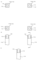
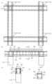
図1、図2は本発明の実施の形態に係るスラブ状部材の構築方法によって構築される頂版構造1の概略説明図であり、図1は概略平面図、図2は概略側面断面図を示している。なお、この頂版構造1は、例えばカルバートの側壁を支持部材とし、複数の支持部材に跨って搭載されるスラブ状部材の一例である。ここで、図2には、説明のため、頂版構造1に加え、支持部材(後述する支持部材10)や、最終的には撤去される場合もある、吊り下げ材を含む支保工(後述する支保工30)等についても図示している。
<Composition of top plate structure>
1 and 2 are schematic explanatory views of a
図1、2に示すように、頂版構造1は例えばカルバートの側壁、中壁等である一対の支持部材10(10a、10b)に跨って搭載される。支持部材10は、上面において後述するプレキャストスラブ20を搭載するための肩部12と、肩部12から更に上方に向かって延伸する頂部14と、を含む。頂版構造1は、一対の支持部材10に跨るように、その幅方向(図中X方向)端部が向かい合う肩部12、12に搭載される複数のプレキャストスラブ20を含む。本実施の形態に係る構成では、複数のプレキャストスラブ20がカルバートの長さ方向(図中Y方向)に隣接するように搭載されている。
As shown in FIGS. 1 and 2, the
プレキャストスラブ20は、工場などで予め製作された部材(いわゆるプレキャスト部材)であっても良く、補強材27を含むように構成することで補強されても良い。補強材27は特に限定されないが、例えばH形鋼、PC鋼材といった鋼材や鉄筋であっても良い。
プレキャストスラブ20の上方において、支持部材10の向かい合う頂部14、14に掛け渡されるように支保工30が設置される。支保工30は例えばH形鋼であっても良い。支保工30には下方に向かって伸びる複数の吊り下げ材33が連結されている。吊り下げ材33としては、異形鉄筋、セパレーター、PC鋼材、総ネジボルトといった種々の鋼材が用いられても良い。
A shoring 30 is installed above the
支保工30と吊り下げ材33の連結手段は任意であり、例えば、支保工30に孔開け加工を施し、吊り下げ材33の上端に雄ネジ加工を施し、支保工30と吊り下げ材33の連結部において雄ネジ加工とナットを締結させることで連結させても良い。
The means for connecting the shoring 30 and the hanging
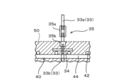
図3は吊り下げ材33の構成の一例を示す概略説明図であり、図2中の破線部を拡大して図示したものである。一例として、図3のように、吊り下げ材33は、支保工30に連結される上部吊り下げ材33aと、プレキャストスラブ20と連結される下部吊り下げ材33bと、から構成されても良い。下部吊り下げ材33bの上端には定着具34が備えられても良い。下部吊り下げ材33bの下端にも同様の定着具(図3では図示せず)が備えられても良い。図3のように、上部吊り下げ材33aと下部吊り下げ材33bは、ナット35aやPコン35bを含む継手35により連結された構成でも良い。
FIG. 3 is a schematic explanatory diagram showing an example of the configuration of the hanging
また、支保工30によるプレキャストスラブ20吊り下げ時には、吊り下げ材33の下端と、プレキャストスラブ20あるいは補強材27と、が連結される。その連結手段は任意であり、例えば補強材27に孔開け加工を施し、加工された孔を介して図示しないナットと雄ネジ加工とを螺合させることで連結しても良い。
Further, when the
プレキャストスラブ20の上方には鉄筋構造40が構築される。この鉄筋構造40は、プレキャストスラブ20の幅方向に平行に設置される複数の主鉄筋44と、主鉄筋44と交差する方向(例えば直交する方向)に設置される複数の配力筋42と、を含む。ここで、吊り下げ材33の少なくとも一部は、主鉄筋44と配力筋42の一方又は両方に係留されても良い。なお、この鉄筋構造40はオフサイトで予め製作したものでも良い。「オフサイト」とは、据え付け場所とは異なる場所であることを示し、据え付け場所そのものを除外する概念である。即ち、「オフサイトにて製作する」との記載は、例えば、工場や据え付け場所の近傍で製作する場合を含んでいる。
A reinforcing
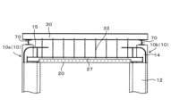
プレキャストスラブ20の上方においては、吊り下げ材33の少なくとも一部及び鉄筋構造40を埋設するようにコンクリート打設された現場打ちコンクリート部50が構成される。図2のように、現場打ちコンクリート部50の構成時には、吊り下げ材33の少なくとも一部及び鉄筋構造40を内部に埋設させ、肩部12の上部に対してもコンクリート打設が行われる。例えばその上面位置が高さ方向で頂部14の上端と一致するようにコンクリート打設が行われても良い。
Above the
以上、図1~3を参照して説明したように頂版構造1は構成される。なお、頂版構造1においては、その構築過程において図2に示した支保工30が用いられ、プレキャストスラブ20が吊り下げられる。但し、最終的な頂版構造1の構築後には、この支保工30は撤去される。支保工30の撤去は、例えば上部吊り下げ材33aと下部吊り下げ材33bの継手35を介した連結を解除することで実施されても良い。
The
<頂版構造の構築方法>
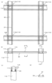
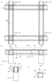
次に、上記説明した頂版構造1の構築方法について説明する。図4~図10は本発明の実施の形態に係るスラブ状部材の構築方法を適用して頂版構造1を構築する場合の工程図であり、図4から図10までの順に工程が実施される。なお、図4~図10の各図面には、説明のため(a)に概略平面図、(b)に概略側面断面図、(c)にA-A断面図を示し、更に、図5~図10には(d)にB-B断面図を示している。
<How to construct the top plate structure>
Next, a method of constructing the
先ず、図4に示すように、例えばカルバートの側壁である一対の支持部材10(10a、10b)が構築される。支持部材10は肩部12及び頂部14を含むように構築され、その内部には鉄筋15が埋設されていても良い。なお、支持部材10は工場などで予め製作された部材(いわゆるプレキャスト部材)でも良く、現場打ちにより構築されても良い。
First, as shown in FIG. 4, a pair of support members 10 (10a, 10b), which are, for example, side walls of a culvert, are constructed. The
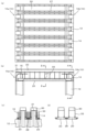
そして、図5に示すように、一対の支持部材10(10a、10b)のそれぞれの肩部12に、プレキャストスラブ20の幅方向端部を搭載することで、プレキャストスラブ20が対向する支持部材10に掛け渡される。例えば、図5(a)のように、複数のプレキャストスラブ20がカルバート長さ方向に設置されても良く、その際に、補強材27は隣り合う頂部14の間に形成された隙間に配置されるようにプレキャストスラブ20の設置が行われても良い。
As shown in FIG. 5, by mounting the widthwise ends of the
また、図5(c)、(d)に示すように、プレキャストスラブ20には、プレキャストスラブ20幅方向に延伸する配力筋28が、その端部が当該プレキャストスラブ20から突出するように埋設されていても良い。そして、複数のプレキャストスラブ20が設置される場合には、隣り合うプレキャストスラブ20同士が配力筋28同士を例えば継手構造によって連結させることで一体的に構成されても良い。継手構造の具体的構成は任意であり、例えばループ継手、機械式継手、ハーフフラップ継手等であっても良い。
Further, as shown in FIGS. 5(c) and 5(d), distribution bars 28 extending in the width direction of the
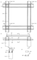
そして、図6に示すように、プレキャストスラブ20の上方において、一対の支持部材10(10a、10b)の頂部14同士に掛け渡されるように、支保工30が設置される。その際、支保工30と頂部14との間に、支保工30の高さ調整を行うためのスペーサー31を設置しても良い。
As shown in FIG. 6, the shoring 30 is installed above the
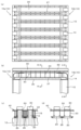
そして、図7に示すように、支保工30から下方に向かって伸びる複数の吊り下げ材33が設置される。吊り下げ材33は、例えばその上端が支保工30に連結され、その下端がプレキャストスラブ20の本体又は補強材27に連結され、これによりプレキャストスラブ20が強固に吊り下げられる。なお、図7では、吊り下げ材33と補強材27が連結した構成を図示している。
Then, as shown in FIG. 7, a plurality of hanging
支保工30と吊り下げ材33との連結手段は任意である。例えば、吊り下げ材33の上端部に雄ネジ加工を施し、支保工30に孔開け加工を行い、加工された孔を介して図示しないナットと雄ネジ加工とを螺合させることで連結しても良い。また、例えば、図3を参照して説明した構成において、上部吊り下げ材33aを支保工30に同様の方法で連結させても良い。
The means for connecting the shoring 30 and the hanging
また、吊り下げ材33とプレキャストスラブ20との連結手段は任意である。例えば、図3を参照して説明した下部吊り下げ材33bを予めプレキャストスラブ20に埋設しても良い。このように構成された上部吊り下げ材33aと下部吊り下げ材33bを継手35でもって連結させ、プレキャストスラブ20の吊り下げを行っても良い。
Moreover, the means for connecting the hanging
吊り下げ材33を介した支保工30によるプレキャストスラブ20の吊り下げ時には、支保工30と吊り下げ材33との連結箇所において吊り下げ材33を上下させることで、吊り下げられたプレキャストスラブ20の姿勢を調整しても良い。吊り下げ材33の上下動は、例えば支保工30と吊り下げ材33との連結手段として用いたナットを締緩することにより行っても良い。
When the
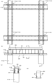
そして、図8に示すように、プレキャストスラブ20の上方において鉄筋構造40が構築される。この時、吊り下げ材33の少なくとも一部を、鉄筋構造40を構成する配力筋42と主鉄筋44の一方又は両方に係留しても良い。鉄筋構造40は現場において構築しても良く、あるいはオフサイトで予め製作したものを設置しても良い。
Then, as shown in FIG. 8, a reinforcing
そして、図9に示すように、吊り下げ材33の少なくとも一部及び鉄筋構造40を埋設するようにコンクリートの打設及び養生が行われ、現場打ちコンクリート部50が構成される(図中の破線部参照)。図示のように、現場打ちコンクリート部50の天端高さと、支持部材10の頂部14の上端の高さ一致するようにコンクリートの打設及び養生が行われても良い。
Then, as shown in FIG. 9, concrete is placed and cured so as to bury at least a portion of the hanging
そして、図10に示すように、支保工30と吊り下げ材33の少なくとも一部を分離させ、支保工30の撤去(図中の破線参照)が行われる。支保工30の撤去は、例えば図3に示す上部吊り下げ材33aと下部吊り下げ材33bを継手35で連結させた構成において、継手35の連結を解除し、ナット35aやPコン35bを撤去して行われても良い。
Then, as shown in FIG. 10, at least a portion of the shoring 30 and the hanging
以上、図4~図10を参照して説明した構築方法により、プレキャストスラブ20と現場打ちコンクリート部50からなるスラブ状部材としての頂版構造1が構築される。
By the construction method described above with reference to FIGS. 4 to 10, the
<プレキャストスラブの構成>
プレキャストスラブ20は工場などで予め製作された部材であっても良く、その構成は任意である。即ち、吊り下げ材33の下端(下部吊り下げ材33bの下端)を連結させて吊り下げることが可能であればその構成は限定されるものではない。以下では、プレキャストスラブ20の構成の一例について図11を参照して説明する。図11はプレキャストスラブ20の構成の一例を示す概略説明図であり、(a)、(b)ともにその幅方向断面図である。
<Precast slab composition>
The
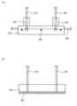
図11(a)に示すように、プレキャストスラブ20の構成の一例として、吊り下げ材33の下端を内部に埋設しても良く、その埋設箇所にプレキャストスラブ20の上方に突出する突起部22を有しても良い。突起部22を設けることで、吊り下げ材33をプレキャストスラブ20に埋設させる際の定着効率や引抜耐力を向上させることができる。また、図示のように、プレキャストスラブ20の内部において、上記配力筋28と直交する方向(長手方向)に延伸する1又は複数の主鉄筋24を埋設しても良い。これによりプレキャストスラブ20自体の強度を向上させることができる。
As shown in FIG. 11(a), as an example of the structure of the
また、図11(b)に示すように、プレキャストスラブ20の構成の一例として、その下面に鋼板25を設置しても良い。加えて、プレキャストスラブ20に埋設させた吊り下げ材33を鋼板25に接合しても良い。これにより、吊り下げ材33の定着効率向上に加え、プレキャストスラブ20へのひび割れ発生を抑制あるいは許容することができる。
Further, as shown in FIG. 11(b), as an example of the configuration of the
なお、プレキャストスラブ20の製作においては、例えばFRC(Fiber Reinforced Concrete:繊維補強コンクリート)を用いても良い。これによりプレキャストスラブ20自体の強度や靭性を高めることができる。例えば、プレキャストスラブ20が補強材27及び上記のFRCによって補強され、コンクリート打設前の施工時荷重に対して十分な曲げ剛性を有している場合には、以下のような施工手順を採ることもできる。即ち、プレキャストスラブ20を設置した後、鉄筋構造40を構築し、その後、支保工30を設置して吊り下げ材33とプレキャストスラブ20の本体又は補強材27とを連結させ、コンクリート打設により現場打ちコンクリート部50を構成させても良い。
In addition, in manufacturing the
図4~図10を参照して上述したような、支保工30が設置された状態で鉄筋構造40を構築する場合には、上方が一部閉鎖された状態で作業が行われる。そのため、構造条件によっては作業効率の低下が懸念される。一方、鉄筋構造40を構築した後に支保工30の設置を行う手順によれば、上方が開放された状態で鉄筋構造40を構築できるため、資材の搬入や鉄筋組立といった作業効率の向上が図られる。
When constructing the reinforcing
<プレキャストスラブと吊り下げ材との連結>
上述した頂版構造1の構築方法においては、図7を参照して説明した吊り下げ材33を介した支保工30によるプレキャストスラブ20の吊り下げが重要な工程である。吊り下げ時の連結手段やその構成は、吊り下げ材33とプレキャストスラブ20とを確実に連結できるものであれば特に限定されるものではない。ここでは、プレキャストスラブ20と吊り下げ材33との連結手段やその構成の一例について説明する。
<Connection of precast slab and hanging material>
In the method for constructing the
図12は、プレキャストスラブ20と吊り下げ材33との連結に関する概略説明図であり、連結の構成を模式的に図示したものである。図12に示すように、プレキャストスラブ20に吊り下げ材33の下端(下部吊り下げ材33bの下端)を連結させる際には種々の構成が考え得る。
FIG. 12 is a schematic explanatory diagram regarding the connection between the
例えば、吊り下げ材33の下端(下部吊り下げ材33bの下端)に定着具32を有する構成とし、図12(a)のように定着具32を含めて吊り下げ材33の下端を直接プレキャストスラブ20に埋設させても良い。これにより、吊り下げ材33のプレキャストスラブ20に対する定着効率や引抜耐力を向上させることができる。
For example, the structure has a fixing
また、例えば、図12(b)のようにプレキャストスラブ20にインサート36を埋設し、ネジ加工した吊り下げ材33の下端をインサート36に接続して連結しても良い。
Alternatively, for example, as shown in FIG. 12(b), an
また、例えば、図12(c)のようにプレキャストスラブ20に切欠き37を形成し、下端に定着具32を有する吊り下げ材33を切欠き37に挿入しグラウト38の充填を行うことで連結しても良い。
Alternatively, for example, as shown in FIG. 12(c), a
また、例えば、図12(d)のようにプレキャストスラブ20に鋼管39を設置し、下端に定着具32を有する吊り下げ材33を鋼管39に挿入しグラウト38の充填を行うことで連結しても良い。
Alternatively, for example, as shown in FIG. 12(d), a
<支保工の構成>
上述したように、支保工30としては例えばH形鋼が例示され、吊り下げ材33との連結は支保工30に孔開け加工を施し、吊り下げ材33の上端に雄ネジ加工を施し、支保工30と吊り下げ材33の連結部において雄ネジ加工とナットを締結させることで行われる。但し、これに限定されるものではなく、支保工30の構成や吊り下げ材33の上端との連結構成については種々のものが考え得る。
<Shoring structure>
As mentioned above, the
図13は支保工30として溝形鋼を用いた場合の概略断面図である。図13に示すように、支保工30を2本の溝形鋼30a、30bからなる構成とし、2本の溝形鋼30a、30b間に吊り下げ材33を設置し、定着板60及びナット61で吊り下げ材33を接合しても良い。これにより、孔開け加工量の低減が図られる。
FIG. 13 is a schematic cross-sectional view when channel steel is used as the shoring 30. As shown in FIG. 13, the shoring 30 is made up of two
また、支保工30の設置において、支保工30と頂部14との間に例えばH形鋼等である架台70を介しても良い。図21は支保工30と頂部14との間に架台70を介して支保工30の設置を行う場合の概略図である。例えば、架台70を隣り合う頂部14に跨るように設置し、隣り合う頂部14の支間中央位置において架台70上に支保工30を設置することで、隣り合う頂部14の設置間隔を大きく設計することができる。
Further, in installing the shoring 30, a
<作用効果>
以上説明したスラブ状部材としての頂版構造1の構築方法によれば、支保工30を用いてプレキャストスラブ20を吊り下げる工程において、吊り下げ材33を用い、その吊り下げ材33の少なくとも一部を現場打ちコンクリート部50に埋設させている。これにより、頂版構造1において、吊り下げ材33の少なくとも一部がせん断補強筋として機能する。即ち、プレキャストスラブ20と現場打ちコンクリート部50からなるスラブ状部材としての頂版構造1において十分なせん断耐力が担保される。
<Effect>
According to the construction method of the
また、頂版構造1において、吊り下げ材33をせん断補強筋として機能させることにより、別途せん断補強筋を配筋する必要がないため、鉄筋工における作業性の向上や工期短縮が図られる。加えて、鉄筋構造40をオフサイトで予め製作したものとしてユニット化させることで鉄筋の施工作業性が向上する。
Furthermore, in the
また、支保工30を用い、吊り下げ材33を介してプレキャストスラブ20を吊り下げる際に、プレキャストスラブ20と吊り下げ材33との連結や、支保工30と吊り下げ材33との連結において、図11~図13を参照して説明したような種々の連結構成を用いることで、定着効率や引抜耐力の向上が図られる。
Moreover, when suspending the
以上、本発明の実施の形態の一例を説明したが、本発明は図示の形態に限定されない。当業者であれば、特許請求の範囲に記載された思想の範疇内において、各種の変更例または修正例に想到し得ることは明らかであり、それらについても当然に本発明の技術的範囲に属するものと了解される。 Although an example of the embodiment of the present invention has been described above, the present invention is not limited to the illustrated embodiment. It is clear that those skilled in the art can come up with various changes or modifications within the scope of the idea described in the claims, and these naturally fall within the technical scope of the present invention. It is understood that
例えば、上記実施の形態では、上部吊り下げ材33aと下部吊り下げ材33bとの連結手段の一例として継手35を用いた構成について説明したが、連結手段はこれに限られない。即ち、連結手段として、貫通式定着体及び機械式継手により連結を行い、ナット及び発泡スチロールによる箱抜きを用いても良い。また、連結時のがたつきを解消するために、ターンバックルを用いても良い。
For example, in the above embodiment, a configuration using the joint 35 as an example of a connecting means between the upper hanging
上記実施の形態では、吊り下げ材33の構成として上部吊り下げ材33aと下部吊り下げ材33bが継手35で連結された構成について図3に図示したが、吊り下げ材33の構成はこれに限られるものではない。図22は吊り下げ材33の他の構成例を示す概略説明図であり、(a)は俯瞰図、(b)は側面図である。なお、図22において上記実施の形態と同じ機能構成を有する構成要素については、同一の符号を付して図示し、説明は省略する場合がある。
In the above embodiment, the configuration of the hanging
図22に示すように、吊り下げ材33は、例えば、非金属で形成されるフック状上部吊り下げ材33cと、竹節鉄筋又はねじ節鉄筋で形成されるフック状下部吊り下げ材33dから構成されても良い。これらフック状上部吊り下げ材33cとフック状下部吊り下げ材33dは高さ方向において互いに突き合わせた状態で係止し接続することが可能に構成される。図示のように、フック状上部吊り下げ材33cとフック状下部吊り下げ材33dは鉄筋構造40の配力筋42を介して接続されても良い。
As shown in FIG. 22, the hanging
頂版構造1を構築するに際し、フック状上部吊り下げ材33cは残置しても良く、あるいは現場打ちコンクリート部50の上面位置において切断しても良い。フック状上部吊り下げ材33cは非金属で形成されるため、防錆処理等は不要である。吊り下げ材33をこのような構成にすることで、フック状下部吊り下げ材33dの撤去や、箱抜きを用いた際の箱埋め処理等が必要なくなり、省力化が図られる。
When constructing the
<本発明の他実施形態>
上記実施の形態においては、本発明に係るスラブ状部材の構築方法により構築される頂版構造1を例示して図示説明したが、本発明の適用範囲はこれに限られるものではない。具体的には、スラブ状部材として梁を構築する場合にも適用できる。以下、本発明の他実施形態として、本発明に係るスラブ状部材の構築方法を用いて梁を構築する方法について図面を参照して説明する。なお、以下の他実施形態に係る説明において、上記実施の形態と同じ機能構成を有する構成要素については、同一の符号を付して図示し、説明は省略する場合がある。
<Other embodiments of the present invention>
In the embodiment described above, the
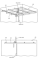
図14~図20は本発明に係るスラブ状部材の構築方法を適用して梁100を構築する場合の工程図であり、図14から図20までの順に工程が実施される。なお、図14~図20の各図面には、説明のため(a)に概略平面図、(b)に概略側面断面図、(c)にA-A断面図を示し、更に、図5~図10には(d)にB-B断面図を示している。
14 to 20 are process diagrams for constructing the
先ず、図14に示すように、柱部材としての支持部材110(110a、110b、110c、110d)が構築される。支持部材110の配置は梁100の構造に応じて任意に設計される。本形態では平面視において略四角形状である梁100が構築される場合を図示し、その際には支持部材110は四方4箇所に配置される。支持部材110は肩部112と、その上部に設けられる頂部114を含むように構築される。肩部112の周縁部には、上方に向けて突出する鉄筋115が埋設されても良い。なお、支持部材110は工場などで予め製作された部材(いわゆるプレキャスト部材)でも良く、現場打ちにより構築されても良い。
First, as shown in FIG. 14, support members 110 (110a, 110b, 110c, 110d) as pillar members are constructed. The arrangement of the
そして、図15に示すように、支持部材110(110a、110b、110c、110d)のそれぞれ向かい合う肩部112に、プレキャストスラブ20の幅方向端部を搭載することで、プレキャストスラブ20が対向する支持部材110に掛け渡される。例えば、図15(a)のように、4本のプレキャストスラブ20が略四角形状に掛け渡されても良い。ここで、隣り合うプレキャストスラブ20に含まれる補強材27同士は、交差部128において溶接等の手段により接続しても良い。
Then, as shown in FIG. 15, by mounting the width direction ends of the
そして、図16に示すように、プレキャストスラブ20の上方において、支持部材110(110a、110b、110c、110d)の頂部14同士に掛け渡されるように、支保工30が設置される。その際、支保工30と頂部114との間に、支保工30の高さ調整を行うためのスペーサー31を設置しても良い。
As shown in FIG. 16, the shoring 30 is installed above the
そして、図17に示すように、支保工30から下方に向かって伸びる複数の吊り下げ材33が設置される。吊り下げ材33は、例えばその上端が支保工30に連結され、その下端がプレキャストスラブ20の本体又は補強材27に連結され、これによりプレキャストスラブ20が強固に吊り下げられる。なお、図17では、吊り下げ材33と補強材27が連結した構成を図示している。支保工30と吊り下げ材33との連結手段や、吊り下げ材33とプレキャストスラブ20との連結手段は任意であり、上記実施の形態で説明した構成にて連結が行われても良い。
Then, as shown in FIG. 17, a plurality of hanging
そして、図18に示すように、プレキャストスラブ20の上方において鉄筋構造40が構築される。この時、上記実施の形態と同様に、吊り下げ材33の少なくとも一部を、鉄筋構造40に係留しても良い。鉄筋構造40は現場において構築しても良く、あるいはオフサイトで予め製作したものを設置しても良い。
Then, as shown in FIG. 18, a reinforcing
そして、図19に示すように、吊り下げ材33の少なくとも一部及び鉄筋構造40を埋設するようにコンクリートの打設及び養生が行われ、現場打ちコンクリート部50が構成される(図中の破線部参照)。図示のように、現場打ちコンクリート部50の天端高さと、頂部114の上端の高さ一致するようにコンクリートの打設及び養生が行われても良い。
Then, as shown in FIG. 19, concrete is placed and cured so as to bury at least a portion of the hanging
そして、図20に示すように、支保工30と吊り下げ材33の少なくとも一部を分離させ、支保工30の撤去(図中の破線参照)が行われる。支保工30の撤去は、上記実施の形態で説明したように、例えば、継手35の連結を解除し、ナット35aやPコン35bを撤去して行われても良い。
Then, as shown in FIG. 20, at least a portion of the shoring 30 and the hanging
以上、図14~図20を参照して説明した構築方法により、プレキャストスラブ20と現場打ちコンクリート部50からなるスラブ状部材としての梁100が構築される。このように、本発明に係るスラブ状部材の構築方法を梁・柱構造に適用させることで、梁100を構築する際にも、上記実施の形態と同様に作業性の向上や工期の短縮を図ることができる。
By the construction method described above with reference to FIGS. 14 to 20, the
また、本明細書に記載された効果は、あくまで説明的または例示的なものであって限定的ではない。つまり、本開示に係る技術は、上記の効果とともに、又は、上記の効果に代えて、本明細書の記載から当業者には明らかな他の効果を奏しうる。 Further, the effects described in this specification are merely explanatory or illustrative, and are not limiting. In other words, the technology according to the present disclosure can have other effects that are obvious to those skilled in the art from the description of this specification, in addition to or in place of the above effects.
なお、以下のような構成も本発明の技術的範囲に属する。
(1)プレキャストスラブと現場打ちコンクリートからなり、一対の支持部材に跨って搭載されるハーフプレキャストコンクリート製のスラブ状部材の構築方法であって、前記一対の支持部材に前記プレキャストスラブの幅方向端部を搭載する工程と、前記プレキャストスラブの上方に掛け渡した支保工により当該支保工から下方に向かって伸びる吊り下げ材を介して前記プレキャストスラブを吊り下げる工程と、前記プレキャストスラブの上方に鉄筋構造を構築する工程と、前記吊り下げ材の少なくとも一部と前記鉄筋構造を埋設するように前記プレキャストスラブの上部に現場打ちコンクリートを打設し養生する工程と、前記支保工から前記吊り下げ材を分離し、前記支保工を撤去する工程と、を含み、前記スラブ状部材において前記現場打ちコンクリートに埋設された前記吊り下げ材はせん断補強筋として機能することを特徴とする、スラブ状部材の構築方法。
(2)前記プレキャストスラブは当該プレキャストスラブに埋設された補強材によって補強され、前記プレキャストスラブを吊り下げる工程においては、前記吊り下げ材の下端を前記補強材又は前記プレキャストスラブに連結させることを特徴とする、(1)に記載のスラブ状部材の構築方法。
(3)前記吊り下げ材の上端部には雄ネジ加工が施され、前記プレキャストスラブを吊り下げる工程においては、前記支保工と前記吊り下げ材の連結部において前記雄ネジに螺合するナットを締緩することにより前記吊り下げ材を上下させ、前記プレキャストスラブの姿勢を調整することを特徴とする、(1)又は(2)に記載のスラブ状部材の構築方法。
(4)前記吊り下げ材は、前記支保工に連結される上部吊り下げ材と、前記プレキャストスラブと連結される下部吊り下げ材と、が継手によって連結された構造を有し、前記支保工を撤去する工程においては、前記継手を外すことにより前記下部吊り下げ材を前記支保工から分離させることを特徴とする、(1)~(3)のいずれか一項に記載のスラブ状部材の構築方法。
(5)前記下部吊り下げ材の上端及び下端に定着具を有することを特徴とする、(4)に記載のスラブ状部材の構築方法。
(6)前記支持部材は、肩部と、当該肩部から上方に延伸する頂部と、を備え、前記プレキャストスラブの幅方向端部は前記肩部上に搭載され、前記支保工は前記一対の支持部材の前記頂部上に掛け渡すように搭載されることを特徴とする、(1)~(5)のいずれか一項に記載のスラブ状部材の構築方法。
(7)前記支持部材はカルバートの壁であり、前記スラブ状部材は前記カルバートの頂版であることを特徴とする、(1)~(6)のいずれか一項に記載のスラブ状部材の構築方法。
(8)前記支持部材は柱であり、前記スラブ状部材は梁であることを特徴とする、(1)~(6)のいずれか一項に記載のスラブ状部材の構築方法。
(9)前記鉄筋構造は、前記プレキャストスラブの幅方向に平行に設置される主鉄筋と、前記主鉄筋と交差する方向に設置される配力筋と、を含み、前記吊り下げ材は、前記主鉄筋と前記配力筋の一方又は両方に係留されることを特徴とする、(1)~(8)のいずれか一項に記載のスラブ状部材の構築方法。
(10)前記プレキャストスラブは互いに隣接して複数搭載され、前記プレキャストスラブには、当該プレキャストスラブの幅方向に延伸する配力筋が、当該配力筋の端部が当該プレキャストスラブから突出するように埋設され、複数の前記プレキャストスラブにおいて、隣り合う前記プレキャストスラブ同士は前記配力筋同士を継手により連結し、前記現場打ちコンクリートを打設し養生する工程では、隣接する複数のプレキャストスラブ間も含めてコンクリート打設が行われることを特徴とする、(1)~(7)のいずれか一項に記載のスラブ状部材の構築方法。
(11)前記支持部材はカルバートの壁であり、前記スラブ状部材は前記カルバートの頂版であり、複数の前記プレキャストスラブは、前記カルバートの長さ方向において複数設置されることを特徴とする、(10)に記載のスラブ状部材の構築方法。
Note that the following configurations also belong to the technical scope of the present invention.
(1) A method for constructing a half precast concrete slab-like member consisting of a precast slab and cast-in-place concrete and mounted across a pair of supporting members, the widthwise end of the precast slab being mounted on the pair of supporting members. a step of suspending the precast slab via a hanging member extending downward from the shoring by a shoring strung above the precast slab; a step of constructing a structure; a step of pouring and curing cast-in-place concrete on top of the precast slab so as to bury at least a portion of the hanging material and the reinforcing steel structure; and removing the shoring, wherein the hanging material embedded in the cast-in-place concrete in the slab-like member functions as a shear reinforcement. Construction method.
(2) The precast slab is reinforced by a reinforcing material embedded in the precast slab, and in the step of suspending the precast slab, the lower end of the hanging material is connected to the reinforcing material or the precast slab. The method for constructing a slab-like member according to (1).
(3) The upper end of the hanging material is machined with a male thread, and in the process of suspending the precast slab, a nut is screwed into the male screw at the connecting part between the shoring and the hanging material. The method for constructing a slab-like member according to (1) or (2), characterized in that the posture of the precast slab is adjusted by moving the hanging member up and down by tightening and loosening it.
(4) The hanging material has a structure in which an upper hanging material connected to the shoring and a lower hanging material connected to the precast slab are connected by a joint, and the hanging material is connected to the shoring by a joint. Construction of the slab-like member according to any one of (1) to (3), characterized in that in the step of removing, the lower hanging member is separated from the support by removing the joint. Method.
(5) The method for constructing a slab-like member according to (4), characterized in that fixing devices are provided at the upper and lower ends of the lower hanging member.
(6) The support member includes a shoulder portion and a top portion extending upward from the shoulder portion, the widthwise end portion of the precast slab is mounted on the shoulder portion, and the shoring member is provided with a The method for constructing a slab-like member according to any one of (1) to (5), characterized in that the method is mounted so as to span over the top of the support member.
(7) The slab-like member according to any one of (1) to (6), wherein the supporting member is a wall of a culvert, and the slab-like member is a top plate of the culvert. Construction method.
(8) The method for constructing a slab-like member according to any one of (1) to (6), wherein the supporting member is a column and the slab-like member is a beam.
(9) The reinforcing bar structure includes main reinforcing bars installed parallel to the width direction of the precast slab, and distribution bars installed in a direction intersecting the main reinforcing bars, and the hanging material includes the The method for constructing a slab-like member according to any one of (1) to (8), characterized in that the slab-like member is moored to one or both of the main reinforcement and the distribution reinforcement.
(10) A plurality of the precast slabs are mounted adjacent to each other, and the precast slab has distribution bars extending in the width direction of the precast slab such that the ends of the distribution bars protrude from the precast slab. In the plurality of precast slabs, the distribution bars of the adjacent precast slabs are connected by joints, and in the process of pouring and curing the cast-in-place concrete, the adjacent precast slabs are also The method for constructing a slab-like member according to any one of (1) to (7), characterized in that concrete placement is performed including concrete placement.
(11) The supporting member is a wall of the culvert, the slab-like member is a top plate of the culvert, and the plurality of precast slabs are installed in the longitudinal direction of the culvert. The method for constructing a slab-like member according to (10).
本発明は、ハーフプレキャストコンクリート製のスラブ状部材を構築する構築方法に適用できる。 The present invention can be applied to a construction method for constructing a slab-like member made of half precast concrete.
1…頂版構造
10…支持部材
12…肩部
14…頂部
15…鉄筋
20…プレキャストスラブ
27…補強材
28…(プレキャストスラブの)配力筋
30…支保工
33…吊り下げ材
34…定着具
35…継手
40…鉄筋構造
42…配力筋
44…主鉄筋
50…現場打ちコンクリート部
100…梁
1...
Claims (11)
前記一対の支持部材に前記プレキャストスラブの幅方向端部を搭載する工程と、
前記プレキャストスラブの上方に掛け渡した支保工により当該支保工から下方に向かって伸びる吊り下げ材を介して前記プレキャストスラブを吊り下げる工程と、
前記プレキャストスラブの上方に鉄筋構造を構築する工程と、
前記吊り下げ材の少なくとも一部と前記鉄筋構造を埋設するように前記プレキャストスラブの上部に現場打ちコンクリートを打設し養生する工程と、
前記支保工から前記吊り下げ材を分離し、前記支保工を撤去する工程と、を含み、
前記スラブ状部材において前記現場打ちコンクリートに埋設された前記吊り下げ材はせん断補強筋として機能することを特徴とする、スラブ状部材の構築方法。 A method for constructing a half-precast concrete slab-like member that is composed of a precast slab and cast-in-place concrete and is mounted across a pair of supporting members, the method comprising:
a step of mounting the width direction end portions of the precast slab on the pair of support members;
a step of suspending the precast slab via a hanging member extending downward from the shoring by a shoring strung above the precast slab;
constructing a reinforcing structure above the precast slab;
pouring and curing cast-in-place concrete on top of the precast slab so as to bury at least a portion of the hanging material and the reinforcing structure;
Separating the hanging material from the shoring and removing the shoring,
A method of constructing a slab-like member, wherein the hanging material embedded in the cast-in-place concrete in the slab-like member functions as a shear reinforcing bar.
前記プレキャストスラブを吊り下げる工程においては、前記吊り下げ材の下端を前記補強材又は前記プレキャストスラブに連結させることを特徴とする、請求項1に記載のスラブ状部材の構築方法。 The precast slab is reinforced by a reinforcing material embedded in the precast slab,
2. The method of constructing a slab-like member according to claim 1, wherein in the step of suspending the precast slab, a lower end of the hanging member is connected to the reinforcing member or the precast slab.
前記支保工を撤去する工程においては、前記継手を外すことにより前記下部吊り下げ材を前記支保工から分離させることを特徴とする、請求項1又は2に記載のスラブ状部材の構築方法。 The hanging material has a structure in which an upper hanging material connected to the shoring and a lower hanging material connected to the precast slab are connected by a joint,
3. The method for constructing a slab-like member according to claim 1, wherein in the step of removing the support, the lower hanging member is separated from the support by removing the joint.
前記プレキャストスラブの幅方向端部は前記肩部上に搭載され、
前記支保工は前記一対の支持部材の前記頂部上に掛け渡すように搭載されることを特徴とする、請求項1又は2に記載のスラブ状部材の構築方法。 The support member includes a shoulder and a top extending upward from the shoulder,
a widthwise end of the precast slab is mounted on the shoulder;
3. The method for constructing a slab-like member according to claim 1, wherein the shoring is mounted so as to span over the tops of the pair of support members.
前記吊り下げ材は、前記主鉄筋と前記配力筋の一方又は両方に係留されることを特徴とする、請求項1又は2に記載のスラブ状部材の構築方法。 The reinforcing bar structure includes main reinforcing bars installed in parallel to the width direction of the precast slab, and distribution bars installed in a direction intersecting the main reinforcing bars,
3. The method of constructing a slab-like member according to claim 1, wherein the hanging member is moored to one or both of the main reinforcing bars and the distribution bars.
前記プレキャストスラブには、当該プレキャストスラブの幅方向に延伸する配力筋が、当該配力筋の端部が当該プレキャストスラブから突出するように埋設され、
複数の前記プレキャストスラブにおいて、隣り合う前記プレキャストスラブ同士は前記配力筋同士を継手により連結し、前記現場打ちコンクリートを打設し養生する工程では、隣接する複数のプレキャストスラブ間も含めてコンクリート打設が行われることを特徴とする、請求項1又は2に記載のスラブ状部材の構築方法。 A plurality of the precast slabs are mounted adjacent to each other,
A distribution bar extending in the width direction of the precast slab is embedded in the precast slab such that an end of the distribution bar protrudes from the precast slab,
In the plurality of precast slabs, the distribution bars of the adjacent precast slabs are connected by joints, and in the process of pouring and curing the cast-in-place concrete, concrete is poured between the plurality of adjacent precast slabs as well. The method for constructing a slab-like member according to claim 1 or 2, characterized in that:
10. The supporting member is a wall of the culvert, the slab-like member is a top plate of the culvert, and the plurality of precast slabs are installed in the longitudinal direction of the culvert. A method for constructing a slab-like member as described in .
Priority Applications (1)
| Application Number | Priority Date | Filing Date | Title |
|---|---|---|---|
| JP2022078692A JP2023167478A (en) | 2022-05-12 | 2022-05-12 | Construction method for slab-like member |
Applications Claiming Priority (1)
| Application Number | Priority Date | Filing Date | Title |
|---|---|---|---|
| JP2022078692A JP2023167478A (en) | 2022-05-12 | 2022-05-12 | Construction method for slab-like member |
Publications (1)
| Publication Number | Publication Date |
|---|---|
| JP2023167478A true JP2023167478A (en) | 2023-11-24 |
Family
ID=88838008
Family Applications (1)
| Application Number | Title | Priority Date | Filing Date |
|---|---|---|---|
| JP2022078692A Pending JP2023167478A (en) | 2022-05-12 | 2022-05-12 | Construction method for slab-like member |
Country Status (1)
| Country | Link |
|---|---|
| JP (1) | JP2023167478A (en) |
Citations (12)
| Publication number | Priority date | Publication date | Assignee | Title |
|---|---|---|---|---|
| JPH09279609A (en) * | 1996-04-11 | 1997-10-28 | Tokyu Koken Kk | Building method of precast reinforced concrete-made underground structure |
| JPH11247109A (en) * | 1998-03-05 | 1999-09-14 | Tokyu Constr Co Ltd | Construction method of ramen viaduct |
| JP2000001938A (en) * | 1998-06-15 | 2000-01-07 | Kozo Plan:Kk | Precast concrete board and floorboard structure of building |
| JP2001049779A (en) * | 1999-08-12 | 2001-02-20 | Toshiba Eng Co Ltd | Closing method of construction for floor opening for prefabricated equipment |
| JP2001132149A (en) * | 1999-11-09 | 2001-05-15 | Nippon Kaiser Kk | Precast concrete floorboard for viaduct, viaduct and construction method |
| JP2003193544A (en) * | 2001-12-26 | 2003-07-09 | Haneda Concrete Industrial Co Ltd | Concrete assembly structure |
| JP2008285119A (en) * | 2007-05-21 | 2008-11-27 | Kojima Press Co Ltd | Vehicle storage device |
| US20150167289A1 (en) * | 2013-12-13 | 2015-06-18 | Urbantech Consulting Engineering, PC | Open web composite shear connector construction |
| JP2017166229A (en) * | 2016-03-16 | 2017-09-21 | ジオスター株式会社 | Box culvert |
| JP2018141284A (en) * | 2017-02-27 | 2018-09-13 | 清水建設株式会社 | Joint structure for shear reinforcement steel member of steel concrete composite structure and joint method for shear reinforcement member of steel concrete composition structure |
| JP2019073929A (en) * | 2017-10-18 | 2019-05-16 | 五洋建設株式会社 | Concrete structure and construction method for the same |
| JP2020079496A (en) * | 2018-11-12 | 2020-05-28 | 鹿島建設株式会社 | Method for constructing top slab for underground structure |
-
2022
- 2022-05-12 JP JP2022078692A patent/JP2023167478A/en active Pending
Patent Citations (12)
| Publication number | Priority date | Publication date | Assignee | Title |
|---|---|---|---|---|
| JPH09279609A (en) * | 1996-04-11 | 1997-10-28 | Tokyu Koken Kk | Building method of precast reinforced concrete-made underground structure |
| JPH11247109A (en) * | 1998-03-05 | 1999-09-14 | Tokyu Constr Co Ltd | Construction method of ramen viaduct |
| JP2000001938A (en) * | 1998-06-15 | 2000-01-07 | Kozo Plan:Kk | Precast concrete board and floorboard structure of building |
| JP2001049779A (en) * | 1999-08-12 | 2001-02-20 | Toshiba Eng Co Ltd | Closing method of construction for floor opening for prefabricated equipment |
| JP2001132149A (en) * | 1999-11-09 | 2001-05-15 | Nippon Kaiser Kk | Precast concrete floorboard for viaduct, viaduct and construction method |
| JP2003193544A (en) * | 2001-12-26 | 2003-07-09 | Haneda Concrete Industrial Co Ltd | Concrete assembly structure |
| JP2008285119A (en) * | 2007-05-21 | 2008-11-27 | Kojima Press Co Ltd | Vehicle storage device |
| US20150167289A1 (en) * | 2013-12-13 | 2015-06-18 | Urbantech Consulting Engineering, PC | Open web composite shear connector construction |
| JP2017166229A (en) * | 2016-03-16 | 2017-09-21 | ジオスター株式会社 | Box culvert |
| JP2018141284A (en) * | 2017-02-27 | 2018-09-13 | 清水建設株式会社 | Joint structure for shear reinforcement steel member of steel concrete composite structure and joint method for shear reinforcement member of steel concrete composition structure |
| JP2019073929A (en) * | 2017-10-18 | 2019-05-16 | 五洋建設株式会社 | Concrete structure and construction method for the same |
| JP2020079496A (en) * | 2018-11-12 | 2020-05-28 | 鹿島建設株式会社 | Method for constructing top slab for underground structure |
Similar Documents
| Publication | Publication Date | Title |
|---|---|---|
| US6904636B2 (en) | Deck-to-girder connections for precast or prefabricated bridge decks | |
| CN101952514B (en) | Fit-together type of precast concrete lining and bridging structural body | |
| CN214005373U (en) | Connecting structure of precast concrete bridge deck and steel plate beam | |
| KR100447013B1 (en) | Beam system composed of asymmetric steel section with web hole and concrete | |
| JP3844743B2 (en) | Box girder bridge structure and its construction method | |
| JP4625763B2 (en) | Composite structure of main girder and precast slab | |
| CN115288034A (en) | Girder cable-free area girder section construction method for large-span steel-concrete composite beam | |
| JP2008266910A (en) | Projection structure of tendon fixing portion or deflecting portion and construction method thereof | |
| JP2000054319A (en) | Formation of concrete floor slab and construction of suspended deck bridge | |
| JP4235079B2 (en) | Structure of joint between reinforced concrete column and steel beam | |
| KR20200092593A (en) | Concrete slab of bridge with precast cantilever slab and concrete slab of bridge construction method therefor | |
| JP3737475B2 (en) | Box girder bridge structure and construction method | |
| JP3896032B2 (en) | Construction method of precast column head and pier column head | |
| JP2023167478A (en) | Construction method for slab-like member | |
| KR101824963B1 (en) | Hybrid composite girder and construction method therewith | |
| JPH04228710A (en) | Road slab for bridge | |
| CN111576845B (en) | An adjustable cantilever steel beam installation structure for building engineering external frame and construction method | |
| CN108951910B (en) | Connection structure and swing wall with T type energy dissipation piece swing wall | |
| CN1147589A (en) | Prestressed reinforced concrete structure and its construction method | |
| JP2003027404A (en) | Under-track structure construction method | |
| KR20040102391A (en) | Composite Beam Stiffened with In-Situ Concrete Panel Having Embedded Lower Flange and Constructing Method thereof | |
| KR100653283B1 (en) | Connection method of reinforced concrete structures | |
| KR100695491B1 (en) | Binding holes, formwork structures for pre-assembled concrete structures and construction methods using them | |
| CN212224301U (en) | Anti structure of splitting of infilled wall combination | |
| CN203475599U (en) | Shock-proof prefabricated building of steel tube shearing wall composite structure |
Legal Events
| Date | Code | Title | Description |
|---|---|---|---|
| A621 | Written request for application examination |
Free format text: JAPANESE INTERMEDIATE CODE: A621 Effective date: 20250226 |
|
| A977 | Report on retrieval |
Free format text: JAPANESE INTERMEDIATE CODE: A971007 Effective date: 20251021 |
|
| A131 | Notification of reasons for refusal |
Free format text: JAPANESE INTERMEDIATE CODE: A131 Effective date: 20251028 |
|
| A521 | Request for written amendment filed |
Free format text: JAPANESE INTERMEDIATE CODE: A523 Effective date: 20251219 |