JP2023143807A - Yarn winding machine - Google Patents
Yarn winding machine Download PDFInfo
- Publication number
- JP2023143807A JP2023143807A JP2023042480A JP2023042480A JP2023143807A JP 2023143807 A JP2023143807 A JP 2023143807A JP 2023042480 A JP2023042480 A JP 2023042480A JP 2023042480 A JP2023042480 A JP 2023042480A JP 2023143807 A JP2023143807 A JP 2023143807A
- Authority
- JP
- Japan
- Prior art keywords
- bobbin
- bobbin holder
- thread
- yarn
- package
- Prior art date
- Legal status (The legal status is an assumption and is not a legal conclusion. Google has not performed a legal analysis and makes no representation as to the accuracy of the status listed.)
- Pending
Links
- 238000004804 winding Methods 0.000 title claims abstract description 230
- 238000004519 manufacturing process Methods 0.000 claims abstract description 36
- 230000007246 mechanism Effects 0.000 claims description 22
- 238000000034 method Methods 0.000 description 22
- 230000008569 process Effects 0.000 description 22
- 239000002699 waste material Substances 0.000 description 11
- 230000004048 modification Effects 0.000 description 9
- 238000012986 modification Methods 0.000 description 9
- 238000010586 diagram Methods 0.000 description 6
- 238000009434 installation Methods 0.000 description 6
- 238000009987 spinning Methods 0.000 description 6
- 230000008859 change Effects 0.000 description 4
- 238000011144 upstream manufacturing Methods 0.000 description 3
- 230000000694 effects Effects 0.000 description 2
- 239000004677 Nylon Substances 0.000 description 1
- 229920002334 Spandex Polymers 0.000 description 1
- 230000015572 biosynthetic process Effects 0.000 description 1
- 230000003028 elevating effect Effects 0.000 description 1
- 230000006872 improvement Effects 0.000 description 1
- 229920001778 nylon Polymers 0.000 description 1
- 230000002093 peripheral effect Effects 0.000 description 1
- 229920000728 polyester Polymers 0.000 description 1
- 238000002360 preparation method Methods 0.000 description 1
- 239000004759 spandex Substances 0.000 description 1
- 229920002994 synthetic fiber Polymers 0.000 description 1
- 239000012209 synthetic fiber Substances 0.000 description 1
Images


Classifications
-
- B—PERFORMING OPERATIONS; TRANSPORTING
- B65—CONVEYING; PACKING; STORING; HANDLING THIN OR FILAMENTARY MATERIAL
- B65H—HANDLING THIN OR FILAMENTARY MATERIAL, e.g. SHEETS, WEBS, CABLES
- B65H67/00—Replacing or removing cores, receptacles, or completed packages at paying-out, winding, or depositing stations
- B65H67/04—Arrangements for removing completed take-up packages and or replacing by cores, formers, or empty receptacles at winding or depositing stations; Transferring material between adjacent full and empty take-up elements
- B65H67/044—Continuous winding apparatus for winding on two or more winding heads in succession
- B65H67/048—Continuous winding apparatus for winding on two or more winding heads in succession having winding heads arranged on rotary capstan head
-
- B—PERFORMING OPERATIONS; TRANSPORTING
- B65—CONVEYING; PACKING; STORING; HANDLING THIN OR FILAMENTARY MATERIAL
- B65H—HANDLING THIN OR FILAMENTARY MATERIAL, e.g. SHEETS, WEBS, CABLES
- B65H65/00—Securing material to cores or formers
-
- B—PERFORMING OPERATIONS; TRANSPORTING
- B65—CONVEYING; PACKING; STORING; HANDLING THIN OR FILAMENTARY MATERIAL
- B65H—HANDLING THIN OR FILAMENTARY MATERIAL, e.g. SHEETS, WEBS, CABLES
- B65H2408/00—Specific machines
- B65H2408/20—Specific machines for handling web(s)
- B65H2408/23—Winding machines
- B65H2408/231—Turret winders
- B65H2408/2315—Turret winders specified by number of arms
- B65H2408/23152—Turret winders specified by number of arms with two arms
-
- B—PERFORMING OPERATIONS; TRANSPORTING
- B65—CONVEYING; PACKING; STORING; HANDLING THIN OR FILAMENTARY MATERIAL
- B65H—HANDLING THIN OR FILAMENTARY MATERIAL, e.g. SHEETS, WEBS, CABLES
- B65H2701/00—Handled material; Storage means
- B65H2701/30—Handled filamentary material
- B65H2701/31—Textiles threads or artificial strands of filaments
- B65H2701/313—Synthetic polymer threads
- B65H2701/3132—Synthetic polymer threads extruded from spinnerets
Abstract
Description
本発明は、本発明は、複数のボビンホルダを備える糸巻取機に関する。 The present invention relates to a thread winding machine including a plurality of bobbin holders.
特許文献1の紡糸巻取機は、ボビンに糸を巻き取ってパッケージを製造する。紡糸巻取機は、2つのボビンホルダと、タレットと、を備える。2つのボビンホルダには、それぞれ複数のボビンが装着される。タレットには、2つのボビンホルダが取り付けられている。タレットが回転することにより、ボビンホルダの位置が、巻取位置、待機位置、糸切替え位置の間で変化する。一方のボビンホルダが巻取位置に位置してパッケージを製造する状態では、他方のボビンホルダは待機位置に位置する。また、糸の巻取りが完了した後に、タレットが回転することにより、2つのボビンホルダはそれぞれ糸切替え位置に位置する。次に、紡糸巻取機は、スライドガイドを作用させることにより、一方のボビンホルダのボビンに糸を巻き取る状態から、他方のボビンホルダのボビンに糸を巻き取る状態に切り替える。
The spinning winder of
特許文献1の紡糸巻取機は、パッケージの製造を開始する前に一方のボビンホルダのボビンに糸を掛けるために、一方のボビンホルダの位置を、糸切替え時の満巻のパッケージの位置、即ち、巻取位置から時計回りに90°移動させた位置に設定していた。しかし、糸送りローラから送り出された糸を巻き取ってパッケージを製造する巻取部を上下に2つ配置した構成の糸巻取機では、上側の巻取部のボビンホルダと、糸送りローラから下側の巻取部に向かう糸と、の干渉を回避する必要がある。そのため、上側の巻取部に対して、下側の巻取部を大きく偏位させる必要がある。その結果、糸巻取機の設置面積が大きくなるため、改善の余地があった。
The spinning winder of
本発明は以上の事情に鑑みてされたものであり、その主要な目的は、糸送りローラから送り出された糸を巻き取ってパッケージを製造する巻取部が上下に2つ配置した糸巻取機において、設置面積が小さい構成を提供することにある。 The present invention has been made in view of the above circumstances, and its main purpose is to provide a yarn winding machine with two winding sections arranged above and below for manufacturing packages by winding yarn sent out from a yarn feeding roller. The object of the present invention is to provide a configuration with a small installation area.
本発明の解決しようとする課題は以上の如くであり、次にこの課題を解決するための手段とその効果を説明する。 The problem to be solved by the present invention is as described above, and next, the means for solving this problem and the effects thereof will be explained.
本発明の観点によれば、以下の構成の糸巻取機が提供される。即ち、糸巻取機は、下段巻取部と、上段巻取部と、を備える。前記下段巻取部は、糸送りローラから送り出された糸を巻き取ってパッケージを製造する。前記上段巻取部は、前記下段巻取部より高い位置であって、平面視において前記下段巻取部よりも前記パッケージの軸方向と垂直な方向に偏位した位置に配置され、前記糸送りローラから送り出された糸を巻き取って前記パッケージを製造する。前記上段巻取部は、第1ボビンホルダと、第2ボビンホルダと、ボビンホルダ移動機構と、接触ローラと、を備える。前記第1ボビンホルダは、第1ボビンを保持する。前記第2ボビンホルダは、第2ボビンを保持する。前記ボビンホルダ移動機構は、前記第1ボビンホルダ及び前記第2ボビンホルダが取り付けられており、前記パッケージの軸方向と平行な回転軸を中心として回転することで、前記第1ボビンホルダ及び前記第2ボビンホルダの位置を変更する。前記接触ローラは、前記パッケージの製造時に前記第1ボビン、前記第2ボビン、又は前記パッケージに接触して回転する。前記ボビンホルダ移動機構が前記第1ボビンホルダ又は前記第2ボビンホルダを保持する位置に関して、前記第1ボビン、前記第2ボビン、又は前記パッケージが前記接触ローラに接触して前記第1ボビン又は前記第2ボビンに糸を巻き取って前記パッケージを製造するときの位置を0°又は360°とし、0°から前記上段巻取部が前記下段巻取部に対して偏位している方向に回転する向きを正としたときに、前記ボビンホルダ移動機構は、前記第1ボビンに糸を掛けるための信号を受けて、前記第1ボビンホルダの位置を270°より大きく360°より小さい位置に合わせる。 According to the aspect of the present invention, a yarn winding machine having the following configuration is provided. That is, the yarn winding machine includes a lower winding section and an upper winding section. The lower winding section winds up the yarn sent out from the yarn feeding roller to manufacture a package. The upper winding section is located at a higher position than the lower winding section, and is located at a position that is more offset in a direction perpendicular to the axial direction of the package than the lower winding section in plan view, and The package is manufactured by winding up the thread sent out from the roller. The upper winding section includes a first bobbin holder, a second bobbin holder, a bobbin holder moving mechanism, and a contact roller. The first bobbin holder holds a first bobbin. The second bobbin holder holds a second bobbin. The bobbin holder moving mechanism has the first bobbin holder and the second bobbin holder attached thereto, and rotates around a rotation axis parallel to the axial direction of the package, thereby changing the positions of the first bobbin holder and the second bobbin holder. change. The contact roller rotates while contacting the first bobbin, the second bobbin, or the package during manufacturing of the package. Regarding the position where the bobbin holder moving mechanism holds the first bobbin holder or the second bobbin holder, the first bobbin, the second bobbin, or the package contacts the contact roller and moves the first bobbin or the second bobbin. The position at which the package is manufactured by winding the thread is defined as 0° or 360°, and the direction in which the upper winding section rotates from 0° in a direction that is offset from the lower winding section is defined as When the bobbin holder is in the correct position, the bobbin holder moving mechanism receives a signal for threading the first bobbin and adjusts the position of the first bobbin holder to a position greater than 270° and smaller than 360°.
これにより、下段巻取部に対して上段巻取部が偏位する量を小さく抑えることができ、糸巻取機の設置面積を小さく抑えることができる。 Thereby, the amount by which the upper winding section deviates from the lower winding section can be kept small, and the installation area of the yarn winding machine can be kept small.
前記の糸巻取機においては、前記ボビンホルダ移動機構は、前記第1ボビンに糸を掛けるための信号を受けて、前記第1ボビンホルダの位置を290°より大きく340°より小さい位置に合わせることが好ましい。 In the above-mentioned thread winding machine, it is preferable that the bobbin holder moving mechanism adjusts the position of the first bobbin holder to a position greater than 290° and smaller than 340° upon receiving a signal for winding the thread on the first bobbin. .
これにより、下段巻取部の糸道から一層遠い位置で、かつ、糸と接触ローラとの接触可能性をより回避した位置で、上段巻取部の糸掛けを行うことができる。 Thereby, threading of the upper winding section can be carried out at a position further away from the yarn path of the lower winding section and at a position where the possibility of contact between the yarn and the contact roller is further avoided.
前記の糸巻取機においては、前記ボビンホルダ移動機構は、前記第1ボビンに糸が巻かれている場合に、その糸が前記第2ボビンに巻かれるように、又は、前記第2ボビンに糸が巻かれている場合に、その糸が前記第1ボビンに巻かれるように、糸切替えを行うための信号を受けて、第1ボビンホルダ及び第2ボビンホルダの一方の位置を180°に合わせ、かつ、他方の位置を0°に合わせることが好ましい。 In the above-mentioned thread winding machine, the bobbin holder moving mechanism moves the thread so that when the thread is wound around the first bobbin, the thread is wound around the second bobbin, or when the thread is wound around the second bobbin. receiving a signal for switching the thread so that the thread is wound on the first bobbin when the thread is being wound, and adjusting the position of one of the first bobbin holder and the second bobbin holder at 180°, and It is preferable to adjust the other position to 0°.
これにより、第1ボビンに糸を掛けた後、第1ボビンに巻かれている糸を第2ボビンに巻き付けるようにする糸切替え、又は、パッケージの製造開始後に満巻パッケージの第1ボビン又は第2ボビンに巻かれている糸を、糸が巻かれていない第2ボビン又は第1ボビンに巻き付けるようにする糸切替えを行うときに、第1ボビン及び第2ボビンを下段巻取部の糸道から遠い位置にして、糸切替えを行うことができる。 As a result, after the thread is wound on the first bobbin, the thread is switched so that the thread wound on the first bobbin is wound on the second bobbin, or after starting the production of the package, the thread is switched to the first bobbin or the thread of a fully wound package. When switching the thread so that the thread wound on the second bobbin is wound on the second bobbin or the first bobbin where no thread is wound, the first bobbin and the second bobbin are moved to the thread path of the lower winding section. Thread switching can be performed at a position far from the thread.
前記の糸巻取機においては、前記第1ボビンに糸を掛ける状態から、前記第2ボビンに糸を巻き取ってパッケージを製造する状態になるまでにおいて、前記ボビンホルダ移動機構は、前記第1ボビンホルダ及び前記第2ボビンホルダの位置が正方向のみに変更されるように回転することが好ましい。 In the above-mentioned thread winding machine, the bobbin holder moving mechanism moves the first bobbin holder and Preferably, the second bobbin holder is rotated so that its position is changed only in the forward direction.
ボビンホルダ移動機構の制御を単純にすることができる。また、捨巻きにより糸層が形成された第1ボビンが下段巻取部の糸道に近い側を通過しないため、偏位量を小さくできる。 Control of the bobbin holder moving mechanism can be simplified. Further, since the first bobbin on which the yarn layer is formed by discard winding does not pass through the side of the lower winding section near the yarn path, the amount of deviation can be reduced.
前記の糸巻取機においては、以下の構成とすることが好ましい。即ち、前記第1ボビンに糸を掛けるための信号を受けて、前記第1ボビンホルダの位置を270°より大きく360°より小さい位置に合わせた後に、前記第1ボビンに糸を掛ける作業が完了したことを示す信号を受けて、前記第1ボビンホルダの位置を0°より大きく180°より小さい位置に合わせる。 The yarn winding machine described above preferably has the following configuration. That is, after receiving a signal for threading the first bobbin and adjusting the position of the first bobbin holder to a position greater than 270° and smaller than 360°, the work of threading the first bobbin is completed. Upon receiving a signal indicating this, the first bobbin holder is adjusted to a position greater than 0° and smaller than 180°.
これにより、第1ボビンが270°より大きく360°より小さい位置で巻き太ることを抑制できるので、第1ボビン又はその糸層が下段巻取部の糸道に干渉しにくい。 As a result, the first bobbin can be prevented from winding thickly at a position greater than 270 degrees and less than 360 degrees, so that the first bobbin or its yarn layer is less likely to interfere with the yarn path of the lower winding section.
前記の糸巻取機においては、前記上段巻取部は、前記第1ボビンホルダ又は前記第2ボビンホルダに形成されている前記パッケージの回転によって発生する随伴流が前記下段巻取部で巻き取られる糸に作用することを抑制する防風板を備えることが好ましい。 In the above-mentioned yarn winding machine, the upper winding section is configured to cause an accompanying flow generated by rotation of the package formed in the first bobbin holder or the second bobbin holder to the yarn to be wound up in the lower winding section. It is preferable to include a windbreak plate that suppresses the windshield from acting.
防風板を設けることにより、随伴流が糸に及ぼす影響を軽減できる。 By providing a windbreak plate, the influence of the accompanying flow on the yarn can be reduced.
前記の糸巻取機においては、前記ボビンホルダ移動機構は、前記第2ボビンに形成された前記パッケージが満巻となった場合に、前記第1ボビンホルダの位置を0°を基準として±45°未満の位置に合わせた状態で、前記第2ボビンに巻き取られている糸が前記第1ボビンに巻き取られるように切り替えることが好ましい。 In the above-mentioned thread winding machine, the bobbin holder moving mechanism moves the position of the first bobbin holder by less than ±45° with respect to 0° when the package formed on the second bobbin is fully wound. It is preferable to switch so that the yarn being wound on the second bobbin is wound on the first bobbin in a state where the yarn is adjusted to the position.
これにより、満巻のパッケージが、下段巻取部への糸道に近い範囲を通らない。そのため、上段巻取部が偏位する量を更に小さく抑えることができる。また、パッケージに繋がる糸を第1ボビンに巻き付かせる作業を容易に行うことができる。 This prevents a fully wound package from passing through an area close to the thread path to the lower winding section. Therefore, the amount by which the upper winding section deviates can be further suppressed. Further, it is possible to easily wind the thread connected to the package around the first bobbin.
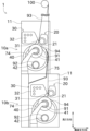
次に、図面を参照して本発明の実施形態を説明する。図1は、本実施形態に係る糸巻取機1の正面図である。図2は、糸巻取機1のブロック図である。以下の説明では、糸の走行方向の上流又は下流を単に上流又は下流と称することがある。
Next, embodiments of the present invention will be described with reference to the drawings. FIG. 1 is a front view of a
図1に示す糸巻取機1の上流には図略の紡糸機が配置されている。紡糸機で製造された糸93は、糸送りローラ100を介して、糸巻取機1に供給される。糸巻取機1は、糸93をボビン91,92に巻き取ってボビン91,92上に糸層を形成しパッケージ94を製造する。糸93は、例えばスパンデックス等の弾性糸である。ただし、糸93の種類はこれに限定されず、例えばナイロン又はポリエステル等の合繊糸であってもよい。
A spinning machine (not shown) is arranged upstream of the
図1に示すように、糸巻取機1は、上段巻取部10aと、下段巻取部10bと、を備える。上段巻取部10a及び下段巻取部10bには、同一の糸送りローラ100からそれぞれ糸93が個別に供給されており、上段巻取部10a及び下段巻取部10bで個別にパッケージ94が製造される。各巻取部10には、パッケージ94の軸方向に並ぶ複数の糸93が供給される。各巻取部10は、複数の糸93をそれぞれ巻き取って、複数のパッケージ94を製造する。
As shown in FIG. 1, the
上段巻取部10a及び下段巻取部10bは、基本的にはそれぞれ同じ装置を備える。そのため、以下では代表して上段巻取部10aについて説明する。図1に示すように、上段巻取部10aは、フレーム11と、第1ハウジング20と、第2ハウジング30と、ターレット板(ボビンホルダ移動機構)40と、を備える。
The upper winding
フレーム11は、上段巻取部10aが備える各部を保持する部材である。第1ハウジング20には、トラバース装置21が取り付けられている。トラバース装置21は、後述するトラバースガイド23が糸93と係合した状態で巻幅方向(パッケージ94の軸方向)に往復動することにより、下流側に送られる糸93をトラバースさせる。図2に示すように、トラバース装置21は、トラバースカム22と、トラバースガイド23と、トラバースモータ24と、を備える。なお、図2は、1つの巻取部(上段巻取部10a又は下段巻取部10b)のブロック図を示している。
The
トラバースカム22は、ボビン91,92と平行に配置されたローラ状の部材である。トラバースカム22の外周面には、螺旋状のカム溝が形成されている。トラバースカム22は、トラバースモータ24により回転駆動される。
The
トラバースガイド23は、糸93と係合する部分である。トラバースガイド23の先端は例えば略U字状のガイド部を有しており、糸93を巻幅方向で挟み込むようにして、糸93と係合する。トラバースガイド23の基端はトラバースカム22のカム溝に位置している。トラバースカム22を回転駆動することで、トラバースガイド23を巻幅方向に往復動させることができる。
The
また、トラバースモータ24は、制御装置50によって制御される。制御装置50は、CPU、ROM、RAM等を備える。CPUは、ROMに記憶されたプログラムをRAMに読み出して実行することにより、上段巻取部10aに関する様々な制御を実行する。
Further, the
第2ハウジング30には、接触ローラ31が回転可能に取り付けられている。接触ローラ31は、糸93の巻取り時において、パッケージ94の糸層に所定の圧力で接触しながら従動回転することにより、パッケージ94の糸層形状を整える。
A
第2ハウジング30には、操作パネル32が設けられている。操作パネル32は、オペレータによって操作される装置である。オペレータは、操作パネル32を操作することにより、上段巻取部10aに対して指示を行う。オペレータが行う指示は、例えば、糸掛けの開始、巻取りの開始、巻取りの停止、巻取条件の変更等である。
The
図2に示すように、上段巻取部10aは、昇降装置60を備える。昇降装置60は、第1ハウジング20及び第2ハウジング30を一体的に昇降させる。具体的には、第1ハウジング20及び第2ハウジング30は、図略の昇降部材に取り付けられている。この昇降部材には、ボールナット61が取り付けられている。また、フレーム11にはネジ棒62が取り付けられている。昇降モータ63を用いてネジ棒62を回転させることにより、第1ハウジング20及び第2ハウジング30を昇降させることができる。昇降モータ63は、制御装置50により制御される。なお、昇降装置60は、ボールネジに代えてシリンダを用いて実現されていてもよい。
As shown in FIG. 2, the upper winding
ターレット板40は、円板状の部材である。ターレット板40は、フレーム11に回転可能に取り付けられている。ターレット板40の回転軸の位置は、ターレット板40の中心位置と一致している。ターレット板40は、図2に示すターレットモータ53により回転駆動される。ターレットモータ53は、制御装置50により制御される。
The
ターレット板40のうち、中心位置を挟んで対向する2箇所には、それぞれ第1ボビンホルダ41と第2ボビンホルダ42が設けられている。第1ボビンホルダ41には、軸方向に並べて複数の第1ボビン91を装着可能である。第2ボビンホルダ42には、軸方向に並べて複数の第2ボビン92を装着可能である。ターレット板40を回転させることにより、第1ボビンホルダ41と第2ボビンホルダ42の位置を変更することができる。なお、第1ボビンホルダ41と第2ボビンホルダ42の位置を変更可能であれば、ターレット板40に代えて別の装置を用いてもよい。
A
第1ボビンホルダ41は、第1ボビンホルダ41の軸位置を回転中心として、ターレット板40に対して回転可能である。第1ボビンホルダ41は、図2に示す第1ボビンホルダモータ54により回転駆動される。同様に、第2ボビンホルダ42は、第2ボビンホルダ42の軸位置を回転中心として、ターレット板40に対して回転可能である。第2ボビンホルダ42は、図2に示す第2ボビンホルダモータ55により回転駆動される。第1ボビンホルダモータ54及び第2ボビンホルダモータ55は、制御装置50により制御される。
The
図1に示すように、第1ボビンホルダ41と第2ボビンホルダ42が上下に並んだ状態において、高い方である第1ボビンホルダ41の第1ボビン91に対して糸93が巻き取られてパッケージ94が製造される。以下では、第1ボビンホルダ41に装着されるボビンを第1ボビン91と称し、第2ボビンホルダ42に装着されるボビンを第2ボビン92と称することがある。
As shown in FIG. 1, when the
また、第1ボビンホルダ41に装着された第1ボビン91に所定量の糸93巻き取ってパッケージ94が満巻となった場合、ターレット板40が回転することにより、第1ボビンホルダ41と第2ボビンホルダ42の位置が切り替わる。その後、満巻となったパッケージ94が回収されつつ、第2ボビンホルダ42に装着された第2ボビン92に対して糸93が巻き取られる。
Further, when the
ボビンホルダ41,42の一方側の端部(ターレット板40側の端部)は、ターレット板40に支持されている。また、糸巻取機1は、パッケージ94を製造するための位置にあるボビンホルダ41,42の他方の端部(ターレット板40とは反対側の端部)を支持する支持部材74を更に備える。
One end of the
図1に示すように、上段巻取部10aのボビンホルダ41,42は、上段巻取部10aのターレット板40が回転することにより、糸送りローラ100から下段巻取部10bに供給される糸93の近傍を通ることになる。また、上段巻取部10aのボビンホルダ41,42上に形成されているパッケージ94の回転により、随伴流が発生する。下段巻取部10bに巻き取られる糸93に随伴流が作用することを抑制するために、上段巻取部10aには防風板75が設けられている。防風板75は、下段巻取部10bには設けられていない。なお、上段巻取部10aから防風板75を省略することもできる。
As shown in FIG. 1, the
次に、糸掛け作業及び捨巻きについて説明する。糸掛け作業とは、パッケージ94の製造の前段階において、オペレータによりボビン91,92に糸93を巻き付ける作業である。捨巻きとは、糸掛け作業後に行われ、巻取り開始時の品質が低い糸93を巻き取る作業である。捨巻きを行って巻き取られた糸93は廃棄される。
Next, threading work and discarded winding will be explained. The threading operation is an operation in which the
糸93の品質が低くなる原因は以下のとおりである。即ち、オペレータによる糸掛けが行われる段階では、トラバースガイド23に糸93が係合されていない状態で糸93が巻き取られる。また、トラバースガイド23は通常よりも低速で駆動している。そのため、糸掛け後に糸93がトラバースガイド23に係合されても、トラバースガイド23が通常の速度となるまでは糸93の品質が低くなる。
The reasons why the quality of the
また、本実施形態では、巻幅方向、パッケージ94の軸方向、及びボビンホルダ41,42の軸方向は全て平行である。以下の説明では、これらの方向を併せて単に「軸方向」と称する。また、糸巻取機1に対して糸送りローラ100が位置する方向を「高さ方向」と称する。特に、高さ方向のうち糸送りローラ100に近い側を上側、その反対側を下側と称する。また、軸方向と高さ方向の両方に直交する方向を「軸直交方向」と称する。
Moreover, in this embodiment, the winding width direction, the axial direction of the
図3には、糸掛け作業及び捨巻きを行ってパッケージ94の製造を開始するまでの処理が記載されている。S1からS7までの処理が糸掛け作業、捨巻き、及びその準備に関する処理である。初めに上段巻取部10aに対してS1からS7までの処理が行われた後に、下段巻取部10bに対してS1からS7までの処理が行われる。以下、S1からS7までの処理を具体的に説明する。
FIG. 3 shows the process from threading and winding to the start of manufacturing the
初めに、オペレータが操作パネル32に所定の第1操作を行う(S1)。第1操作は、糸掛け作業を行うことを糸巻取機1側に通知するための操作である。第1操作は、例えば操作パネル32の所定のボタンを操作することである。
First, an operator performs a predetermined first operation on the operation panel 32 (S1). The first operation is an operation for notifying the
操作パネル32は、第1操作を受けて、糸掛け開始信号を制御装置50に送信する(S2)。糸掛け開始信号は、操作パネル32に第1操作を行うことで制御装置50に送信される電気信号である。糸掛け開始信号は、第1ボビン91に糸を掛けるための信号と称することもできる。
The
制御装置50は、糸掛け開始信号を受けて、ターレットモータ53を制御してターレット板40を反時計回りに回転させることにより、第1ボビンホルダ41を糸掛け位置に合わせる(S3、図5の状態1から状態2)。糸掛け位置とは、オペレータが糸掛け作業を行う際の第1ボビンホルダ41の位置である。
Upon receiving the threading start signal, the
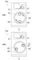
ここで、図4を参照して、ボビンホルダ41,42の各位置について説明する。ボビンホルダ41,42が上下に並んだ状態において、高い方のボビンホルダ41,42の位置が巻取位置であり、低い方のボビンホルダ41,42の位置が待機位置である。糸巻取機1は、巻取位置にあるボビンホルダ41,42のボビン91,92に糸93を巻き取ってパッケージ94を製造する。巻取位置は、ボビンホルダ41,42のボビン91,92又はパッケージ94が接触ローラ31に接触する位置である。また、ターレット板40の回転中心を点Cと称する。点Cを基準(中心)として、ボビンホルダ41,42の位置(詳細にはボビンホルダ41,42の軸の位置)を角度を用いて以下のように表現する。即ち、巻取位置を0°(又は360°)とし、待機位置を180°とする。また、図4に示すように、上段巻取部10aが下段巻取部10bに対して偏位している方向を偏位方向とする。ここでの偏位とは水平面に投影した位置における偏位(言い換えれば平面視における偏位)であり、偏位方向は軸直交方向に平行である。そして、巻取位置から偏位方向に回転する向き(図4の反時計回り)を正とする。本実施形態では、ターレット板40は、反時計回りにのみ、即ち、ボビンホルダ41,42の位置が正方向のみに変更されるように回転する。
Here, each position of the
図4に示すように、本実施形態の糸掛け位置は、270°より大きく360°より小さい位置にある。仮に、糸掛け位置が0°以上180°未満である場合、糸93が接触ローラ31に接触するため、糸掛け作業が失敗する可能性がある。また、糸掛け位置が180°以上270°以下である場合、糸掛け作業の後にターレット板40を反時計回りに回転する際において、糸掛け作業により糸93が巻付けられた第1ボビン91又は捨巻きによる糸層が防風板75に接触する可能性がある(防風板75が無い場合であっても下段巻取部10bの糸道に干渉する可能性がある)。なお、防風板75の軸直交方向の位置を第1ボビン91から離すことにより防風板75との接触を確実に防止できるが、この場合は下段巻取部10bに対する上段巻取部10aの偏位が大きくなるため、糸巻取機1の設置面積が大きくなる。以上の理由により、糸掛け位置は、270°より大きく360°より小さい位置にあることが好ましい。また、ボビンホルダ41,42が支持部材74又は防風板75に近過ぎると糸掛け作業が困難になる可能性がある。更に、ボビンホルダ41,42が接触ローラ31に近い位置であると、糸93と接触ローラ31との接触可能性が生じる。そのため、糸掛け位置は、290°より大きく340°より小さい位置にあることが更に好ましい。本実施形態では、糸掛け位置を300°の位置としている。
As shown in FIG. 4, the threading position in this embodiment is greater than 270° and smaller than 360°. If the threading position is greater than or equal to 0° and less than 180°, the
制御装置50は、ボビンホルダ41を糸掛け位置に合わせた後に、第1ボビンホルダモータ54を制御して第1ボビン91を回転駆動する(S4)。次に、制御装置50は、トラバース装置21を低速駆動する(S5)。トラバース装置21が低速とは、パッケージ94の製造時と比較してトラバース速度が遅いことを示す。
After adjusting the
次に、オペレータは、糸掛け作業を行う(S6)。具体的には、オペレータは、糸送りローラ100に掛かっている複数の糸93をサクションガン等で保持する。そして、オペレータは、保持した複数の糸93を上段巻取部10aのボビンホルダ41に巻き付ける。また、上段巻取部10aには、複数の糸93を間隔を維持して個別に保持する分糸ガイドが設けられている。オペレータは、糸93を分糸ガイドに個別に保持させる。以上により糸掛け作業が完了する。また、第1ボビンホルダ41は既に回転駆動されているため、糸掛け作業が完了することにより、第1ボビンホルダ41に装着されている第1ボビン91に糸93が巻き取られる(捨巻き、S7)。図6の状態3は、糸掛け作業が完了し、捨巻きが行われている状態を示している。その後、下段巻取部10bに対してS1からS7までの処理が行われる。
Next, the operator performs threading work (S6). Specifically, the operator holds the plurality of
上段巻取部10a及び下段巻取部10bに対してS1からS7までの処理が行われた後に、パッケージ94の製造を開始するための処理が行われる。具体的には、図3のS11からS16までの処理が、パッケージ94の製造を開始するための処理に該当する。初めに上段巻取部10aに対してS11からS16までの処理が行われた後に、下段巻取部10bに対してS11からS16までの処理が行われる。以下、S11からS16までの処理を具体的に説明する。
After the processes from S1 to S7 are performed on the upper winding
初めに、オペレータが操作パネル32に所定の第2操作を行う(S11)。第2操作は、パッケージ94の製造を開始することを糸巻取機1側に通知するための操作である。第2操作は、例えば操作パネル32の所定のボタンを操作することである。第1操作と第2操作は同じ操作(例えば、同じボタン操作)であってもよいし、異なる操作(例えば異なるボタン操作)であってもよい。
First, the operator performs a predetermined second operation on the operation panel 32 (S11). The second operation is an operation for notifying the
操作パネル32は、第2操作を受けて、製造開始信号を制御装置50に送信する(S12)。製造開始信号は、操作パネル32に第2操作を行うことで制御装置50に送信される電気信号である。
The
制御装置50は、製造開始信号を受けて、ターレットモータ53を制御してターレット板40を反時計回りに回転させることにより、第1ボビンホルダ41を待機位置に合わせ、第2ボビンホルダ42を巻取位置に合わせる(S13、図6の状態3から図7の状態4)。
Upon receiving the production start signal, the
次に、制御装置50は、ボビンホルダ41の第1ボビン91に巻き取られている糸93が、第2ボビンホルダ42の第2ボビン92に巻き取られるように切り替える(S14、図7の状態5から図8の状態6)。具体的には、第1ボビンホルダ41と第2ボビンホルダ42の間に掛け渡されている糸93に対して、巻付部材81を押し付けて第2ボビン92に対する糸93の巻付け角を大きくして、第2ボビンホルダ42の第2ボビン92に糸93が巻き取られるようにする。このように、一方のボビンホルダ41のボビン91から他方のボビンホルダ42のボビン92に糸93の巻き取りが切り替えられることを糸切替えと称し、本実施形態では、ボビンホルダ41,42が巻取位置及び待機位置にそれぞれ位置しているときに、糸切替えが行われる。即ち、ボビンホルダ41,42がそれぞれ0°,180°の位置が糸切替え位置となっている。前記した製造開始信号は、糸切替え信号でもある。
Next, the
次に、制御装置50は、トラバース装置21を低速駆動から高速駆動に切り替える(S15)。トラバース装置21が高速とは、糸掛け時よりもトラバース速度が速く、かつ、パッケージ94の製造時におけるトラバース速度に一致することである。その後、制御装置50は、昇降モータ63を制御して、トラバース装置21及び接触ローラ31を下降させる(S16、図8の状態7)。これにより、接触ローラ31が第2ボビンホルダ42の第2ボビン92に接触し、パッケージ94の製造が開始される。この後、第2ボビン92のパッケージ94が所定径の満巻のパッケージ94になると、糸切替え信号が発せられて、糸切替えが実施され、ターレット板40が第1ボビンホルダ41の第1ボビン91にパッケージ94が形成されるようになる。なお、この処理の詳細は後述する。以降、満巻のパッケージ94の形成、糸切替え、満巻のパッケージ94と新たなボビン91,92との交換が連続的に繰り返される。
Next, the
また、本実施形態では、第1ボビンホルダ41を糸掛け位置に位置させた後から、第2ボビンホルダ42の第2ボビン92に糸93を巻き取ってパッケージ94を製造する状態になるまでにおいて、ターレット板40をボビンホルダ41,42の位置が正方向のみに変更されるように回転させる。そのため、ターレット板40の制御が単純である。また、ボビンホルダ41は、糸掛け位置から待機位置に到達するまでに防風板75に近接しないので、糸掛け作業により糸93が巻き付けられた第1ボビンホルダ41又は捨巻きの糸層が防風板75に接触することをより確実に抑制できる。更に、本実施形態では、ターレット板40をボビンホルダ41,42の位置が正方向のみに変更するように回転させるとともに、第1ボビンホルダ41と第2ボビンホルダ42とがそれぞれ0°と180°となる位置で糸切替えを行うようにしている。このため、満巻のパッケージ94が防風板75に近接することがなく、このことによっても、下段巻取部10bに対して上段巻取部10aが偏位する量を小さく抑えることができている。
Furthermore, in this embodiment, after the
次に、図4、図9、及び図10を参照して、上記実施形態の変形例を説明する。なお、上記実施形態と本変形例ではターレット板40の制御が異なるだけであり、それ以外の糸巻取機1の構成は同じである。
Next, a modification of the above embodiment will be described with reference to FIGS. 4, 9, and 10. Note that the only difference between the above embodiment and this modification is the control of the
上記実施形態では、糸巻取機1は、糸掛け位置において捨巻きを行う。これに代えて、本変形例では、糸掛け位置と捨巻き位置が異なる。具体的には、図4に示すように、本変形例の捨巻き位置は、120°の位置としている。この捨巻き位置は、0°より大きく180°より小さい位置であればよい。糸掛け位置と捨巻き位置が同じである場合において、捨巻きの時間が長くなったときは糸層が大きくなるため、糸層と防風板75が接触する可能性がある。この点、本変形例の捨巻き位置は、防風板75から離間しているため、糸層と防風板75の接触をより確実に防止できる。なお、本変形例において、捨巻き位置を120°の位置としている理由は、次の理由による。即ち、巻取位置、待機位置、糸切替え位置にてターレット板40が位置決めされるように位置決め機構が設けられているが、これと同様に、糸掛け位置においてもターレット板40が位置決めされるように位置決め機構が設けられている。捨巻き位置を120°の位置とすれば、捨巻き位置がターレット板40の回転中心である点Cを挟んで糸掛け位置の反対位置になり、新たに位置決め機構を設ける必要がなくなるためである。
In the embodiment described above, the
以下、図9及び図10を参照して、本変形例における処理の流れについて説明する。図9のS1からS6の処理は上記実施形態と同じであるため説明を省略する。 The flow of processing in this modification will be described below with reference to FIGS. 9 and 10. The processes from S1 to S6 in FIG. 9 are the same as those in the embodiment described above, and therefore the description thereof will be omitted.
オペレータは、糸掛け作業後に、操作パネル32に所定の第3操作を行う(S7)。第3操作は、糸掛けが完了したことを糸巻取機1側に通知するための操作である。第3操作は、例えば操作パネル32の所定のボタンを操作することである。
After the threading operation, the operator performs a third predetermined operation on the operation panel 32 (S7). The third operation is an operation for notifying the
操作パネル32は、第3操作を受けて、糸掛け完了信号を制御装置50に送信する(S8)。糸掛け完了信号は、操作パネル32に第3操作を行うことで制御装置50に送信される電気信号である。
The
制御装置50は、糸掛け完了信号を受けて、ターレットモータ53を制御してターレット板40を反時計回りに回転させることにより、第1ボビンホルダ41を上述の捨巻き位置に合わせる(S9、図10の状態3Aから状態3B)。これにより、捨巻き位置において捨巻きが継続して行われる(S10)。
Upon receiving the threading completion signal, the
次に、図11から図13を参照して、第2ボビン92に満巻のパッケージ94が形成されて、第1ボビン91に新たに糸93を巻き付ける際の処理について説明する。
Next, with reference to FIGS. 11 to 13, a description will be given of a process when a fully wound
第2ボビン92に満巻のパッケージ94が形成された場合、制御装置50は、ターレットモータ53を制御してターレット板40を反時計回りに回転させることにより、第1ボビンホルダ41を第1切替位置に合わせ、第2ボビンホルダ42を第2切替位置に合わせる(図11の状態Aから図12の状態B)。ここで、第1切替位置と第2切替位置は、糸93を巻き取るボビン91,92を切り替えるときのボビン91,92の位置である。詳細には、第1切替位置とは、新たに糸93の巻取りを開始するボビン(言い換えれば、糸93が巻かれていないボビン、第1ボビン91)の位置である。第2切替位置とは、満巻となったパッケージ94のボビン(第2ボビン92)の位置である。なお、第1切替位置の好ましい角度範囲は後述する。
When a fully wound
次に、制御装置50は、第2ボビン92(パッケージ94)に巻き取られている糸93が、第1ボビン91に巻き取られるように切り替える(図12の状態Cから図13の状態D)。具体的な処理は、上述した捨巻き時の糸切替えと同じである。また、第2ボビン92の満巻のパッケージ94は、第2ボビンホルダ42から抜き取られ、第2ボビンホルダ42に新たな第2ボビン92(糸93が巻かれていない第2ボビン92)が装着される。また、第2ボビン92に満巻のパッケージ94が形成されて、第1ボビン91に新たに糸93を巻き付けるまでの間において、ターレット板40は同一方向(正方向)のみに回転する。
Next, the
次に、制御装置50は、昇降モータ63を制御して、トラバース装置21及び接触ローラ31を下降させる(図13の状態E)。これにより、接触ローラ31が第1ボビン91に接触し、パッケージ94の製造が開始される。
Next, the
次に、図14を参照して、第1切替位置の好ましい角度範囲について説明する。 Next, a preferable angular range of the first switching position will be described with reference to FIG. 14.
図14に示すように、第1切替位置は、0°を基準として±45°未満の位置であることが好ましい。仮に、第1切替位置が45°以上180°以下である場合、第2切替位置が210°以上360°以下に位置するため、満巻のパッケージ94が下段巻取部10bへの糸道に近接する。そのため、満巻のパッケージ94と糸道の干渉を防止するために、下段巻取部10bに対する上段巻取部10aの偏位が大きくなるため、糸巻取機1の設置面積が大きくなる。従って、第1切替位置が45°以上180°以下であることは好ましくない。
As shown in FIG. 14, the first switching position is preferably a position less than ±45° with respect to 0°. If the first switching position is 45° or more and 180° or less, the second switching position is 210° or more and 360° or less, so the fully wound
また、第1切替位置が180°以上315°以下である場合、満巻のパッケージ94に繋がっている糸93を第1ボビン91に巻き付けることが困難になる。従って、第1切替位置が180°以上315°以下であることは好ましくない。
Furthermore, if the first switching position is greater than or equal to 180 degrees and less than or equal to 315 degrees, it becomes difficult to wind the
以上により、第1切替位置は、0°を基準として±45°未満の位置であることが好ましい。また、第1切替位置が0°ではない場合、制御装置50は、第2ボビン92に巻き取られている糸93が第1ボビン91に巻き取られるように切り替えた後に、ターレットモータ53を制御してターレット板40を回転させることにより、第1ボビンホルダ41の位置を0°の位置(巻取位置)に合わせる制御を行う。つまり、第1切替位置が315°より大きく360°より小さい場合、制御装置50は、上記の切替後に、ターレット板40を反時計回り(正方向)に回転させる。一方、第1切替位置が0°より大きく45°より小さい場合、制御装置50は、上記の切替後に、ターレット板40を時計回り(逆方向)に回転させる。その後、上段巻取部10aは、第1ボビン91に糸93を巻き取って、パッケージ94を製造する。
Based on the above, the first switching position is preferably a position less than ±45° with respect to 0°. Further, when the first switching position is not 0°, the
以上に説明したように、本実施形態の糸巻取機1は、下段巻取部10bと、上段巻取部10aと、を備える。下段巻取部10bは、糸送りローラ100から送り出された糸93を巻き取ってパッケージ94を製造する。上段巻取部10aは、下段巻取部10bより高い位置であって、平面視において下段巻取部10bよりもパッケージ94の軸方向と垂直な方向に偏位した位置に配置され、糸送りローラ100から送り出された糸93を巻き取ってパッケージ94を製造する。上段巻取部10aは、第1ボビンホルダ41と、第2ボビンホルダ42と、ターレット板40と、接触ローラ31と、を備える。第1ボビンホルダ41は、第1ボビン91を保持する。第2ボビンホルダ42は、第2ボビン92を保持する。ターレット板40は、第1ボビンホルダ41及び第2ボビンホルダ42が取り付けられており、パッケージ94の軸方向と平行な回転軸を中心として回転することで、第1ボビンホルダ41及び第2ボビンホルダ42の位置を変更する。接触ローラ31は、パッケージ94の製造時に第1ボビン91、第2ボビン92、又はパッケージ94に接触して回転する。ターレット板40が第1ボビンホルダ41又は第2ボビンホルダ42を保持する位置に関して、第1ボビン91、第2ボビン92、又はパッケージ94が接触ローラ31に接触して第1ボビン91又は第2ボビン92に糸93を巻き取ってパッケージ94を製造するときの位置を0°又は360°とし、0°から上段巻取部10aが下段巻取部10bに対して偏位している方向に回転する向きを正としたときに、ターレット板40は、第1ボビン91に糸93を掛けるための信号(糸掛け開始信号)を受けて、第1ボビンホルダ41の位置を270°より大きく360°より小さい位置に合わせる。
As described above, the
これにより、下段巻取部10bに対して上段巻取部10aが偏位する量を小さく抑えることができ、糸巻取機1の設置面積を小さく抑えることができる。
Thereby, the amount by which the upper winding
本実施形態の糸巻取機1において、ターレット板40は、第1ボビン91に糸93を掛けるための信号を受けて、第1ボビンホルダ41の位置を290°より大きく340°より小さい位置に合わせる。
In the
これにより、下段巻取部10bの糸道から一層遠い位置で、かつ、糸93と接触ローラ31との接触可能性をより回避した位置で、上段巻取部の糸掛けを行うことができる。
Thereby, threading of the upper winding section can be carried out at a position further from the yarn path of the lower winding
本実施形態の糸巻取機1において、ターレット板40は、第1ボビン91に糸93が巻かれている場合に、その糸93が第2ボビン92に巻かれるように、又は、第2ボビン92に糸93が巻かれている場合に、その糸93が第1ボビン91に巻かれるように、糸切替えを行うための信号(糸切替え信号)を受けて、第1ボビンホルダ41及び第2ボビンホルダ42の一方の位置を180°に合わせ、かつ、他方の位置を0°に合わせる。
In the
これにより、第1ボビン91に糸93を掛けた後、第1ボビン91に巻かれている糸93を第2ボビン92に巻き付けるようにする糸切替え、又は、パッケージ94の製造開始後に満巻のパッケージ94の第1ボビン91又は第2ボビン92に巻かれている糸93を、糸93が巻かれていない第2ボビン92又は第1ボビン91に巻き付けるようにする糸切替えを行うときに、第1ボビン91及び第2ボビン92を下段巻取部10bの糸道から遠い位置にして、糸切替えを行うことができる。
As a result, after the
本実施形態の糸巻取機1において、第1ボビン91に糸93を掛ける状態から、第2ボビン92に糸93を巻き取ってパッケージ94を製造する状態になるまでにおいて、ターレット板40は、第1ボビンホルダ41及び第2ボビンホルダ42の位置が正方向のみに変更されるように回転する。
In the
ターレット板40の制御を単純にすることができる。また、捨巻きにより糸層が形成された第1ボビン91が下段巻取部10bの糸道に近い側を通過しないため、偏位量を小さくできる。
Control of the
本実施形態の糸巻取機1において、第1ボビン91に糸93を掛けるための信号を受けて、第1ボビンホルダ41の位置を270°より大きく360°より小さい位置に合わせた後に、第1ボビン91に糸93を掛ける作業が完了したことを示す信号(糸掛け完了信号)を受けて、第1ボビンホルダ41の位置を0°より大きく180°より小さい位置に合わせる。
In the
これにより、第1ボビン91が270°より大きく360°より小さい位置で巻き太ることを抑制できるので、第1ボビン91又はその糸層が下段巻取部10bの糸道に干渉しにくい。
This makes it possible to prevent the
本実施形態の糸巻取機1において、上段巻取部10aは、第1ボビンホルダ41又は第2ボビンホルダ42に形成されているパッケージ94の回転によって発生する随伴流が下段巻取部10bで巻き取られる糸93に作用することを抑制する防風板75を備える。
In the
防風板75を設けることにより、随伴流が糸93に及ぼす影響を軽減できる。
By providing the
本実施形態の糸巻取機1において、ターレット板40は、第2ボビン92に形成されたパッケージ94が満巻となった場合に、第1ボビンホルダ41の位置を0°を基準として±45°未満の位置に合わせた状態で、第2ボビン92に巻き取られている糸93が第1ボビン91に巻き取られるように切り替える。
In the
これにより、満巻のパッケージ94が、下段巻取部10bへの糸道に近い範囲を通らない。そのため、上段巻取部10aが偏位する量を更に小さく抑えることができる。また、パッケージ94に繋がる糸93を第1ボビン91に巻き付かせる作業を容易に行うことができる。
As a result, the fully wound
以上に本発明の好適な実施の形態を説明したが、上記の構成は例えば以下のように変更することができる。 Although the preferred embodiments of the present invention have been described above, the above configuration can be modified as follows, for example.
上記実施形態のトラバース装置21はカムドラム式であるが、トラバースガイド23を巻幅方向に往復動させることが可能であれば異なる構成であってもよい。例えば、トラバース装置21に代えて、ベルト式のトラバース装置を用いることもできる。
Although the
上記実施形態及び変形例で示した処理図は一例であり、一部の処理を省略したり、一部の処理の内容を変更したり、新たな処理を追加したりしてもよい。 The process diagrams shown in the above embodiments and modifications are examples, and some processes may be omitted, the contents of some processes may be changed, or new processes may be added.
1 糸巻取機
10a 上段巻取部
10b 下段巻取部
21 トラバース装置
31 接触ローラ
40 ターレット板(ボビンホルダ移動機構)
41 第1ボビンホルダ
42 第2ボビンホルダ
50 制御装置
91 第1ボビン
92 第2ボビン
93 糸
94 パッケージ
100 糸送りローラ
1
41
Claims (7)
前記下段巻取部より高い位置であって、平面視において前記下段巻取部よりも前記パッケージの軸方向と垂直な方向に偏位した位置に配置され、前記糸送りローラから送り出された糸を巻き取って前記パッケージを製造する上段巻取部と、
を備え、
前記上段巻取部は、
第1ボビンを保持する第1ボビンホルダと、
第2ボビンを保持する第2ボビンホルダと、
前記第1ボビンホルダ及び前記第2ボビンホルダが取り付けられており、前記パッケージの軸方向と平行な回転軸を中心として回転することで、前記第1ボビンホルダ及び前記第2ボビンホルダの位置を変更するボビンホルダ移動機構と、
前記パッケージの製造時に前記第1ボビン、前記第2ボビン、又は前記パッケージに接触して回転する接触ローラと、
を備え、
前記ボビンホルダ移動機構が前記第1ボビンホルダ又は前記第2ボビンホルダを保持する位置に関して、前記第1ボビン、前記第2ボビン、又は前記パッケージが前記接触ローラに接触して前記第1ボビン又は前記第2ボビンに糸を巻き取って前記パッケージを製造するときの位置を0°又は360°とし、0°から前記上段巻取部が前記下段巻取部に対して偏位している方向に回転する向きを正としたときに、
前記ボビンホルダ移動機構は、前記第1ボビンに糸を掛けるための信号を受けて、前記第1ボビンホルダの位置を270°より大きく360°より小さい位置に合わせることを特徴とする糸巻取機。 a lower winding section that winds up the yarn sent out from the yarn feeding roller to manufacture a package;
The yarn feeding roller is disposed at a position higher than the lower winding section and is offset from the lower winding section in a direction perpendicular to the axial direction of the package in a plan view, and is arranged to carry the yarn sent out from the yarn feeding roller. an upper winding section that winds up to manufacture the package;
Equipped with
The upper winding section is
a first bobbin holder that holds a first bobbin;
a second bobbin holder that holds a second bobbin;
The first bobbin holder and the second bobbin holder are attached, and a bobbin holder moving mechanism changes the positions of the first bobbin holder and the second bobbin holder by rotating around a rotation axis parallel to the axial direction of the package. and,
a contact roller that rotates in contact with the first bobbin, the second bobbin, or the package during manufacturing of the package;
Equipped with
Regarding the position where the bobbin holder moving mechanism holds the first bobbin holder or the second bobbin holder, the first bobbin, the second bobbin, or the package contacts the contact roller and moves the first bobbin or the second bobbin. The position at which the package is manufactured by winding the thread is defined as 0° or 360°, and the direction in which the upper winding section rotates from 0° in a direction that is offset from the lower winding section is defined as When it is correct,
The yarn winding machine is characterized in that the bobbin holder moving mechanism adjusts the position of the first bobbin holder to a position greater than 270 degrees and less than 360 degrees upon receiving a signal for threading the first bobbin.
前記ボビンホルダ移動機構は、前記第1ボビンに糸を掛けるための信号を受けて、前記第1ボビンホルダの位置を290°より大きく340°より小さい位置に合わせることを特徴とする糸巻取機。 The yarn winding machine according to claim 1,
The yarn winding machine is characterized in that the bobbin holder moving mechanism adjusts the position of the first bobbin holder to a position greater than 290 degrees and less than 340 degrees upon receiving a signal for threading the first bobbin.
前記ボビンホルダ移動機構は、前記第1ボビンに糸が巻かれている場合に、その糸が前記第2ボビンに巻かれるように、又は、前記第2ボビンに糸が巻かれている場合に、その糸が前記第1ボビンに巻かれるように、糸切替えを行うための信号を受けて、第1ボビンホルダ及び第2ボビンホルダの一方の位置を180°に合わせ、かつ、他方の位置を0°に合わせることを特徴とする糸巻取機。 The yarn winding machine according to claim 1 or 2,
The bobbin holder moving mechanism is arranged so that when a thread is wound on the first bobbin, the thread is wound on the second bobbin, or when a thread is wound on the second bobbin, the thread is wound on the second bobbin. Upon receiving a signal for switching the thread so that the thread is wound on the first bobbin, one of the first bobbin holder and the second bobbin holder is adjusted to 180°, and the other is adjusted to 0°. A thread winding machine characterized by:
前記第1ボビンに糸を掛ける状態から、前記第2ボビンに糸を巻き取ってパッケージを製造する状態になるまでにおいて、前記ボビンホルダ移動機構は、前記第1ボビンホルダ及び前記第2ボビンホルダの位置が正方向のみに変更されるように回転することを特徴とする糸巻取機。 A thread winding machine according to any one of claims 1 to 3,
The bobbin holder moving mechanism ensures that the positions of the first bobbin holder and the second bobbin holder are correct from the state where the thread is hung on the first bobbin to the state where the thread is wound onto the second bobbin to manufacture a package. A yarn winding machine characterized in that it rotates so that only the direction is changed.
前記ボビンホルダ移動機構は、
前記第1ボビンに糸を掛けるための信号を受けて、前記第1ボビンホルダの位置を270°より大きく360°より小さい位置に合わせた後に、
前記第1ボビンに糸を掛ける作業が完了したことを示す信号を受けて、前記第1ボビンホルダの位置を0°より大きく180°より小さい位置に合わせることを特徴とする糸巻取機。 A yarn winding machine according to any one of claims 1 to 4,
The bobbin holder moving mechanism is
After receiving a signal for threading the first bobbin and adjusting the position of the first bobbin holder to a position greater than 270° and smaller than 360°,
A thread winding machine characterized in that the first bobbin holder is adjusted to a position greater than 0° and smaller than 180° upon receiving a signal indicating that the work of threading the first bobbin has been completed.
前記上段巻取部は、前記第1ボビンホルダ又は前記第2ボビンホルダに形成されている前記パッケージの回転によって発生する随伴流が前記下段巻取部で巻き取られる糸に作用することを抑制する防風板を備えることを特徴とする糸巻取機。 A thread winding machine according to any one of claims 1 to 5,
The upper winding section includes a windbreak plate that suppresses the accompanying flow generated by the rotation of the package formed in the first bobbin holder or the second bobbin holder from acting on the yarn wound in the lower winding section. A yarn winding machine characterized by comprising:
前記ボビンホルダ移動機構は、前記第2ボビンに形成された前記パッケージが満巻となった場合に、前記第1ボビンホルダの位置を0°を基準として±45°未満の位置に合わせた状態で、前記第2ボビンに巻き取られている糸が前記第1ボビンに巻き取られるように切り替えることを特徴とする糸巻取機。 A yarn winding machine according to any one of claims 1 to 6,
When the package formed on the second bobbin is fully wound, the bobbin holder moving mechanism moves the first bobbin holder to a position less than ±45° with respect to 0°. A yarn winding machine characterized in that the yarn being wound on the second bobbin is switched so that the yarn is wound on the first bobbin.
Applications Claiming Priority (2)
| Application Number | Priority Date | Filing Date | Title |
|---|---|---|---|
| JP2022049589 | 2022-03-25 | ||
| JP2022049589 | 2022-03-25 |
Publications (1)
| Publication Number | Publication Date |
|---|---|
| JP2023143807A true JP2023143807A (en) | 2023-10-06 |
Family
ID=85724990
Family Applications (1)
| Application Number | Title | Priority Date | Filing Date |
|---|---|---|---|
| JP2023042480A Pending JP2023143807A (en) | 2022-03-25 | 2023-03-17 | Yarn winding machine |
Country Status (4)
| Country | Link |
|---|---|
| EP (1) | EP4249414A1 (en) |
| JP (1) | JP2023143807A (en) |
| KR (1) | KR20230139318A (en) |
| CN (1) | CN116803880A (en) |
Family Cites Families (5)
| Publication number | Priority date | Publication date | Assignee | Title |
|---|---|---|---|---|
| US6015113A (en) * | 1997-10-06 | 2000-01-18 | E. I. Du Pont De Nemours And Company | Winder for synthetic filaments |
| JPH11193183A (en) * | 1997-12-29 | 1999-07-21 | Murata Mach Ltd | Spinning winding machine for elastic yarn and elastic yarn package |
| JP3440839B2 (en) * | 1998-09-11 | 2003-08-25 | 村田機械株式会社 | Threading method of spinning winder |
| JP3303850B2 (en) | 1999-07-01 | 2002-07-22 | 村田機械株式会社 | Spinning winder and bunch winding method thereof |
| JP2012144323A (en) * | 2011-01-11 | 2012-08-02 | Tmt Machinery Inc | Spun yarn winding device and spun yarn winding facility |
-
2023
- 2023-03-14 KR KR1020230033204A patent/KR20230139318A/en unknown
- 2023-03-17 JP JP2023042480A patent/JP2023143807A/en active Pending
- 2023-03-21 EP EP23163013.8A patent/EP4249414A1/en active Pending
- 2023-03-24 CN CN202310300715.8A patent/CN116803880A/en active Pending
Also Published As
| Publication number | Publication date |
|---|---|
| CN116803880A (en) | 2023-09-26 |
| EP4249414A1 (en) | 2023-09-27 |
| KR20230139318A (en) | 2023-10-05 |
Similar Documents
| Publication | Publication Date | Title |
|---|---|---|
| JP5615743B2 (en) | Spinning winder | |
| JP2003238031A (en) | Revolving automatic winder | |
| CN101331078B (en) | Method and machine for winding threads continuously preceding | |
| JP2016044079A (en) | Method for operating operation unit of fiber machine producing string wound package and operation unit belonging to it | |
| WO2004026746A1 (en) | Traverse motion device | |
| CN109641713B (en) | Control method of winding machine and winding machine | |
| CN102530640B (en) | Yarn winding device | |
| WO2004018340A1 (en) | Revolving type thread winding machine | |
| JPH11193179A (en) | Winding method of spinning winding machine | |
| EP3363756B1 (en) | Yarn winder | |
| JP2023143807A (en) | Yarn winding machine | |
| JP4612673B2 (en) | Winding device | |
| CN101423156B (en) | Yarn guide device of revolving type automatic winder | |
| JP6337569B2 (en) | Yarn winding device and yarn winding method | |
| JP2023135874A (en) | Yarn winder | |
| JP2008522926A (en) | Winder | |
| JP2000128435A (en) | Winder and winding method for synthetic fiber | |
| JP4590156B2 (en) | Elastic fiber winder | |
| JP2000185872A (en) | Control method for thread line winder | |
| JP2007269494A (en) | Winding device for bundle of fibers and producing method for package of bundle of fibers | |
| JP2024038600A (en) | Yarn winding machine | |
| JPH10273268A (en) | Thread switching method for turret type thread winder | |
| JP2016508473A (en) | Winder | |
| KR20230133192A (en) | Yarn Winding Machine | |
| JP2022085641A (en) | Yarn winding machine |