JP2023127146A - liquid discharge head - Google Patents
liquid discharge head Download PDFInfo
- Publication number
- JP2023127146A JP2023127146A JP2022030748A JP2022030748A JP2023127146A JP 2023127146 A JP2023127146 A JP 2023127146A JP 2022030748 A JP2022030748 A JP 2022030748A JP 2022030748 A JP2022030748 A JP 2022030748A JP 2023127146 A JP2023127146 A JP 2023127146A
- Authority
- JP
- Japan
- Prior art keywords
- convex portion
- substrate
- ejection head
- liquid ejection
- head according
- Prior art date
- Legal status (The legal status is an assumption and is not a legal conclusion. Google has not performed a legal analysis and makes no representation as to the accuracy of the status listed.)
- Pending
Links
- 239000007788 liquid Substances 0.000 title claims abstract description 70
- 239000000758 substrate Substances 0.000 claims abstract description 111
- 239000000853 adhesive Substances 0.000 claims abstract description 43
- 230000001070 adhesive effect Effects 0.000 claims abstract description 43
- 238000010586 diagram Methods 0.000 description 64
- 239000011800 void material Substances 0.000 description 50
- 229920002120 photoresistant polymer Polymers 0.000 description 21
- 238000005530 etching Methods 0.000 description 17
- 238000004519 manufacturing process Methods 0.000 description 16
- 230000000694 effects Effects 0.000 description 14
- 238000000034 method Methods 0.000 description 12
- 239000012790 adhesive layer Substances 0.000 description 7
- 239000000976 ink Substances 0.000 description 6
- 238000001312 dry etching Methods 0.000 description 5
- 238000001039 wet etching Methods 0.000 description 4
- 230000008602 contraction Effects 0.000 description 3
- 238000005520 cutting process Methods 0.000 description 2
- 238000010438 heat treatment Methods 0.000 description 2
- 238000005304 joining Methods 0.000 description 2
- 239000010410 layer Substances 0.000 description 2
- 239000002184 metal Substances 0.000 description 2
- 238000000059 patterning Methods 0.000 description 2
- 239000011347 resin Substances 0.000 description 2
- 229920005989 resin Polymers 0.000 description 2
- 238000009623 Bosch process Methods 0.000 description 1
- XUIMIQQOPSSXEZ-UHFFFAOYSA-N Silicon Chemical compound [Si] XUIMIQQOPSSXEZ-UHFFFAOYSA-N 0.000 description 1
- 239000003086 colorant Substances 0.000 description 1
- 238000004891 communication Methods 0.000 description 1
- 238000007599 discharging Methods 0.000 description 1
- 238000001125 extrusion Methods 0.000 description 1
- 238000009434 installation Methods 0.000 description 1
- 230000007257 malfunction Effects 0.000 description 1
- 239000000463 material Substances 0.000 description 1
- 230000002093 peripheral effect Effects 0.000 description 1
- 239000003566 sealing material Substances 0.000 description 1
- 229910052710 silicon Inorganic materials 0.000 description 1
- 239000010703 silicon Substances 0.000 description 1
Images


Landscapes
- Particle Formation And Scattering Control In Inkjet Printers (AREA)
Abstract
Description
本発明は、複数の基板から成る液体吐出ヘッドに関する。 The present invention relates to a liquid ejection head made up of a plurality of substrates.
紙等の記録媒体に液体を吐出して記録を行う記録装置は、液体を吐出する吐出口や、吐出のための圧力を発生する圧力発生素子を備える液体吐出ヘッドを有する。液体吐出ヘッドは、接着剤を用いて複数の基板を接合することで形成されることがある。その代表例としては、圧電素子を駆動して液体を吐出するピエゾヘッド方式がある。 2. Description of the Related Art A printing apparatus that performs printing by ejecting liquid onto a recording medium such as paper has a liquid ejection head that includes an ejection port that ejects liquid and a pressure generating element that generates pressure for ejection. A liquid ejection head is sometimes formed by bonding a plurality of substrates together using an adhesive. A typical example is a piezo head method that drives a piezoelectric element to eject liquid.
複数の基板を接着剤により接合する際に重要な事は、基板―基板間に形成される接着剤層に空洞(接着剤が塗布されていない領域。以下、ボイドと称する)が無いことである。もし接着剤層にボイドがあると、接着剤自体の熱収縮や基板内外の圧力差などの様々な要因によってそのボイドが拡大した場合、液体が通り抜ける空間と成り得てしまう。即ち、本来接着剤が形成されているべき領域に液体流路が形成されてしまう。液体吐出ヘッドにおいて接着剤が形成される領域は、異なる色の液体(インク)が流れる流路同士を隔てたりする為に必要な領域である。したがって、この領域を液体が流れる場合、機能上もしくは品質上の弊害が生じる。 When bonding multiple substrates with adhesive, it is important that there are no cavities (areas where no adhesive is applied, hereinafter referred to as voids) in the adhesive layer formed between the substrates. . If there is a void in the adhesive layer, if the void expands due to various factors such as thermal contraction of the adhesive itself or a pressure difference between the inside and outside of the substrate, it can become a space through which liquid can pass. That is, a liquid flow path is formed in a region where an adhesive should originally be formed. The area in which the adhesive is formed in the liquid ejection head is an area necessary for separating channels through which liquids (inks) of different colors flow. Therefore, if liquid flows through this area, there will be functional or quality problems.
特許文献1では、基板に凸部を形成することで、ボイドの拡大を抑制する方法を開示している。接着剤層中のボイド拡大が進行すると、ボイドが凸部に衝突し、それ以上のボイドの拡大が阻害される。換言すれば、ボイドの拡大を凸部で堰き止めることができる。
特許文献1の方法では、接合する基板のうち片方の基板にのみ凸部を形成している。そのため、凸部が形成されていない基板側にボイドが生じた場合には、ボイドが拡大してしまう恐れがある。図1を用いて詳しく説明する。図1は、凸部7が形成された第1の基板1および凸部が形成されていない第2の基板17を接着剤3により接合している様子を示す概略図である。図1(a)に示すように、凸部が形成されていない第2の基板17側にボイド2が発生している。この状態でボイド2が拡大すると、ボイド2の進行方向には進行を堰き止めるための障害物がないため、図1(b)、(c)に示すように、ボイド2は流路4へと拡大し、流路4とボイド2は連通してしまう。ボイドの拡大方向を矢印13で示している。その結果、流路4を流動する液体は拡大したボイド5に流れ込んでしまい、機能上もしくは品質上の弊害が生じる。
In the method of
本発明は上記課題を鑑み、ボイドの拡大をより抑制することができる液体吐出ヘッドを提供することを目的とする。 In view of the above problems, an object of the present invention is to provide a liquid ejection head that can further suppress the expansion of voids.
上記課題を解決するために本発明は、第1の面を有する第1の基板と、前記第1の面と対向する第2の面を有する第2の基板と、を備え、前記第1の面と前記第2の面との間にある接着剤を介して前記第1の基板と前記第2の基板とが接合されている液体吐出ヘッドにおいて、前記第1の面には、前記第2の面に向かって突出する第1の凸部が形成されており、前記第2の面には、前記第1の面に向かって突出する第2の凸部が形成されていることを特徴とする。 In order to solve the above problems, the present invention includes a first substrate having a first surface and a second substrate having a second surface opposite to the first surface, In the liquid ejection head in which the first substrate and the second substrate are bonded to each other via an adhesive between the first surface and the second surface, the first surface has the second substrate. A first protrusion protruding toward the surface is formed, and a second protrusion protruding toward the first surface is formed on the second surface. do.
本発明によれば、ボイドの拡大をより抑制することができる液体吐出ヘッドを提供することができる。 According to the present invention, it is possible to provide a liquid ejection head that can further suppress the expansion of voids.
以下に、本発明の好ましい実施形態を添付の図面に基づいて詳細に説明する。なお、各図において、同一の部材については同一の参照番号を付し、重複する説明は省略する。 Hereinafter, preferred embodiments of the present invention will be described in detail based on the accompanying drawings. In addition, in each figure, the same reference number is attached|subjected about the same member, and the overlapping description is abbreviate|omitted.
(第1の実施形態)
本実施形態の液体吐出ヘッドは、インクジェットプリンター(不図示)に搭載される。インクジェットプリンターには様々な形態があるが、一般的にはプリンターには走査方向に移動可能なキャリッジ(不図示)が設けられ、キャリッジには、インクを印刷媒体上に吐出する液体吐出ヘッドが設けられている。インクはインクタンクから液体流路を通り、液体吐出ヘッドに設けられた吐出口から印字対象物に吐出される。キャリッジの走査と吐出を繰り返す事で、所望のパターンが印字される。
(First embodiment)
The liquid ejection head of this embodiment is installed in an inkjet printer (not shown). There are various types of inkjet printers, but printers are generally equipped with a carriage (not shown) that can move in the scanning direction, and the carriage is equipped with a liquid ejection head that ejects ink onto the print medium. It is being Ink passes through a liquid flow path from an ink tank and is ejected onto a printing target from an ejection port provided in a liquid ejection head. A desired pattern is printed by repeating carriage scanning and ejection.
図2は、圧電素子19を含む複数の基板を接着剤で接合することで形成された本実施形態の液体吐出ヘッド21を示す概略図である。図2(a)は、液体吐出ヘッド21の斜視図である。図2(b)は、図2(a)に示すU―U´線における断面図である。図2(c)は、図2(b)に示す破線で囲んだ領域の拡大図である。液体吐出ヘッド21は、第1の基板1、第2の基板17および第3の基板22から構成されている。第1の基板1には、液体が流動する流路4が形成されている。第2の基板17には、圧電素子19や流路4が形成されている。第3の基板22には、紙などの対象物に液体を吐出する為の吐出口18が形成されている。第1の基板1、第2の基板17および第3の基板22は、接着剤3を介してそれぞれ接合されている。接着剤3は、第1の基板1の第1の面23と、第1の面23と対向する第2の面24との間に塗布されている。図2(c)に示すように、第1の基板1には凸部7(第1の凸部7とも称す)、第2の基板17には第2の凸部8がそれぞれ形成されている。第1の凸部7は、第2の面24に向かって突出しており、第2の凸部8は、第1の面23に向かって突出している。
FIG. 2 is a schematic diagram showing a
図3は、図2(c)に示す断面図を用いて本実施形態の効果を説明する概略図である。ボイド2が拡大する過程を示している。第1の基板1と第2の基板17との間の接着剤3の層の一部にはボイド2が存在している。接着剤3を硬化させる為の加熱等を行う事による収縮や左右の空間の圧力差などの様々な要因によって、ボイド2は矢印13に従って拡がっていく(図3(a))。ボイド2は、第2の凸部8とぶつかることで、ボイド2は図面左方向から図面下方向に進行方向が変化する(図3(b))。その後、ボイド2は第1の基板1の表面まで到達すると再び左方向に進行する(図3(c))。しかし、それまでの間に接着剤3の硬化が進行していき、ボイド2が流路4まで進行する前に接着剤3の硬化が完了する。
FIG. 3 is a schematic diagram illustrating the effects of this embodiment using the cross-sectional view shown in FIG. 2(c). It shows the process in which
したがって、本実施形態においては、接合する2つの基板のそれぞれに凸部を設けることでボイド2の進行の距離を稼ぐ。これにより、ボイド2の拡大をより抑制することができる。また、2つの基板それぞれに凸部が形成されていることにより、ボイド2が第1の基板側もしくは第2の基板側のどちらに生じていたとしても、第1の凸部7または第2の凸部8のどちらかには必ずボイド2が衝突することになる。よって、ボイド2の拡大をより抑制することができる。ボイド2が拡大すると、流路4内の液体が圧電素子19に付着し、圧電素子19が故障する可能性もある。本実施形態によれば、圧電素子19等の故障も抑制することができる。
Therefore, in this embodiment, by providing a convex portion on each of the two substrates to be joined, the distance over which the
図4(a)は、第1の凸部7周りの第1の基板1の上面図である。図4(b)は、図4(a)に示すA-A´線の断面図である。図4は、接着剤3を省略して図示している。また、説明のため、第2の凸部8も図示している。第1の凸部7および第2の凸部8の高さは略同じである。第1の凸部7、第2の凸部8はどちらが内側(流路4側)、外側でも良いが、ボイド2が生じやすい場所が第1の凸部7と第2の凸部8の間には来ないような位置に形成する事が必要である。また、より大きな効果を得る為には、第1の凸部7と第2の凸部8の一部が上下方向に対して一定量以上重なっている事が好ましく、第1の凸部7と第2の凸部8の高さの合計は接着層の高さ(厚さ)以上である事が好ましい。図4(a)に示すように、第1の凸部7および第2の凸部8は、流路4の開口を連続的に囲んでいる。これにより、どの箇所にボイド2が生じたとしても、ボイド2が流路まで拡大することを抑制することができる。
FIG. 4A is a top view of the
(第2の実施形態)
第2の実施形態について説明する。第1の実施形態の同様の箇所については同一の符号を付し、説明は省略する。図5(a)は、図4(a)に対応する本実施形態の図である。図5(b)は、図4(b)に対応する本実施形態の図である。本実施形態においては、第1の凸部7および第2の凸部8の側面が湾曲していることを特徴とする。これにより、第1の凸部7、第2の凸部8の表面積を大きくすることができ、ボイド2の進行の距離をより確保することができる。よって、ボイド2の拡大をより抑制することができる。
(Second embodiment)
A second embodiment will be described. The same reference numerals are given to the same parts in the first embodiment, and the description thereof will be omitted. FIG. 5(a) is a diagram of this embodiment corresponding to FIG. 4(a). FIG. 5(b) is a diagram of this embodiment corresponding to FIG. 4(b). This embodiment is characterized in that the side surfaces of the first
(第3の実施形態)
第3の実施形態について説明する。第1の実施形態の同様の箇所については同一の符号を付し、説明は省略する。図6(a)は、図4(a)に対応する本実施形態の図である。図6(b)は、図4(b)に対応する本実施形態の図である。第1の実施形態とは異なり、第1の凸部7、第2の凸部8の高さが異なっている。第1の凸部7、第2の凸部8はどちらが高く、どちらが低くても良いが、ボイド2が生じやすい場所の近傍に高い方の凸部を設けると本発明の効果をより高める事が出来る。また、第3の実施形態においても、より大きな効果を得る為には第1の凸部7と第2の凸部8の一部が上下方向に対して一定量以上重なっている事が好ましく、第1の凸部7と第2の凸部8の高さの合計は接着層の高さ以上である事が好ましい。
(Third embodiment)
A third embodiment will be described. The same reference numerals are given to the same parts in the first embodiment, and the description thereof will be omitted. FIG. 6(a) is a diagram of this embodiment corresponding to FIG. 4(a). FIG. 6(b) is a diagram of this embodiment corresponding to FIG. 4(b). Unlike the first embodiment, the heights of the first
(第4の実施形態)
第4の実施形態について説明する。第1の実施形態の同様の箇所については同一の符号を付し、説明は省略する。図7(a)は、図4(a)に対応する本実施形態の図である。図7(b)は、図4(b)に対応する本実施形態の図である。第4の実施形態では、第1の凸部7、第2の凸部8の側面を凹凸形状としている。これにより、凸部の表面積をより増やすことができ、ボイド2の進行の距離をより確保することができる。よって、ボイド2の拡大をより抑制することができる。
(Fourth embodiment)
A fourth embodiment will be described. The same reference numerals are given to the same parts in the first embodiment, and the description thereof will be omitted. FIG. 7(a) is a diagram of this embodiment corresponding to FIG. 4(a). FIG. 7(b) is a diagram of this embodiment corresponding to FIG. 4(b). In the fourth embodiment, the side surfaces of the first
(第5の実施形態)
第5の実施形態について説明する。第1の実施形態の同様の箇所については同一の符号を付し、説明は省略する。図8(a)は、図4(a)に対応する本実施形態の図である。図8(b)は、図4(b)に対応する本実施形態の図である。第5の実施形態は、第1の凸部7、第2の凸部8の断面形状を台形とすることを特徴とする。第1の凸部7、第2の凸部8の断面形状を台形することで、長方形よりも表面積を増やすことができる。これにより、凸部の表面積をより増やすことができ、ボイド2の進行の距離をより確保することができる。よって、ボイド2の拡大をより抑制することができる。
(Fifth embodiment)
A fifth embodiment will be described. The same reference numerals are given to the same parts in the first embodiment, and the description thereof will be omitted. FIG. 8(a) is a diagram of this embodiment corresponding to FIG. 4(a). FIG. 8(b) is a diagram of this embodiment corresponding to FIG. 4(b). The fifth embodiment is characterized in that the cross-sectional shapes of the first
(第6の実施形態)
第6の実施形態について説明する。第1の実施形態の同様の箇所については同一の符号を付し、説明は省略する。図9(a)は、図4(a)に対応する本実施形態の図である。図9(b)は、図4(b)に対応する本実施形態の図である。第6の実施形態は、第1の凸部7、第2の凸部8の断面形状は三角形の形状を有している。第1の凸部7、第2の凸部8の断面形状が三角形の形状を有している事で、凸部自体の体積をより小さくする事が出来る為、接着剤3の体積が減る事で生じる接着性の懸念を低減する事が出来る。
(Sixth embodiment)
A sixth embodiment will be described. The same reference numerals are given to the same parts in the first embodiment, and the description thereof will be omitted. FIG. 9(a) is a diagram of this embodiment corresponding to FIG. 4(a). FIG. 9(b) is a diagram of this embodiment corresponding to FIG. 4(b). In the sixth embodiment, the first
(第7の実施形態)
第7の実施形態について説明する。第1の実施形態の同様の箇所については同一の符号を付し、説明は省略する。図10(a)は、図4(a)に対応する本実施形態の図である。図9(b)は、図4(b)に対応する本実施形態の図である。
(Seventh embodiment)
A seventh embodiment will be described. The same reference numerals are given to the same parts in the first embodiment, and the description thereof will be omitted. FIG. 10(a) is a diagram of this embodiment corresponding to FIG. 4(a). FIG. 9(b) is a diagram of this embodiment corresponding to FIG. 4(b).
第7の実施形態は、第1の基板1の側には第1の凸部7を2つ、第2の基板17の側には第2の凸部8を1つ配置した形態である。このように、第1の凸部7、第2の凸部8が同数でない場合でも、各接合面にそれぞれ一つ以上の凸部を有することで一対の凸―凸部を構成する事が出来る。より多くの凸部を設けることで、本発明の効果をより大きくする事が出来る。
In the seventh embodiment, two
(第8の実施形態)
第8の実施形態について説明する。第1の実施形態の同様の箇所については同一の符号を付し、説明は省略する。図11(a)は、図4(a)に対応する本実施形態の図である。図11(b)は、図4(b)に対応する本実施形態の図である。第8の実施形態は、第1の基板1の側には第1の凸部7を2つ、第2の基板17の側には第2の凸部8を2つ配置した形態である。即ち、第1の凸部7および第2の凸部17は、複数形成されている。より多くの凸部を経路内に設ける事で、本発明の効果をより大きくする事が出来るが、設置領域の長さと凸部の幅に応じて、適切な数を設ける事が重要である。なお2組の凸-凸部を配置する位置については、ボイド2に対して、より確実に本発明の効果を得る為に、それぞれの凸-凸部を離して配置する事が好ましい。その為に、接着剤を塗布する領域の内側、外側により近い領域にそれぞれ配置する事が好ましい。
(Eighth embodiment)
An eighth embodiment will be described. The same reference numerals are given to the same parts in the first embodiment, and the description thereof will be omitted. FIG. 11(a) is a diagram of this embodiment corresponding to FIG. 4(a). FIG. 11(b) is a diagram of this embodiment corresponding to FIG. 4(b). In the eighth embodiment, two
(第9の実施形態)
第9の実施形態について説明する。第1の実施形態の同様の箇所については同一の符号を付し、説明は省略する。図12(a)は、図4(a)に対応する本実施形態の図である。図12(b)は、図4(b)に対応する本実施形態の図である。第1の基板1の側には第1の凸部7を16個、第2の基板17の側には第2の凸部8を12個配置した形態を図示している。凸部は、流路4を囲むように存在している。このように、第1の凸部7、第2の凸部8がそれぞれ離れたブロック状とする事で、接着剤3の体積を十分確保し接着性を保つ事が出来る。即ち、第1の凸部7および第2の凸部8は、流路4の開口を断続的に囲んでいる。
(Ninth embodiment)
A ninth embodiment will be described. The same reference numerals are given to the same parts in the first embodiment, and the description thereof will be omitted. FIG. 12(a) is a diagram of this embodiment corresponding to FIG. 4(a). FIG. 12(b) is a diagram of this embodiment corresponding to FIG. 4(b). A configuration is shown in which 16
(第10の実施形態)
第10の実施形態について説明する。第1の実施形態の同様の箇所については同一の符号を付し、説明は省略する。図13(a)は、図4(a)に対応する本実施形態の図である。図13(b)は、図4(b)に対応する本実施形態の図である。第13の実施形態は、第1の凸部7、第2の凸部8の長さを方向や位置によって変えることを特徴とする。これにより、図の横方向にボイドが拡大しやすい状態であった場合には横方向の拡大を抑制できるとともに、縦方向には凸部の形成領域が小さい分接着領域を確保することできる。即ち、ボイドの拡大の抑制と、接着強度の確保を両立することができる。
(Tenth embodiment)
A tenth embodiment will be described. The same reference numerals are given to the same parts in the first embodiment, and the description thereof will be omitted. FIG. 13(a) is a diagram of this embodiment corresponding to FIG. 4(a). FIG. 13(b) is a diagram of this embodiment corresponding to FIG. 4(b). The thirteenth embodiment is characterized in that the lengths of the first
(第11の実施形態)
第11の実施形態について説明する。第1の実施形態の同様の箇所については同一の符号を付し、説明は省略する。図14(a)は、図4(a)に対応する本実施形態の図である。図14(b)は、図4(b)に対応する本実施形態の図である。斜め方向は流路4から端部までの距離は長く、上下左右方向は斜め方向よりも短くなっている。そのため、上下左右方向の方にボイドが拡大し流路4にまで達する懸念が高い。このような場合、斜め方向の凸部は設けず、上下左右方向のみ凸部を設けても良い。必要な場所に必要な領域だけ凸部を設けることで、接着強度の確保とボイド拡大の抑制の両立をすることができる。
(Eleventh embodiment)
An eleventh embodiment will be described. The same reference numerals are given to the same parts in the first embodiment, and the description thereof will be omitted. FIG. 14(a) is a diagram of this embodiment corresponding to FIG. 4(a). FIG. 14(b) is a diagram of this embodiment corresponding to FIG. 4(b). In the diagonal direction, the distance from the
(第12の実施形態)
第12の実施形態について説明する。第1の実施形態の同様の箇所については同一の符号を付し、説明は省略する。図15(a)は、図4(a)に対応する本実施形態の図である。図15(b)は、図4(b)に対応する本実施形態の図である。第1の基板1には、第1の凸部7とともに、接着剤3の逃げ溝14が形成されていることが本実施形態の特徴である。逃げ溝14は、余分な接着剤を凹部の中に収容し、接着剤の基板からのはみ出しを抑制するためのものである。これにより、ボイドの拡大の抑制のみならず、接着剤のはみ出しの抑制もすることができる。
(12th embodiment)
A twelfth embodiment will be described. The same reference numerals are given to the same parts in the first embodiment, and the description thereof will be omitted. FIG. 15(a) is a diagram of this embodiment corresponding to FIG. 4(a). FIG. 15(b) is a diagram of this embodiment corresponding to FIG. 4(b). A feature of this embodiment is that the
逃げ溝14はボイドの発生個所になるおそれもあるため、逃げ溝14を形成する場合には、逃げ溝14の形成方向に沿って第1の凸部7および第2の凸部8を形成することが好ましい。これにより、逃げ溝14によるボイドの拡大を好適に抑制することができる。図15においては、逃げ溝14は第1の基板1に形成したが、第2の基板17に逃げ溝14が形成されていてもよい。即ち、第1の基板1または第2の基板17の少なくとも一方に逃げ溝14が形成されていればよい。
Since the
(第13の実施形態)
第13の実施形態について説明する。第1の実施形態の同様の箇所については同一の符号を付し、説明は省略する。図16は、本実施形態の効果を説明する概略図である。図16(a)は、図4(a)に対応する本実施形態の図である。図16(b)~(d)は、図4(b)に対応する本実施形態の図である。なお、図16(a)には凹部9の図示を省略している。ボイド2が拡大する過程を示している。第1の基板1と第2の基板17との間の接着剤3の層の一部にはボイド2が存在している(図16(b))。接着剤3を硬化させる為の加熱等を行う事による収縮や左右の空間の圧力差などの様々な要因によって、ボイド2は矢印13に従って拡がっていく(図16(c))。ボイド2は、第1の凸部7とぶつかることで、ボイド2は図面左方向から図面上方向に進行方向が変化する(図16(d))。第2の基板17の接合面には凹部9が存在している。第1の凸部7と凹部9は接していない。図16(d)に示すように、ボイド2は凹部9の底部周辺まで到達すると再び左方向に進行する。しかし、それまでの間に接着剤3の硬化が進行していき、ボイド2が流路4まで進行する前に接着剤3の硬化が完了する。
(13th embodiment)
A thirteenth embodiment will be described. The same reference numerals are given to the same parts in the first embodiment, and the description thereof will be omitted. FIG. 16 is a schematic diagram illustrating the effects of this embodiment. FIG. 16(a) is a diagram of this embodiment corresponding to FIG. 4(a). FIGS. 16(b) to 16(d) are diagrams of this embodiment corresponding to FIG. 4(b). Note that the
したがって、本実施形態においては、凸部と凹部を組み合わせることで、ボイド2の進行の距離を稼ぐ。これにより、ボイド2の拡大をより抑制することができる。また、凹部9内に第1の凸部7の一部を挿入することで、ボイド2が第1の基板側もしくは第2の基板側のどちらに生じていたとしても、第1の凸部7に必ずボイド2が衝突することになる。よって、ボイド2の拡大をより抑制することができる。
Therefore, in this embodiment, the distance that the
凸部は、配線パターンなどの既に存在する凸部を流用しても良い。凹部9の幅は、凸部の幅よりも広く、接合する事で凸部の一部が凹部9に一定量以上重なって収納される事が必要である。また、凸-凹構造で十分な発明の効果を得る為には、接着を行う領域の中でも、流路4に近い側、若しくは逆の端部に近い側に配置する事が望ましい。図では一例として、流路4に近い側に凸-凹構造を設けた図を示している。第1の凸部7、凹部9の両方の断面形状が長方形である事で、実際に凸部、凹部9を形成する事が比較的容易である。
The convex portion may be an existing convex portion such as a wiring pattern. The width of the
図16では、第1の基板1に凸部7を設け、第2の基板17に凹部9を設けたが、本実施形態は逆であってもよい。即ち、第1の基板1に凹部9を設け、第2の基板17に凸部を設けてもよい。
In FIG. 16, the
(第14の実施形態)
第14の実施形態について説明する。第1の実施形態の同様の箇所については同一の符号を付し、説明は省略する。図17(a)は、図4(a)に対応する本実施形態の図である。図17(b)は、図4(b)に対応する本実施形態の図である。なお、図17(a)には凹部9の図示を省略している。第1の凸部7の断面形状が台形、第2の基板17に設けた凹部9の断面形状が台形の形態を図示している。凹部9の幅は、凸部の幅よりも広く、接合する事で凸部の一部が凹部9に一定量以上重なって収納される事が必要である。また、凸-凹構造で十分な発明の効果を得る為には、接着を行う領域の中でも、流路4に近い側、若しくは逆の端部に近い側に配置する事が望ましい。第1の凸部7、凹部9の両方の断面形状が台形である事で、表面積をより増やす事が出来る為、ボイドが連通するまでの経路が長くなり、連通ボイド5になりにくくする事が出来る。
(Fourteenth embodiment)
A fourteenth embodiment will be described. The same reference numerals are given to the same parts in the first embodiment, and the description thereof will be omitted. FIG. 17(a) is a diagram of this embodiment corresponding to FIG. 4(a). FIG. 17(b) is a diagram of this embodiment corresponding to FIG. 4(b). Note that the
(第15の実施形態)
第15の実施形態について説明する。第1の実施形態の同様の箇所については同一の符号を付し、説明は省略する。図18(a)は、図4(a)に対応する本実施形態の図である。図18(b)は、図4(b)に対応する本実施形態の図である。なお、図18(a)には凹部9の図示を省略している。第1の基板1に設けた第1の凸部7の断面形状が長方形、第2の基板17に設けた凹部9の断面形状が長方形の凸-凹構造が2組設けた状態を図示している。2組以上の凸-凹構造を設ける場合、十分な発明の効果を得る為には、接着を行う領域の中でも、流路4に近い側、端部に近い側にそれぞれ配置する事が望ましい。2組以上の凸-凹構造を設ける事で、連通ボイド5の発生を抑える効果を増す事が出来る。
(15th embodiment)
A fifteenth embodiment will be described. The same reference numerals are given to the same parts in the first embodiment, and the description thereof will be omitted. FIG. 18(a) is a diagram of this embodiment corresponding to FIG. 4(a). FIG. 18(b) is a diagram of this embodiment corresponding to FIG. 4(b). Note that the
(第16の実施形態)
第16の実施形態について説明する。第1の実施形態の同様の箇所については同一の符号を付し、説明は省略する。図19(a)は、図4(a)に対応する本実施形態の図である。図19(b)は、図4(b)に対応する本実施形態の図である。左側の接着剤3が高く右側の接着剤3´の低い状態を示している。このように接着剤3の膜厚差が面内で不均一であると、低い場所が連通ボイドの起点2と成り得る。この場合図15(a)(b)に示すように連通ボイドの起点2に近い場所にだけ、本発明を実施する事が出来る。必要な場所に必要な領域だけ凸部を設ける事で、接着性の懸念無く本発明を実施する事が出来る。
(16th embodiment)
A sixteenth embodiment will be described. The same reference numerals are given to the same parts in the first embodiment, and the description thereof will be omitted. FIG. 19(a) is a diagram of this embodiment corresponding to FIG. 4(a). FIG. 19(b) is a diagram of this embodiment corresponding to FIG. 4(b). The adhesive 3 on the left side is high and the adhesive 3' on the right side is low. If the film thickness difference of the adhesive 3 is non-uniform within the plane as described above, a low place can become the
(第17の実施形態)
第17の実施形態について説明する。第1の実施形態の同様の箇所については同一の符号を付し、説明は省略する。図20(a)は、1素子毎に切断する前のウエハ状態の上面図、(b)はウエハの断面図、(c)はウエハの中央部付近のチップの一部を拡大した断面図、(d)はウエハの外周部付近のチップの一部を拡大した断面図である。本実施形態は凸-凸部の一形態であり、ウエハの外周部付近のチップにのみ本発明を実施した様子を示している。図20(b)に示すように、平坦な第1の基板1に対して上反りしている第2の基板17を接合する場合がある。この時、ウエハ外周チップ15では接着剤3と第2の基板17の間には隙間が生じる懸念が高くなる為、ウエハ外周チップ15では連通ボイドの起点2が生じる場合がある。このような場合、ウエハ外周チップ15には凸-凸部を設け、ウエハ中央チップには従来通り何も設けない、という事も選択可能である。このように、必要な場所に必要な領域だけ凸部を設ける事で、その他の領域の接着性の懸念を生じさせる事無く本発明の効果を得る事が出来る。
(17th embodiment)
A seventeenth embodiment will be described. The same reference numerals are given to the same parts in the first embodiment, and the description thereof will be omitted. 20(a) is a top view of the wafer state before cutting into individual elements, (b) is a cross-sectional view of the wafer, and (c) is an enlarged cross-sectional view of a part of the chip near the center of the wafer. (d) is an enlarged cross-sectional view of a part of the chip near the outer periphery of the wafer. This embodiment is one form of a convex-convex portion, and shows how the present invention is applied only to chips near the outer periphery of the wafer. As shown in FIG. 20(b), a curved
(第18の実施形態)
第18の実施形態について説明する。第1の実施形態の同様の箇所については同一の符号を付し、説明は省略する。図21(a)は1素子毎に切断する前のウエハ状態の上面図、(b)ウエハの断面図、(c)はウエハの中央部付近のチップの一部を拡大した断面図、(d)はウエハの外周部付近のチップの一部を拡大した断面図である。本実施形態は凸-凸部の一形態であり、ウエハの中央部付近のチップにのみ本発明を実施した様子を示している。図20(b)に示すように、平坦な第1の基板1に対して下反りしている第2の基板17を接合する場合がある。この時、ウエハ中央チップ16では接着剤3と第2の基板17の間には隙間が生じる懸念が高くなる為、ウエハ中央チップ16では連通ボイドの起点2が生じる場合がある。このような場合、ウエハ中央チップ16には凸-凸部を設け、ウエハ外周チップ15には従来通り何も設けない、という事も選択可能である。このように、必要な場所に必要な領域だけ凸部を設ける事で、その他の領域の接着性の懸念を生じさせる事無く本発明の効果を得る事が出来る。
(18th embodiment)
An eighteenth embodiment will be described. The same reference numerals are given to the same parts in the first embodiment, and the description thereof will be omitted. 21(a) is a top view of the wafer state before cutting into individual elements, (b) is a cross-sectional view of the wafer, (c) is an enlarged cross-sectional view of a part of the chip near the center of the wafer, and (d) ) is an enlarged cross-sectional view of a part of the chip near the outer periphery of the wafer. This embodiment is one form of a convex-convex portion, and shows how the present invention is applied only to chips near the center of the wafer. As shown in FIG. 20(b), a downwardly curved
(第19の実施形態)
第19の実施形態について説明する。第1の実施形態の同様の箇所については同一の符号を付し、説明は省略する。図22(a)は上面図、(b)は点線部の断面図である。第20の実施形態は凸-凸部の一形態であり、一つのチップ内に色列20、20´、20´´の3種類の異なる色の列が存在している様子を示している。このような形態で色列の間でインクが漏れ出てしまうと混色を起こし、印字品位を低下させる懸念がある。そこで、図に示すように色列20と20´の間、色列20´と20´´の間のみに本発明を実施する事が出来る。必要な場所に必要な領域だけ凸部を設ける事で、接着性の懸念無く本発明を実施する事が出来る。
(19th embodiment)
A nineteenth embodiment will be described. The same reference numerals are given to the same parts in the first embodiment, and the description thereof will be omitted. FIG. 22(a) is a top view, and FIG. 22(b) is a sectional view taken along the dotted line. The 20th embodiment is a form of a convex-convex portion, and shows that three
(第20の実施形態)
第20の実施形態について説明する。第1の実施形態の同様の箇所については同一の符号を付し、説明は省略する。図23(a)は上面図、(b)は点線部の断面図である。本実施形態は凸-凸部の一形態であり、一つのチップ内に色列20、20´、20´´の3種類の異なる色の列が存在している様子を示している。このような形態でチップの外周方向へインクが漏れ出る懸念がある場合、図に示すようにチップ外周部のみに本発明を実施する事が出来る。必要な場所に必要な領域だけ凸部を設ける事で、接着性の懸念無く本発明を実施する事が出来る。
(Twentieth embodiment)
A 20th embodiment will be described. The same reference numerals are given to the same parts in the first embodiment, and the description thereof will be omitted. FIG. 23(a) is a top view, and FIG. 23(b) is a sectional view taken along the dotted line. This embodiment is a form of a convex-convex portion, and shows that three
(凸部の製造方法)
図24には、断面が長方形の第1の凸部7の製造方法を示している。まず図24(a)に示すように、第1の基板1の表面にフォトレジスト6を形成し、露光、現像などを行う事で所望のレジストパターン形状を得る。次に、図24(b)に示すように、フォトレジスト6の上部からエッチング成分10を作用させて第1の基板1の加工を行う。エッチング成分10は一般的なドライエッチングガス等である。最後に、図24(c)で示すようにフォトレジスト6を除去する事で所望の長方形の凸部が得られる。
(Protrusion manufacturing method)
FIG. 24 shows a method of manufacturing the first
図25には、湾曲した側面を有する第1の凸部7の製造方法を示している。まず図25(a)に示すように、第1の基板1の表面にフォトレジスト6を形成し、露光、現像などを行う事で所望のレジストパターン形状を得る。次に、図25(b)に示すように、フォトレジスト6の上部からエッチング成分10´を作用させて第1の基板1の加工を行う。エッチング成分10´は一般的なウエットエッチング液等である。最後に、図25(c)で示すようにフォトレジスト6を除去する事で所望の湾曲した側面を有する凸部が得られる。
FIG. 25 shows a method of manufacturing the first
図26には、側面に凹凸のある形状を有する第1の凸部7の製造方法を示している。まず図26(a)に示すように、第1の基板1の表面にフォトレジスト6を形成し、露光、現像などを行う事で所望のレジストパターン形状を得る。次に、図26(b)に示すように、フォトレジスト6の上部からエッチング成分10´´を作用させて第1の基板1の加工を行う。エッチング成分10´´はボッシュプロセスを用い、それにより生じるスキャロップの形状を側面の凸凹として使用する。最後に、図26(c)で示すようにフォトレジスト6を除去する事で所望の側面に凹凸のある形状を有する凸部が得られる。
FIG. 26 shows a method of manufacturing the first
図27には、断面が長方形の第1の凸部7の別の製造方法を示している。まず図27(a)に示すように、第1の基板1の表面に加工部材12を形成する。加工部材12とは、後に凸部となる部分であり、金属膜や樹脂などが選択できる。次に、図27(b)に示すように、第1の基板1の表面にフォトレジスト6を形成し、露光、現像などを行う事で所望のレジストパターン形状を得る。次に、図27(c)に示すように、フォトレジスト6の上部からエッチング成分10を作用させて第1の基板1の加工を行う。エッチング成分10は一般的なドライエッチングガス等であり、加工部材12の種類により選択出来る。最後に、図27(d)で示すようにフォトレジスト6を除去する事で所望の長方形の凸部が得られる。
FIG. 27 shows another method of manufacturing the first
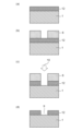
図28には、断面が長方形の凹部9の製造方法を示している。まず図28(a)に示すように、第1の基板1の表面にフォトレジスト6を形成し、露光、現像などを行う事で所望のレジストパターン形状を得る。次に、図28(b)に示すように、フォトレジスト6の上部からエッチング成分10を作用させて第1の基板1の加工を行う。エッチング成分10は一般的なドライエッチングガスや、ウエットエッチング液など等である。最後に、図28(c)で示すようにフォトレジスト6を除去する事で所望の長方形の凹部9が得られる。
FIG. 28 shows a method of manufacturing the
図29には、断面が台形の凹部9の製造方法を示している。まず図29(a)に示すように、第1の基板1の表面にフォトレジスト6を形成し、露光、現像などを行う事で所望のレジストパターン形状を得る。この時、レジストパターン自体にテーパーを付ける為、グラデーションマスクなどを用いて傾斜の付いたレジストパターンを形成する。次に、図29(b)に示すように、フォトレジスト6の上部からエッチング成分10を作用させて第1の基板1の加工を行う。傾斜の付いたレジストパターンを介してエッチングする事で、凹構造の形状もテーパー形状となる。エッチング成分10は一般的なドライエッチングガスや、ウエットエッチング液など等である。最後に、図29(c)で示すようにフォトレジスト6を除去する事で所望の台形の凹部9が得られる。
FIG. 29 shows a method of manufacturing a
図30には、断面が長方形の凹部9の別の製造方法を示している。まず図30(a)に示すように、第1の基板1の表面に加工部材12を形成する。加工部材12とは、後に凹構造となる部分であり、金属膜や樹脂などが選択できる。次に、図30(b)に示すように、第1の基板1の表面にフォトレジスト6を形成し、露光、現像などを行う事で所望のレジストパターン形状を得る。次に、図30(c)に示すように、フォトレジスト6の上部からエッチング成分10を作用させて第1の基板1の加工を行う。エッチング成分10は一般的なドライエッチングガスや、ウエットエッチング液など等であり、加工部材12の材料に応じて変更する。最後に、図30(d)で示すようにフォトレジスト6を除去する事で所望の長方形の凹部9が得られる。
FIG. 30 shows another method of manufacturing the
(実施例)
第1の実施形態を製造する例を記載する。まず初めに、シリコン基板に流路4の加工を施した第1の基板1と第2の基板17を用意する。次に、第1の基板1の接合面に対し、所望の位置へのレジストパターニングやエッチング等を行い、高さ3μmの第1の凸部7を得た。次に、素子基板の接合面に対し、所望の位置へのレジストパターニングやエッチング等を行い、高さ3μmの第2の凸部8を得た。第1の基板1の接合面に接着剤3を5.5μmの高さになるように直描した。その後、第1の基板1と第2の基板17を、接合装置を用いて接合した。この時、接着層11の高さは5μmとなった。その後、流路部材全体を200℃1時間の熱処理を行う事で、連通ボイド5の無い接着層で接合された所望の流路部材を得る事が出来た。
(Example)
An example of manufacturing the first embodiment will be described. First, a
なお、本実施例として示した形状は一例であり、実施形態で示した形状の組み合わせなどで得られる構成についても、本発明の一部に含むものである。また、基板と基板を接着剤で接合する例を示しているが、チップとチップユニットを封止材で接着する際など、類似の用途にも応用し適用できるものである。 Note that the shapes shown in this example are merely examples, and configurations obtained by combinations of the shapes shown in the embodiments are also included as part of the present invention. Further, although an example is shown in which substrates are bonded using an adhesive, the present invention can also be applied to similar applications such as bonding chips and chip units with a sealing material.
1 第1の基板
3 接着剤
7 第1の凸部
8 第2の凸部
17 第2の基板
23 第1の面
24 第2の面
1
Claims (16)
前記第1の面と対向する第2の面を有する第2の基板と、
を備え、
前記第1の面と前記第2の面との間にある接着剤を介して前記第1の基板と前記第2の基板とが接合されている液体吐出ヘッドにおいて、
前記第1の面には、前記第2の面に向かって突出する第1の凸部が形成されており、
前記第2の面には、前記第1の面に向かって突出する第2の凸部が形成されていることを特徴とする液体吐出ヘッド。 a first substrate having a first surface;
a second substrate having a second surface opposite to the first surface;
Equipped with
In a liquid ejection head in which the first substrate and the second substrate are joined via an adhesive between the first surface and the second surface,
A first convex portion protruding toward the second surface is formed on the first surface,
A liquid ejection head characterized in that the second surface is provided with a second convex portion that protrudes toward the first surface.
前記第1の凸部および前記第2の凸部は、前記開口を囲んでいる請求項1ないし7のいずれか1項に記載の液体吐出ヘッド。 A channel opening is formed in the first substrate and the second substrate,
8. The liquid ejection head according to claim 1, wherein the first protrusion and the second protrusion surround the opening.
前記第1の面と対向する第2の面を有する第2の基板と、
を備え、
前記第1の面と前記第2の面との間にある接着剤を介して前記第1の基板と前記第2の基板とが接合されている液体吐出ヘッドにおいて、
前記第1の面には、前記第2の面に向かって突出する凸部が形成されており、
前記第2の面の前記第1の凸部に対向する位置には、凹部が形成されており、
前記凸部の一部は前記凹部に挿入されていることを特徴とする液体吐出ヘッド。 a first substrate having a first surface;
a second substrate having a second surface opposite to the first surface;
Equipped with
In a liquid ejection head in which the first substrate and the second substrate are joined via an adhesive between the first surface and the second surface,
A convex portion protruding toward the second surface is formed on the first surface,
A recess is formed on the second surface at a position opposite to the first convex part,
A liquid ejection head characterized in that a portion of the convex portion is inserted into the concave portion.
Priority Applications (1)
| Application Number | Priority Date | Filing Date | Title |
|---|---|---|---|
| JP2022030748A JP2023127146A (en) | 2022-03-01 | 2022-03-01 | liquid discharge head |
Applications Claiming Priority (1)
| Application Number | Priority Date | Filing Date | Title |
|---|---|---|---|
| JP2022030748A JP2023127146A (en) | 2022-03-01 | 2022-03-01 | liquid discharge head |
Publications (1)
| Publication Number | Publication Date |
|---|---|
| JP2023127146A true JP2023127146A (en) | 2023-09-13 |
Family
ID=87971520
Family Applications (1)
| Application Number | Title | Priority Date | Filing Date |
|---|---|---|---|
| JP2022030748A Pending JP2023127146A (en) | 2022-03-01 | 2022-03-01 | liquid discharge head |
Country Status (1)
| Country | Link |
|---|---|
| JP (1) | JP2023127146A (en) |
-
2022
- 2022-03-01 JP JP2022030748A patent/JP2023127146A/en active Pending
Similar Documents
| Publication | Publication Date | Title |
|---|---|---|
| KR101407582B1 (en) | Nozzle plate of inkjet printhead and method of manufacturing the same | |
| US6361155B1 (en) | Ink jet recording head and method for manufacturing the same | |
| JP7013124B2 (en) | Manufacturing method of liquid discharge head | |
| US7332209B2 (en) | Laminated structure formed of thin plates | |
| US7980675B2 (en) | Ink jet head | |
| JP4277810B2 (en) | Nozzle plate manufacturing method and nozzle plate | |
| US8061809B2 (en) | Liquid ejection head | |
| JP6264902B2 (en) | Liquid ejecting head and liquid ejecting apparatus | |
| JP2023127146A (en) | liquid discharge head | |
| JP2018043426A (en) | Inkjet head and inkjet head manufacturing method | |
| JP2006056103A (en) | Method of manufacturing laminated nozzle plate | |
| JP2002067343A (en) | Long recording head | |
| JP6127491B2 (en) | Liquid ejecting head, liquid ejecting apparatus | |
| JP3244946B2 (en) | Inkjet head | |
| JP2006312239A (en) | Liquid delivering head | |
| JP7047587B2 (en) | Inkjet head and inkjet image forming equipment | |
| JP2013240990A (en) | Liquid ejection head and method of manufacturing the same | |
| JP2006231601A (en) | Laminated nozzle plate, droplet discharge head, and laminated nozzle plate manufacturing method | |
| US7845766B2 (en) | Inkjet recording head | |
| JP6631781B2 (en) | Manufacturing method of flow path member | |
| JP2000211145A (en) | Ink jet recording head and manufacture thereof | |
| JP2009101645A (en) | Recording head and method for manufacturing it | |
| JP5492824B2 (en) | Ink jet head and method of manufacturing ink jet head | |
| JP2007196431A (en) | Liquid droplet delivering head, and method for manufacturing liquid droplet delivering head | |
| JP2007111902A (en) | Inkjet recording head and its manufacturing method |
Legal Events
| Date | Code | Title | Description |
|---|---|---|---|
| RD01 | Notification of change of attorney |
Free format text: JAPANESE INTERMEDIATE CODE: A7421 Effective date: 20231213 |