JP2023103831A - mower - Google Patents

mower Download PDF

Info

Publication number
JP2023103831A
JP2023103831A JP2022004588A JP2022004588A JP2023103831A JP 2023103831 A JP2023103831 A JP 2023103831A JP 2022004588 A JP2022004588 A JP 2022004588A JP 2022004588 A JP2022004588 A JP 2022004588A JP 2023103831 A JP2023103831 A JP 2023103831A
Authority
JP
Japan
Prior art keywords
arm
link
traveling
mower
machine body
Prior art date
Legal status (The legal status is an assumption and is not a legal conclusion. Google has not performed a legal analysis and makes no representation as to the accuracy of the status listed.)
Pending
Application number
JP2022004588A
Other languages
Japanese (ja)
Inventor
幸治 池田
Koji Ikeda
宏明 頭司
Hiroaki Zushi
隆史 藤元
Takashi Fujimoto
文雄 河原
Fumio Kawahara
Current Assignee (The listed assignees may be inaccurate. Google has not performed a legal analysis and makes no representation or warranty as to the accuracy of the list.)
Kobashi Industries Co Ltd
Original Assignee
Kobashi Industries Co Ltd
Priority date (The priority date is an assumption and is not a legal conclusion. Google has not performed a legal analysis and makes no representation as to the accuracy of the date listed.)
Filing date
Publication date
Application filed by Kobashi Industries Co Ltd filed Critical Kobashi Industries Co Ltd
Priority to JP2022004588A priority Critical patent/JP2023103831A/en
Publication of JP2023103831A publication Critical patent/JP2023103831A/en
Pending legal-status Critical Current

Links

Images

Abstract

To provide a mower that can stably travel on a sloped or stepped ridge.SOLUTION: A mower mows grass while traveling on a ridge, and comprises: a machine body; a traveling part; and a link mechanism comprising a first link arm including a first arm part of which one end is rotatably connected to the machine body via a first rotation shaft, and of which the other end is rotatably connected to the traveling part, and a second link arm including a third arm part of which one end is rotatably connected to the machine body via a second rotation shaft, of which the other end is rotatably connected to the traveling part, and arranged in front of the first arm part, and for moving the traveling part with respect to the machine body. When the first arm part is rotated around the first rotation shaft, the first rotation shaft is located between an upper rotation position and a lower rotation position of the other end of the first arm part in a height direction.SELECTED DRAWING: Figure 2

Description

本発明は、草刈り機に関する。 The present invention relates to mowers.

従来、畦の天面又は法面に生えた雑草等を除去するため、草刈り機を用いて、定期的に畦の草刈り作業を行う。特許文献1には、無線通信による遠隔操作によって畦の上を走行しながら、天面及び法面の草刈り作業を行う自走式の草刈り機が記載されている。特許文献1及び2に記載された草刈り機は、左右一対のクローラを備えた走行部、及び、機体前方部に水平刈刃及び傾斜刈刃を有する刈刃部を備え、左右一対のクローラを備えた走行部を用いて畦の上を前後に走行しながら、水平刈刃及び傾斜刈刃を有する刈刃部を用いて天面及び法面に生えた雑草等を除去可能である。 Conventionally, in order to remove weeds and the like that have grown on the top surface or slope of the ridge, the ridge is regularly mowed using a mower. Patent Literature 1 describes a self-propelled mower that cuts grass on top and slope surfaces while traveling on a ridge by remote control using wireless communication. The mowers described in Patent Documents 1 and 2 are equipped with a traveling portion having a pair of left and right crawlers, and a cutting blade portion having a horizontal cutting blade and an inclined cutting blade at the front of the machine body, and a pair of left and right crawlers. It is possible to remove weeds and the like growing on the top surface and the slope surface by using the cutting blade portion having the horizontal cutting blade and the inclined cutting blade while traveling back and forth on the ridge using the traveling portion.

特開2018-157762号公報JP 2018-157762 A 特開2017-176153号公報JP 2017-176153 A

特許文献1及び2に記載された草刈り機の構成は、左右一対のクローラを備えた走行部により前後に移動するだけの構成であるため、例えば畦の天面に傾斜又は段差がある場合には、草刈り機がバランスを崩しやすいという問題がある。 The configuration of the mowers described in Patent Documents 1 and 2 is such that they only move back and forth by the traveling portion provided with a pair of left and right crawlers. There is a problem that the mower tends to lose its balance.

本発明の一実施形態の課題の一つは、傾斜や段差がある畦の上であっても安定して走行可能な草刈り機を提供することにある。 One of the objects of one embodiment of the present invention is to provide a mower that can stably run even on a ridge with slopes and steps.

本発明の一実施形態に係る草刈り機は、畦上を走行しながら草を刈る草刈り機であって機体と、走行部と、第1回動軸において一端を前記機体に回動自在に連結され、他端を前記走行部に対して回動自在に連結された第1アーム部を含む第1リンクアームと、第2回動軸において一端を前記機体に回動自在に連結され、他端を前記走行部に対して回動自在に連結されると共に、前記第1アーム部よりも前方に配置された第3アーム部を含む第2リンクアームと、を有し、前記機体に対して前記走行部を移動させるリンク機構と、を備え、前記第1アーム部を、前記第1回動軸を回動中心として回動させたとき、高さ方向において、前記第1アーム部の前記他端の上回動位置と下回動位置との間に前記第1回動軸が位置する。 A mower according to an embodiment of the present invention is a mower that cuts grass while traveling on a ridge, comprising: a body; a traveling section; a first link arm including a first arm portion rotatably connected to the traveling portion; and a second link arm including a third arm portion that is rotatably connected to and arranged forward of the first arm portion, and moves the traveling portion with respect to the fuselage and a link mechanism that rotates the other end of the first arm portion upward in the height direction when the first arm portion is rotated around the first rotation shaft. The first rotation shaft is positioned between the position and the lower rotation position.

前記第1リンクアームは、第1の方向に延在する前記第1アーム部の前記第1回動軸に連結される前記一端から前記第1の方向とは別方向に延びる第2アーム部を有し、前記第2リンクアームは、第2の方向に延在する前記第3アーム部の前記第2回動軸に連結される前記一端から前記第2の方向とは別方向に延びる第4アーム部を有してもよい。 The first link arm has a second arm portion extending in a direction different from the first direction from the one end connected to the first pivot shaft of the first arm portion extending in the first direction. The second link arm has a fourth link arm extending in a direction different from the second direction from the one end connected to the second pivot shaft of the third arm portion extending in the second direction. You may have an arm part.

前記第1リンクアーム及び前記第2リンクアームを連結するリンクプレートを有してもよい。 A link plate may be provided to connect the first link arm and the second link arm.

一端側を前記機体に連結され、他端側を前記第1リンクアーム又は前記第2リンクアームの一方に連結され、前記リンク機構により前記機体に対して前記走行部を移動させる動力源となるアクチュエータをさらに有してもよい。 An actuator having one end connected to the fuselage and the other end connected to either the first link arm or the second link arm, and serving as a power source for moving the traveling portion relative to the fuselage by the link mechanism. may further have

一端側を前記機体に連結され、他端側を前記アクチュエータが連結されていない前記第1リンクアーム又は前記第2リンクアームに連結され、
前記アクチュエータによる前記機体に対する前記走行部の移動を補助する補助手段をさらに有してもよい。
One end side is connected to the fuselage and the other end side is connected to the first link arm or the second link arm to which the actuator is not connected,
Auxiliary means for assisting movement of the traveling portion relative to the airframe by the actuator may be further provided.

前記アクチュエータは、前記第1リンクアームに連結され、前記補助手段は、前記第2リンクアームに連結されてもよい。 The actuator may be connected to the first link arm and the auxiliary means may be connected to the second link arm.

本発明の一実施形態の草刈り機によれば、傾斜や段差がある畦の上であっても安定して走行可能な草刈り機を提供することができる。 ADVANTAGE OF THE INVENTION According to the mower of one Embodiment of this invention, the mower which can run stably even on the ridge with a slope and a level|step difference can be provided.

本発明の一実施形態に係る草刈り機の構成を示す平面図である。It is a top view showing composition of a mower concerning one embodiment of the present invention. 本発明の一実施形態に係る草刈り機の構成を示す左側面図である。1 is a left side view showing the configuration of a mower according to one embodiment of the present invention; FIG. 図2に示される草刈り機のリンク機構を拡大した図である。Fig. 3 is an enlarged view of the link mechanism of the mower shown in Fig. 2; 本発明の一実施形態に係る草刈り機の構成を示す左側面図である。1 is a left side view showing the configuration of a mower according to one embodiment of the present invention; FIG. 本発明の一実施形態に係る草刈り機の構成を示す背面図である。1 is a rear view showing the configuration of a mower according to one embodiment of the present invention; FIG. 図4に示される草刈り機のリンク機構を拡大した図である。Fig. 5 is an enlarged view of the link mechanism of the mower shown in Fig. 4; 本発明の一実施形態に係る走行部に対する機体の相対的な上下の昇降移動に伴う、左の走行部の前後の移動(位置)を説明するための左側面図である。FIG. 10 is a left side view for explaining the longitudinal movement (position) of the left traveling portion accompanying the vertical movement of the body relative to the traveling portion according to the embodiment of the present invention;

以下、図面を参照して本発明の草刈り機について説明する。但し、本発明の草刈り機は多くの異なる態様で実施することが可能であり、以下に示す例の記載内容に限定して解釈されない。なお、本実施の形態で参照する図面において、同一部分又は同様な機能を有する部分には同一の符号又は同一の符号の後にアルファベットを付し、その繰り返しの説明は省略する場合がある。また、進行方向に対する左右の位置に同一又は類似の部材が設けられている場合、当該部材の符号の後にL(左側の部材)又はR(右側の部材)を付する。左右の部材を特に区別しない場合は、L及びRを省略して説明する場合がある。 The mower of the present invention will be described below with reference to the drawings. However, the mower of the present invention can be embodied in many different forms and should not be construed as limited to the description of the examples given below. In the drawings referred to in the present embodiment, the same parts or parts having similar functions are given the same reference numerals or letters after the same reference numerals, and repetitive description thereof may be omitted. Also, when the same or similar members are provided on the left and right sides with respect to the traveling direction, L (left member) or R (right member) is attached after the reference numeral of the member. When the left and right members are not particularly distinguished, the L and R may be omitted in the description.

本発明の一実施形態において、「上」は、草刈り機が畦に対して草刈り作業を行いながら進行する状態において、畦から垂直に遠ざかる方向を示し、「下」は、「上」とは反対の方向を示す。また、説明の便宜上、「前」は、走行部に対して天面刈取り部が位置する方向を示し、「後」は、「前」とは反対の方向を示す。また、「左」又は「右」は、草刈り機の「後」から草刈り機を見た背面視に対する「左」又は「右」を示す。 In one embodiment of the present invention, "up" indicates a direction in which the mower moves away from the ridge vertically while mowing the ridge, and "down" indicates the direction opposite to "up". indicate direction. For convenience of explanation, "front" indicates the direction in which the top surface reaping portion is positioned with respect to the running portion, and "rear" indicates the direction opposite to "front". Also, "left" or "right" indicates "left" or "right" with respect to a rear view of the mower viewed from the "rear" of the mower.

また、平面視における草刈り機の中心線(進行方向に平行で、かつ、草刈り機の中心を通る線)を基準としたとき、相対的に、中心線に近い側を「内側」と呼び、中心線から遠い側を「外側」と呼ぶ。 In addition, when the center line of the mower in plan view (a line parallel to the direction of travel and passing through the center of the mower) is used as a reference, the side relatively close to the center line is called the "inside", and the The far side is called "outside".

<第1実施形態>
[草刈り機100の構成]
草刈り機100は、走行しながら畦の草刈り作業を行う自走式の草刈り機である。具体的には、リモートコントローラにより遠隔制御され、畦の上を自走して草刈り作業を行う草刈り機である。
<First embodiment>
[Configuration of mower 100]
The mowing machine 100 is a self-propelled mowing machine that cuts grass on a ridge while traveling. Specifically, it is a mowing machine that is remotely controlled by a remote controller and self-propelled on a ridge to mow grass.

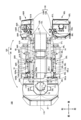
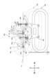
図1、2、及び図5に示される草刈り機100は、畦の天面の左側の段差が畦の天面の右側の段差より低い場合において、左側の走行部20Lが右側の走行部20Rより下方に位置している状態を示している。また、図1、2、及び図5に示される草刈り機100は、左側法面刈取り部80Lの刈面204Lが水平面203に平行又は略平行な状態であり、右側法面刈取り部80Rの204Rと水平面203との間の角度が角度αの状態を示している。図1は、草刈り機100の構成を示す平面図であり、図2は左側の走行部20Lが(右側の走行部20Rより)下がった状態の草刈り機100の構成を示す左側面図であり、図3は図2に示されるリンク機構50L周辺の拡大図であり、図4は左側の走行部20Lが(右側の走行部20Rより)上がった状態の草刈り機100の構成を示す左側面図であり、図5は草刈り機100の構成を示す背面図である。なお、本発明の構成を理解しやすくするため、図2においては、図3に示される符号の一部が省略されている。 In the mower 100 shown in FIGS. 1, 2, and 5, when the step on the left side of the top surface of the ridge is lower than the step on the right side of the top surface of the ridge, the left running portion 20L is lower than the right running portion 20R. It shows the state of being located in 1, 2, and 5, the cutting surface 204L of the left slope cutting portion 80L is parallel or substantially parallel to the horizontal surface 203, and the cutting surface 204R of the right slope cutting portion 80R is parallel to the horizontal surface. 203 indicates the angle α. 1 is a plan view showing the configuration of the mower 100, FIG. 2 is a left side view showing the configuration of the mower 100 with the left running portion 20L lowered (from the right running portion 20R), and FIG. 2 is an enlarged view of the periphery of the link mechanism 50L shown in FIG. 2, and FIG. 4 is a left side view showing the configuration of the mower 100 with the left running portion 20L raised (from the right running portion 20R). 5 is a rear view showing the configuration of the mower 100. FIG. In order to facilitate understanding of the configuration of the present invention, some of the reference numerals shown in FIG. 3 are omitted in FIG.

本実施形態では、刈面204L及び204Rは、左側法面刈取り部80L及び右側法面刈取り部80Rの刃部82L(に含まれる草刈り刃)及び82R(に含まれる草刈り刃)が草を刈る軌跡を含む面(図4)であり、草刈り刃は刈刃と呼ばれる場合がある。 In the present embodiment, the cutting surfaces 204L and 204R are trajectories along which the blade portions 82L (the mowing blades included in) and 82R (the mowing blades included in) of the left slope mowing portion 80L and the right slope mowing portion 80R cut grass. (Fig. 4), and the mowing blade is sometimes called a mowing blade.

図1に示されるように、草刈り機100は、機体10、制御部16、走行部20L及び20R、リンク機構50L及び50R、エンジン60、オルタネータ70、バッテリ40、及び天面刈取り部30及び法面刈取り部80を有する刈取り部120を含む。各部の駆動は制御部16により制御される。草刈り機100は、走行部20L及び20Rで自走しながら、天面刈取り部30及び法面刈取り部80の駆動を制御することで、1回の走行で畦200の天面201及び法面202の草刈り作業を行うことができるようになっている。 As shown in FIG. 1, the mower 100 includes a machine body 10, a control section 16, traveling sections 20L and 20R, link mechanisms 50L and 50R, an engine 60, an alternator 70, a battery 40, a top mowing section 30 and a slope mowing section. It includes a reaping portion 120 having a portion 80 . Driving of each part is controlled by the control part 16 . The mower 100 controls the driving of the top surface mowing unit 30 and the slope surface mowing unit 80 while self-propelled by the traveling units 20L and 20R. It is now possible to do mowing work.

機体10は、草刈り機100の骨格をなすフレームであり、機体本体14及び機体本体14に固定され前方に延びる支持プレート15、機体本体14の前側において外側に張り出すように固定された、リンク機構50L及び50Rを支持するためのリンク支持プレート(図示省略)を含む。支持プレート15には、天面刈取り部30を取り付けるための天面刈取り部取付部11L及び11Rが設けられている。また、機体本体14の後方には、法面刈取り部80を連結するための法面刈取り部取付部12L及び12Rが設けられている。更に、機体本体14の側方には、リンク機構50Lを連結するための第1固定部材57Lと、第1固定部材57Lよりも前方に配置された第2固定部材58Lと、が設けられている(詳細は後述する)。また、機体本体14の側方には、リンク機構50Lと同様に、リンク機構50Rを連結するための第1固定部材(図示は省略)と、当該第1固定部材よりも前方に配置されたリンク機構50Rを連結するための第2固定部材(図示は省略)とが設けられている。機体10は、金属材料(例えば、鋼材、アルミニウム材)、繊維強化プラスチック(FRP)材料等を用いて構成することができるが、この例に限られるものではない。 The machine body 10 is a frame forming the skeleton of the mower 100, and includes a machine body 14, a support plate 15 fixed to the machine body 14 and extending forward, and a link mechanism 50L fixed to the front side of the machine body 14 so as to protrude outward. and a link support plate (not shown) for supporting 50R. The support plate 15 is provided with top surface reaping portion mounting portions 11L and 11R for mounting the top surface reaping portion 30 thereon. In addition, at the rear of the machine body 14, slope reaping part mounting parts 12L and 12R for connecting the slope reaping part 80 are provided. Furthermore, a first fixing member 57L for connecting the link mechanism 50L and a second fixing member 58L arranged forward of the first fixing member 57L are provided on the side of the airframe main body 14. (details will be described later). Further, on the side of the fuselage body 14, similarly to the link mechanism 50L, a first fixing member (not shown) for connecting the link mechanism 50R and a link arranged ahead of the first fixing member are provided. A second fixing member (not shown) for connecting the mechanism 50R is provided. The airframe 10 can be configured using a metal material (for example, steel material, aluminum material), fiber reinforced plastic (FRP) material, or the like, but is not limited to this example.

走行部20L及び20Rは、左右一対のクローラであり、草刈り機100の走行手段として機能する。背面視において、走行部20Lは、草刈り機100の進行方向に向かって左側の走行手段であり、走行部20Rは、右側の走行手段である。なお、走行部20Rの構造は、走行部20Lと同じであるため、ここでは、主に、走行部20Lに着目して説明する。 The traveling units 20L and 20R are a pair of left and right crawlers and function as traveling means of the mower 100. As shown in FIG. In a rear view, the traveling portion 20L is the traveling means on the left side in the traveling direction of the mower 100, and the traveling portion 20R is the traveling means on the right side. Since the structure of the running portion 20R is the same as that of the running portion 20L, the description will be mainly focused on the running portion 20L.

図2に示されるように、走行部20Lは、クローラベルト21L、駆動輪22L、従動輪23L、クローラフレーム24L、及び駆動部54Lを含む。クローラベルト21Lは、駆動輪22L及び従動輪23Lに架け渡され、駆動輪22Lの回転に従って回転する。クローラベルト21Lは、弾性部材(具体的にはゴム)で構成され、複数のラグ部(突出部)を有している。駆動部54Lは、オルタネータ70及びバッテリ40から供給される電力により駆動されるモータで構成されている。駆動輪22Lは、駆動部54Lから伝達された動力により回転する。駆動輪22Lの回転による動力は、クローラベルト21Lを介して従動輪23Lに伝達される。クローラフレーム24Lは、駆動輪22L及び従動輪23Lをそれぞれ回転可能に支持する。本実施形態の走行部20Lは、作業前の調整時において、クローラベルト21Lの接地長を調整可能であるが、作業時においてはクローラベルト21Lの接地長が変化することはない。なお、クローラフレーム24Lには、走行部20Lとリンク機構50Lとを連結するためのリンク取付部材25Lが固定されている。リンク取付部材25Lは、後述の第1リンクアーム51L、第2リンクアーム52Lを取り付けるための取付部として、第1取付部25La及び第2取付部25Lbを有している。第1取付部25La及び第2取付部25Lbは、走行部20L(クローラベルト21L)の上端面の高さ位置よりも上側に突出するように形成されている。 As shown in FIG. 2, the traveling portion 20L includes a crawler belt 21L, drive wheels 22L, driven wheels 23L, a crawler frame 24L, and a drive portion 54L. The crawler belt 21L is stretched over the drive wheel 22L and the driven wheel 23L, and rotates according to the rotation of the drive wheel 22L. The crawler belt 21L is made of an elastic member (specifically, rubber) and has a plurality of lugs (projections). The drive unit 54L is composed of a motor driven by electric power supplied from the alternator 70 and the battery 40 . 22 L of drive wheels rotate with the power transmitted from 54 L of drive parts. Power generated by the rotation of the driving wheels 22L is transmitted to the driven wheels 23L via the crawler belts 21L. The crawler frame 24L rotatably supports the driving wheels 22L and the driven wheels 23L. The running unit 20L of the present embodiment can adjust the contact length of the crawler belt 21L during adjustment before work, but the contact length of the crawler belt 21L does not change during work. A link attachment member 25L for connecting the traveling portion 20L and the link mechanism 50L is fixed to the crawler frame 24L. The link mounting member 25L has a first mounting portion 25La and a second mounting portion 25Lb as mounting portions for mounting a first link arm 51L and a second link arm 52L, which will be described later. The first mounting portion 25La and the second mounting portion 25Lb are formed to protrude upward from the height position of the upper end surface of the traveling portion 20L (crawler belt 21L).

図2又は図4に示されるように、リンク機構50L及び50Rは、機体10と走行部20L及び20Rとを連結し、機体10と走行部20L及び20Rとの位置関係、すなわち機体10に対する走行部20L及び20Rとの距離(間隔)を相対的に変化させ、走行部20L及び20Rに対し、機体10を上限位置と下限位置との間で相対的に移動させる機能を有している。リンク機構50Lは、草刈り機100の進行方向に向かって左側のリンク機構であり、走行部20Lに連結される。リンク機構50Rは、右側のリンク機構であり、走行部20Rに連結される。リンク機構50Rの構造は、リンク機構50Lと同じであるため、ここではリンク機構50Lに着目して説明する。 As shown in FIG. 2 or FIG. 4, the link mechanisms 50L and 50R connect the machine body 10 and the running parts 20L and 20R, and the positional relationship between the machine body 10 and the running parts 20L and 20R, that is, the running parts relative to the machine body 10. It has a function of relatively changing the distance (interval) with 20L and 20R and moving the machine body 10 between the upper limit position and the lower limit position relative to the traveling parts 20L and 20R. The link mechanism 50L is a link mechanism on the left side of the mower 100 in the traveling direction, and is connected to the traveling portion 20L. The link mechanism 50R is a link mechanism on the right side and is connected to the running portion 20R. Since the structure of the link mechanism 50R is the same as that of the link mechanism 50L, the link mechanism 50L will be described here.

リンク機構50Lは、第1リンクアーム51L、第2リンクアーム52L、プレートリンク56L、電動シリンダ53L、及び移動補助機構55Lを含む。 The link mechanism 50L includes a first link arm 51L, a second link arm 52L, a plate link 56L, an electric cylinder 53L, and a movement assist mechanism 55L.

図2又は図3を用いて、リンク機構50Lの構成を説明する。第1リンクアーム51Lは、(側面視)略「L」字状に形成された部材であり、第1の方向に延在する第1アーム部51Ldと、第1の方向と交わり第1の方向とは別方向に延在する第2アーム部51Leと、第1アーム部51Ldと第2アーム部51Leが交わる第1屈曲部51Lb、とを有している。第1屈曲部51Lbは、第1機体側回動軸62により機体本体14(機体10)に固定された第1固定部材57Lに回動自在に連結されており、第1リンクアーム51Lは、第1屈曲部51Lbを介して、機体本体14(機体10)に回動可能に連結される。第1アーム部51Ldの端部である第1端部51Lc(第1端部)は、第1走行部側回動軸61により、クローラフレーム24Lに固定されたリンク取付部材25Lの第1取付部25Laに回動可能に連結される。第2アーム部51Leの端部である第2端部51Laは、電動シリンダ53Lに回動可能に連結されている。 The configuration of the link mechanism 50L will be described using FIG. 2 or FIG. The first link arm 51L is a member formed in a substantially “L” shape (side view), and intersects with the first arm portion 51Ld extending in the first direction and extends in the first direction. and a first bent portion 51Lb where the first arm portion 51Ld and the second arm portion 51Le intersect. The first bending portion 51Lb is rotatably connected to a first fixing member 57L fixed to the body main body 14 (body 10) by a first body-side rotating shaft 62, and the first link arm 51L Via 1 bending part 51Lb, it is connected with the body main body 14 (body 10) so that rotation is possible. A first end portion 51Lc (first end portion), which is an end portion of the first arm portion 51Ld, is a first attachment portion of a link attachment member 25L fixed to the crawler frame 24L by a first traveling portion side rotating shaft 61. 25La is rotatably connected. A second end portion 51La, which is an end portion of the second arm portion 51Le, is rotatably connected to the electric cylinder 53L.

第2リンクアーム52Lは、第1リンクアーム51Lの前方に配設され、側面視において、第1リンクアーム51Lと略同一形状(同一形状含む)に構成されている。第2リンクアーム52Lも第1リンクアーム51Lと同様、(側面視)略「L」字状に形成された部材であり、第2の方向に延在する第3アーム部52Ldと、第2の方向と交わり第2の方向とは別方向に延在する第4アーム部52Leと、第3アーム部52Ldと第4アーム部52Leが交わる第2屈曲部52Lb、とを有している。第3アーム部52Ldは、その端部である第3端部52Lc(第3端部)が、第2走行部側回動軸71により、クローラフレーム24Lに固定されたリンク取付部材25Lの第2取付部25Lbに回動可能に連結される。第2屈曲部52Lbは、第2機体側回動軸72により、機体本体14(機体10)に固定された第2固定部材58Lに対して回動可能に連結されており、第2リンクアーム52Lは、第2屈曲部52Lbを介して機体本体14に回動可能に連結されている。なお、本実施形態では、第1の方向と第2の方向とは同一(略同一も含む)の方向であり、第1の方向と交わり第1の方向とは別方向と、第2の方向と交わり第2の方向とは別方向とは同一(略同一も含む)の方向である。 The second link arm 52L is arranged in front of the first link arm 51L and has substantially the same shape (including the same shape) as the first link arm 51L when viewed from the side. Like the first link arm 51L, the second link arm 52L is also a member formed in a substantially "L" shape (side view). It has a fourth arm portion 52Le intersecting with the second direction and extending in a direction different from the second direction, and a second bending portion 52Lb where the third arm portion 52Ld and the fourth arm portion 52Le intersect. A third end portion 52Lc (third end portion) of the third arm portion 52Ld is attached to the second portion of the link mounting member 25L fixed to the crawler frame 24L by the second traveling portion side rotating shaft 71. It is rotatably connected to the mounting portion 25Lb. The second bending portion 52Lb is rotatably connected to a second fixing member 58L fixed to the body main body 14 (body 10) by a second body-side rotating shaft 72, and the second link arm 52L is rotatably connected to the fuselage body 14 via the second bent portion 52Lb. Note that in the present embodiment, the first direction and the second direction are the same (including substantially the same) direction, and a direction that intersects the first direction and is different from the first direction, and a second direction A direction that intersects with the second direction is a direction that is the same (including substantially the same) as the second direction.

プレートリンク56Lは、第1リンクアーム51Lの第2アーム部51Le及び第2リンクアーム52Lの第4アーム部52Leを連結するプレート状の部材である。なお、便宜上、本実施形態において、第1リンクアーム51Lの第2アーム部51Leの端部を第2端部51La(第2端部)、第2リンクアーム52Lの第4アーム部52Leの端部を第4端部52La(第4端部)と呼ぶこととする。プレートリンク56Lは、後端側を第2端部51La(第2端部)に、前端側を第4端部52La(第4端部)にそれぞれ回動可能に連結されている。なお、プレートリンク56Lと第2アーム部51Leとの連結軸及び電動シリンダ53Lと第2アーム部51Leとの連結軸は、側面視において、同一直線上にある。第1リンクアーム51Lの第2端部51Laと第2リンクアーム52Lの第4端部52Laとの距離を一定に保つと共に、機体10とリンク機構50Lとを水平(平行)に保つことを補助する機能を有する。 The plate link 56L is a plate-shaped member that connects the second arm portion 51Le of the first link arm 51L and the fourth arm portion 52Le of the second link arm 52L. For convenience, in this embodiment, the end of the second arm portion 51Le of the first link arm 51L is referred to as the second end 51La (second end), and the end of the fourth arm portion 52Le of the second link arm 52L is referred to as the second end 51La (second end). is called a fourth end 52La (fourth end). The plate link 56L is rotatably connected to the second end 51La (second end) at the rear end and to the fourth end 52La (fourth end) at the front end. The connecting shaft between the plate link 56L and the second arm portion 51Le and the connecting shaft between the electric cylinder 53L and the second arm portion 51Le are on the same straight line in a side view. While keeping constant the distance between the second end 51La of the first link arm 51L and the fourth end 52La of the second link arm 52L, it assists in keeping the body 10 and the link mechanism 50L horizontal (parallel). have a function.

電動シリンダ53Lは、リンク機構50Lを用いて走行部20Lに対して機体本体14(機体10)を相対的に移動させ、機体本体14と走行部20Lとを離接させるための動力源として機能する。電動シリンダ53Lの前側の一端は、機体本体14(機体10)の上方前方側に配置された支持ブラケット53Laにより回動可能に支持されており、後側の一端は、第1リンクアーム51Lの第2アーム部51Leに回動可能に連結されている。本実施形態では、電動シリンダ53Lが最も伸長したときに、機体本体14と走行部20Lとが最も離間し(図2参照)、走行部20Lを基準としたときに機体10が上限位置に位置する。電動シリンダ53Lが最も収縮したときに、機体本体14と走行部20Lとが最も近接し、走行部20Lを基準としたときに機体10が下限位置に位置する(図4参照)。なお、本実施形態では、アクチュエータの一例として、電動シリンダ53Lを用いているが、アクチュエータは支持ブラケット55Lcと第2アーム部51Leとの間の長さを変更可能な構成であればよい。例えば、アクチュエータは、油圧シリンダであってもよい。 The electric cylinder 53L uses the link mechanism 50L to move the machine body 14 (machine body 10) relative to the traveling part 20L, and functions as a power source for separating and contacting the machine body 14 and the traveling part 20L. . One end on the front side of the electric cylinder 53L is rotatably supported by a support bracket 53La arranged on the upper front side of the machine body 14 (body 10), and one end on the rear side is connected to the first link arm 51L. It is rotatably connected to the second arm portion 51Le. In this embodiment, when the electric cylinder 53L is most extended, the main body 14 and the running portion 20L are separated the most (see FIG. 2), and the fuselage 10 is positioned at the upper limit position when the running portion 20L is used as a reference. . When the electric cylinder 53L is most contracted, the machine body 14 and the running section 20L are closest to each other, and the machine body 10 is positioned at the lower limit position with the running section 20L as a reference (see FIG. 4). In this embodiment, the electric cylinder 53L is used as an example of an actuator, but the actuator may have any configuration as long as the length between the support bracket 55Lc and the second arm portion 51Le can be changed. For example, the actuator may be a hydraulic cylinder.

移動補助機構55Lは、機体本体14に対して走行部20Lを相対的に離間させるとき、すなわち走行部20Lに対して機体本体14の持ち上げ移動するときの動作を補助するための機構である。図1及び図3に示すように、移動補助機構55Lは、第2リンクアーム52Lの第4アーム部52Le(第4端部52Laと第2屈曲部52Lbとの間)に固定された上面視略逆「コ」字状の保持部材55Laと、保持部材55Laに固定され、前方に延びるロッド55Lbと、機体本体14に支持された支持ブラケット55Lcと、支持ブラケット55Lcに回動可能に支持され、ロッド55Lbを挿通する挿通孔が形成された軸状部材55Ldと、保持部材55Laと軸状部材55Ldとの間に介設されてこれらを連結し、ロッド55Lbが挿通されたばね部材55Leと、を有している。ばね部材55Leは、圧縮ばねで構成されている。機体本体14と走行部20Lとを近接させるとき、すなわち走行部20Lに対して機体本体14を下方に移動させるときには、第2リンクアーム52Lの第4アーム部52Leが反時計回りに回動し、ばね部材55Leが収縮する。これに対し、機体本体14と走行部20Lとを離間させるとき、すなわち走行部20Lに対して機体本体14を上方に移動させるときには、第2リンクアーム52Lの第4アーム部52Leは、時計回りに回動する。このとき、ばね部材55Leには、伸長しようとする力が生じており、この力が第4アーム部52Leの時計回りの回動を補助する力として作用する。なお、ばね部材55Leは、圧縮ばねに限定されるものではない。第4アーム部52Leの時計回りの回動を補助する力として作用するものであればよく、ガススプリングやゴムのような弾性部材を用いることも可能である。本実施形態では、移動補助機構55Lは補助手段と呼ばれる場合がある。 The movement assisting mechanism 55L is a mechanism for assisting the operation when the running section 20L is moved relatively away from the machine body 14, that is, when the machine body 14 is lifted and moved with respect to the running section 20L. As shown in FIGS. 1 and 3, the movement assist mechanism 55L is fixed to the fourth arm portion 52Le (between the fourth end portion 52La and the second bent portion 52Lb) of the second link arm 52L. an inverted U-shaped holding member 55La; a rod 55Lb fixed to the holding member 55La and extending forward; A shaft member 55Ld formed with an insertion hole through which the rod 55Lb is inserted, and a spring member 55Le interposed between the holding member 55La and the shaft member 55Ld to connect them and through which the rod 55Lb is inserted. ing. The spring member 55Le is composed of a compression spring. When the machine body 14 and the running section 20L are brought close to each other, that is, when the machine body 14 is moved downward with respect to the running section 20L, the fourth arm section 52Le of the second link arm 52L rotates counterclockwise, The spring member 55Le contracts. On the other hand, when the airframe main body 14 and the traveling portion 20L are separated from each other, that is, when the airframe main body 14 is moved upward with respect to the traveling portion 20L, the fourth arm portion 52Le of the second link arm 52L is rotated clockwise. Rotate. At this time, the spring member 55Le has a force that tends to expand, and this force acts as a force that assists the clockwise rotation of the fourth arm portion 52Le. Note that the spring member 55Le is not limited to a compression spring. An elastic member such as a gas spring or rubber may be used as long as it acts as a force that assists the clockwise rotation of the fourth arm portion 52Le. In this embodiment, the movement assisting mechanism 55L may be called assisting means.

本実施形態では、電動シリンダ53Lの後側の一端が第1リンクアーム51Lの第2アーム部51Leに回動可能に連結され、移動補助機構55Lの保持部材55Laが第4アーム部52Le(第4端部52Laと第2屈曲部52Lbとの間)に固定されている例が示されているが、電動シリンダ53Lの前側の一端は第2リンクアーム52Lの第4アーム部52Leに回動可能に連結され、移動補助機構55Lの保持部材55Laは第2アーム部51Le(第2端部51Laと第1屈曲部51Lbとの間)に固定されていてもよい。すなわち、電動シリンダ53Lは、第1リンクアーム51L及び第2リンクアーム52Lを回動可能なように、機体本体14と、第1リンクアーム51L又は第2リンクアーム52Lの一方に連結され、移動補助機構55L(保持部材55La)は機体本体14と、電動シリンダ53Lが連結されていない第1リンクアーム51L又は第2リンクアーム52Lの他方に連結されていればよい。 In this embodiment, one end on the rear side of the electric cylinder 53L is rotatably connected to the second arm portion 51Le of the first link arm 51L, and the holding member 55La of the movement assisting mechanism 55L is connected to the fourth arm portion 52Le (fourth arm portion 52Le). 52La and the second bent portion 52Lb), one end on the front side of the electric cylinder 53L is rotatable to the fourth arm portion 52Le of the second link arm 52L. The holding member 55La of the movement assisting mechanism 55L may be fixed to the second arm portion 51Le (between the second end portion 51La and the first bent portion 51Lb). That is, the electric cylinder 53L is connected to the machine body 14 and one of the first link arm 51L and the second link arm 52L so that the first link arm 51L and the second link arm 52L can rotate, thereby assisting movement. The mechanism 55L (holding member 55La) may be connected to the machine body 14 and the other of the first link arm 51L and the second link arm 52L to which the electric cylinder 53L is not connected.

本実施形態においては、第1リンクアーム51Lの第1アーム部51Ld、第2リンクアーム52Lの第3アーム部52Ld、リンク取付部材25L及び機体本体14(機体10)によって平行リンクが構成される。また、第1リンクアーム51Lの第2アーム部51Le、第2リンクアーム52Lの第4アーム部52Le、プレートリンク56L及び機体本体14(機体10)によっても平行リンクが構成されている。電動シリンダ53Lを伸長させると、平行リンクが時計回り(右回り)に回動して、機体本体14(機体10)に対して走行部20Lが離間していく。一方、電動シリンダ53Lを収縮すると、平行リンクが反時計回り(左回り)に回動して、機体本体14(機体10)に対して走行部20Lが近接していく。 In this embodiment, a parallel link is configured by the first arm portion 51Ld of the first link arm 51L, the third arm portion 52Ld of the second link arm 52L, the link mounting member 25L, and the fuselage body 14 (body 10). A parallel link is also configured by the second arm portion 51Le of the first link arm 51L, the fourth arm portion 52Le of the second link arm 52L, the plate link 56L, and the body body 14 (body 10). When the electric cylinder 53L is extended, the parallel link rotates clockwise (clockwise), and the traveling portion 20L is separated from the machine body 14 (machine body 10). On the other hand, when the electric cylinder 53L is contracted, the parallel link rotates counterclockwise (counterclockwise), and the traveling portion 20L approaches the machine body 14 (machine body 10).

機体本体14(機体10)に対して、相対的に走行部20L、20Rを離接させる動作についての詳細は後述するが、草刈り機100では、電動シリンダ53L及び53Rを伸縮させて平行リンクをそれぞれ独立に制御し、駆動させることにより、天面又は地面の段差に応じて、リンク機構50L及び50R(走行部20L及び20R)をそれぞれ独立に駆動させることができる。これにより、草刈り機100は、畦の凹凸や段差により、走行部20Lが下がったときには、機体本体14を走行部20Lから離間するようにリンク機構50Lを動作させ、走行部20Lに対して機体本体14を上方に移動させると共に、走行部20Lが上がったときには、機体本体14を走行部20Lに近接するようにリンク機構50Lを動作させ、走行部20Lに対して機体本体14を下方に移動させることで、機体本体14の水平姿勢を保ちながら走行することができる。 Details of the movement of moving the traveling parts 20L and 20R relative to the machine body 14 (machine body 10) will be described later. , the link mechanisms 50L and 50R (running parts 20L and 20R) can be driven independently according to the step on the top surface or on the ground. As a result, the mower 100 operates the link mechanism 50L so as to separate the machine body 14 from the traveling section 20L when the traveling section 20L is lowered due to the unevenness of the ridge or the difference in level. is moved upward, and when the running portion 20L is raised, the link mechanism 50L is operated so that the body body 14 approaches the running portion 20L, and the body body 14 is moved downward with respect to the running portion 20L. , the vehicle body 14 can travel while maintaining its horizontal posture.

なお、リンク機構50Lは、機体本体14に固定された図示省略のリンク支持プレート(機体10)上に支持されている。リンク機構50Lは、草刈り機100の幅がコンパクトになるように、機体10に搭載された最大幅を有する搭載物(本実施形態ではエンジン60)の幅に対応させ、当該搭載物の側端面に沿うように、当該搭載物に並設される。このとき、図2等に示すように、側面視において、エンジン60がリンク機構50Lの電動シリンダ53Lと重なる位置に配置されるが、本実施形態では、図5に示すように、中心側から外側に向かい、移動補助機構55L、電動シリンダ53Lの順で配置することにより、電動シリンダ53Lがエンジン60からの(熱等の)影響を受けにくいように配慮されている。 The link mechanism 50L is supported on a link support plate (not shown) fixed to the body 14 (the body 10). The link mechanism 50L corresponds to the width of the maximum width of the load (in this embodiment, the engine 60) mounted on the machine body 10 so that the width of the mower 100 is compact, and extends along the side end surface of the load. , are arranged side by side with the mounted object. At this time, as shown in FIG. 2 and the like, the engine 60 is arranged at a position overlapping the electric cylinder 53L of the link mechanism 50L in a side view. , the movement assist mechanism 55L and the electric cylinder 53L are arranged in this order, so that the electric cylinder 53L is less likely to be affected by the engine 60 (such as heat).

なお、本実施形態の草刈り機100では、側面視において、第1リンクアーム51Lの第1アーム部51Ldが第2アーム部51Leの長さよりも長く構成されているが、これに限定されない。第1アーム部51Ld及び第2アーム部51Leの長さは、走行部20Lの持ち上げに必要となる力と、電動シリンダ53Lのストローク長とを考慮して適宜変更可能であり、第1アーム部51Ldを第2アーム部51Leよりも短く構成することも可能である。また、第1アーム部51Ldと第2アーム部51Leとの交差角度(第1屈曲部51Lbの角度)も適宜変更可能である。第2リンクアーム52Lの第3アーム部52Ld及び第4アーム部52Leの長さや第2屈曲部52Lbの角度についても、第1リンクアーム51Lと同様である。 In the mower 100 of the present embodiment, the first arm portion 51Ld of the first link arm 51L is longer than the second arm portion 51Le in side view, but the present invention is not limited to this. The lengths of the first arm portion 51Ld and the second arm portion 51Le can be appropriately changed in consideration of the force required to lift the traveling portion 20L and the stroke length of the electric cylinder 53L. can be configured to be shorter than the second arm portion 51Le. Also, the intersection angle between the first arm portion 51Ld and the second arm portion 51Le (the angle of the first bent portion 51Lb) can be changed as appropriate. The lengths of the third arm portion 52Ld and the fourth arm portion 52Le of the second link arm 52L and the angle of the second bent portion 52Lb are the same as those of the first link arm 51L.

図1、図2又は図4に戻って説明を続ける。図1、図2又は図4に示されるように、制御部16は、例えば、機体10の上方かつ後方に配置され、走行部20、刈取り部120、及びバッテリ40を制御する機能を有する。制御部16は、例えば、演算装置、メモリ、及び通信回路等を備えた電子回路基板を有している。例えば、メモリには、草刈り機100の各部を各種制御するための制御プログラムが記憶されており、演算装置はメモリから制御プログラムを読み出し、制御プログラムに基づき、走行部20、リンク機構50L及び50R、並びに、天面刈取り部30及び法面刈取り部80を制御する。図示省略したが、草刈り機100の機体本体14には、機体本体14の姿勢を検出するためのIMU(Inertial Measurement Unit:慣性計測ユニット)が搭載されており、制御部16が、IMUにより検出した機体本体14の姿勢に基づいて電動シリンダ53L、53Rの駆動を制御することで、機体本体14(機体10)の姿勢が水平に保持される。 Returning to FIG. 1, FIG. 2, or FIG. 4, description continues. As shown in FIG. 1 , FIG. 2 or FIG. 4 , the control unit 16 is arranged above and behind the machine body 10 and has a function of controlling the traveling unit 20 , the reaping unit 120 and the battery 40 . The control unit 16 has, for example, an electronic circuit board including an arithmetic unit, memory, communication circuit, and the like. For example, the memory stores a control program for variously controlling each part of the mower 100, and the arithmetic device reads the control program from the memory, and based on the control program, the traveling part 20, the link mechanisms 50L and 50R, and the , the top surface reaping unit 30 and the slope reaping unit 80 are controlled. Although not shown, the machine body 14 of the mower 100 is equipped with an IMU (Inertial Measurement Unit) for detecting the attitude of the machine body 14, and the controller 16 detects the machine body detected by the IMU. By controlling the driving of the electric cylinders 53L and 53R based on the attitude of the body 14, the attitude of the body body 14 (body 10) is held horizontally.

エンジン60は、機体10の上方かつ前方に備えられる。エンジン60は、天面刈取り部30に含まれる刃部32L及び32Rを駆動する駆動部33L及び33Rの動力源、及びオルタネータ70の動力源として機能する。なお、エンジン60で生成された動力は、ベルト等で構成された動力伝達手段(図示省略)を介して、駆動部33L及び33R、並びに、別途設けたオルタネータ70に伝達される。動力伝達手段は、例えば、オルタネータ70へ動力を伝達するための第1の動力伝達手段(図示省略)と、天面刈取り部30へ動力を伝達するための第2の動力伝達手段(図示省略)と、を含んでいる。 The engine 60 is provided above and in front of the airframe 10 . The engine 60 functions as a power source for the drive portions 33L and 33R that drive the blade portions 32L and 32R included in the top surface reaping portion 30 and as a power source for the alternator 70 . The power generated by the engine 60 is transmitted to the drive units 33L and 33R and the separately provided alternator 70 via a power transmission means (not shown) such as a belt. The power transmission means includes, for example, a first power transmission means (not shown) for transmitting power to the alternator 70 and a second power transmission means (not shown) for transmitting power to the top surface reaping section 30. and includes

オルタネータ70は、例えば、支持プレート15の上方に配置されている。オルタネータ70及びエンジン60には、第1の動力伝達手段のベルト(図示省略)が架け渡されている。ベルトを介してエンジンの動力が伝達されることにより、オルタネータ70は電力を生成する。オルタネータ70は、生成した電力をバッテリ40に供給すると共に、法面刈取り部80に含まれる刃部82L及び82Rを駆動する駆動部83L及び83R、及び走行部20を駆動する駆動部54L及び54Rの動力源として機能する。また、オルタネータ70によって生成された電力は、ワイヤーハーネス、ハーネスケーブルなどと呼ばれる電力及び/又は制御信号(電気信号)を供給する電力供給手段(図示省略)を介して、駆動部83L及び83R、駆動部54L及び54R、駆動部33L及び33R、並びに、バッテリ40に供給される。 The alternator 70 is arranged above the support plate 15, for example. A belt (not shown) of the first power transmission means is stretched over the alternator 70 and the engine 60 . The alternator 70 generates electric power as the power of the engine is transmitted through the belt. The alternator 70 supplies the generated electric power to the battery 40, and also drives the driving portions 83L and 83R that drive the blade portions 82L and 82R included in the slope reaping portion 80, and the driving portions 54L and 54R that drives the traveling portion 20. Acts as a power source. Further, the electric power generated by the alternator 70 is supplied to the driving units 83L and 83R, the driving units 83L and 83R, and the driving units 83L and 83R through a power supply means (not shown) called a wire harness or harness cable that supplies electric power and/or a control signal (electrical signal). It is supplied to the sections 54L and 54R, the drive sections 33L and 33R, and the battery 40.

なお、オルタネータ70には、発電制御を行うための発電制御回路(図示省略)が搭載されている。草刈り機100には、バッテリ電圧を検知するセンサ(図示省略)が設けられており、センサによって検知された結果を発電制御回路がモニタリングして、その発電状態をオルタネータ70自身が制御するようになっている。発電制御回路は、バッテリ電圧をモニタリングしており、バッテリ電圧が所定値を下回れば、電力を生成して給電状態となり、バッテリ電圧が所定値を上回れば給電停止となるように、オルタネータ70を制御する。 The alternator 70 is equipped with a power generation control circuit (not shown) for controlling power generation. The mower 100 is provided with a sensor (not shown) that detects the battery voltage, and the power generation control circuit monitors the results detected by the sensor, and the alternator 70 itself controls the power generation state. there is The power generation control circuit monitors the battery voltage, and controls the alternator 70 so that when the battery voltage falls below a predetermined value, power is generated and power is supplied, and when the battery voltage exceeds a predetermined value, power supply is stopped. do.

バッテリ40は、例えば、機体10の上方、かつ、エンジン60と制御部16との間に配置されている。バッテリ40は、オルタネータ70で生成された電力を蓄電する。バッテリ40は、蓄電した電力を、法面刈取り部80に含まれる刃部82L及び82Rを駆動する駆動部83L及び83R(図1、図2又は図3を参照)、及び走行部20を前後に駆動する駆動部54L及び54R(図1、図2又は図3を参照)に供給する動力源として機能する。また、バッテリ40は、蓄電した電力を、機体10と走行部20の間の上下の位置関係を変化させるリンク機構50L及び50Rを動作させるための電動シリンダ53L及び53Rに供給する動力源として機能する。バッテリ40に蓄電された電力は、オルタネータ70と同様の電力供給手段を介して、駆動部83L及び83R、駆動部54L及び54R、及び電動シリンダ53L及び53Rに供給される。 The battery 40 is arranged, for example, above the airframe 10 and between the engine 60 and the controller 16 . Battery 40 stores electric power generated by alternator 70 . The battery 40 supplies the stored electric power to the drive units 83L and 83R (see FIG. 1, FIG. 2 or 3) that drive the blade units 82L and 82R included in the slope reaping unit 80, and the traveling unit 20 forward and backward. It functions as a power source that supplies drive parts 54L and 54R (see FIG. 1, FIG. 2 or FIG. 3). In addition, the battery 40 functions as a power source that supplies the stored electric power to the electric cylinders 53L and 53R for operating the link mechanisms 50L and 50R that change the vertical positional relationship between the machine body 10 and the travel section 20. . The electric power stored in the battery 40 is supplied to the drive units 83L and 83R, the drive units 54L and 54R, and the electric cylinders 53L and 53R through power supply means similar to the alternator 70.

なお、草刈り機100は、カバー部材を含んでよい。カバー部材は、制御部16、バッテリ40、オルタネータ70、及びエンジン60を覆い、保護する役割を有する。また、カバー部材は、制御部16、バッテリ40、オルタネータ70、及びエンジン60の一部を覆う構成としてもよい。 In addition, the mower 100 may include a cover member. The cover member has a role of covering and protecting the control section 16 , the battery 40 , the alternator 70 and the engine 60 . Also, the cover member may be configured to partially cover the control unit 16 , the battery 40 , the alternator 70 , and the engine 60 .

続いて、図1、図2、図4、又は図5を用いて、刈取り部120について説明する。刈取り部120は、走行部20の前方に設けられる天面刈取り部30、及び走行部20の後方に設けられる法面刈取り部80を有する。本実施形態では、天面刈取り部30は、機体10が進行する方向(前方)に配置され、畦に生えた雑草等の草を刈る作業(草刈り作業)を行う草刈り手段として機能する。また、法面刈取り部80は、機体10が進行する方向と180度反対(後方)に配置され、畦に生えた雑草等の草を刈る作業(草刈り作業)を行う草刈り手段として機能する。なお、草刈り機100において、法面刈取り部80が走行部20に対して前方に設けられ、天面刈取り部30が走行部20に対して後方に設けられてもよく、このとき、左、及び右は、前方から見た場合の左、及び右に対応する。 Next, the reaping part 120 will be described with reference to FIG. 1, FIG. 2, FIG. 4, or FIG. The reaping unit 120 has a top surface reaping unit 30 provided in front of the traveling unit 20 and a slope reaping unit 80 provided behind the traveling unit 20 . In the present embodiment, the top surface mowing unit 30 is arranged in the direction (forward) in which the machine body 10 advances, and functions as mowing means for mowing grass such as weeds that have grown on a ridge (mowing work). The slope mowing unit 80 is arranged 180 degrees opposite (rearward) to the direction in which the machine body 10 moves, and functions as mowing means for mowing grass such as weeds growing on a ridge (mowing work). In the mower 100, the slope mowing part 80 may be provided in front of the traveling part 20, and the top surface mowing part 30 may be provided behind the traveling part 20. At this time, the left and right correspond to left and right when viewed from the front.

天面刈取り部30は、ケーシング31、左右に並んで配置された2つの刃部32L及び32R、並びに駆動部33L及び33Rを含む。駆動部33L及び33Rは、天面刈取り部取付部11L及び11Rに連結されている。ケーシング31は、刃部32L及び32Rの上方及び側方を覆い、土、小石、草などの周囲への飛散を防ぐ。刃部32L、及び駆動部33Lの構造は、刃部32R、及び駆動部33Rの構造と同じであるため、ここでは刃部32R、及び駆動部33Rに着目して説明する。 The top surface reaping unit 30 includes a casing 31, two blades 32L and 32R arranged side by side, and driving units 33L and 33R. The drive portions 33L and 33R are connected to the top surface reaping portion mounting portions 11L and 11R. The casing 31 covers the upper and lateral sides of the blades 32L and 32R to prevent soil, pebbles, grass and the like from scattering around. Since the structures of the blade portion 32L and the driving portion 33L are the same as the structures of the blade portion 32R and the driving portion 33R, the blade portion 32R and the driving portion 33R will be described here.

図2、図4又は図5に示されるように、刃部32Rは、複数の草刈り刃を有している。刃部32Rは、駆動部33Rの回転軸に接続され、エンジン60からの動力により回転する。駆動部33Lの回転軸の回転により、複数の草刈り刃も回転し、刃部32Rは草を刈るように構成されている。駆動部33Rは、ベルト(図示省略)を含む第2の動力伝達手段(図示省略)を有し、エンジン60からの動力を刃部32Rに伝達する。 As shown in FIG. 2, FIG. 4 or FIG. 5, the blade portion 32R has a plurality of mowing blades. The blade portion 32R is connected to the rotating shaft of the driving portion 33R and is rotated by power from the engine 60. As shown in FIG. A plurality of mowing blades are also rotated by the rotation of the rotary shaft of the driving portion 33L, and the blade portion 32R is configured to mow the grass. The driving portion 33R has a second power transmission means (not shown) including a belt (not shown), and transmits power from the engine 60 to the blade portion 32R.

本実施形態では、刃部32L及び32Rは、機体10の中心線110に対して、左右対称又は左右略対称に備えられ、静止時において相互に干渉しないように位相ずれして配設されている。第2の動力伝達手段は、ベルトを介して伝達されるエンジン60の駆動力を、駆動部33L及び33Rの両方に均等又は略均等に伝達するように設計されている。したがって、刃部32Lの複数の草刈り刃及び刃部32Rの複数の草刈り刃は同じタイミングかつ同じ速度で回転する。 In this embodiment, the blades 32L and 32R are provided symmetrically or substantially symmetrically with respect to the center line 110 of the fuselage 10, and are arranged out of phase so as not to interfere with each other when stationary. . The second power transmission means is designed to evenly or substantially evenly transmit the driving force of the engine 60 transmitted via the belt to both the driving portions 33L and 33R. Therefore, the mowing blades of the blade portion 32L and the mowing blades of the blade portion 32R rotate at the same timing and at the same speed.

草刈り機100では、天面刈取り部30の刃部32を回転させるための動力源として、エンジン60を使用する例が示される。しかし、ここで説明した例に限らず、刃部32L及び32Rを回転させるための動力源として、モータを用いることも可能である。この場合、制御部を用いて、駆動部33L及び33Rを独立に制御し、刃部32L及び32Rを独立に駆動する構成としてもよい。 In the mower 100, an example is shown in which the engine 60 is used as a power source for rotating the blade portion 32 of the top surface mowing portion 30. FIG. However, it is also possible to use a motor as a power source for rotating the blade portions 32L and 32R without being limited to the example described here. In this case, the control section may be used to independently control the drive sections 33L and 33R and independently drive the blade sections 32L and 32R.

法面刈取り部80は、左右一対の左側法面刈取り部80L及び右側法面刈取り部80Rを含んでいる。また、図1に示されるように、草刈り機100は、左右一対の法面刈取り部取付部12L及び12R、並びに、左右一対の角度調整機構130L及び130Rを有する。草刈り機100の機体本体14(機体10)の後方の端部は、中心線110に対して対称又は略対称に位置する後方左の端部17L及び後方右の端部17Rである。 The slope mowing part 80 includes a pair of left and right slope mowing parts 80L and a right slope mowing part 80R. Further, as shown in FIG. 1, the mower 100 has a pair of left and right slope mower mounting portions 12L and 12R and a pair of left and right angle adjustment mechanisms 130L and 130R. The rear ends of the machine body 14 (body 10 ) of the mower 100 are a rear left end 17 L and a rear right end 17 R located symmetrically or substantially symmetrically with respect to the centerline 110 .

左側法面刈取り部80L及び右側法面刈取り部80Rは、それぞれ、ケーシング81L及び81R、刃部82L及び82R、駆動部83L及び83R、法面刈取り部支持部89L及び89R、並びに取っ手140L及び140Rを含む。刃部82L及び刃部82Rは、天面刈取り部30の刃部32L及び32Rと同様に、複数の草刈り刃を有し、複数の草刈り刃を有する刃部82L及び刃部82Rが回転することにより、畦に生えた草を刈る。なお、左側法面刈取り部80Lの構造は、右側法面刈取り部80Rの構造と同様であるため、ここでは右側法面刈取り部80Rに着目して説明する。 The left slope reaping unit 80L and the right slope reaping unit 80R include casings 81L and 81R, blades 82L and 82R, drive units 83L and 83R, slope reaping unit supports 89L and 89R, and handles 140L and 140R, respectively. include. The blade portion 82L and the blade portion 82R have a plurality of mowing blades in the same manner as the blade portions 32L and 32R of the top surface mowing portion 30. When the blade portion 82L and the blade portion 82R having a plurality of mowing blades rotate, , mow the grass that grows on the ridge. Since the structure of the left slope reaping part 80L is the same as the structure of the right side slope reaping part 80R, the right side slope reaping part 80R will be described here.

右側法面刈取り部80Rは、法面刈取り部取付部12R、角度調整機構130R、及び法面刈取り部支持部89Rを介して、後方右の端部17Rに連結されている。 The right slope reaping portion 80R is connected to the rear right end portion 17R via a slope reaping portion mounting portion 12R, an angle adjustment mechanism 130R, and a slope reaping portion support portion 89R.

法面刈取り部支持部89Rがケーシング81Rに取付けられる。ケーシング81Rは、法面刈取り部支持部89Rを介して、角度調整機構130Rに連結される。ケーシング81Rは、刃部82Rを覆い、天面刈取り部30のケーシング31と同様に、土、小石、草などの周囲への飛散を防ぐ。取っ手140Rがケーシング81Rに取付けられている。取っ手140Rは右側法面刈取り部80Rを角度調整する際の把持部となる。駆動部83Rは刃部82Rに連結され、刃部82Rを回転させるための部位であり、オルタネータ70及びバッテリ40から供給される動力により駆動されるモータを有している。本実施形態では、ケーシング81Rはカバー部と呼ばれる場合があり、ケーシング81Rに覆われていない刃部82Rは、畦200に面している。 A slope cutting support 89R is attached to the casing 81R. The casing 81R is connected to the angle adjustment mechanism 130R via the slope reaping portion support portion 89R. The casing 81R covers the blade portion 82R and, like the casing 31 of the top surface reaping portion 30, prevents soil, pebbles, grass, and the like from scattering around. A handle 140R is attached to the casing 81R. The handle 140R serves as a grasping portion for adjusting the angle of the right slope reaping portion 80R. The driving portion 83R is connected to the blade portion 82R, is a portion for rotating the blade portion 82R, and has a motor driven by power supplied from the alternator 70 and the battery 40. As shown in FIG. In this embodiment, the casing 81R may be called a cover portion, and the blade portion 82R that is not covered with the casing 81R faces the ridge 200. As shown in FIG.

草刈り機100では、制御部16を用いて、駆動部83L及び83Rが独立に制御される。駆動部83L及び83Rは、オルタネータ70又はバッテリ40から供給される電力を刃部82L及び82Rに供給する。 In the mower 100, the drive units 83L and 83R are independently controlled using the control unit 16. FIG. The drive units 83L and 83R supply power supplied from the alternator 70 or the battery 40 to the blade units 82L and 82R.

角度調整機構130(130L及び130R)は、畦200の天面201の幅に応じて、予め、左側法面刈取り部80L及び右側法面刈取り部80Rの位置を調整し、左側法面刈取り部80L及び右側法面刈取り部80Rの位置に合わせて、刈面204L又は204Rと水平面203との間の角度αをそれぞれ独立して調整することができる(図5を参照)。なお、角度調整機構130Lの構造は、角度調整機構130Rの構造と同様であるため、ここでは、図5を用いて、角度調整機構130Rに着目して説明する。 The angle adjustment mechanism 130 (130L and 130R) adjusts the positions of the left slope cutting portion 80L and the right slope cutting portion 80R in advance according to the width of the top surface 201 of the ridge 200, and adjusts the left slope cutting portion 80L. and the angle .alpha. Since the structure of the angle adjustment mechanism 130L is the same as that of the angle adjustment mechanism 130R, the angle adjustment mechanism 130R will be described here with reference to FIG.

角度調整機構130Rは、例えば、ロックプレート131R、法面刈取り部取付ピン132R、及び角度調整ピン133Rを含む。また、角度調整機構130Rは、法面刈取り部取付ピン132Rを用いて、法面刈取り部取付部12R及び法面刈取り部支持部89Rの間に接続され、法面刈取り部取付部12R及び法面刈取り部支持部89Rに回動可能に連結される。角度調整ピン133Rは、法面刈取り部支持部89Rに形成された挿通孔に挿通されると共に当該挿通孔に固定される。ロックプレート131Rは、角度調整ピン133Rに係合して刈面204Rの角度を位置決め固定する位置決め凹部131Raを複数(本実施形態では4つ)有している。 The angle adjustment mechanism 130R includes, for example, a lock plate 131R, a slope reaping portion attachment pin 132R, and an angle adjustment pin 133R. In addition, the angle adjustment mechanism 130R is connected between the slope reaping part mounting part 12R and the slope reaping part support part 89R using the slope reaping part mounting pin 132R. It is rotatably connected to the reaping part support part 89R. The angle adjustment pin 133R is inserted through an insertion hole formed in the slope reaping portion support portion 89R and is fixed to the insertion hole. The lock plate 131R has a plurality of (four in this embodiment) positioning recesses 131Ra that engage with the angle adjustment pins 133R to position and fix the angle of the cutting surface 204R.

図5を参照して、角度調整機構130Rを用いた、右側法面刈取り部80Rの角度調整動作について説明する。取っ手140Rを持って、右側法面刈取り部80Rを操作し、位置決め凹部131Raから角度調整ピン133Rが外れるように右側法面刈取り部80Rを移動させる。この時、法面刈取り部支持部89Rは角度調整ピン133Rと共に、法面刈取り部取付部12R及びロックプレート131Rに対して回動する。初めに嵌っていた位置決め凹部131aとは異なる位置決め凹部131Raに角度調整ピン133Rを嵌め込むことで、刈面204Rと水平面203との間の角度αを変えることができる。 The angle adjustment operation of the right slope reaping portion 80R using the angle adjustment mechanism 130R will be described with reference to FIG. Holding the handle 140R, the right slope reaping part 80R is operated to move the right slope reaping part 80R so that the angle adjustment pin 133R is removed from the positioning recess 131Ra. At this time, the slope reaping part support part 89R rotates with the angle adjustment pin 133R with respect to the slope reaping part attachment part 12R and the lock plate 131R. The angle α between the cutting surface 204R and the horizontal surface 203 can be changed by fitting the angle adjustment pin 133R into the positioning recess 131Ra different from the positioning recess 131a that was initially fitted.

本実施形態では、草刈り機100の背面視(図5)において、一番左の位置決め凹部131Raに角度調整ピン133Rを嵌め込むと、角度αは90度、すなわち、刈面204Rが水平面203に対して垂直又は略垂直となり、一番右の位置決め凹部131Raに角度調整ピン133Rを嵌め込むと、角度αは180度、すなわち、刈面204Rが水平面203に平行又は略平行となるように構成されている。なお、角度αが180度の状態は、図1、図2、図4及び図5に示される左側法面刈取り部80Lの状態である。 In this embodiment, when the angle adjustment pin 133R is fitted into the leftmost positioning recess 131Ra in the rear view of the mower 100 (FIG. 5), the angle α is 90 degrees, that is, the cutting surface 204R is positioned with respect to the horizontal surface 203. When the rightmost positioning recess 131Ra is fitted with the angle adjustment pin 133R, the angle α is 180 degrees, that is, the cutting surface 204R is parallel or substantially parallel to the horizontal surface 203. . The state in which the angle α is 180 degrees is the state of the left slope cutting portion 80L shown in FIGS.

図1、図2、図4及び図5に示されるように、草刈り機100は、刈面204L及び204Rと水平面203との間の角度αを左右非対称に(異なる角度に)調整して草刈り作業を行うことが可能である。また、図示は省略されるが、刈面204L及び204Rと水平面203との間の角度αを左右対称に調整された状態で草刈り作業を行うことも可能である。 As shown in FIGS. 1, 2, 4 and 5, the mowing machine 100 performs mowing work by adjusting the angle α between the cutting surfaces 204L and 204R and the horizontal plane 203 asymmetrically (to different angles). It is possible. Although not shown, it is also possible to mow grass in a state in which the angle α between the cutting surfaces 204L and 204R and the horizontal plane 203 is adjusted symmetrically.

[機体10を上下に昇降移動させる動作の例]
図3、図6及び図7を用いて、草刈り機100の機体10(機体本体14)を上下に昇降移動させる動作について説明する。リンク機構50Rの構造は、リンク機構50Lと同じであるため、ここではリンク機構50Lに着目して、走行部20Lに対する機体10(機体本体14)の相対的な上下の昇降移動に伴う、走行部20Lの前後の移動(位置)を説明する。図6は、草刈り機100の左の走行部20Lに対して機体本体14が最も下方に移動したとき(下限位置にあるとき)の状態を説明するための左側面図であり、図7は草刈り機100の左の走行部20Lに対する機体10の上下の昇降移動とこれに伴う機体10の前後の移動(位置)を説明するための左側面図である。
[Example of operation for vertically moving the body 10]
3, 6, and 7, the operation of vertically moving the machine body 10 (machine body 14) of the mower 100 will be described. Since the structure of the link mechanism 50R is the same as that of the link mechanism 50L, attention is focused on the link mechanism 50L here. The forward and backward movement (position) of 20L will be described. FIG. 6 is a left side view for explaining a state when the machine body 14 has moved to the lowest position (lower limit position) with respect to the left running portion 20L of the mower 100, and FIG. 7 is a left side view of the mower 100. Fig. 10 is a left side view for explaining the up-and-down movement of the machine body 10 with respect to the left running portion 20L and the movement (position) of the machine body 10 in the front-rear direction accompanying this.

上述の通り、第1リンクアーム51L、第2リンクアーム52L、リンク取付部材25L及び機体本体14によって平行リンクが構成される。また、電動シリンダ53Lは、一端が機体本体14(支持ブラケット55Lc)に固定されていると共に、他端は第1リンクアーム51Lの第2アーム部51Le(第2端部51La)に連結されている。移動補助機構55Lのばね部材55Leは、一端が機体本体14(支持ブラケット55Lc)に固定されていると共に、他端は第2リンクアーム52Lの第4アーム部52Leに連結されている。プレートリンク56Lは第1リンクアーム51Lの第2アーム部51Le及び第2リンクアーム52Lの第4アーム部52Leを連結している。 As described above, the first link arm 51L, the second link arm 52L, the link mounting member 25L, and the airframe main body 14 constitute a parallel link. The electric cylinder 53L has one end fixed to the machine body 14 (support bracket 55Lc) and the other end connected to the second arm portion 51Le (second end portion 51La) of the first link arm 51L. . The spring member 55Le of the movement assist mechanism 55L has one end fixed to the body body 14 (support bracket 55Lc) and the other end connected to the fourth arm portion 52Le of the second link arm 52L. The plate link 56L connects the second arm portion 51Le of the first link arm 51L and the fourth arm portion 52Le of the second link arm 52L.

図6は、走行部20Lと機体10との相対位置が近接した状態を示した図であり、走行部20Lに対する機体10の上下方向の位置は、図3に示す機体10の上下方向の位置より低い位置である。ここでは、(走行部20Lを基準としたときに)機体10の上下方向の位置が、図6に示す最も下方(下限位置)に位置する状態、及び図3に示す最も上方(上限位置)に位置する状態を例に説明する。なお、図7において、点線で示される走行部20L等は図6に示す走行部20Lと機体10との相対位置が最も近接した状態、すなわち機体10が最も下降した状態を示し、実線で示される走行部L等は図3に示す走行部20Lと機体10との相対位置が最も離間した状態、すなわち機体10が最も上昇した状態を示す。 FIG. 6 is a diagram showing a state in which the relative positions of the traveling portion 20L and the airframe 10 are close to each other. Low position. Here, the position of the body 10 in the vertical direction (when the traveling portion 20L is used as a reference) is positioned at the lowest position (lower limit position) shown in FIG. 6, and at the highest position (upper limit position) shown in FIG. A positional state will be described as an example. In FIG. 7, the running portion 20L and the like indicated by dotted lines indicate the state in which the relative positions of the running portion 20L and the fuselage 10 shown in FIG. A running portion L and the like indicate a state in which the relative positions of the running portion 20L and the body 10 shown in FIG.

図6は、畦の天面の左側に凸出した段差があった場合の草刈り機100の走行状態を説明した図である。畦の天面の左側が凸出した段差を走行すると、走行部20Lと共に機体10も左上がりに傾く。この傾きをIMUにより検知し、その検知結果に応じて、制御部16は、電動シリンダ53Lに、機体10を下方に移動するように制御する信号を送信する。これにより、電動シリンダ53Lが収縮して機体10に対してリンク機構50Lを反時計回りに回動させる。このとき、第1リンクアーム51Lは第1機体側回動軸62を回動中心にして、第2リンクアーム52Lは第2機体側回動軸72を回動中心にして反時計回りに回動する。これにより、畦の段差量に応じて走行部20Lと機体10とが近接し、機体10が下方に移動する。 FIG. 6 is a diagram for explaining the running state of the mower 100 when there is a step that protrudes on the left side of the top surface of the ridge. When traveling on a step where the left side of the top surface of the ridge protrudes, the fuselage 10 also tilts upward to the left together with the traveling portion 20L. This inclination is detected by the IMU, and according to the detection result, the control unit 16 transmits a signal to the electric cylinder 53L to control the body 10 to move downward. As a result, the electric cylinder 53L is contracted to rotate the link mechanism 50L counterclockwise with respect to the airframe 10. As shown in FIG. At this time, the first link arm 51L rotates counterclockwise around the first body-side rotation shaft 62, and the second link arm 52L rotates around the second body-side rotation shaft 72. do. As a result, the traveling portion 20L and the machine body 10 approach each other according to the step amount of the ridge, and the machine body 10 moves downward.

図3は、畦の天面の左側が凹んだ段差があった場合の草刈り機100の走行状態を説明した図である。畦の天面の左側が凹んだ段差を走行すると、走行部20Lと共に機体10も左下がりに傾く。この傾きをIMUにより検知し、その検知結果に応じて、制御部16は、電動シリンダ53Lに、機体10を上方に移動するように制御する信号を送信する。これにより、電動シリンダ53Lが伸長し、機体10に対してリンク機構50Lを時計回りに回動させる。このとき、第1リンクアーム51Lは第1機体側回動軸62を回動中心にして、第2リンクアーム52Lは第2機体側回動軸72を回動中心にして時計回りに回動する。これにより、畦の段差量に応じて走行部20Lと機体10とが離間し、機体10が上方に移動する。 FIG. 3 is a diagram illustrating the running state of the mower 100 when there is a recessed step on the left side of the top surface of the ridge. When the vehicle travels on a level difference in which the left side of the top surface of the ridge is recessed, the vehicle body 10 also tilts downward to the left together with the running portion 20L. This inclination is detected by the IMU, and according to the detection result, the control unit 16 transmits a signal to the electric cylinder 53L to control the body 10 to move upward. As a result, the electric cylinder 53L extends and rotates the link mechanism 50L clockwise with respect to the body 10. As shown in FIG. At this time, the first link arm 51L rotates clockwise around the first body-side rotation shaft 62, and the second link arm 52L rotates clockwise around the second body-side rotation shaft 72. . As a result, the traveling portion 20L and the body 10 are separated from each other according to the step amount of the ridge, and the body 10 moves upward.

なお、本実施形態においては、第2リンクアーム52Lの回動に伴い、移動補助機構55Lのばね部材55Leが伸縮する構成となっている。機体10を走行部20Lに向けて下降させるときには、機体10に対してリンク機構50Lが反時計回りに回動して、第2リンクアーム52Lの第4アーム部52Leがばね部材55Leを収縮させる。機体10を走行部20Lから離間させ、上昇させるときには、収縮状態にあるばね部材55Leの伸長しようとする力が、リンク機構50L(第4アーム部52Le)を時計回りに回動させようとする力として作用する。したがって、走行部20Lに対して機体10を相対的に上昇させるときには、電動シリンダ53Lの推力に加え、移動補助機構55Lのばね部材55Leの力もリンク機構50Lを回動させる力として利用することができため、比較的小型な(推力の小さい)電動シリンダ53Lを使用することができる。 In this embodiment, the spring member 55Le of the movement assisting mechanism 55L expands and contracts as the second link arm 52L rotates. When the body 10 is lowered toward the traveling portion 20L, the link mechanism 50L rotates counterclockwise with respect to the body 10, and the fourth arm portion 52Le of the second link arm 52L contracts the spring member 55Le. When the machine body 10 is moved away from the traveling part 20L and lifted, the force of the spring member 55Le in the contracted state to extend is the force to rotate the link mechanism 50L (fourth arm part 52Le) clockwise. acts as Therefore, when the machine body 10 is raised relative to the traveling part 20L, the force of the spring member 55Le of the movement assisting mechanism 55L can be used as a force to rotate the link mechanism 50L in addition to the thrust of the electric cylinder 53L. Therefore, a relatively small (small thrust) electric cylinder 53L can be used.

走行部20Lに対して機体10を相対的に上昇させるときには、機体10とその搭載物の自重に逆らって、機体10を持ち上げる方向の力が必要となる。本実施形態の草刈り機100では、電動シリンダ53Lの推力に加え、移動補助機構55Lのばね部材55Leの力も機体10を持ち上げる方向の力(リンク機構50Lを回動させる力)として利用することができるため、比較的小型な(推力の小さい)電動シリンダ53Lを使用することができる。また、電動シリンダ53Lは伸長によって駆動すべき負荷に応じて伸長の速度が遅くなる場合があるが、草刈り機100では、ばね部材55Leを用いることによって、電動シリンダ53Lの伸長を補助することができる。その結果、草刈り機100では、安定して機体10の水平状態を保つことができるようになっている。 When the airframe 10 is lifted relative to the traveling section 20L, a force is required to lift the airframe 10 against the weight of the airframe 10 and its load. In the mower 100 of the present embodiment, in addition to the thrust of the electric cylinder 53L, the force of the spring member 55Le of the movement assist mechanism 55L can also be used as the force in the direction of lifting the machine body 10 (the force for rotating the link mechanism 50L). , a relatively small (small thrust) electric cylinder 53L can be used. In addition, the extension speed of the electric cylinder 53L may be slowed down depending on the load to be driven by the extension, but in the mower 100, the extension of the electric cylinder 53L can be assisted by using the spring member 55Le. As a result, the mower 100 can stably maintain the horizontal state of the body 10 .

ところで、走行中の機体10を水平に保つために、リンク機構50Lを回動させると走行部20Lも回動するため、走行部20Lは、機体10に対して相対的に離接する(上下方向に移動する)だけではなく、機体10に対する前後方向の位置も変化する。本実施形態の草刈り機100はリモートコントローラを用いて遠隔操作するものであるが、操作中に、走行部20Lと機体10との(相対的)位置関係が大きく変化すると、ユーザのリモートコントローラの操作感が変わり、ユーザに違和感を与える恐れがある。そこで、本実施形態の草刈り機100では、走行中の機体10の水平制御のためにリンク機構50Lにより走行部20Lを回動させても、機体10に対する走行部20Lの相対的な前後位置が大きく変わらないように構成されている。 By the way, in order to keep the machine body 10 horizontal during traveling, when the link mechanism 50L is rotated, the traveling part 20L is also rotated. move), but also the position in the longitudinal direction with respect to the airframe 10 changes. The mower 100 of the present embodiment is remotely operated using a remote controller. changes, and the user may feel uncomfortable. Therefore, in the mower 100 of the present embodiment, even if the traveling portion 20L is rotated by the link mechanism 50L for horizontal control of the machine body 10 during traveling, the relative longitudinal position of the traveling portion 20L with respect to the machine body 10 changes greatly. configured to prevent

図7を用いて具体的に説明する。図7に示すように、側面視において、本実施形態では、機体10が下限位置にあるときには、機体10に対する第1リンクアーム51L(第1アーム部51Ld)の回動支点である第1機体側回動軸62を通る水平面111の上側に第1アーム部51Ldの第1端部51Lc(第1端部)が位置し、機体10が上限位置にあるときには、水平面111の下側に第1アーム部51Ldの第1端部51Lc(第1端部)が位置する。すなわち、機体10を下限位置から上限位置まで移動させるとき、高さ方向において、第1端部51Lcが最も高くなる位置と第1端部51Lcが最も低くなる位置との間に第1機体側回動軸62が位置する。換言すれば、機体10を下限位置から上限位置まで移動させるときに、第1アーム部51Ldが水平(水平面111と平行)となる状態が存在する。 A specific description will be given with reference to FIG. As shown in FIG. 7, in the side view, in this embodiment, when the body 10 is at the lower limit position, the first body side, which is the pivotal fulcrum of the first link arm 51L (first arm portion 51Ld) with respect to the body 10 The first end 51Lc (first end) of the first arm portion 51Ld is positioned above the horizontal plane 111 passing through the rotation shaft 62, and when the machine body 10 is at the upper limit position, the first arm is positioned below the horizontal plane 111. A first end 51Lc (first end) of the portion 51Ld is located. That is, when the body 10 is moved from the lower limit position to the upper limit position, in the height direction, the first body side rotation is between the highest position of the first end portion 51Lc and the lowest position of the first end portion 51Lc. A drive shaft 62 is located. In other words, there is a state in which the first arm portion 51Ld is horizontal (parallel to the horizontal plane 111) when the body 10 is moved from the lower limit position to the upper limit position.

機体10を下限位置から上限位置まで移動させる場合、第1端部51Lcが水平面111よりも上方にあるときには、走行部20Lは第1アーム部51Ldの回動に伴い後方へ移動する。そして、第1アーム部51Ldが水平になったとき、走行部20Lは(機体に対して)最も後方に位置する状態となる。さらに、第1アーム部51Ldの回動が進み、第1端部51Lcが水平面111よりも下方に位置するようになると、走行部20Lの移動方向が逆転し、走行部20Lは第1アーム部51Ldの回動に伴い前方へ移動する。 When moving the machine body 10 from the lower limit position to the upper limit position, when the first end portion 51Lc is above the horizontal plane 111, the traveling portion 20L moves rearward as the first arm portion 51Ld rotates. Then, when the first arm portion 51Ld becomes horizontal, the running portion 20L is positioned at the rearmost position (relative to the machine body). Further, when the rotation of the first arm portion 51Ld progresses and the first end portion 51Lc is positioned below the horizontal surface 111, the movement direction of the traveling portion 20L is reversed, and the traveling portion 20L moves toward the first arm portion 51Ld. moves forward with the rotation of

このように、水平面111を挟むように第1アーム部51Ldを回動させると、水平面111を挟み、走行部20Lの前後方向における移動方向を逆転することができる。すなわち、第1アーム部51Ld回動時において、水平面111に対する回動通過前と後とで走行部20Lの移動量を相殺することができ、機体10に対する走行部20Lの相対的な前後位置の変化を小さく抑えることができる。 In this way, when the first arm portion 51Ld is rotated so as to sandwich the horizontal surface 111, it is possible to sandwich the horizontal surface 111 and reverse the moving direction of the traveling portion 20L in the front-rear direction. That is, when the first arm portion 51Ld rotates, the amount of movement of the running portion 20L before and after passing through the horizontal plane 111 can be offset, and the change in the relative longitudinal position of the running portion 20L with respect to the machine body 10. can be kept small.

なお、本実施形態では、機体10の上限位置における第1アーム部51Ldと水平面111とのなす角と、機体10の下限位置における第1アーム部51Ldと水平面111とのなす角とが略同じ角度となっているため、図7に示すように、機体10の上限位置及び下限位置における走行部20Lの前後方向の位置は、僅かな距離(距離D2)しか変化せず、全体としての移動量D3も小さくなっている。なお、機体10の上限位置における第1アーム部51Ldと水平面111とのなす角と機体10の下限位置における第1アーム部51Ldと水平面111とのなす角が等しいときに、走行部20Lの全体としての前後方向の移動量D3が最も小さくなるが、これらのなす角をどのように設定するかは適宜調整可能である。第1アーム部51Ldが水平面111より上にあるときの走行部20Lの移動量が、第1アーム部51Ldが水平面111より下にあるときの移動量よりも大きくなるように上記なす角を設定してもよいし、小さくなるように上記なす角を設定してもよい。 In this embodiment, the angle formed by the first arm portion 51Ld and the horizontal plane 111 at the upper limit position of the airframe 10 and the angle formed by the first arm portion 51Ld and the horizontal plane 111 at the lower limit position of the airframe 10 are substantially the same angle. Therefore, as shown in FIG. 7, the longitudinal position of the running portion 20L at the upper limit position and the lower limit position of the machine body 10 changes only by a small distance (distance D2), and the overall movement amount is D3. is also smaller. When the angle formed by the first arm portion 51Ld and the horizontal plane 111 at the upper limit position of the machine body 10 is equal to the angle formed by the first arm portion 51Ld and the horizontal plane 111 at the lower limit position of the machine body 10, the running section 20L as a whole The amount of movement D3 in the front-rear direction of is the smallest, but it is possible to appropriately adjust how to set the angle formed by these. The angle is set so that the amount of movement of the traveling portion 20L when the first arm portion 51Ld is above the horizontal plane 111 is greater than the amount of movement when the first arm portion 51Ld is below the horizontal plane 111. Alternatively, the angle may be set to be small.

ここで、プレートリンク56Lの機能について説明する。上述したように、本実施形態の草刈り機100は、機体10を下限位置から上限位置まで移動させる場合、第1アーム部51Ldが水平面111と平行となる状態が存在する。このとき、第2リンクアーム52Lの第3アーム部52Ldも水平面111と平行な状態となり、第1アーム部51Ld、第3アーム部52Ld、リンク取付部材25L及び機体本体14(機体10)によって構成される平行リンク(第1平行リンク)が不安定な状態となる。そこで、本実施形態の草刈り機100では、第1リンクアーム51Lの第2アーム部51Leの第2端部51La(第2端部)と、第2リンクアーム52Lの第4アーム部52Leの第4端部52La(第4端部)とを、プレートリンク56Lで連結し、リンク機構50Lにおいて、第2アーム部51Le、第4アーム部52Le、プレートリンク56L及び機体本体14(機体10)からなる第1平行リンクとは別の平行リンク(第2平行リンク)を設けるようにしている。 Here, the function of the plate link 56L will be explained. As described above, the mower 100 of the present embodiment has a state in which the first arm portion 51Ld is parallel to the horizontal plane 111 when the machine body 10 is moved from the lower limit position to the upper limit position. At this time, the third arm portion 52Ld of the second link arm 52L also becomes parallel to the horizontal plane 111, and is composed of the first arm portion 51Ld, the third arm portion 52Ld, the link mounting member 25L, and the fuselage body 14 (fuselage 10). parallel link (first parallel link) becomes unstable. Therefore, in the mower 100 of the present embodiment, the second end portion 51La (second end portion) of the second arm portion 51Le of the first link arm 51L and the fourth end portion of the fourth arm portion 52Le of the second link arm 52L 52La (fourth end) is connected by a plate link 56L, and in the link mechanism 50L, a first He is trying to provide the parallel link (2nd parallel link) different from a parallel link.

第1アーム部51Ld及び第3アーム部52Ldが水平面111と平行になったとき、第2アーム部51Le及び第4アーム部52Leは水平面111とは平行ではないため、第1アーム部51Ld及び第3アーム部52Ldが水平面111と平行になって第1平行リンクが不安定な状態となっても、第2平行リンクによりリンク機構50の回動動作を安定して維持できるようになっている。 When the first arm portion 51Ld and the third arm portion 52Ld are parallel to the horizontal plane 111, the second arm portion 51Le and the fourth arm portion 52Le are not parallel to the horizontal plane 111. Even if the arm portion 52Ld becomes parallel to the horizontal plane 111 and the first parallel link becomes unstable, the rotation of the link mechanism 50 can be stably maintained by the second parallel link.

以上のように、本発明の一実施形態に係る草刈り機100では、上述の構成を備えることによって、走行部20L及び20Rの上下の昇降移動に伴う前後の位置の移動量を抑制することができる。その結果、畦の天面に傾斜又は段差がある場合であっても、ユーザは、走行部20L及び20Rの上下の昇降移動に伴う前後の位置の移動量を違和感なく、草刈り機100を操作することができる。また、畦の天面に傾斜又は段差がある場合であっても、草刈り機100は、傾いてバランスを崩すことがなく、畦の上を安定して走行し、草刈り作業を行うことができる。 As described above, in the mower 100 according to the embodiment of the present invention, by providing the above-described configuration, it is possible to suppress the amount of forward and backward positional movement accompanying vertical movement of the traveling parts 20L and 20R. As a result, even if the top surface of the ridge has an inclination or a step, the user can operate the mower 100 without feeling uncomfortable with the amount of front-rear positional movement associated with the vertical movement of the traveling parts 20L and 20R. can be done. In addition, even if the top surface of the ridge has an inclination or a step, the mowing machine 100 can stably run on the ridge without losing its balance due to tilting, and can mow the grass.

以上、本発明の草刈り機100について、図面を参照しながら説明したが、本発明は前述の各実施形態に限られるものではなく、本発明の趣旨を逸脱しない範囲で適宜変更することが可能である。例えば、電動シリンダのレイアウトを変更し、電動シリンダとリンク機構との連結位置を調整することにより、第1リンクアーム及び第2リンクアームの形状を、屈曲部を有する「L」字形状ではなく、直線的な形状とすることも可能である。このように、各実施形態を基にして、当業者が適宜構成要素の追加、削除もしくは設計変更を行ったものも、本発明の要旨を備えている限り、本発明の範囲に含まれる。さらに、前述した各実施形態に係る構成は、相互に矛盾がない限り適宜組み合わせが可能であり、各実施形態に共通する技術事項は、明示の記載がなくても各構成に含まれる。 As described above, the mower 100 of the present invention has been described with reference to the drawings, but the present invention is not limited to the above-described embodiments, and can be modified as appropriate without departing from the scope of the present invention. . For example, by changing the layout of the electric cylinder and adjusting the connection position between the electric cylinder and the link mechanism, the shape of the first link arm and the second link arm is changed from the "L" shape having a bent portion to A linear shape is also possible. In this way, additions, deletions, or design changes made by those skilled in the art based on each embodiment are also included in the scope of the present invention as long as they are within the gist of the present invention. Furthermore, the configurations according to the respective embodiments described above can be appropriately combined as long as there is no contradiction, and technical matters common to the respective embodiments are included in each configuration without explicit description.

前述した各実施形態の態様によりもたらされる作用効果とは異なる他の作用効果であっても、本明細書の記載から明らかなもの、又は、当業者において容易に予測し得るものについては、当然に本発明によりもたらされるものと解される。 Even if there are other effects that are different from the effects brought about by the aspects of each embodiment described above, those that are obvious from the description of this specification or those that can be easily predicted by those skilled in the art are of course It is understood that it is provided by the present invention.

10:機体、11L:天面刈取り部取付部、11R:天面刈取り部取付部、12L:法面刈取り部取付部、12R:法面刈取り部取付部、14:機体本体、15:支持プレート、16:制御部、17L:後方左の端部、17R:後方右の端部、20L:走行部、20R:走行部、21L:クローラベルト、21R:クローラベルト、22L:駆動輪、22R:駆動輪、23L:従動輪、23R:従動輪、24L:クローラフレーム、24R:クローラフレーム、25L:リンク取付部材、25La:第1取付部、25Lb:第2取付部、25R:リンク取付部材、30:天面刈取り部、31:ケーシング、32:刃部、32L:刃部、32R:刃部、33L:駆動部、33R:駆動部、40:バッテリ、50L:リンク機構、50R:リンク機構、51L:第1リンクアーム、51R:第1リンクアーム、51La:第2端部、51Lb:第1屈曲部、51Lc:第1端部、51Ld:第1アーム部、51Le:第2アーム部、52L:第2リンクアーム、52R:第2リンクアーム、52La:第4端部、52Lb:第2屈曲部、52Lc:第3端部、52Ld:第3アーム部、52Le:第4アーム部、53L:電動シリンダ、53R:電動シリンダ、54L:駆動部、54R:駆動部、55L:移動補助機構、55La:保持部材、55Lb:ロッド、55Lc:支持ブラケット、55Ld:軸状部材、55Le:ばね部材、56L:プレートリンク、56R:プレートリンク、57L:第1固定部材、58L:第2固定部材、60:エンジン、61:第1走行部側回動軸、62:第1機体側回動軸、70:オルタネータ、71:第2走行部側回動軸、72:第2機体側回動軸、80:法面刈取り部、80L:左側法面刈取り部、80R:右側法面刈取り部、81L:ケーシング、81R:ケーシング、82L:刃部、82R:刃部、83L:駆動部、83R:駆動部、89L:法面刈取り部支持部、89R:法面刈取り部支持部、100:草刈り機、110:中心線、111:水平面、120:刈取り部、130:角度調整機構、130L:角度調整機構、130R:角度調整機構、131L:ロックプレート、131La:位置決め凹部、131R:ロックプレート、131Ra:位置決め凹部、132L:法面刈取り部取付ピン、132R:法面刈取り部取付ピン、133L:角度調整ピン、133R:角度調整ピン、140L:取っ手、140R:取っ手、200:畦、201:天面、202:法面、203:水平面、204L:刈面、204R:刈面 10: fuselage, 11L: top surface reaping portion mounting portion, 11R: top surface reaping portion mounting portion, 12L: slope reaping portion mounting portion, 12R: slope reaping portion mounting portion, 14: machine body, 15: support plate, 16: control unit, 17L: rear left end, 17R: rear right end, 20L: running unit, 20R: running unit, 21L: crawler belt, 21R: crawler belt, 22L: drive wheel, 22R: drive wheel , 23L: driven wheel, 23R: driven wheel, 24L: crawler frame, 24R: crawler frame, 25L: link mounting member, 25La: first mounting portion, 25Lb: second mounting portion, 25R: link mounting member, 30: top Face cutting part 31: casing 32: blade part 32L: blade part 32R: blade part 33L: driving part 33R: driving part 40: battery 50L: link mechanism 50R: link mechanism 51L: third 1 link arm, 51R: first link arm, 51La: second end, 51Lb: first bent portion, 51Lc: first end, 51Ld: first arm, 51Le: second arm, 52L: second link arm, 52R: second link arm, 52La: fourth end, 52Lb: second bending portion, 52Lc: third end, 52Ld: third arm, 52Le: fourth arm, 53L: electric cylinder, 53R: electric cylinder, 54L: drive unit, 54R: drive unit, 55L: movement assist mechanism, 55La: holding member, 55Lb: rod, 55Lc: support bracket, 55Ld: shaft-like member, 55Le: spring member, 56L: plate link , 56R: plate link, 57L: first fixing member, 58L: second fixing member, 60: engine, 61: first traveling part side rotating shaft, 62: first body side rotating shaft, 70: alternator, 71 : second traveling part side rotation shaft 72: second body side rotation shaft 80: slope reaping part 80L: left side slope reaping part 80R: right side slope reaping part 81L: casing 81R: casing , 82L: blade portion, 82R: blade portion, 83L: driving portion, 83R: driving portion, 89L: slope cutting portion support portion, 89R: slope cutting portion support portion, 100: mower, 110: center line, 111: Horizontal surface 120: reaping part 130: angle adjustment mechanism 130L: angle adjustment mechanism 130R: angle adjustment mechanism 131L: lock plate 131La: positioning recess 131R: lock plate 131Ra: positioning recess 132L: slope reaping Part mounting pin, 132R: Slope reaping part mounting pin, 133L: Angle adjustment pin, 133R: Angle adjustment pin, 140L: Handle, 140R: Handle, 200: Ridge, 201: Top surface, 202: Slope surface, 203: Horizontal surface , 204L: cutting surface, 204R: cutting surface

Claims (6)

畦上を走行しながら草を刈る草刈り機であって、
機体と、
走行部と、
第1回動軸において一端を前記機体に回動自在に連結され、他端を前記走行部に対して回動自在に連結された第1アーム部を含む第1リンクアームと、第2回動軸において一端を前記機体に回動自在に連結され、他端を前記走行部に対して回動自在に連結されると共に、前記第1アーム部よりも前方に配置された第3アーム部を含む第2リンクアームと、を有し、前記機体に対して前記走行部を移動させるリンク機構と、を備え、
前記第1アーム部を、前記第1回動軸を回動中心として回動させたとき、高さ方向において、前記第1アーム部の前記他端の上回動位置と下回動位置との間に前記第1回動軸が位置する草刈り機。
A mower that cuts grass while traveling on a ridge,
Airframe and
a running part;
a first link arm including a first arm portion having one end rotatably connected to the body and the other end rotatably connected to the running portion on a first rotation shaft; and a second rotation One end of the shaft is rotatably connected to the fuselage and the other end is rotatably connected to the traveling portion, and a third arm portion is disposed forward of the first arm portion. a second link arm, and a link mechanism for moving the running portion with respect to the fuselage;
When the first arm portion is rotated around the first rotation shaft, the other end of the first arm portion is positioned between an upper rotation position and a lower rotation position in the height direction. A lawn mower with said first pivot shaft positioned therebetween.
前記第1リンクアームは、第1の方向に延在する前記第1アーム部の前記第1回動軸に連結される前記一端から前記第1の方向とは別方向に延びる第2アーム部を有し、
前記第2リンクアームは、第2の方向に延在する前記第3アーム部の前記第2回動軸に連結される前記一端から前記第2の方向とは別方向に延びる第4アーム部を有する請求項1に記載の草刈機。
The first link arm has a second arm portion extending in a direction different from the first direction from the one end connected to the first pivot shaft of the first arm portion extending in the first direction. have
The second link arm includes a fourth arm portion extending in a direction different from the second direction from the one end connected to the second rotation shaft of the third arm portion extending in the second direction. A lawn mower according to claim 1.
前記第2アーム部及び前記第4アーム部を連結するプレートリンクを有する、請求項2に記載の草刈り機。 The mower according to claim 2, comprising a plate link connecting said second arm portion and said fourth arm portion. 一端側を前記機体に連結され、他端側を前記第1リンクアーム又は前記第2リンクアームの一方に連結され、前記リンク機構により前記機体に対して前記走行部を移動させる動力源となるアクチュエータをさらに有する、請求項1乃至3のいずれか一に記載の草刈り機。 An actuator having one end connected to the fuselage and the other end connected to either the first link arm or the second link arm, and serving as a power source for moving the traveling portion relative to the fuselage by the link mechanism. A mower according to any one of claims 1 to 3, further comprising: 一端側を前記機体に連結され、他端側を前記アクチュエータが連結されていない前記第1リンクアーム又は前記第2リンクアームに連結され、
前記アクチュエータによる前記機体に対する前記走行部の移動を補助する補助手段をさらに有する、請求項4に記載の草刈り機。
One end side is connected to the fuselage and the other end side is connected to the first link arm or the second link arm to which the actuator is not connected,
5. The mower according to claim 4, further comprising auxiliary means for assisting movement of said traveling portion with respect to said machine body by said actuator.
前記アクチュエータは、前記第1リンクアームに連結され、
前記補助手段は、前記第2リンクアームに連結される請求項5に記載の草刈り機。
the actuator is coupled to the first link arm;
Mower according to claim 5, wherein said auxiliary means is connected to said second link arm.
JP2022004588A 2022-01-14 2022-01-14 mower Pending JP2023103831A (en)

Priority Applications (1)

Application Number Priority Date Filing Date Title
JP2022004588A JP2023103831A (en) 2022-01-14 2022-01-14 mower

Applications Claiming Priority (1)

Application Number Priority Date Filing Date Title
JP2022004588A JP2023103831A (en) 2022-01-14 2022-01-14 mower

Publications (1)

Publication Number Publication Date
JP2023103831A true JP2023103831A (en) 2023-07-27

Family

ID=87378387

Family Applications (1)

Application Number Title Priority Date Filing Date
JP2022004588A Pending JP2023103831A (en) 2022-01-14 2022-01-14 mower

Country Status (1)

Country Link
JP (1) JP2023103831A (en)

Similar Documents

Publication Publication Date Title
JP2017176153A (en) Self-propelled grass mower
US4914894A (en) Short turn implement or vehicle
JP2023103831A (en) mower
JP7431444B2 (en) mower
JP2002027815A (en) Lifter of mowing implement for mower
JP2006103423A (en) Horizontal control device for seat
JPH10295142A (en) Levee mower
JP3111181B2 (en) Mower
JPH09294445A (en) Traveling system for self-propelled tea garden maintenance machine
JP2002027814A (en) Attaching structure of fuel tank for mower
JP3288596B2 (en) Walking mower for two-sided mowing
JP3288595B2 (en) Walking mower for two-sided mowing
JPS611586A (en) Working machine
JP2023151424A (en) mower
JP3363048B2 (en) Row mower
JP3111180B2 (en) Mower
JP2023151400A (en) mower
JP5623929B2 (en) Walking mower
JP2002027816A (en) Structure for slidably supporting mowing implement of mower
JP2976918B2 (en) Self-propelled furrow mower
JP2023030658A (en) mower
JP2023125623A (en) mower
JPH07298747A (en) Lawn mower
JP2549880Y2 (en) Transplant machine
JP2525911Y2 (en) Mowing blade drive structure of mower