以下に本発明の実施の形態について、図面に基づいて説明する。
一部の図では、他図に付している詳細な符号の一部を省略している。
以下の実施形態では、本実施形態に係るパネル装置の一例を施工した状態を基準として上下方向等の方向を説明する。
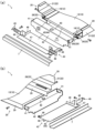
図1~図12は、本実施形態に係るパネル装置の一例及びパネルの変形例並びに同パネル装置を用いたパネル設置構造の一例及び変形例を模式的に示す図である。
An embodiment of the present invention will be described below with reference to the drawings.
Some of the detailed reference numerals attached to other drawings are omitted in some of the drawings.
In the following embodiments, directions such as the vertical direction will be described with reference to a state in which an example of the panel device according to the present embodiment is constructed.
1 to 12 are diagrams schematically showing an example of a panel device according to the present embodiment, a modification of the panel, and an example and a modification of a panel installation structure using the same panel device.
本実施形態に係るパネル装置1は、図3及び図4に示すように、第1方向に長尺で第2方向に間隔を空けた位置に配される天井下地を構成するフレーム20を備えている。パネル装置1は、このフレーム20に第2方向の端部12が保持されるパネルを構成する設備機器取付用パネル10を備えている。このパネル装置1は、住居やオフィス等の比較的に小型の建物の天井として施工されてもよく、体育館やホール、ショッピングモール、工場、学校等の比較的に大型の各種の建物の天井として施工されてもよい。
As shown in FIGS. 3 and 4, the panel device 1 according to the present embodiment includes a frame 20 that is elongated in a first direction and arranged at positions spaced apart in a second direction. there is The panel device 1 includes an equipment mounting panel 10 that constitutes a panel whose end portion 12 in the second direction is held by the frame 20 . This panel device 1 may be constructed as the ceiling of relatively small buildings such as residences and offices, and constructed as the ceiling of various relatively large buildings such as gymnasiums, halls, shopping malls, factories, and schools. may be
このパネル装置1を用いたパネル設置構造は、図1及び図2に示すように、吊部材2に吊下保持された天井下地(7,20)に天井パネル9及び第1方向に長尺な設備機器取付用パネル10が設置されている。このパネル設置構造においては、図4(a)、(b)に示すように、設備機器取付用パネル10は、天井パネル9よりも上方側に位置するように設置されている。このような構成とすれば、設備機器取付用パネル10に設備機器8が室内側に向けて突出するように設置される場合にも、天井パネル9からの設備機器8の突出量を小さくすることができ、見栄えを向上させることができる。このパネル設置構造においては、設備機器取付用パネル10の第1方向に直交する第2方向両側の天井パネル9は、設備機器取付用パネル10の第2方向の各端部12,12の室内側を覆うように設置されている。このような構成とすれば、第2方向両側の天井パネル9,9によって設備機器取付用パネル10の第2方向の各端部12,12が覆われるので、これらの間に天井バーが大きく露出するようなものと比べて、見栄えを向上させることができる。
As shown in FIGS. 1 and 2, the panel installation structure using this panel device 1 includes a ceiling panel 9 on a ceiling base (7, 20) suspended and held by a suspension member 2, and a ceiling panel 9 elongated in the first direction. An equipment mounting panel 10 is installed. In this panel installation structure, as shown in FIGS. 4A and 4B, the equipment installation panel 10 is installed above the ceiling panel 9 . With such a configuration, even when the equipment 8 is installed on the equipment mounting panel 10 so as to protrude toward the indoor side, the amount of projection of the equipment 8 from the ceiling panel 9 can be reduced. can improve the appearance. In this panel installation structure, the ceiling panels 9 on both sides of the equipment mounting panel 10 in the second direction orthogonal to the first direction are located on the indoor side of the equipment mounting panel 10 at the ends 12, 12 of the equipment mounting panel 10 in the second direction. installed to cover the With such a configuration, the ends 12, 12 of the equipment mounting panel 10 in the second direction are covered by the ceiling panels 9, 9 on both sides in the second direction, so that the ceiling bar is largely exposed between them. You can improve the appearance compared to what you would do.
設備機器取付用パネル10は、天井下地を構成し第1方向に延びるフレーム20に保持されている。このような構成とすれば、第1方向に長尺な設備機器取付用パネル10を第1方向に延びるフレーム20によって安定的に保持することができる。
この設備機器取付用パネル10の第2方向の各端部12,12は、第2方向に間隔を空けて配され、天井下地を構成し第1方向に延びる一対のフレーム20,20のそれぞれに固定されている。このような構成とすれば、吊部材2に吊下保持された一対のフレーム20,20に設備機器取付用パネル10の第2方向の各端部12,12が固定されてこれらが一体化されるので設備機器取付用パネル10を安定的に設置することができる。
The equipment mounting panel 10 is held by a frame 20 that constitutes a ceiling base and extends in the first direction. With such a configuration, the equipment mounting panel 10 elongated in the first direction can be stably held by the frame 20 extending in the first direction.
Each end 12, 12 in the second direction of the equipment mounting panel 10 is arranged in the second direction with a gap therebetween, and is attached to a pair of frames 20, 20 that form a ceiling base and extend in the first direction. Fixed. With such a configuration, the ends 12, 12 of the equipment mounting panel 10 in the second direction are fixed to the pair of frames 20, 20 suspended and held by the suspension member 2, and these are integrated. Therefore, the equipment mounting panel 10 can be stably installed.
フレーム20は、吊部材2に吊下保持される。フレーム20は、図3に示すように、第1方向に長尺で第2方向に間隔を空けて配され、設備機器取付用パネル10の第2方向の各端部12,12を保持する一対のパネル保持部25,25を備えている。フレーム20は、これらパネル保持部25,25のそれぞれに連なるように設けられ、吊部材2の引掛片4aが挿通される挿通孔24が第1方向に間隔を空けて複数箇所に設けられた一対の被吊下部21,21を備えている。このような構成とすれば、これら被吊下部21,21の挿通孔24,24に吊部材2,2の引掛片4a,4aを挿通することで設備機器取付用パネル10を保持するパネル保持部25,25を吊下げることができ、施工性を向上させることができる。
The frame 20 is suspended and held by the suspending member 2 . As shown in FIG. 3, the frames 20 are long in the first direction and spaced apart in the second direction. panel holding portions 25, 25 are provided. The frame 20 is provided so as to be connected to each of the panel holding portions 25, 25, and a pair of insertion holes 24 through which the hooking pieces 4a of the suspension member 2 are inserted are provided at a plurality of locations spaced apart in the first direction. suspended parts 21, 21. With such a configuration, the panel holding portion holds the equipment mounting panel 10 by inserting the hooking pieces 4a, 4a of the suspension members 2, 2 into the insertion holes 24, 24 of the suspended portions 21, 21. 25, 25 can be hung, and workability can be improved.
パネル装置1は、これら被吊下部21,21及びパネル保持部25,25をそれぞれに有し、第2方向に間隔を空けて配される一対の天井下地を構成するフレーム20,20を備えている。このような構成とすれば、設備機器取付用パネル10を保持する一対のパネル保持部25,25及び一対の被吊下部21,21が、例えば、コ字状の連結部を介して一体的に設けられた構成と比べて、個別に吊下位置を微調整して各フレーム20,20を吊下げることができる。これら一対のフレーム20,20は、互いに同様の構成であるので、以下では、具体的構成の一例について、一方のフレーム20を例にとって説明する。
パネル装置1は、設備機器取付用パネル10の第2方向両側に配される天井パネル9,9を備えている。このような構成とすれば、種々の設備機器8が取り付けられる設備機器取付用パネル10と天井パネル9とによって天井を構成することができる。
The panel device 1 includes frames 20, 20 each having these suspended parts 21, 21 and panel holding parts 25, 25, and constituting a pair of ceiling bases arranged with a gap in the second direction. there is With such a configuration, the pair of panel holding portions 25, 25 and the pair of suspended portions 21, 21 holding the equipment mounting panel 10 are integrally connected via, for example, a U-shaped connecting portion. Each frame 20, 20 can be suspended with fine adjustment of the suspension position individually compared to the arrangement provided. Since the pair of frames 20, 20 have the same configuration, an example of a specific configuration will be described below by taking one frame 20 as an example.
The panel device 1 includes ceiling panels 9, 9 arranged on both sides of the equipment mounting panel 10 in the second direction. With such a configuration, the ceiling can be configured by the equipment mounting panel 10 and the ceiling panel 9 to which various equipment 8 are mounted.
パネル装置1は、設備機器取付用パネル10の第2方向両側において第1方向に間隔を空けて、かつ第2方向に延びるように配され、天井パネル9,9を保持する野縁7,7を備えている。パネル装置1は、パネル保持部25及び被吊下部21と平行状に配され、野縁7を保持する野縁受6を備えている。このパネル装置1を用いたパネル設置構造は、設備機器取付用パネル10の第2方向両側の天井パネル9,9が、フレーム20と平行状に配された野縁受6に支持されて天井下地を構成し第2方向に延びる野縁7に保持されている。このような構成とすれば、設備機器取付用パネル10を保持するパネル保持部25(フレーム20)が天井パネル9を保持する野縁7やこれを保持する野縁受6に干渉するようなことがない。また、天井パネル9及び設備機器取付用パネル10のそれぞれを、別の天井下地(野縁7及びパネル保持部25(フレーム20))に保持させることができる。つまり、天井パネル9を吊下げる野縁7及び野縁受6と設備機器取付用パネル10を吊下げるフレーム20とは、相互に依存することなく、言わば別吊りで設置される。つまりは、設備機器取付用パネル10の荷重が天井パネル9を吊下げる野縁7及び野縁受6に掛からない構成とされている。これにより、例えば、設備機器取付用パネル10を吊下げるフレーム20側のみに耐震補強を施すようなことも可能となる。
The panel device 1 is arranged on both sides of the equipment mounting panel 10 in the second direction with a gap in the first direction and extending in the second direction, and the ceiling panels 9, 9 are held. It has The panel device 1 includes a joist receiver 6 that is arranged parallel to the panel holding portion 25 and the suspended portion 21 and holds the joist 7 . In the panel installation structure using this panel device 1, the ceiling panels 9, 9 on both sides of the equipment mounting panel 10 in the second direction are supported by the ceiling joists 6 arranged in parallel with the frame 20, and the ceiling foundation is installed. and is held by the joist 7 extending in the second direction. With such a configuration, the panel holding portion 25 (frame 20) holding the equipment mounting panel 10 does not interfere with the joist 7 holding the ceiling panel 9 and the joist receiver 6 holding it. There is no Also, the ceiling panel 9 and the equipment mounting panel 10 can be held by separate ceiling bases (the ceiling joist 7 and the panel holding portion 25 (frame 20)). In other words, the joist 7 and the joist receiver 6 from which the ceiling panel 9 is suspended and the frame 20 from which the facility equipment mounting panel 10 is suspended are installed separately, so to speak, without being dependent on each other. In other words, the load of the equipment mounting panel 10 is not applied to the joist 7 and the joist receiver 6 from which the ceiling panel 9 is suspended. As a result, for example, it is possible to apply seismic reinforcement only to the frame 20 side from which the equipment mounting panel 10 is suspended.
パネル装置1は、図1に示すように、第1方向及び第2方向に間隔を空けて複数箇所に配され、野縁受6及び被吊下部21をそれぞれに保持する吊部材2を備えている。このような構成とすれば、野縁受6を保持する一般的な吊部材2によって設備機器取付用パネル10を保持する被吊下部21を保持させることができる。つまりは、天井パネル9を保持する吊部材2と設備機器取付用パネル10を保持する吊部材2とを共通部品とすることができる。
吊部材2は、吊元となる上層のスラブや鉄骨等の躯体に第1方向及び第2方向に間隔を空けて複数箇所に設けられたインサート等の雌ねじ部材にねじ合わされ、第1方向及び第2方向に直交する上下方向に延びるように配される吊ボルト3を備えている。吊部材2は、この吊ボルト3に対して上下位置調整可能に保持されるハンガー4を備えている。
The panel device 1, as shown in FIG. there is With such a configuration, it is possible to hold the suspended portion 21 that holds the facility equipment mounting panel 10 by the general hanging member 2 that holds the joist support 6 . In other words, the suspending member 2 holding the ceiling panel 9 and the suspending member 2 holding the equipment mounting panel 10 can be used as common parts.
The suspending member 2 is screwed to a female screw member such as an insert provided at a plurality of locations in a first direction and a second direction on a frame such as an upper slab or a steel frame that is a suspending base. Hanging bolts 3 are arranged so as to extend in the vertical direction orthogonal to two directions. The suspension member 2 has a hanger 4 held so as to be vertically adjustable with respect to the suspension bolt 3 .
ハンガー4は、図5に示すように、吊ボルト3が挿通される挿通孔が設けられた被保持片部と、この被保持片部から垂れ下がるように設けられた垂下片部と、を備えている。引掛片4aは、この垂下片部の下端部に設けられた底片部から上方側に向けて屈曲するように設けられている。このハンガー4は、第1方向に見て、上向き開口の略U字状(略コ字状)とされている。図例では、引掛片4aの上端側部位には、開口を狭めるように屈曲された部位が設けられ、その内側に抜止突起が設けられている。引掛片4aの上端部は、開口を拡開させる傾斜形状とされている。このハンガー4は、被保持片部の上下に設けられ、吊ボルト3にねじ合わされたナットによって挟み込まれるようにして吊ボルト3に対して固定される。図1及び図3に示すように、複数のハンガー4のうちのいくつかには、図示省略のブレースの下端が取り付けられるブレース取付具5が取り付けられている。
このハンガー4を含む吊部材2としては、上記のような構成に限られず、吊天井の天井下地の吊部材として用いられる公知の吊部材でもよく、その他、種々の構成とされていてもよい。
As shown in FIG. 5, the hanger 4 includes a held piece portion provided with an insertion hole through which the suspension bolt 3 is inserted, and a hanging piece portion provided so as to hang down from the held piece portion. there is The hooking piece 4a is provided so as to bend upward from a bottom piece provided at the lower end of the hanging piece. The hanger 4 is generally U-shaped (substantially U-shaped) with an upward opening when viewed in the first direction. In the illustrated example, the hooking piece 4a is provided at its upper end portion with a portion bent to narrow the opening, and a retaining projection is provided inside thereof. The upper end of the hooking piece 4a has an inclined shape that widens the opening. The hanger 4 is provided above and below the piece to be held, and is fixed to the suspension bolt 3 so as to be sandwiched between nuts screwed onto the suspension bolt 3 . As shown in FIGS. 1 and 3, some of the plurality of hangers 4 are attached with brace fixtures 5 to which lower ends of braces (not shown) are attached.
The suspending member 2 including the hanger 4 is not limited to the configuration described above, and may be a known suspending member used as a suspending member for a ceiling base of a suspended ceiling, or may have various other configurations.
野縁受6は、第1方向に長尺で第2方向に間隔を空けて複数箇所に配され、鋼製天井下地(軽天下地)を構成する。この野縁受6は、横向きに開口する溝形鋼状(チャンネル状)とされていてもよい。この野縁受6は、引掛片4aの弾性変形を伴ってハンガー4の上方開口を介して差し込まれるようにしてハンガー4に取り付けられ、ねじ等の固着具によって固定されてもよい。上記したハンガー4の底片部から抜止突起までの上下方向に沿う寸法は、野縁受6の同方向に沿う寸法と略同寸法とされている。ハンガー4の垂下片部と引掛片4aの下端側部位との間の第2方向に沿う寸法は、野縁受6の同方向に沿う寸法と略同寸法とされている。鋼製天井下地は、第1方向に隣接する野縁受6,6同士を接合する野縁受ジョイントを備えていてもよい。
The joist supports 6 are elongated in the first direction and arranged at a plurality of locations at intervals in the second direction to form a steel ceiling base (light ceiling base). The joist support 6 may be in the shape of a channel steel (channel shape) that opens sideways. The joist receiver 6 may be attached to the hanger 4 so as to be inserted through the upper opening of the hanger 4 with elastic deformation of the hooking piece 4a, and fixed by a fastener such as a screw. The dimension along the vertical direction from the bottom piece of the hanger 4 to the retaining projection is substantially the same as the dimension along the same direction of the joist support 6 . The dimension along the second direction between the hanging piece portion of the hanger 4 and the lower end side portion of the hooking piece 4a is substantially the same as the dimension along the same direction of the joint receiver 6 . The steel ceiling base may be provided with a ceiling joist joint that joins the ceiling joists 6, 6 adjacent to each other in the first direction.
野縁7は、第2方向に長尺で第1方向に間隔を空けて複数箇所に配され、鋼製天井下地(軽天下地)を構成する。野縁7は、設備機器取付用パネル10が施工される箇所を囲むように、設備機器取付用パネル10が施工される箇所の第2方向両側及び必要に応じて第1方向両側のうちの少なくとも一方側に配される。換言すれば、設備機器取付用パネル10は、野縁7が配されない箇所に、野縁7に代えて配されるフレーム20に保持される。この野縁7は、上向きに開口する溝形鋼状(チャンネル状)とされていてもよく、また、両側壁上端に折り返されるように形成されたリップ部を設けた構成とされていてもよい。この野縁7は、適宜、公知のクリップを介して野縁受6に保持されてもよい。鋼製天井下地は、第2方向に隣接する野縁7,7同士を接合する野縁ジョイントを備えていてもよい。天井パネル9を保持する天井下地としては、このような野縁7に代えて、下端に天井パネル9の端部が載置される鍔部を有したいわゆるTバーでもよい。
The joists 7 are elongated in the second direction and arranged at a plurality of locations at intervals in the first direction to form a steel ceiling base (light ceiling base). The joist 7 surrounds the location where the equipment mounting panel 10 is constructed, so that the equipment mounting panel 10 is constructed on both sides in the second direction and, if necessary, on both sides in the first direction. placed on one side. In other words, the equipment mounting panel 10 is held by the frame 20 arranged instead of the ceiling joist 7 at a location where the ceiling joist 7 is not arranged. The joist 7 may be in the shape of a channel steel (channel-shaped) that opens upward, or may be configured with a lip portion formed so as to be folded back on the upper ends of both side walls. . The joist 7 may be appropriately held by the joist receiver 6 via a known clip. The steel ceiling substrate may have a ceiling joint that joins the ceiling joists 7, 7 adjacent in the second direction. Instead of the joist 7, a so-called T-bar having a flange on which the end of the ceiling panel 9 is placed at the lower end may be used as the ceiling base for holding the ceiling panel 9. As shown in FIG.
天井パネル9は、平面視して(厚さ方向に見て)、略方形状とされている。図例では、天井パネル9は、第1方向がパネル幅方向とされ、第2方向がパネル長手方向とされている。
この天井パネル9は、第1方向の各端部が第1方向に間隔を空けて設けられた野縁7,7に保持される。天井パネル9は、第1方向の各端部が直接的に野縁7,7に対してねじ等の固着具によって固定されてもよく、第1方向の各端部に取り付けられた固定部材や引掛部材等を介して野縁7,7に固定されてもよい。この天井パネル9の第1方向に沿う寸法、つまり、幅寸法は、野縁7,7のピッチに応じた寸法であってもよく、例えば、300mm~1200mm程度であってもよい。この天井パネル9の第2方向に沿う寸法、つまり、長さ寸法は、600mm~2000mm程度であってもよい。天井パネル9の厚さ寸法は、例えば、3.0mm~20.0mm程度であってもよい。
この天井パネル9は、石膏ボードやけい酸カルシウム板、ロックウールボード等の公知の天井材でもよく、発泡樹脂系または繊維系の基材を含み、難燃層や繊維強化樹脂層等の補強層が積層された構成でもよい。この天井パネル9及び鋼製天井下地を含む天井構造体の単位面積(1m2)当たりの質量が2.0kg以下となるように天井パネル9及び鋼製天井下地を適宜の質量としてもよい。
The ceiling panel 9 has a substantially rectangular shape in plan view (when viewed in the thickness direction). In the illustrated example, the first direction of the ceiling panel 9 is the panel width direction, and the second direction is the panel longitudinal direction.
The ceiling panel 9 is held at each end in the first direction by joists 7, 7 spaced apart in the first direction. The ceiling panel 9 may be fixed at each end in the first direction directly to the joists 7, 7 by fasteners such as screws, and fixing members attached to each end in the first direction, It may be fixed to the joists 7, 7 via a hook member or the like. The dimension along the first direction of the ceiling panel 9, that is, the width dimension may be a dimension corresponding to the pitch of the joists 7, 7, and may be, for example, about 300 mm to 1200 mm. The dimension along the second direction of the ceiling panel 9, that is, the length dimension may be about 600 mm to 2000 mm. The thickness dimension of the ceiling panel 9 may be, for example, about 3.0 mm to 20.0 mm.
This ceiling panel 9 may be a known ceiling material such as a gypsum board, a calcium silicate board, a rock wool board, etc., and includes a base material of a foamed resin system or a fiber system, and a reinforcing layer such as a flame retardant layer or a fiber reinforced resin layer. may be laminated. The mass of the ceiling panel 9 and the steel ceiling base may be set appropriately so that the mass per unit area (1 m 2 ) of the ceiling structure including the ceiling panel 9 and the steel ceiling base is 2.0 kg or less.
フレーム20は、第2方向に互いに間隔を空けて対向するように配される野縁7,7の間に位置するように、かつ長手方向が野縁7の長手方向に直交するように配される。このフレーム20は、全長に亘って概ね一様な形状とされている。このフレーム20の挿通孔24は、図3に示すように、引掛片4aの引掛位置を第1方向に調整可能なように第1方向に延びる長孔である。このような構成とすれば、吊部材2の引掛片4aの引掛位置を第1方向に位置調整して被吊下部21を吊下げることができる。この挿通孔24の第2方向に沿う短径は、第2方向が厚さ方向となる引掛片4aの厚さ寸法に応じた寸法とされている。この挿通孔24の短径は、引掛片4aに設けられた抜止突起の部分の挿通が可能なように適宜の寸法とされている。この挿通孔24の長径は、引掛片4aの引掛位置の第1方向への必要な調整代に応じて、また強度上の観点等から適宜の寸法としてもよい。この挿通孔24の長径は、例えば、引掛片4aの第1方向に沿う幅寸法の1.5倍~5倍程度であってもよい。
The frame 20 is arranged so as to be positioned between the joists 7, 7 which are arranged to face each other with a space in the second direction, and the longitudinal direction thereof is perpendicular to the longitudinal direction of the joist 7. be. The frame 20 has a generally uniform shape over its entire length. The insertion hole 24 of the frame 20 is, as shown in FIG. 3, an elongated hole extending in the first direction so that the hooking position of the hooking piece 4a can be adjusted in the first direction. With such a configuration, the suspended portion 21 can be suspended by adjusting the hooking position of the hooking piece 4a of the suspending member 2 in the first direction. The short diameter along the second direction of the insertion hole 24 is set according to the thickness dimension of the hooking piece 4a whose thickness direction is the second direction. The short diameter of the insertion hole 24 is set to an appropriate size so that the retaining projection provided on the hooking piece 4a can be inserted. The long diameter of the insertion hole 24 may be set to an appropriate dimension in accordance with the necessary adjustment margin for the hooking position of the hooking piece 4a in the first direction and from the viewpoint of strength and the like. The long diameter of the insertion hole 24 may be, for example, about 1.5 to 5 times the width dimension along the first direction of the hooking piece 4a.
フレーム20は、図4(a)、(b)に示すように、設備機器取付用パネル10の第2方向の端部12が載置される載置部を構成する載置片部27を備えている。このような構成とすれば、設備機器取付用パネル10の第2方向の端部12を載置片部27に載置して保持(仮保持)させることができるので、作業者に掛かる負荷を軽減することができる。この載置片部27は、厚さ方向が上下方向となるように配される略帯板状とされている。この載置片部27の厚さ寸法は、強度上の観点や軽量化を図る観点等から適宜の寸法としてもよい。この載置片部27の第2方向に沿う幅寸法は、設備機器取付用パネル10の第2方向の端部12の載置が可能なように適宜の寸法としてもよい。
As shown in FIGS. 4(a) and 4(b), the frame 20 includes a mounting piece portion 27 forming a mounting portion on which the end portion 12 of the equipment mounting panel 10 in the second direction is mounted. ing. With such a configuration, the end portion 12 in the second direction of the equipment mounting panel 10 can be placed and held (temporarily held) on the placing piece portion 27, so that the load on the worker can be reduced. can be mitigated. The mounting piece portion 27 has a substantially strip-like shape arranged so that the thickness direction thereof is the vertical direction. The thickness dimension of the mounting piece portion 27 may be an appropriate dimension from the viewpoint of strength, weight reduction, and the like. The width dimension along the second direction of the mounting piece portion 27 may be an appropriate dimension so that the end portion 12 of the equipment mounting panel 10 in the second direction can be mounted.
フレーム20は、第1方向に隣接するフレーム20と連結された状態で、互いの載置片部27,27同士が当接し、かつ互いの載置片部27,27よりも上方側部位同士の間に隙間が形成されるように、上方側部位よりも載置片部27,27が第1方向に突出している。このような構成とすれば、図8(c)に示すように、第1方向に隣接するフレーム20,20同士が連結された際に室内側において目立ち易くなる傾向がある載置片部27,27同士を効果的に当接させることができ、見栄えを向上させることができる。つまり、加工誤差等が生じた場合にも、上方側部位よりも載置片部27,27が第1方向に突出しているので、これら載置片部27,27よりも上方側となる上方側部位同士が当接して載置片部27,27間に隙間が形成されるようなことを抑制することができる。
The frame 20 is connected to the frame 20 adjacent in the first direction, and the mounting pieces 27, 27 are in contact with each other, and the portions above the mounting pieces 27, 27 are arranged. The mounting pieces 27, 27 protrude in the first direction from the upper portion so that a gap is formed therebetween. With such a configuration, as shown in FIG. 8C, when the frames 20, 20 adjacent to each other in the first direction are connected, the placing pieces 27 and 27 tend to be conspicuous inside the room. 27 can be brought into effective contact with each other, and the appearance can be improved. That is, even if a processing error or the like occurs, since the mounting piece portions 27, 27 protrude in the first direction from the upper portion, the upper side above the mounting piece portions 27, 27 is formed. Formation of a gap between the mounting pieces 27, 27 due to contact between the parts can be suppressed.
本実施形態では、パネル設置構造は、第1方向に隣接するフレーム20,20同士の連結部と、これらフレーム20,20に保持される第1方向に隣接する設備機器取付用パネル10,10同士の突き合わせ部と、が第1方向で異なる位置となるように設置されている。このような構成とすれば、第1方向に隣接するフレーム20,20同士の連結部と第1方向に隣接する設備機器取付用パネル10,10同士の突き合わせ部とが第1方向で同じ位置になる構造と比べて、真直性を確保することができる。これにより、載置片部27,27間の隙間をより効果的に生じ難くすることができる。つまり、フレーム20,20及び設備機器取付用パネル10,10のうちのいずれか一方によって他方の真直性を確保することができ、連結部及び突き合わせ部において隙間が生じるようなことを抑制することができる。同パネル設置構造においては、第2方向両側における第1方向に隣接するフレーム20,20同士の連結部は、第1方向で互いに一致した位置となるように設けられている。同パネル設置構造においては、長さ寸法が設備機器取付用パネル10の長さ寸法の整数倍とされたフレーム20,20同士の連結部が設備機器取付用パネル10の長手方向略中央部に位置するように設置してもよい。例えば、設備機器取付用パネル10の長さ寸法とフレーム20の長さ寸法とを略同寸法としてもよい。この場合、フレーム20の長手方向中央部に、第1方向に隣接する設備機器取付用パネル10,10の突き合わせ部の目印となる目印部が設けられていてもよい。
In the present embodiment, the panel installation structure consists of a connecting portion between the frames 20, 20 adjacent in the first direction, and equipment mounting panels 10, 10 held by the frames 20, 20 adjacent in the first direction. are installed so as to be different positions in the first direction. With such a configuration, the connecting portion between the frames 20, 20 adjacent in the first direction and the butting portion between the equipment mounting panels 10, 10 adjacent in the first direction are at the same position in the first direction. Straightness can be ensured compared with the structure which becomes. Thereby, the gap between the mounting pieces 27, 27 can be more effectively made difficult to occur. In other words, either one of the frames 20 and 20 and equipment mounting panels 10 and 10 can ensure the straightness of the other, and it is possible to suppress the occurrence of gaps at the connecting portions and butting portions. can. In the panel installation structure, the connecting portions between the frames 20, 20 adjacent in the first direction on both sides in the second direction are provided so as to be aligned with each other in the first direction. In the same panel installation structure, the connecting portion between the frames 20, 20 whose length dimension is an integer multiple of the length dimension of the equipment mounting panel 10 is positioned substantially at the center of the equipment mounting panel 10 in the longitudinal direction. You can set it to For example, the length dimension of the equipment mounting panel 10 and the length dimension of the frame 20 may be substantially the same. In this case, a mark portion may be provided in the longitudinal central portion of the frame 20 as a mark of the butted portion of the equipment mounting panels 10, 10 adjacent in the first direction.
フレーム20は、載置片部27から立ち上がるように設けられ、設備機器取付用パネル10の第2方向の端部12の端面に対向するように配される立上片部26を備えている。この立上片部26は、設備機器取付用パネル10の第2方向の端部12の端面に対向し設備機器取付用パネル10を固定する固着具が貫通する固定片部を構成する。このような構成とすれば、設備機器取付用パネル10を、固着具を介してフレーム20に固定することができる。この立上片部26及び載置片部27は、パネル保持部25を構成する。
この立上片部26は、載置片部27の第2方向外側(設備機器取付用パネル10の第2方向外側)縁部から立ち上がるように設けられ、厚さ方向が第2方向となるように配される略帯板状とされている。換言すれば、第2方向に間隔を空けて配される一対のフレーム20,20の各立上片部26,26の下端縁部から互いに向き合う方向に向けて突出するように載置片部27,27が設けられている。
The frame 20 is provided so as to rise from the mounting piece portion 27 and has a rising piece portion 26 arranged to face the end surface of the end portion 12 of the equipment mounting panel 10 in the second direction. The rising piece 26 constitutes a fixing piece through which a fastener for fixing the equipment mounting panel 10 faces the end face of the equipment mounting panel 10 in the second direction. With such a configuration, the equipment mounting panel 10 can be fixed to the frame 20 via the fasteners. The rising piece portion 26 and the mounting piece portion 27 constitute the panel holding portion 25 .
The rising piece portion 26 is provided so as to rise from the second direction outer side (the second direction outer side of the equipment mounting panel 10) edge of the mounting piece portion 27, and the thickness direction is the second direction. It has a substantially strip shape that is arranged in the In other words, the mounting piece portion 27 protrudes in the direction facing each other from the lower edge portions of the rising piece portions 26, 26 of the pair of frames 20, 20 spaced apart in the second direction. , 27 are provided.
この立上片部26の厚さ寸法は、強度上の観点や軽量化を図る観点等から適宜の寸法としてもよく、載置片部27と同厚さでもよい。この立上片部26の上下方向に沿う幅寸法は、設備機器取付用パネル10を固定する固着具の貫通が可能なように適宜の寸法としてもよく、設備機器取付用パネル10の厚さ寸法よりも大としてもよい。
この立上片部26は、載置片部27よりも上方側となる上方側部位を構成する。つまり、立上片部26は、図8(b)に示すように、第1方向に隣接するフレーム20,20の載置片部27,27同士が当接した状態で、第1方向に隣接する立上片部26との間に隙間が形成されるように配される。換言すれば、立上片部26は、その第1方向の各端部が載置片部27の第1方向の各端部よりも第1方向内側に位置するように形成されている。この立上片部26よりも第1方向に突出する載置片部27の突出寸法は、加工誤差等によって第1方向に隣接する立上片部26,26同士が当接しないように適宜の寸法としてもよい。
The thickness dimension of the rising piece portion 26 may be an appropriate dimension from the viewpoint of strength, weight reduction, or the like, and may be the same thickness as the mounting piece portion 27 . The width dimension along the vertical direction of the rising piece portion 26 may be an appropriate dimension so that the fixture for fixing the equipment mounting panel 10 can pass through, and the thickness dimension of the equipment mounting panel 10 may be greater than
The rising piece portion 26 constitutes an upper portion located above the placing piece portion 27 . That is, as shown in FIG. 8(b), the rising piece portion 26 is adjacent in the first direction while the mounting piece portions 27, 27 of the frames 20, 20 adjacent in the first direction are in contact with each other. It is arranged so that a gap is formed between the rising piece portion 26 and the rising piece portion 26 . In other words, the rising piece 26 is formed such that each end in the first direction is positioned more inward in the first direction than each end of the placing piece 27 in the first direction. The projecting dimension of the mounting piece portion 27 projecting in the first direction from the rising piece portion 26 is appropriately determined so that the rising piece portions 26, 26 adjacent in the first direction do not come into contact with each other due to processing errors or the like. It may be dimensioned.
フレーム20の被吊下部21には、この立上片部26の上端部から第2方向外側に延出し挿通孔24が設けられた被引掛片部23が設けられている。このような構成とすれば、この被引掛片部23、立上片部26及び載置片部27によって少なくともZ字状となり、例えば、L字状の構成と比べて、パネル保持部25及び被吊下部21の強度を向上させることができる。
被引掛片部23は、厚さ方向が上下方向となるように配される略帯板状とされている。挿通孔24は、被引掛片部23を厚さ方向に貫通して形成されている。この被引掛片部23の第2方向に沿う幅寸法は、挿通孔24の形成が可能なように、また、軽量化を図る観点等から適宜の寸法としてもよい。
被吊下部21には、この被引掛片部23の第2方向外側縁部から立ち上がるように設けられ、ハンガー4に固定される固定片部22が設けられている。この固定片部22は、厚さ方向が第2方向となるように配される略帯板状とされている。この固定片部22の上端部には、第2方向対向側(設備機器取付用パネル10の第2方向中心側、第2方向内側)に向けて突出する上端片部が設けられている。この上端片部は、厚さ方向が上下方向となるように配される略帯板状とされている。この上端片部、固定片部22及び被引掛片部23の厚さ寸法は、強度上の観点や軽量化を図る観点等から適宜の寸法としてもよく、立上片部26と同厚さでもよい。
The suspended portion 21 of the frame 20 is provided with a hooked piece portion 23 extending outward in the second direction from the upper end portion of the rising piece portion 26 and provided with an insertion hole 24 . With such a configuration, at least the hooked piece 23, the rising piece 26, and the placing piece 27 form a Z-shape. The strength of the suspended portion 21 can be improved.
The hooked piece portion 23 has a substantially strip shape arranged so that the thickness direction thereof is the vertical direction. The insertion hole 24 is formed through the hooked piece portion 23 in the thickness direction. The width dimension of the hooked piece portion 23 along the second direction may be an appropriate dimension so that the insertion hole 24 can be formed and from the viewpoint of weight reduction.
The suspended portion 21 is provided with a fixed piece portion 22 that is provided so as to rise from the second direction outer edge portion of the hooked piece portion 23 and that is fixed to the hanger 4 . The fixing piece portion 22 has a substantially strip-like shape arranged so that the thickness direction thereof is in the second direction. The upper end portion of the fixed piece portion 22 is provided with an upper end piece portion that protrudes toward the opposite side in the second direction (the center side in the second direction of the equipment mounting panel 10 and the inner side in the second direction). The upper end piece has a substantially strip-like shape arranged so that the thickness direction is the vertical direction. The thickness dimensions of the upper end piece portion, the fixed piece portion 22, and the hooked piece portion 23 may be set appropriately from the viewpoint of strength and weight reduction. good.
これら上端片部、固定片部22及び被引掛片部23を備えた被吊下部21は、横向きに開口する溝形鋼状(チャンネル状)とされている。この被吊下部21の上下方向に沿う寸法は、野縁受6の上下方向に沿う寸法と略同寸法とされている。被引掛片部23の固定片部22から挿通孔24までの第2方向に沿う寸法及び上端片部の同方向に沿う寸法は、野縁受6の下端片部及び上端片部の同方向に沿う寸法と略同寸法とされている。つまりは、野縁受6と共通の吊部材2によって吊下可能なように、被吊下部21の上端片部、固定片部22及び被引掛片部23の挿通孔24までの部位は、野縁受6と略同寸同形状とされている。
この被吊下部21は、載置片部27よりも上方側となる上方側部位を構成する。つまり、被吊下部21は、図8(a)~(c)に示すように、第1方向に隣接するフレーム20,20の載置片部27,27同士が当接した状態で、第1方向に隣接する被吊下部21との間に隙間が形成されるように配される。換言すれば、被吊下部21は、その第1方向の各端部が載置片部27の第1方向の各端部よりも第1方向内側に位置するように形成されている。
The suspended portion 21 including the upper end piece portion, the fixed piece portion 22 and the hooked piece portion 23 is formed in the shape of a channel steel (channel shape) that opens laterally. The vertical dimension of the suspended portion 21 is substantially the same as the vertical dimension of the joist support 6 . The dimension along the second direction from the fixed piece portion 22 of the hooked piece portion 23 to the insertion hole 24 and the dimension along the same direction of the upper end piece portion are the same direction of the lower end piece portion and the upper end piece portion of the joint receiver 6 It is assumed to be substantially the same dimension as the dimension along. In other words, the part up to the insertion hole 24 of the upper end piece part of the suspended part 21, the fixed piece part 22 and the hooked piece part 23 so that it can be hung by the common hanging member 2 with the joist receiver 6 It has substantially the same size and shape as the edge support 6 .
The suspended portion 21 constitutes an upper side portion that is located above the placing piece portion 27 . That is, as shown in FIGS. 8(a) to 8(c), the suspended portion 21 is in a state in which the mounting pieces 27, 27 of the frames 20, 20 adjacent in the first direction are in contact with each other. It is arranged so that a gap is formed between the suspended parts 21 adjacent in the direction. In other words, the suspended portion 21 is formed such that each end in the first direction is positioned more inward in the first direction than each end in the first direction of the mounting piece portion 27 .
図例では、被引掛片部23の第1方向の各端部には、立上片部26側部位よりも固定片部22側部位が第1方向内側となるように切欠状の凹段部が形成されている。被引掛片部23の立上片部26側部位の第1方向の各端部は、立上片部26の第1方向の各端部と第1方向で一致するように形成されている。被引掛片部23の固定片部22側部位の第1方向の各端部は、固定片部22の第1方向の各端部と第1方向で一致するように形成されている。換言すれば、第1方向に隣接する被引掛片部23,23の固定片部22側部位同士、固定片部22,22同士及び上端片部同士の隙間は、第1方向に隣接する立上片部26,26同士及び被引掛片部23,23の立上片部26側部位同士の隙間よりも大とされている。第1方向に隣接するフレーム20,20の載置片部27,27同士が当接され、かつ互いの載置片部27,27よりも上方側部位同士の間に隙間が形成される構成としては、このような構成に限られず、その他、種々の変形が可能である。
In the illustrated example, at each end of the hooked piece 23 in the first direction, a notch-shaped recessed step is provided so that the portion on the fixed piece 22 side is located more inward in the first direction than the portion on the side of the rising piece 26 . is formed. Each end in the first direction of the portion of the hooked piece 23 on the side of the rising piece 26 is formed to match each end in the first direction of the rising piece 26 in the first direction. Each end in the first direction of the hooked piece 23 on the side of the fixed piece 22 is formed to match each end in the first direction of the fixed piece 22 in the first direction. In other words, the clearances between the fixed piece portions 22 side portions of the hooked piece portions 23, 23 adjacent in the first direction, the fixed piece portions 22, 22, and the upper end piece portions It is larger than the gap between the pieces 26 and 26 and between the hooked pieces 23 and 23 on the rising piece 26 side. As a configuration in which the mounting pieces 27, 27 of the frames 20, 20 adjacent in the first direction are in contact with each other, and a gap is formed between the parts on the upper side of the mutual mounting pieces 27, 27. is not limited to such a configuration, and various other modifications are possible.
フレーム20には、図4(a)、(b)に示すように、室内側に延出し、第2方向両側の天井パネル9の端面9aに対向する延出片29が設けられている。このような構成とすれば、設備機器取付用パネル10の第2方向両側に配される天井パネル9,9の端面9a,9aを各フレーム20,20の延出片29,29によって目立ち難くすることができる。
この延出片29は、載置片部27の第2方向対向側縁部から垂れ下がるように設けられ、厚さ方向が第2方向となるように配される略帯板状とされている。天井パネル9の延出片29側の端部は、載置片部27の下方側に位置するように配される。
この延出片29の厚さ寸法は、強度上の観点や軽量化を図る観点等から適宜の寸法としてもよく、載置片部27と同厚さでもよい。この延出片29の上下方向に沿う幅寸法は、対向する天井パネル9の端面9aが目立ち難くなるように、また、軽量化を図る観点等から適宜の寸法としてもよい。この延出片29の上下方向に沿う幅寸法は、延出片29の下端が天井パネル9の下面(室内側面)と略同高さまたはそれよりも下方側に位置するように適宜の寸法としてもよい。この延出片29は、載置片部27の全長に亘って設けられている。つまり、図8(b)に示すように、第1方向に隣接するフレーム20,20の載置片部27,27同士が当接した状態で、それぞれの延出片29,29同士も当接する構成とされている。
フレーム20は、野縁7や野縁受6と同様、種々の金属系材料から形成された鋼製であってもよい。
As shown in FIGS. 4(a) and 4(b), the frame 20 is provided with extension pieces 29 that extend into the room and face the end surfaces 9a of the ceiling panels 9 on both sides in the second direction. With such a configuration, the end surfaces 9a, 9a of the ceiling panels 9, 9 arranged on both sides in the second direction of the equipment mounting panel 10 are made inconspicuous by the extension pieces 29, 29 of the respective frames 20, 20. be able to.
The extending piece 29 is provided so as to hang down from the side edge portion of the mounting piece portion 27 facing the second direction, and has a substantially strip shape arranged so that the thickness direction thereof is in the second direction. The end portion of the ceiling panel 9 on the side of the extension piece 29 is arranged to be positioned below the mounting piece portion 27 .
The thickness dimension of the extending piece 29 may be an appropriate dimension from the viewpoint of strength, weight reduction, or the like, and may be the same thickness as the mounting piece portion 27 . The width dimension of the extending piece 29 in the vertical direction may be set appropriately so that the end surface 9a of the ceiling panel 9 facing the ceiling panel 9 is less conspicuous and from the viewpoint of weight reduction. The width dimension of the extension piece 29 along the vertical direction is set appropriately so that the lower end of the extension piece 29 is positioned at approximately the same height as the lower surface (interior side surface) of the ceiling panel 9 or below it. good too. The extension piece 29 is provided over the entire length of the mounting piece portion 27 . That is, as shown in FIG. 8(b), when the mounting pieces 27, 27 of the frames 20, 20 adjacent in the first direction are in contact with each other, the extension pieces 29, 29 are also in contact with each other. It is configured.
The frame 20, like the joist 7 and the joist receiver 6, may be made of steel made of various metallic materials.
設備機器取付用パネル10は、第1方向に長尺な略方形平板状とされている。この設備機器取付用パネル10の第1方向に沿う長さ寸法は、例えば、600mm~2000mm程度であってもよい。図例では、設備機器取付用パネル10の第1方向に沿う長さ寸法は、天井パネル9の第1方向に沿う幅寸法の約2倍の寸法とされている(図1及び図2参照)。この設備機器取付用パネル10の第2方向に沿う幅寸法は、下面側に種々の設備機器8が設置される場合には、設備機器8の寸法に応じた寸法であってもよく、例えば、150mm~600mm程度であってもよい。この設備機器取付用パネル10の厚さ寸法は、天井パネル9の厚さ寸法と同程度であってもよい。
設備機器取付用パネル10は、図3及び図5に示すように、パネル本体13と、このパネル本体13の第2方向の各端部15,15の端面及び上面を覆うようにパネル本体13に取り付けられた端部保護部材16,16と、を備えている。このような構成とすれば、これら第2方向両側の端部保護部材16,16によってパネル本体13の第2方向の各端部15,15を保護することができる。
The equipment mounting panel 10 is in the shape of a substantially rectangular flat plate elongated in the first direction. The length dimension along the first direction of the equipment mounting panel 10 may be, for example, about 600 mm to 2000 mm. In the illustrated example, the length dimension along the first direction of the equipment mounting panel 10 is about twice the width dimension along the first direction of the ceiling panel 9 (see FIGS. 1 and 2). . The width dimension along the second direction of the equipment mounting panel 10 may be a dimension corresponding to the dimensions of the equipment 8 when various equipment 8 is installed on the lower surface side. It may be about 150 mm to 600 mm. The thickness dimension of the equipment mounting panel 10 may be approximately the same as the thickness dimension of the ceiling panel 9 .
As shown in FIGS. 3 and 5, the equipment mounting panel 10 includes a panel body 13, and the panel body 13 is attached to the panel body 13 so as to cover the end surfaces and the top surface of each of the ends 15, 15 in the second direction of the panel body 13. and attached edge protection members 16,16. With such a configuration, the ends 15, 15 of the panel main body 13 in the second direction can be protected by the end protection members 16, 16 on both sides in the second direction.
パネル装置1は、これら第2方向両側の端部保護部材16,16の上面側において跨るように設けられ、第2方向の各端部が一対のフレーム20,20のそれぞれに固定される浮上防止部材30を備えている。このような構成とすれば、設備機器取付用パネル10の第2方向の各端部12,12を保持する一対のフレーム20,20を、浮上防止部材30によって連結することができ、一対のフレーム20,20が離間するようなことを抑制することができる。浮上防止部材30によって設備機器取付用パネル10の浮き上がりを防止することができ、また、浮上防止部材30が端部保護部材16,16に当接されるので、パネル本体13が脆弱な場合にもパネル本体13の損傷を抑制することができる。つまり、浮上防止部材30に、一対のフレーム20,20同士の連結機能と設備機器取付用パネル10の浮上防止機能とを兼ね備えさせることができ、部品点数を削減することもできる。浮上防止部材30によって設備機器取付用パネル10の浮き上がりが防止されるので、設備機器取付用パネル10の設置後にパネル本体13に設備機器8を取り付けたり、孔加工を施したりする際における作業性を向上させることができる。浮上防止部材30の具体的構成の一例については後述する。
The panel device 1 is provided so as to straddle the upper surface sides of the end protection members 16, 16 on both sides in the second direction, and each end in the second direction is fixed to a pair of frames 20, 20, respectively. A member 30 is provided. With such a configuration, the pair of frames 20, 20 holding the ends 12, 12 of the equipment mounting panel 10 in the second direction can be connected by the anti-floating member 30. It is possible to prevent the 20, 20 from being separated from each other. The anti-floating member 30 can prevent the equipment mounting panel 10 from floating, and since the anti-floating member 30 abuts against the end protection members 16, 16, even when the panel body 13 is fragile. Damage to the panel body 13 can be suppressed. That is, the anti-floating member 30 can have both the function of connecting the pair of frames 20, 20 and the anti-floating function of the equipment mounting panel 10, and the number of parts can be reduced. Since the floating prevention member 30 prevents the equipment mounting panel 10 from floating, workability is improved when mounting the equipment 8 on the panel main body 13 after the equipment mounting panel 10 is installed, or performing hole processing. can be improved. An example of a specific configuration of the floating prevention member 30 will be described later.
パネル本体13は、第1方向に長尺な方形平板状とされている。このパネル本体13は、一般的に天井ボードとして用いられるボードであってもよい。このパネル本体13は、上記した天井パネル9と同様のパネル材から形成されていてもよく、または異なるパネル材から形成されていてもよい。このパネル本体13は、設備機器8の配設や配線等のために施工現場において容易に孔加工が可能なように、例えば、比較的に脆弱な石膏ボードやけい酸カルシウム板、発泡樹脂系ボード等であってもよい。このパネル本体13に設置される設備機器8としては、図例のような火災感知器に限られず、照明器具や音響機器、送風機、物干装置、収納装置等でもよく、その他、種々の設備機器でもよい。
The panel main body 13 has a rectangular flat plate shape elongated in the first direction. This panel body 13 may be a board generally used as a ceiling board. The panel body 13 may be formed from the same panel material as the ceiling panel 9 described above, or may be formed from a different panel material. The panel body 13 is made of, for example, a relatively fragile gypsum board, a calcium silicate board, or a foamed resin board so that holes can be easily drilled at the construction site for the arrangement and wiring of the equipment 8. etc. The equipment 8 installed on the panel main body 13 is not limited to the fire detector as shown in the figure, but may be lighting fixtures, audio equipment, air blowers, drying equipment, storage equipment, etc., and various other equipment. It's okay.
端部保護部材16は、フレーム20の載置片部27に載置される設備機器取付用パネル10の端部12を構成する。載置片部27及び端部保護部材16のうちの一方には、他方に設けられた係合突部28が差し込まれる係合凹部18が設けられている。このような構成とすれば、係合凹部18に係合突部28を差し込むことで、それぞれに吊部材2,2に吊下保持された一対のフレーム20,20の離間する方向への移動を設備機器取付用パネル10によって抑制することができる。このように移動が抑制された状態で、浮上防止部材30を固定することができるので、作業性を向上させることができる。また、載置片部27,27に載置して仮保持させた設備機器取付用パネル10が意図せずに落下するようなことを抑制することができる。本実施形態では、端部保護部材16に係合凹部18が設けられ、載置片部27に係合突部28が設けられている。載置片部27の係合突部28は、図5に示すように、載置片部27の第2方向途中部位の上面から上方側に向けて突出するように設けられている。この係合突部28は、図3に示すように、フレーム20の長手方向に間隔を空けて複数箇所に設けられている。この係合突部28は、厚さ方向が第2方向となるように配される略平板状とされ、フレーム20の長手方向となる第1方向に延びるように設けられている。図例では、係合突部28は、載置片部27に切り起こし状に設けられている。
The edge protection member 16 constitutes the edge 12 of the equipment mounting panel 10 mounted on the mounting piece 27 of the frame 20 . One of the mounting piece 27 and the end protection member 16 is provided with an engagement recess 18 into which an engagement projection 28 provided on the other is inserted. With such a configuration, by inserting the engaging protrusion 28 into the engaging recess 18, the pair of frames 20, 20 suspended and held by the suspending members 2, 2 can be moved in the direction away from each other. It can be suppressed by the equipment mounting panel 10 . Since the anti-floating member 30 can be fixed while its movement is suppressed in this manner, workability can be improved. In addition, it is possible to prevent the equipment mounting panel 10 temporarily held by being placed on the placing pieces 27 from falling unintentionally. In this embodiment, the end protection member 16 is provided with the engaging recess 18 , and the mounting piece 27 is provided with the engaging protrusion 28 . As shown in FIG. 5, the engaging projection 28 of the mounting piece 27 is provided to protrude upward from the upper surface of the middle portion of the mounting piece 27 in the second direction. As shown in FIG. 3, the engaging projections 28 are provided at a plurality of locations in the longitudinal direction of the frame 20 at intervals. The engaging protrusion 28 has a substantially flat plate shape arranged so that the thickness direction is the second direction, and is provided so as to extend in the first direction, which is the longitudinal direction of the frame 20 . In the illustrated example, the engaging protrusion 28 is provided in a cut-and-raised shape on the mounting piece portion 27 .
端部保護部材16は、図3に示すように、第1方向に長尺状とされ、設備機器取付用パネル10の略全長に亘って設けられている。第2方向両側の端部保護部材16,16は、互いに同様の構成とされているので、以下では、具体的構成の一例について、一方の端部保護部材16を例にとって説明する。
端部保護部材16は、全長に亘って一様な形状とされている。この端部保護部材16には、図5に示すように、パネル本体13の第2方向の端部15を受け入れる受入溝17が設けられている。この受入溝17は、パネル本体13の第2方向中央側に向けて開口し、端部保護部材16の全長に亘って延びるように設けられている。この受入溝17の上下方向に沿う溝幅寸法は、端部保護部材16をパネル本体13の端部15に固定する接着層の確保が可能なように、パネル本体13の厚さ寸法よりも大きい寸法でもよい。この受入溝17の第2方向に沿う溝深さ寸法は、パネル本体13の端部15の保持が可能なように、また、端部15を補強する観点や軽量化を図る観点等から適宜の寸法としてもよい。端部保護部材16には、受入溝17の溝幅方向一方側を区画しパネル本体13の端部15の上面を覆う上片部16bと、受入溝17の溝幅方向他方側を区画し端部15の下面を覆う下片部16cと、受入溝17の溝底を区画し端部15の端面を覆う側片部16dと、が設けられている。図例では、上片部16bの第2方向に沿う幅寸法を、下片部16cの第2方向に沿う幅寸法よりも大とした例を示しているが、このような例に限られない。
As shown in FIG. 3 , the end protection member 16 is elongated in the first direction and provided over substantially the entire length of the equipment mounting panel 10 . Since the end protection members 16, 16 on both sides in the second direction have the same configuration, an example of a specific configuration will be described below by taking one end protection member 16 as an example.
The edge protection member 16 has a uniform shape over its entire length. As shown in FIG. 5, the end protection member 16 is provided with a receiving groove 17 for receiving the end 15 of the panel body 13 in the second direction. The receiving groove 17 opens toward the center of the panel body 13 in the second direction and extends over the entire length of the end protection member 16 . The groove width dimension of the receiving groove 17 along the vertical direction is larger than the thickness dimension of the panel body 13 so that the adhesive layer for fixing the edge protection member 16 to the edge 15 of the panel body 13 can be secured. It can be dimension. The groove depth dimension of the receiving groove 17 along the second direction is appropriately selected so that the end portion 15 of the panel body 13 can be held, and from the viewpoint of reinforcing the end portion 15 and reducing the weight. It may be dimensioned. The end protection member 16 includes an upper piece 16b that defines one side of the receiving groove 17 in the groove width direction and covers the upper surface of the end portion 15 of the panel body 13, and an end portion that defines the other side of the receiving groove 17 in the groove width direction. A lower piece portion 16c that covers the lower surface of the portion 15 and a side piece portion 16d that partitions the groove bottom of the receiving groove 17 and covers the end surface of the end portion 15 are provided. The illustrated example shows an example in which the width dimension along the second direction of the upper piece portion 16b is larger than the width dimension along the second direction of the lower piece portion 16c, but is not limited to such an example. .
この端部保護部材16の係合凹部18は、受入溝17の第2方向外側に位置するように設けられている。この係合凹部18は、下方側に向けて開口し、端部保護部材16の全長に亘って延びるように溝状に形成されている。この係合凹部18の上下方向に沿う溝深さ寸法及び第2方向に沿う溝幅寸法は、上記した係合突部28の受け入れが可能なように適宜の寸法とされている。この係合凹部18の溝幅方向一方側は、端部保護部材16の側片部16dによって区画されている。係合凹部18の溝底は、側片部16dの上下方向途中部位から第2方向外側に延出する底片部によって区画されている。係合凹部18の溝幅方向他方側は、底片部の延出方向先端部から垂れ下がる外側片部によって区画されている。図例では、この外側片部の下端部から第2方向外側に向けて突出する下端突片部が設けられた例を示している。この下端突片部は、その下面(室内側面)が受入溝17を区画する下片部の下面(室内側面)と略同一平面状となるように設けられている。係合凹部18としては、上記のような構成に限られず、その他、種々の構成とされていてもよい。
The engaging recess 18 of the end protection member 16 is provided so as to be positioned outside the receiving groove 17 in the second direction. The engagement recess 18 is formed in a groove shape so as to open downward and extend over the entire length of the end protection member 16 . The groove depth dimension along the up-down direction and the groove width dimension along the second direction of the engaging recess 18 are appropriately set so that the engaging protrusion 28 can be received. One side of the engagement recess 18 in the groove width direction is defined by the side piece 16 d of the end protection member 16 . The groove bottom of the engaging recess 18 is defined by a bottom piece portion extending outward in the second direction from the middle portion of the side piece portion 16d in the vertical direction. The other side of the engaging recess 18 in the groove width direction is defined by an outer piece hanging down from the leading end of the bottom piece in the extending direction. The illustrated example shows an example in which a lower end protruding piece portion is provided that protrudes outward in the second direction from the lower end portion of the outer piece portion. The lower end projecting piece portion is provided so that its lower surface (indoor side surface) is substantially flush with the lower surface (indoor side surface) of the lower piece portion that defines the receiving groove 17 . The engaging recess 18 is not limited to the configuration described above, and may have various other configurations.
端部保護部材16には、立上片部26を貫通する固着具の軸部を受け入れる受入凹所19が設けられている(図7(a)、(b)も参照)。この受入凹所19は、第2方向外側(立上片部26側)に向けて開口し、端部保護部材16の全長に亘って延びるように溝状に形成されている。この受入凹所19の第2方向に沿う溝深さ寸法及び上下方向に沿う溝幅寸法は、立上片部26を貫通する固着具の軸部の受け入れが可能なように適宜の寸法とされている。この受入凹所19の溝幅方向一方側は、係合凹部18の溝底を区画する底片部によって区画されている。受入凹所19の溝底は、受入溝17の溝底を区画する側片部16d及びこれに連なるように上方側に向けて延出する延出側片部16eによって区画されている。受入凹所19の溝幅方向他方側は、延出側片部16eの延出方向先端部となる上端部から第2方向外側に向けて突出する上端突片部16fによって区画されている。図例では、延出側片部16eの上端部から第2方向内側に向けて突出する内側突片部16gが設けられた例を示している。この内側突片部16g及び上端突片部16fの上面が端部保護部材16の上面を構成する。
The end protection member 16 is provided with a receiving recess 19 for receiving the shaft portion of the fastener passing through the rising piece portion 26 (see also FIGS. 7(a) and 7(b)). The receiving recess 19 is formed in a groove shape so as to open outward in the second direction (to the rising piece 26 side) and extend over the entire length of the end protection member 16 . The depth of the groove in the second direction and the width of the groove in the vertical direction of the receiving recess 19 are set appropriately so that the shaft of the fastener passing through the rising piece 26 can be received. ing. One side of the receiving recess 19 in the groove width direction is defined by a bottom piece that defines the groove bottom of the engaging recess 18 . The groove bottom of the receiving recess 19 is defined by a side piece portion 16d that defines the groove bottom of the receiving groove 17 and an extension side piece portion 16e that extends upward so as to be connected to the side piece portion 16d. The other side of the receiving recess 19 in the groove width direction is defined by an upper end protruding piece 16f that protrudes outward in the second direction from the upper end serving as the leading end in the extending direction of the extending side piece 16e. The illustrated example shows an example in which an inner protruding piece portion 16g protruding inward in the second direction is provided from the upper end portion of the extension side piece portion 16e. The upper surfaces of the inner projecting piece 16g and the upper end projecting piece 16f constitute the upper surface of the end protection member 16. As shown in FIG.
この端部保護部材16は、適宜の固着具や接着剤、粘着材等によってパネル本体13の端部15に取り付けられていてもよい。または、端部保護部材16は、パネル本体13の端部15が受入溝17に嵌め込まれて(圧入されて)端部15に取り付けられていてもよい。このような固定態様に応じて、受入溝17の上下方向に沿う溝幅寸法は、パネル本体13の厚さ寸法と同寸法でもよく、パネル本体13の厚さ寸法よりも僅かに小さい寸法でもよい。この端部保護部材16は、金属系材料や硬質の合成樹脂系材料から形成された押出成形品でもよい。端部保護部材16としては、上記したような形状に限られず、その他、種々の形状とされていてもよく、少なくともパネル本体13の端部15の端面及び上面を覆う部位を有した形状とされていてもよい。
The edge protection member 16 may be attached to the edge 15 of the panel main body 13 by an appropriate fastener, adhesive, adhesive, or the like. Alternatively, the edge protection member 16 may be attached to the edge 15 by fitting (pressing) the edge 15 of the panel body 13 into the receiving groove 17 . Depending on such a fixing mode, the groove width dimension along the vertical direction of the receiving groove 17 may be the same dimension as the thickness dimension of the panel body 13, or may be a dimension slightly smaller than the thickness dimension of the panel body 13. . The edge protection member 16 may be an extruded product formed from a metal-based material or a hard synthetic resin-based material. The edge protection member 16 is not limited to the shape described above, and may have various other shapes. may be
浮上防止部材30は、図4(a)及び図5に示すように、第2方向両側のフレーム20,20を連結するように第2方向に長尺状とされている。この浮上防止部材30における平面視して略方形平板状とされた本体部の第2方向の各端部の下面が設備機器取付用パネル10の第2方向両側の端部保護部材16,16の上面に当接される。この浮上防止部材30の本体部の上面は、フレーム20の被引掛片部23の上面よりも下方側に位置するように配される。
この浮上防止部材30の第2方向の各端部には、第2方向両側の端部保護部材16,16のそれぞれの第2方向外側において垂れ下がるように配される垂下片32,32が設けられている。このような構成とすれば、浮上防止部材30を固定する際に浮上防止部材30に対して設備機器取付用パネル10が第2方向に移動するようなことを抑制することができる。上記したフレーム20の立上片部26は、この垂下片32の第2方向外側に位置するように配され、垂下片32に止着される固着具が貫通される固定片部を構成する。このような構成とすれば、立上片部26を貫通させて浮上防止部材30の垂下片32に固着具を止着して浮上防止部材30をフレーム20に固定することができる。
As shown in FIGS. 4A and 5, the anti-floating member 30 is elongated in the second direction so as to connect the frames 20, 20 on both sides in the second direction. The lower surface of each end in the second direction of the main body portion of the anti-floating member 30, which has a substantially rectangular flat plate shape in plan view, is attached to the end protection members 16, 16 on both sides of the equipment mounting panel 10 in the second direction. It abuts on the upper surface. The upper surface of the main body portion of the floating prevention member 30 is positioned below the upper surface of the hooked piece portion 23 of the frame 20 .
At each end in the second direction of the floating prevention member 30, hanging pieces 32, 32 are provided so as to hang down in the second direction outside of the end protection members 16, 16 on both sides in the second direction. ing. With such a configuration, it is possible to prevent the equipment mounting panel 10 from moving in the second direction with respect to the anti-floating member 30 when fixing the anti-floating member 30 . The rising piece portion 26 of the frame 20 described above is arranged so as to be positioned outside the hanging piece 32 in the second direction, and constitutes a fixing piece portion through which a fastener fixed to the hanging piece 32 penetrates. With such a configuration, the anti-floating member 30 can be fixed to the frame 20 by penetrating the rising piece portion 26 and fixing the fixture to the hanging piece 32 of the anti-floating member 30 .
これら垂下片32,32は、図4(a)に示すように、厚さ方向が第2方向となるように配される略平板状とされている。これら垂下片32,32は、第2方向両側のフレーム20,20の立上片部26,26の第2方向内側に沿うように配される。浮上防止部材30は、これら垂下片32,32に立上片部26,26の第2方向外側からこれらを貫通させた固着具が止着されてフレーム20,20に固定される。上記した端部保護部材16の受入凹所19は、この固着具の軸部の受け入れが可能なように設けられている。これら垂下片32,32は、それぞれの下端が端部保護部材16,16の下端突片部に近接するように配される。
これら垂下片32,32は、浮上防止部材30の本体部の第1方向の全体に亘って設けられている。これら垂下片32,32及び浮上防止部材30の本体部の第1方向に沿う寸法は、設備機器取付用パネル10の浮き上がりを防止する観点や軽量化を図る観点等から適宜の寸法としてもよい。
As shown in FIG. 4(a), these hanging pieces 32, 32 are formed in a substantially flat plate shape arranged so that the thickness direction is the second direction. These hanging pieces 32, 32 are arranged along the second direction inner side of the rising pieces 26, 26 of the frames 20, 20 on both sides in the second direction. The anti-floating member 30 is fixed to the frames 20 , 20 by attaching fasteners passing through the hanging pieces 32 , 32 from the outside of the rising pieces 26 , 26 in the second direction. The receiving recess 19 of the end protection member 16 described above is provided so as to be able to receive the shaft of this fixture. These hanging pieces 32 , 32 are arranged so that their respective lower ends are close to the lower end projecting pieces of the end protection members 16 , 16 .
These hanging pieces 32 , 32 are provided over the entire first direction of the body portion of the anti-floating member 30 . The dimensions of the hanging pieces 32, 32 and the anti-floating member 30 along the first direction of the main body portion may be set appropriately from the viewpoint of preventing the equipment mounting panel 10 from lifting up, reducing the weight, and the like.
この浮上防止部材30には、図6(b)に示すように、第2方向両側の端部保護部材16,16の第1方向の各端面16a,16aに当接される当接片31が設けられている。このような構成とすれば、浮上防止部材30の当接片31によって設備機器取付用パネル10の第1方向への移動を防止することができる。つまり、浮上防止部材30は、設備機器取付用パネル10の第1方向の端部の浮き上がりを防止するように設けられる。図3に示すように、設備機器取付用パネル10の第1方向両端部のそれぞれの浮き上がりを防止するように、一対の浮上防止部材30,30が設けられる。これら一対の浮上防止部材30,30を介して設備機器取付用パネル10がフレーム20に対して固定される。
上記した第2方向両側の端部保護部材16,16は、パネル本体13の第1方向の端面14が当接片31よりも第1方向外側に位置するようにパネル本体13に取り付けられている。このような構成とすれば、当接片31によって第1方向への移動の防止が可能でありながらも、第1方向に隣接する設備機器取付用パネル10,10のパネル本体13,13の端面14,14同士を当接させることができる。
As shown in FIG. 6(b), the surfacing prevention member 30 has contact pieces 31 that contact the first direction end surfaces 16a, 16a of the end protection members 16, 16 on both sides in the second direction. is provided. With such a configuration, the contact piece 31 of the floating prevention member 30 can prevent the equipment mounting panel 10 from moving in the first direction. That is, the floating prevention member 30 is provided so as to prevent the end of the equipment mounting panel 10 in the first direction from floating. As shown in FIG. 3, a pair of anti-floating members 30, 30 are provided to prevent both end portions of the equipment mounting panel 10 from floating in the first direction. The equipment mounting panel 10 is fixed to the frame 20 via the pair of anti-floating members 30 , 30 .
The end protection members 16, 16 on both sides in the second direction are attached to the panel body 13 so that the end surface 14 of the panel body 13 in the first direction is located outside the contact piece 31 in the first direction. . With such a configuration, the end surfaces of the panel bodies 13, 13 of the equipment mounting panels 10, 10 adjacent in the first direction can be prevented from moving in the first direction by the contact piece 31. 14, 14 can be brought into contact with each other.
つまり、端部保護部材16,16の第1方向に沿う長さ寸法よりもパネル本体13の同方向に沿う長さ寸法が大とされている。また、パネル本体13の第1方向両側の各端面14,14が端部保護部材16,16の第1方向両側の各端面16a,16a,16a,16aよりも第1方向外側に位置するように設けられている。端部保護部材16,16の各端面16a,16a,16a,16aからパネル本体13の各端面14,14までの第1方向に沿う寸法は、当接片31の厚さ寸法よりも僅かに大とされていてもよい。
当接片31は、浮上防止部材30の本体部の第1方向外側縁部から垂れ下がるように設けられている。この当接片31は、厚さ方向が第1方向となるように配される略平板状とされている。この当接片31は、浮上防止部材30の本体部の第2方向の略全体に亘って設けられている。この当接片31は、下端がパネル本体13の上面に近接するように配される。この当接片31の第2方向の各端部が端部保護部材16,16の各端面16a,16aに当接される。図例では、端部保護部材16,16の内側突片部16g、上端突片部16f、延出側片部16e及び上片部16bの各端面16a,16aに当接片31の第2方向の各端部が当接される例を示している(図5も参照)。この浮上防止部材30は、適宜の金属系材料から形成されていてもよい。浮上防止部材30としては、上記したような構成に限られず、その他、種々の構成とされていてもよい。
That is, the length dimension of the panel main body 13 along the first direction is larger than the length dimension along the first direction of the end protection members 16 , 16 . Also, the end surfaces 14, 14 on both sides of the panel main body 13 in the first direction are positioned outside the respective end surfaces 16a, 16a, 16a, 16a on both sides in the first direction of the end protection members 16, 16. is provided. The dimension along the first direction from the end faces 16a, 16a, 16a, 16a of the end protection members 16, 16 to the end faces 14, 14 of the panel body 13 is slightly larger than the thickness dimension of the contact piece 31. It may be said that
The contact piece 31 is provided so as to hang down from the first direction outer edge of the main body of the anti-floating member 30 . The contact piece 31 has a substantially flat plate shape arranged so that the thickness direction is the first direction. The contact piece 31 is provided over substantially the entire body portion of the anti-floating member 30 in the second direction. The contact piece 31 is arranged so that its lower end is close to the upper surface of the panel body 13 . Each end of the contact piece 31 in the second direction contacts the end surfaces 16a, 16a of the end protection members 16, 16, respectively. In the illustrated example, the second direction of the abutting piece 31 is attached to each end surface 16a, 16a of the inner projecting piece portion 16g, the upper end projecting piece portion 16f, the extending side piece portion 16e, and the upper piece portion 16b of the end protection members 16, 16. are abutted (see also FIG. 5). The floating preventing member 30 may be made of an appropriate metallic material. The anti-floating member 30 is not limited to the configuration described above, and may have various other configurations.
パネル装置1は、図3~図5に示すように、第2方向両側の一対のフレーム20,20間に架け渡されるように配され、第2方向の各端部が一対のフレーム20,20のそれぞれに固定される連結部材37を備えている。この連結部材37は、上記した浮上防止部材30の上方側に位置するように配される。このような構成とすれば、浮上防止部材30と連結部材37とによって一対のフレーム20,20をより強固に連結することができ、また、各フレーム20,20が第1方向に沿う軸回りに回転する方向に変位するようなことを抑制することができる。
この連結部材37は、第2方向に長尺状とされている。この連結部材37における平面視して略方形平板状とされた本体部の第2方向の各端部の下面が各フレーム20,20の被吊下部21,21の上端片部の上面に当接される。
As shown in FIGS. 3 to 5, the panel device 1 is arranged to be bridged between a pair of frames 20, 20 on both sides in the second direction, and each end in the second direction is connected to the pair of frames 20, 20. and a connecting member 37 fixed to each of them. This connecting member 37 is arranged so as to be positioned above the anti-floating member 30 described above. With such a configuration, the pair of frames 20, 20 can be more firmly connected by the floating preventing member 30 and the connecting member 37, and each frame 20, 20 can rotate around the axis along the first direction. Displacement in the direction of rotation can be suppressed.
The connecting member 37 is elongated in the second direction. The lower surface of each end in the second direction of the main body portion of the connecting member 37, which has a substantially square flat plate shape in plan view, abuts on the upper surface of the upper end piece portion of the suspended portions 21, 21 of the respective frames 20, 20. be done.
この連結部材37の第2方向の各端部には、各フレーム20,20の固定片部22,22の第2方向外側において垂れ下がるように配される垂下片39,39が設けられている。これら垂下片39,39は、厚さ方向が第2方向となるように配される略平板状とされている。これら垂下片39,39は、各フレーム20,20の固定片部22,22の第2方向外側面に沿うように配される。これら垂下片39,39を貫通させた固着具が各フレーム20,20の固定片部22,22に止着されて連結部材37がフレーム20,20に固定される。
この連結部材37は、その本体部の第1方向一方側縁部から垂れ下がるように設けられた規制片部38を備えている。この規制片部38は、その第2方向の各端部とその両側の垂下片39,39との間に被吊下部21,21の上端部を受け入れる空間が形成されるように、本体部の第2方向の概ね全体に亘って設けられている。この規制片部38の第2方向の各端部に各フレーム20,20の上端片部の先端面が近接される。この連結部材37は、適宜の金属系材料から形成されていてもよい。なお、このような連結部材37を設けていない構成としてもよい。
Hanging pieces 39 , 39 are provided at each end of the connecting member 37 in the second direction so as to hang down on the outside of the fixed pieces 22 , 22 of the frames 20 , 20 in the second direction. These hanging pieces 39, 39 have a substantially flat plate shape arranged so that the thickness direction is the second direction. These hanging pieces 39 , 39 are arranged along the second direction outer surface of the fixed piece portions 22 , 22 of the respective frames 20 , 20 . Fasteners passing through these hanging pieces 39 and 39 are fixed to the fixed piece portions 22 and 22 of the respective frames 20 and 20 to fix the connecting member 37 to the frames 20 and 20 .
The connecting member 37 has a restricting piece 38 that hangs down from the first direction one side edge of the main body. The restricting piece 38 is formed on the main body so that spaces for receiving the upper ends of the suspended portions 21, 21 are formed between each end in the second direction and the hanging pieces 39, 39 on both sides thereof. It is provided over substantially the entire second direction. The end surfaces of the upper end pieces of the frames 20, 20 are brought close to the ends of the restricting piece 38 in the second direction. The connecting member 37 may be made of an appropriate metallic material. In addition, it is good also as a structure which does not provide such a connection member 37. FIG.
パネル装置1は、図8(a)、(b)に示すように、第1方向に隣接するフレーム20,20の載置片部27,27同士が当接された状態で立上片部26,26同士の間に形成される隙間を跨ぐように配される接続部材33を備えている。この接続部材33は、これら立上片部26,26のそれぞれに固着具によって固定される。このような構成とすれば、第1方向に隣接するフレーム20,20の載置片部27,27同士を当接させた状態で、接続部材33によって第1方向に隣接するフレーム20,20の立上片部26,26同士を連結することができる。
As shown in FIGS. 8(a) and 8(b), the panel device 1 is arranged such that the mounting pieces 27, 27 of the frames 20, 20 adjacent in the first direction are in contact with each other, and the rising piece 26 , 26, and a connecting member 33 arranged to straddle the gap formed between the two. The connection member 33 is fixed to each of the rising pieces 26, 26 by fasteners. With such a configuration, the mounting pieces 27, 27 of the frames 20, 20 adjacent in the first direction are in contact with each other, and the connection member 33 allows the frames 20, 20 adjacent in the first direction to be connected to each other. The rising pieces 26, 26 can be connected together.
この接続部材33は、図7(a)、(b)に示すように、設備機器取付用パネル10の第2方向の端部12の端面とフレーム20の立上片部26との間に配され、立上片部26に固定される固定片部34を備えている。この接続部材33は、この固定片部34の上端部から第2方向に突出し、設備機器取付用パネル10の上面に当接される当接片部35を備えている。このような構成とすれば、立上片部26に固定される接続部材33の当接片部35によって設備機器取付用パネル10の浮き上がりを防止することができる。つまり、接続部材33に、第1方向に隣接するフレーム20,20同士の連結機能と設備機器取付用パネル10の浮上防止機能とを兼ね備えさせることができ、部品点数を削減することもできる。接続部材33によって設備機器取付用パネル10の浮き上がりが防止されるので、設備機器取付用パネル10の設置後に設備機器8を取り付けたり、孔加工を施したりする際における作業性を向上させることができる。
7(a) and 7(b), the connection member 33 is arranged between the end surface of the end portion 12 of the equipment mounting panel 10 in the second direction and the rising piece portion 26 of the frame 20. and has a fixing piece portion 34 fixed to the rising piece portion 26 . The connection member 33 has a contact piece portion 35 that protrudes in the second direction from the upper end portion of the fixing piece portion 34 and contacts the upper surface of the equipment mounting panel 10 . With such a configuration, the equipment mounting panel 10 can be prevented from being lifted by the abutment piece 35 of the connection member 33 fixed to the rising piece 26 . In other words, the connection member 33 can have both the function of connecting the frames 20, 20 adjacent in the first direction and the function of preventing the equipment mounting panel 10 from floating, and the number of parts can be reduced. Since the connection member 33 prevents the equipment mounting panel 10 from rising, it is possible to improve the workability when mounting the equipment 8 or drilling holes after the equipment mounting panel 10 is installed. .
この接続部材33は、第2方向両側における第1方向に隣接するフレーム20,20同士の連結部のそれぞれに位置するように配される。つまり、図例では、設備機器取付用パネル10の第1方向の各端部の浮き上がりが浮上防止部材30,30によって防止され、設備機器取付用パネル10の第1方向中央部の浮き上がりが第2方向両側の接続部材33,33によって防止される(図3参照)。第2方向両側に配される接続部材33,33は、互いに同様の構成とされているので、以下では、具体的構成の一例について、一方の接続部材33を例にとって説明する。
この接続部材33の固定片部34は、厚さ方向が第2方向となる略平板状とされている。この固定片部34は、フレーム20の立上片部26の第2方向内側に沿うように配され、立上片部26の第2方向外側からこれを貫通させた固着具が止着されて立上片部26に固定される(図8(b)も参照)。上記した端部保護部材16の受入凹所19は、この固着具の軸部の受け入れが可能なように設けられている。この固定片部34は、下端が端部保護部材16の下端突片部に近接するように配される。
The connecting members 33 are arranged so as to be positioned at respective connecting portions between the frames 20, 20 adjacent in the first direction on both sides in the second direction. That is, in the illustrated example, each end of the equipment mounting panel 10 in the first direction is prevented from lifting by the anti-floating members 30, 30, and the central portion of the equipment mounting panel 10 in the first direction is prevented from lifting in the second direction. This is prevented by connecting members 33, 33 on both sides (see FIG. 3). Since the connection members 33, 33 arranged on both sides in the second direction have the same configuration, an example of a specific configuration will be described below using one connection member 33 as an example.
The fixed piece portion 34 of the connection member 33 has a substantially flat plate shape whose thickness direction is the second direction. The fixed piece portion 34 is arranged along the inner side of the rising piece portion 26 of the frame 20 in the second direction, and is fixed by a fastener penetrating from the outer side of the rising piece portion 26 in the second direction. It is fixed to the rising piece 26 (see also FIG. 8(b)). The receiving recess 19 of the end protection member 16 described above is provided so as to be able to receive the shaft of this fixture. The fixed piece portion 34 is arranged so that the lower end thereof is close to the lower end projecting piece portion of the end protection member 16 .
接続部材33の当接片部35は、固定片部34の上端部から第2方向内側に向けて突出するように設けられている。この当接片部35は、厚さ方向が上下方向となる略平板状とされている。この当接片部35は、設備機器取付用パネル10の端部12の上面を構成する端部保護部材16の上面に当接される。このような構成とすれば、当接片部35がパネル本体13ではなく端部保護部材16に当接されるので、パネル本体13が脆弱な場合にもパネル本体13の損傷を抑制することができる。この当接片部35の第2方向に沿う寸法は、設備機器取付用パネル10の端部12の浮き上がりを防止する観点や軽量化を図る観点等から適宜の寸法としてもよい。この当接片部35は、固定片部34の第1方向の全体に亘って設けられている。この接続部材33の第1方向に沿う寸法は、第1方向に隣接する立上片部26,26に固定片部34の固定が可能なように、また、当接片部35によって設備機器取付用パネル10の端部12の浮き上がりの防止が可能なように、適宜の寸法としてもよい。この接続部材33は、適宜の金属系材料から形成されていてもよい。接続部材33としては、上記したような構成に限られず、その他、種々の構成とされていてもよい。
The contact piece portion 35 of the connection member 33 is provided so as to protrude inward in the second direction from the upper end portion of the fixed piece portion 34 . The contact piece portion 35 has a substantially flat plate shape whose thickness direction is the vertical direction. The contact piece portion 35 is brought into contact with the upper surface of the end protection member 16 forming the upper surface of the end portion 12 of the equipment mounting panel 10 . With such a configuration, the abutment piece 35 abuts not on the panel body 13 but on the end protection member 16, so that damage to the panel body 13 can be suppressed even when the panel body 13 is fragile. can. The dimension of the abutment piece 35 along the second direction may be an appropriate dimension from the viewpoint of preventing the end 12 of the equipment mounting panel 10 from lifting up and from the viewpoint of weight reduction. The contact piece portion 35 is provided over the entirety of the fixed piece portion 34 in the first direction. The dimension of the connection member 33 along the first direction is such that the fixing piece 34 can be fixed to the rising pieces 26, 26 adjacent in the first direction, and the contact piece 35 can be used to attach equipment. It may have an appropriate size so that the end portion 12 of the panel 10 can be prevented from floating. The connection member 33 may be made of an appropriate metallic material. The connection member 33 is not limited to the configuration described above, and may have various other configurations.
パネル装置1は、図3及び図8に示すように、第1方向に隣接するフレーム20,20を仮接続する仮接続部材36を備えている。このような構成とすれば、第1方向に隣接するフレーム20,20同士を仮接続部材36によって仮接続した状態で、上記した接続部材33によって接続することができる。
この仮接続部材36は、図8に示すように、第1方向に隣接するフレーム20,20の被吊下部21,21のそれぞれに係合するように取り付けられる。この仮接続部材36には、被吊下部21,21の固定片部22,22の第2方向内側に沿うように配される内側部36aと、固定片部22,22の第2方向外側に沿うように配される外側部36bと、を備えている。
The panel device 1, as shown in FIGS. 3 and 8, includes a temporary connection member 36 for temporarily connecting the frames 20, 20 adjacent in the first direction. With such a configuration, the frames 20 , 20 adjacent in the first direction can be connected by the connecting member 33 while being temporarily connected by the temporary connecting member 36 .
As shown in FIG. 8, the temporary connection member 36 is attached so as to engage with the suspended portions 21, 21 of the frames 20, 20 adjacent in the first direction. The temporary connection member 36 includes an inner portion 36a arranged along the second direction inner side of the fixed piece portions 22, 22 of the suspended portions 21, 21, and and an outer portion 36b arranged along the outer portion 36b.
内側部36aは、図5に示すように、上端片部、固定片部22及び被引掛片部23によって横向きに開口する溝形鋼状(チャンネル状)とされた被吊下部21の内面に沿うように横向きに開口する溝形鋼状(チャンネル状)とされている。
外側部36bは、図8(a)に示すように、仮接続部材36の第1方向中央部から第1方向外側に向かうに従い内側部36aに近接するように設けられ、第1方向外側端部に第2方向外側に向けて屈曲する屈曲部を設けた構成とされている。
この仮接続部材36は、内側部36aの第1方向両側端部を、第1方向に隣接するフレーム20,20の被吊下部21の内側に差し込んで取り付けるようにしてもよい。この際、第1方向両側の外側部36bの弾性変形を伴ってこれらを固定片部22,22の第2方向外側面に弾接させるようにしてもよい。この仮接続部材36は、金属系材料や硬質の合成樹脂系材料から形成されていてもよい。なお、このような仮接続部材36を設けていない構成としてもよい。
As shown in FIG. 5, the inner portion 36a extends along the inner surface of the suspended portion 21, which is channel-shaped (channel-shaped) that is laterally opened by the upper end piece portion, the fixed piece portion 22, and the hooked piece portion 23. It is a channel steel shape (channel shape) that opens sideways.
As shown in FIG. 8(a), the outer portion 36b is provided so as to approach the inner portion 36a from the central portion of the temporary connection member 36 toward the outer side in the first direction. is provided with a bent portion that bends outward in the second direction.
The temporary connection member 36 may be attached by inserting both side end portions of the inner portion 36a in the first direction into the suspended portions 21 of the frames 20, 20 adjacent in the first direction. At this time, the outer portions 36b on both sides in the first direction may be elastically deformed to elastically contact the outer side surfaces of the fixing pieces 22, 22 in the second direction. The temporary connection member 36 may be made of a metal-based material or a hard synthetic resin-based material. In addition, it is good also as the structure which does not provide such a temporary connection member 36. FIG.
パネル装置1は、第1方向外側に天井パネル9が隣接する設備機器取付用パネル10及び第2方向両側の延出片29,29の第1方向の端部の端面11,29a,29aを含み、これら第2方向両側の延出片29,29間を覆う端面カバー40を備えている。このような構成とすれば、第2方向両側の延出片29,29間を介して設備機器取付用パネル10の第1方向外側に隣接する天井パネル9の天井裏側が見えるようなことを端面カバー40によって抑制することができる。
端面カバー40は、図9及び図10に示すように、設備機器取付用パネル10の第1方向の端部の端部保護部材16,16の上面側に跨るように設けられ、第2方向の各端部がフレーム20,20に固定される。第1方向外側に天井パネル9が隣接する設備機器取付用パネル10の天井パネル9側の端部には、上記した浮上防止部材30に代えて、この端面カバー40が設けられる。つまり、この端面カバー40は、設備機器取付用パネル10の天井パネル9側(第1方向外側)の端部の浮き上がりを防止し、かつ第2方向両側の一対のフレーム20,20同士を連結する浮上防止部材としても機能する。この端面カバー40は、第1方向に直列状に互いに突き合わせられて設けられる複数枚の設備機器取付用パネル10のうちの第1方向両外側に位置する設備機器取付用パネル10,10の第1方向外側に隣接する天井パネル9側の端部に設けられてもよい。
The panel device 1 includes the equipment mounting panel 10 adjacent to the ceiling panel 9 on the outside in the first direction, and the end faces 11, 29a, 29a at the ends in the first direction of the extending pieces 29, 29 on both sides in the second direction. , and an end face cover 40 covering between the extending pieces 29, 29 on both sides in the second direction. With such a configuration, the back side of the ceiling of the ceiling panel 9 adjacent to the outside of the equipment mounting panel 10 in the first direction can be seen through the extending pieces 29, 29 on both sides in the second direction. It can be restrained by the cover 40 .
As shown in FIGS. 9 and 10, the end cover 40 is provided so as to straddle the upper surface sides of the end protection members 16, 16 at the ends of the equipment mounting panel 10 in the first direction, and Each end is fixed to a frame 20,20. This end face cover 40 is provided instead of the anti-floating member 30 described above at the end of the equipment mounting panel 10 on the side of the ceiling panel 9 adjacent to the ceiling panel 9 on the outside in the first direction. That is, the end face cover 40 prevents the end of the equipment mounting panel 10 on the side of the ceiling panel 9 (outside in the first direction) from rising, and connects the pair of frames 20, 20 on both sides in the second direction. It also functions as a floating prevention member. This end face cover 40 is provided on the first side of the equipment mounting panels 10, 10 located on both outer sides in the first direction among a plurality of equipment mounting panels 10 provided in series butted against each other in the first direction. It may be provided at the end on the side of the ceiling panel 9 adjacent to the outside in the direction.
この端面カバー40の第2方向の各端部には、浮上防止部材30の垂下片32,32と概ね同様な垂下片41,41が設けられている。これら垂下片41,41は、第2方向両側のフレーム20,20の立上片部26,26の第2方向内側に沿うように配される。端面カバー40は、これら垂下片41,41に立上片部26,26の第2方向外側からこれらを貫通させた固着具が止着されてフレーム20,20に固定される。
端面カバー40は、端部保護部材16,16の上面側に跨る部位の第1方向外側縁部から垂れ下がるように設けられたカバー本体42を備えている。このカバー本体42は、設備機器取付用パネル10の端面11、延出片29,29の端面29a,29a及び延出片29,29間に加えて載置片部27,27及び立上片部26,26の第1方向の端部の端面を覆うように設けられている。このカバー本体42は、設備機器取付用パネル10の端面11、延出片29,29の端面29a,29a並びに載置片部27,27及び立上片部26,26の端面に当接するように配される。この端面カバー40は、適宜の金属系材料から形成されていてもよい。端面カバー40としては、上記したような構成に限られず、その他、種々の構成とされていてもよい。なお、このような端面カバー40を設けていない構成としてもよい。
Drooping pieces 41 , 41 substantially similar to the drooping pieces 32 , 32 of the anti-floating member 30 are provided at respective ends of the end face cover 40 in the second direction. These hanging pieces 41, 41 are arranged along the second direction inner sides of the rising pieces 26, 26 of the frames 20, 20 on both sides in the second direction. The end cover 40 is fixed to the frames 20 , 20 by attaching fasteners passing through the rising pieces 26 , 26 from the outside in the second direction to the hanging pieces 41 , 41 .
The end face cover 40 includes a cover body 42 that hangs down from a first direction outer edge of a portion that straddles the upper surface sides of the end protection members 16 , 16 . The cover main body 42 includes the end surface 11 of the equipment mounting panel 10, the end surfaces 29a of the extension pieces 29, 29, and between the extension pieces 29, 29, the placement pieces 27, 27, and the rising pieces. It is provided so as to cover the end faces of the ends of 26, 26 in the first direction. The cover main body 42 contacts the end surface 11 of the equipment mounting panel 10, the end surfaces 29a, 29a of the extension pieces 29, 29, and the end surfaces of the mounting pieces 27, 27 and the rising pieces 26, 26. distributed. The end face cover 40 may be made of an appropriate metallic material. The end face cover 40 is not limited to the configuration described above, and may have various other configurations. Note that a configuration without such an end face cover 40 may be employed.
パネル装置1は、図9及び図10に示すように、設備機器取付用パネル10の第1方向外側において隙間を空けて対向するように配され第2方向に長尺な天井下地を構成する野縁7と設備機器取付用パネル10との隙間を覆うように配されるカバー43を備えている。このような構成とすれば、設備機器取付用パネル10の第1方向の端部とこれに対向する天井パネル9や壁との間に隙間が形成される場合にもこの隙間をカバー43によって覆うことができ、設備機器取付用パネル10の第1方向外側を見栄え良く納めることができる。このカバー43は、第1方向に直列状に互いに突き合わせられて設けられる複数枚の設備機器取付用パネル10のうちの第1方向両外側に位置する設備機器取付用パネル10,10の第1方向外側に隣接する野縁7側の端部に設けられてもよい。
カバー43は、第2方向両側の延出片29,29の下端及びこれらの間を覆うように配される底板部45を備えている。カバー43は、底板部45の第2方向両側縁部から立ち上がるように設けられ、第2方向両側の延出片29,29の第2方向外側に沿うように配される側板部46,46を備えている。このような構成とすれば、設備機器取付用パネル10の第2方向の各端部12,12を保持するフレーム20,20の延出片29,29の第1方向の端部を含んで設備機器取付用パネル10の第1方向外側をカバー43によって覆うことができる。
As shown in FIGS. 9 and 10, the panel device 1 is arranged to face the equipment mounting panel 10 on the outer side in the first direction with a gap, and constitutes a long ceiling base in the second direction. A cover 43 is provided so as to cover the gap between the edge 7 and the equipment mounting panel 10.例文帳に追加With such a configuration, even if a gap is formed between the end portion of the equipment mounting panel 10 in the first direction and the ceiling panel 9 or the wall facing it, the gap is covered with the cover 43. The first direction outer side of the facility equipment mounting panel 10 can be arranged with good appearance. The cover 43 is provided on the equipment mounting panels 10, 10 positioned on both outer sides in the first direction among the plurality of equipment mounting panels 10 that are butted against each other in series in the first direction. It may be provided at the end on the side of the joist 7 adjacent to the outside.
The cover 43 includes a bottom plate portion 45 arranged to cover the lower ends of the extending pieces 29, 29 on both sides in the second direction and between them. The cover 43 includes side plate portions 46, 46 which are provided so as to rise from the second direction side edge portions of the bottom plate portion 45, and which are arranged along the second direction outer sides of the extending pieces 29, 29 on both sides in the second direction. I have. With such a configuration, the equipment including the ends in the first direction of the extending pieces 29, 29 of the frames 20, 20 holding the ends 12, 12 in the second direction of the equipment mounting panel 10 can be installed. The outer side of the device mounting panel 10 in the first direction can be covered with the cover 43 .
底板部45及び側板部46,46は、野縁7と設備機器取付用パネル10との隙間を覆うカバー本体44を構成する。図11(a)に示すように、このカバー本体44の第2方向両側に近接するように天井パネル9,9が配され、このカバー本体44の第1方向外側となる野縁7側に近接するように天井パネル9,9が配される。
底板部45は、平面視して略方形平板状とされ、図11(a)、(b)に示すように、カバー本体44に対向する野縁7の対向側面から設備機器取付用パネル10の野縁7側の端部の下面及び延出片29,29の野縁7側の端部の下端を覆うように配される。この底板部45は、その上面が延出片29,29の野縁7側の端部の下端及び上記した端面カバー40のカバー本体42の下端に近接するように配される。この底板部45の第1方向に沿う寸法は、野縁7と設備機器取付用パネル10との所定の許容隙間に応じた寸法となるように適宜の寸法としてもよい。また、カバー本体44の第1方向内側(設備機器取付用パネル10側)部位が隙間に応じて寸法調整可能なように切断可能とされていてもよい。
側板部46,46は、厚さ方向が第2方向となるように配される略平板状とされている。これら側板部46,46は、底板部45の第1方向の全体に亘って設けられている。これら側板部46,46は、第2方向内側となる互いに対向する対向面が第2方向両側の延出片29,29の第2方向外側面に近接するように配される。これら側板部46,46の上下方向に沿う幅寸法は、延出片29,29の上下方向に沿う幅寸法よりも小さい寸法とされている。図例では、これら側板部46,46の幅寸法を、延出片29,29の幅寸法の約1/2程度とした例を示しているが、このような例に限られない。
The bottom plate portion 45 and the side plate portions 46 , 46 constitute a cover body 44 that covers the gap between the ceiling joist 7 and the equipment mounting panel 10 . As shown in FIG. 11(a), the ceiling panels 9, 9 are arranged so as to be close to both sides of the cover main body 44 in the second direction, and are close to the joist 7 side of the cover main body 44, which is the outer side of the cover main body 44 in the first direction. Ceiling panels 9, 9 are arranged so as to do.
The bottom plate portion 45 has a substantially rectangular flat plate shape when viewed from above, and as shown in FIGS. It is arranged so that the lower surface of the edge part by the side of the joist 7 and the lower end of the edge part by the side of the joist 7 of the extension pieces 29 and 29 may be covered. The bottom plate portion 45 is arranged such that its upper surface is close to the lower ends of the ends of the extending pieces 29, 29 on the side of the joist 7 and the lower end of the cover main body 42 of the end face cover 40 described above. The dimension of the bottom plate portion 45 in the first direction may be an appropriate dimension so as to correspond to a predetermined allowable gap between the ceiling joist 7 and the equipment mounting panel 10 . Also, the portion of the cover main body 44 on the inner side in the first direction (on the equipment mounting panel 10 side) may be cut so that the dimension can be adjusted according to the gap.
The side plate portions 46, 46 are substantially flat plates arranged so that the thickness direction is the second direction. These side plate portions 46 , 46 are provided over the entire first direction of the bottom plate portion 45 . These side plate portions 46, 46 are arranged so that the opposing surfaces facing each other on the inside in the second direction are close to the second direction outside surfaces of the extending pieces 29, 29 on both sides in the second direction. The width dimension along the vertical direction of these side plate portions 46, 46 is smaller than the width dimension along the vertical direction of the extension pieces 29, 29. As shown in FIG. In the illustrated example, the width dimension of these side plate portions 46, 46 is set to about 1/2 of the width dimension of the extension pieces 29, 29, but it is not limited to such an example.
このカバー43は、カバー本体44から第2方向両側に突出するように設けられ、カバー本体44に対向する野縁7の対向側面に沿うように固着具によって固定される固定部48,48を備えている。このような構成とすれば、カバー本体44の第2方向両側において露出する固定部48,48に固着具を貫通させてカバー43を野縁7に容易に固定することができる。これら固定部48,48は、野縁7の対向側面に沿うように固定されるので、図11(a)に示すように、野縁7に保持される天井パネル9,9によって覆われることとなり、見栄えを向上させることができる。
これら固定部48,48は、側板部46,46の野縁7側の端部から上方側に向けて延出するように設けられた延出片部からそれぞれ第2方向外側に向けて突出するように設けられている。これら固定部48,48は、厚さ方向が第1方向となる略平板状とされている。これら固定部48,48の上下方向に沿う寸法は、野縁7の下面側に固定される天井パネル9に干渉しないように適宜の寸法としてもよい。図例では、これら固定部48,48の上下方向に沿う寸法を野縁7の上下方向に沿う寸法と略同寸法とした例を示しているが、このような例に限られない。
This cover 43 is provided so as to protrude from the cover main body 44 on both sides in the second direction, and is provided with fixing parts 48, 48 which are fixed by fasteners along the opposing side surfaces of the joist 7 facing the cover main body 44. ing. With such a configuration, it is possible to easily fix the cover 43 to the joist 7 by penetrating the fixing parts 48 , 48 exposed on both sides of the cover main body 44 in the second direction. Since these fixed portions 48, 48 are fixed along the opposing side surfaces of the ceiling joist 7, they are covered with the ceiling panels 9, 9 held by the ceiling joist 7 as shown in FIG. , can improve the appearance.
These fixed portions 48, 48 protrude outward in the second direction from extension pieces provided to extend upward from the end portions of the side plate portions 46, 46 on the side of the joist 7. is provided as follows. These fixed portions 48, 48 are substantially flat plates whose thickness direction is the first direction. The vertical dimension of these fixing portions 48, 48 may be set appropriately so as not to interfere with the ceiling panel 9 fixed to the lower surface side of the ceiling joist 7. As shown in FIG. Although the illustrated example shows an example in which the vertical dimension of the fixing portions 48 and 48 is substantially the same as the vertical dimension of the joist 7, the present invention is not limited to such an example.
これら固定部48,48には、野縁7の上面側に引っ掛けられる引掛部49,49が設けられている。このような構成とすれば、第2方向両側の引掛部49,49を野縁7の上面側に引っ掛けて仮保持させた状態で、野縁7に対してカバー43を容易に固定することができる。
第2方向両側の引掛部49,49は、図9(a)及び図10(a)に示すように、各固定部48,48の上端部から野縁7の上面に沿って延出するように設けられている。図例では、各固定部48,48に、第2方向に間隔を空けて複数(図例では、3つ)の引掛部49,49を設けた例を示している。これら引掛部49,49は、図11(b)に示すように、上向き開口形状とされた野縁7の一方の側壁の内側に沿わせられるように折り曲げ可能とされている。このような構成とすれば、これら引掛部49,49によってカバー43をより強固に野縁7に仮保持させることができる。これら引掛部49,49の折曲前の第1方向に沿う寸法は、折り曲げる際に野縁7の他方の側壁に干渉しないように適宜の寸法としてもよい。引掛部49,49としては、このような折り曲げ可能とされた構成に限られず、フック状とされていてもよく、その他、種々の構成とされていてもよい。さらには、このような引掛部49,49を設けていない構成としてもよい。
These fixed portions 48 , 48 are provided with hooking portions 49 , 49 that are hooked on the upper surface side of the ceiling joist 7 . With such a configuration, the cover 43 can be easily fixed to the joist 7 in a state in which the hooks 49, 49 on both sides in the second direction are hooked on the upper surface side of the joist 7 and temporarily held. can.
The hooking portions 49, 49 on both sides in the second direction extend from the upper ends of the fixing portions 48, 48 along the upper surface of the joist 7, as shown in FIGS. 9(a) and 10(a). is provided in The illustrated example shows an example in which a plurality of (three in the illustrated example) hooking portions 49 , 49 are provided in the respective fixing portions 48 , 48 at intervals in the second direction. As shown in FIG. 11(b), these hooking portions 49, 49 can be bent along the inside of one side wall of the ceiling joist 7 having an upward opening shape. With such a configuration, the cover 43 can be temporarily held on the joist 7 more firmly by these hooks 49 , 49 . The dimension along the first direction before bending of these hooking portions 49, 49 may be set to an appropriate dimension so as not to interfere with the other side wall of the ceiling joist 7 when bent. The hooking portions 49, 49 are not limited to such a bendable configuration, and may be hook-shaped or may have various other configurations. Furthermore, a configuration in which such hooking portions 49, 49 are not provided may be employed.
上記したカバー本体44には、野縁7の下面に沿わせられる当接片部47が設けられている。このような構成とすれば、上記した引掛部49,49と当接片部47とによって野縁7を挟むようにして野縁7に係合させることができ、カバー43の野縁7に対する仮保持性を向上させることができる。この当接片部47は、底板部45の野縁7側の端部から立ち上がるように設けられた立上片部の上端部から第1方向外側に向けて延出するように設けられている。この当接片部47の第1方向に沿う寸法は、野縁7の第1方向に沿う幅寸法以下としてもよい。このカバー43は、適宜の金属系材料から形成されていてもよい。カバー43としては、上記したような構成に限られず、その他、種々の構成とされていてもよい。
The cover main body 44 described above is provided with an abutting piece portion 47 along the lower surface of the ceiling joist 7 . With such a configuration, the joist 7 can be engaged with the joist 7 so as to be sandwiched between the hook portions 49 and 49 and the contact piece 47, and the cover 43 can be temporarily held with respect to the joist 7. can be improved. The contact piece portion 47 is provided so as to extend outward in the first direction from the upper end portion of a rising piece portion which is provided so as to rise from the end portion of the bottom plate portion 45 on the side of the joist 7. . The dimension of the contact piece 47 along the first direction may be less than or equal to the width dimension of the joist 7 along the first direction. This cover 43 may be formed from an appropriate metallic material. The cover 43 is not limited to the configuration described above, and may have various other configurations.
上記構成とされたパネル装置1を施工する際には、設備機器取付用パネル10の施工箇所に設けられた吊部材2のハンガー4の引掛片4aをフレーム20の挿通孔24に挿通してフレーム20をハンガー4に取り付ける(図3及び図6(a)参照)。この際、第1方向に隣接するフレーム20,20同士を仮接続部材36によって仮接続するようにしてもよい(図8参照)。また、この際、必要に応じて適宜のハンガー4にブレース取付具5を取り付けるようにしてもよい。そして、第2方向両側において第1方向に延びるように設けられた一対のフレーム20,20の高さを調整する。この際、設備機器取付用パネル10の施工箇所の周囲に施工される天井パネル9の天井下地となる野縁7を保持する野縁受6とフレーム20との高低差が適宜の寸法となるように、野縁受6の高さも調整するようにしてもよい。
When constructing the panel device 1 configured as described above, the hooking piece 4a of the hanger 4 of the hanging member 2 provided at the construction site of the equipment mounting panel 10 is inserted into the insertion hole 24 of the frame 20, and the frame is mounted. 20 is attached to the hanger 4 (see FIGS. 3 and 6(a)). At this time, the frames 20, 20 adjacent in the first direction may be temporarily connected by a temporary connection member 36 (see FIG. 8). Also, at this time, the brace fixture 5 may be attached to an appropriate hanger 4 as required. Then, the height of the pair of frames 20, 20 provided extending in the first direction on both sides in the second direction is adjusted. At this time, the height difference between the frame 20 and the ceiling support 6 that holds the ceiling base 7 of the ceiling panel 9 constructed around the construction location of the equipment mounting panel 10 is adjusted to an appropriate dimension. In addition, the height of the joist support 6 may also be adjusted.
そして、図6(a)に示すように、設備機器取付用パネル10の第2方向の各端部12,12を、第2方向両側の各フレーム20,20の載置片部27,27に載置する。この際、設備機器取付用パネル10の各端部12,12の係合凹部18,18に、各載置片部27,27の係合突部28,28を受け入れさせるようにしてもよい。また、この際、フレーム20の長手方向中央部に設けられた目印部に設備機器取付用パネル10の第1方向の端部の端面11を位置合わせして設備機器取付用パネル10を載置するようにしてもよい。また、互いの第1方向の端部の端面11,11を突き合わせて所定枚数の設備機器取付用パネル10を第2方向両側のフレーム20,20に保持させるようにしてもよい。
次いで、図6(a)、(b)及び図7(a)に示すように、1枚目の設備機器取付用パネル10の第1方向の一方の端部を浮上防止部材30によってフレーム20,20に固定する。そして、この設備機器取付用パネル10の第1方向中央部の第2方向の各端部12,12を、第2方向両側の接続部材33,33によってフレーム20,20に固定する。次いで、この設備機器取付用パネル10の第1方向の他方の端部を浮上防止部材30によってフレーム20,20に固定する。
Then, as shown in FIG. 6A, the ends 12, 12 in the second direction of the equipment mounting panel 10 are attached to the mounting pieces 27, 27 of the frames 20, 20 on both sides in the second direction. Place. At this time, the engaging protrusions 28, 28 of the mounting pieces 27, 27 may be received in the engaging recesses 18, 18 of the ends 12, 12 of the equipment mounting panel 10, respectively. At this time, the equipment mounting panel 10 is placed by aligning the end surface 11 of the equipment mounting panel 10 at the end in the first direction with the mark provided in the longitudinal central portion of the frame 20 . You may do so. Alternatively, a predetermined number of equipment mounting panels 10 may be held by the frames 20, 20 on both sides in the second direction by abutting the end faces 11, 11 of the ends in the first direction.
Next, as shown in FIGS. 6(a), (b) and 7(a), one end of the first equipment mounting panel 10 in the first direction is secured to the frame 20, 20 by the anti-floating member 30. Fixed at 20. Then, each end portion 12, 12 in the second direction of the central portion in the first direction of the equipment mounting panel 10 is fixed to the frames 20, 20 by connecting members 33, 33 on both sides in the second direction. Next, the other end of the equipment mounting panel 10 in the first direction is fixed to the frames 20 , 20 by the anti-floating member 30 .
そして、上記のように固定された固定済み設備機器取付用パネル10の第1方向に隣接する2枚目の設備機器取付用パネル10の固定済み設備機器取付用パネル10側とは異なる側の第1方向の端部を浮上防止部材30によってフレーム20,20に固定する。そして、上記同様、この2枚目の設備機器取付用パネル10の第1方向中央部の第2方向の各端部12,12を、第2方向両側の接続部材33,33によってフレーム20,20に固定する。次いで、この2枚目の設備機器取付用パネル10の固定済み設備機器取付用パネル10側の端部を浮上防止部材30によってフレーム20,20に固定する。以下、同様にして所定枚数の設備機器取付用パネル10をフレーム20,20に固定するようにしてもよい。また、図3及び図7(b)に示すように、第2方向両側のフレーム20,20間に架け渡すようにして連結部材37を第2方向両側のフレーム20,20に固定するようにしてもよい。
Then, the second equipment mounting panel 10 adjacent to the fixed equipment mounting panel 10 fixed as described above in the first direction is on the side different from the fixed equipment mounting panel 10 side. The ends in one direction are fixed to the frames 20, 20 by the anti-floating member 30. As shown in FIG. Then, in the same manner as described above, the ends 12, 12 in the second direction of the central portion in the first direction of the second equipment mounting panel 10 are connected to the frames 20, 20 by the connecting members 33, 33 on both sides in the second direction. fixed to Next, the end portion of the second equipment mounting panel 10 on the side of the fixed equipment mounting panel 10 is fixed to the frames 20 , 20 by the anti-floating member 30 . Thereafter, a predetermined number of equipment mounting panels 10 may be fixed to the frames 20, 20 in the same manner. 3 and 7B, the connecting member 37 is fixed to the frames 20, 20 on both sides in the second direction so as to bridge between the frames 20, 20 on both sides in the second direction. good too.
次いで、図9及び図10に示すように、設置された所定枚数の設備機器取付用パネル10のうちの第1方向両外側に位置する設備機器取付用パネル10,10の第1方向外側に隣接する天井パネル9側の端部を端面カバー40,40によって覆うようにしてもよい。また、図9~図11に示すように、所定枚数の設備機器取付用パネル10のうちの第1方向両外側に位置する設備機器取付用パネル10,10の第1方向外側に隣接する野縁7側の端部と野縁7との隙間をカバー43,43によって覆うようにしてもよい。また、最終高さ確認後、ハンガー4及びブレース取付具5をねじ等の固着具によってフレーム20に固定し、また、適宜、必要に応じてブレースを取り付けるようにしてもよい。また、所定枚数の設備機器取付用パネル10の周囲を囲むように天井パネル9を施工するようにしてもよい。また、適宜の設備機器8を設備機器取付用パネル10に取り付けるようにしてもよい。上記したパネル装置1の施工手順は、一例に過ぎず、その他、種々の変形が可能である。
Next, as shown in FIGS. 9 and 10, among the predetermined number of installed equipment mounting panels 10, the equipment mounting panels 10, 10 located on both outer sides in the first direction are adjacent to the outside in the first direction. You may make it cover the edge part by the side of the ceiling panel 9 which carries out by the end surface covers 40 and 40. FIG. Further, as shown in FIGS. 9 to 11, the joists adjacent to the outside in the first direction of the equipment mounting panels 10, 10 located on both outer sides in the first direction among the predetermined number of equipment mounting panels 10 You may make it cover the clearance gap between the edge part by the side of 7, and the joist 7 with covers 43 and 43.例文帳に追加Further, after confirming the final height, the hanger 4 and the brace fixture 5 are fixed to the frame 20 by fasteners such as screws, and braces may be appropriately attached as necessary. Also, the ceiling panel 9 may be constructed so as to surround the predetermined number of equipment mounting panels 10 . Also, appropriate equipment 8 may be attached to the equipment mounting panel 10 . The procedure for installing the panel device 1 described above is merely an example, and various other modifications are possible.
次に、上記した設備機器取付用パネル10に代えて、または加えてパネル装置1に備えられる設備機器取付用パネル10Aの一例について図12を参照して説明する。
本例の設備機器取付用パネル10Aには、図12(a)、(b)に示すように、第1方向に長尺な設備機器8Aを受け入れる機器受入溝14Aが設けられている。このような設備機器8Aとしては、例えば、照明器具を長手方向にスライド自在に保持し、かつ照明器具に給電可能な配線ダクトレールでもよく、その他、種々の設備機器でもよい。
機器受入溝14Aは、設備機器取付用パネル10Aの第2方向中央部において下方側に向けて開口し、全体に亘って延びるように設けられている。この機器受入溝14Aに差し込まれる設備機器8Aは、ねじ等の固着具や適宜の固定具によって設備機器取付用パネル10Aに固定されてもよい。
本例では、設備機器取付用パネル10Aは、上記したようなパネル本体13及び端部保護部材16,16を備えておらず、金属板状とされている。このような構成とすれば、軽量化を図ることができる。つまり、機器受入溝14Aは、適宜の折り曲げやプレス加工等によって形成されている。
Next, an example of an equipment mounting panel 10A provided in the panel device 1 in place of or in addition to the equipment mounting panel 10 described above will be described with reference to FIG.
As shown in FIGS. 12(a) and 12(b), the equipment mounting panel 10A of this example is provided with equipment receiving grooves 14A for receiving the long equipment 8A in the first direction. Such facility equipment 8A may be, for example, a wiring duct rail that holds the lighting equipment slidably in the longitudinal direction and is capable of supplying power to the lighting equipment, or other various equipment.
The equipment receiving groove 14A is provided so as to open downward at the central portion in the second direction of the equipment mounting panel 10A and extend over the entirety. The equipment 8A to be inserted into the equipment receiving groove 14A may be fixed to the equipment mounting panel 10A with fasteners such as screws or appropriate fixtures.
In this example, the equipment mounting panel 10A does not include the panel main body 13 and the end protection members 16, 16 as described above, and is shaped like a metal plate. With such a configuration, weight reduction can be achieved. That is, the device receiving groove 14A is formed by suitable bending, pressing, or the like.
この設備機器取付用パネル10Aの第2方向の各端部12A,12Aには、上記したフレーム20,20の載置部27,27に設けられた係合突部28,28に係合する係合凹部が設けられていてもよい。本例では、各端部12A,12Aに、貫通孔状や切欠状の係合凹部が設けられていてもよい。
本例では、設備機器取付用パネル10Aの第2方向の各端部12A,12Aには、フレーム20,20に固定される固定片部13A,13Aが設けられている。これら固定片部13A,13Aは、上方側に向けて突出するように設けられ、フレーム20,20の立上片部26,26の第2方向内側に沿うように配される。この設備機器取付用パネル10Aは、これら固定片部13A,13Aに立上片部26,26の第2方向外側からこれらを貫通させた固着具が止着されてフレーム20,20に固定される。つまり、本例では、設備機器取付用パネル10Aは、上記した設備機器取付用パネル10のように浮上防止部材30や接続部材33等を介して言わば間接的にフレーム20,20に固定される態様に代えて、固着具によって直接的にフレーム20,20に固定される。
Engaging projections 28, 28 provided on the mounting portions 27, 27 of the frames 20, 20 are provided on the respective ends 12A, 12A of the equipment mounting panel 10A in the second direction. A recess may be provided. In this example, each of the end portions 12A, 12A may be provided with a through-hole-shaped or notch-shaped engagement concave portion.
In this example, fixing pieces 13A, 13A fixed to the frames 20, 20 are provided at the respective ends 12A, 12A in the second direction of the equipment mounting panel 10A. These fixing piece portions 13A, 13A are provided so as to protrude upward, and are arranged along the second direction inside of the rising piece portions 26, 26 of the frames 20, 20. As shown in FIG. The facility equipment mounting panel 10A is fixed to the frames 20, 20 by fixing fasteners passing through the fixed piece portions 13A, 13A from the outside of the rising piece portions 26, 26 in the second direction. . That is, in this example, the facility equipment mounting panel 10A is indirectly fixed to the frames 20, 20 via the anti-floating member 30, the connection member 33, etc. like the equipment mounting panel 10 described above. Instead, it is fixed directly to the frames 20, 20 by fasteners.
パネル装置1に備えられる設備機器取付用パネル10,10Aとしては、上記したような構成に限られず、その他、種々の構成とされていてもよい。
上記した例では、設備機器取付用パネル10をフレーム20,20に間接的に固定する浮上防止部材30に加えて接続部材33を設けた例を示しているが、このような接続部材33を設けていない構成としてもよい。この場合は、設備機器取付用パネル10の第1方向中央部等の適所の第2方向の各端部12,12が必要に応じて固着具によって直接的にフレーム20,20に固定されてもよい。
上記した例では、フレーム20の載置片部27に係合突部28を設け、設備機器取付用パネル10,10Aに係合凹部18を設けた例を示しているが、これらを逆側に設けた構成としてもよい。つまり、フレーム20の載置片部27に係合凹部を設け、設備機器取付用パネル10,10Aに係合突部を設けた構成としてもよい。さらには、このような係合突部や係合凹部を設けていない構成としてもよい。
The equipment mounting panels 10 and 10A provided in the panel device 1 are not limited to the configurations described above, and may have various other configurations.
In the above example, the connection member 33 is provided in addition to the floating prevention member 30 that indirectly fixes the equipment mounting panel 10 to the frames 20, 20. However, such a connection member 33 is provided. It is also possible to adopt a configuration in which the In this case, each end portion 12, 12 in the second direction, such as the central portion in the first direction, of the equipment mounting panel 10 may be directly fixed to the frames 20, 20 by fasteners as necessary. good.
In the above example, the mounting piece 27 of the frame 20 is provided with the engaging protrusion 28, and the equipment mounting panels 10 and 10A are provided with the engaging recess 18. It is good also as a structure provided. In other words, it is also possible to adopt a configuration in which an engagement concave portion is provided on the mounting piece portion 27 of the frame 20 and an engagement projection portion is provided on the equipment mounting panels 10 and 10A. Furthermore, a configuration in which such engaging protrusions and engaging recesses are not provided may be employed.
上記した例では、第1方向に隣接するフレーム20,20同士が連結された状態で、互いの載置片部27,27同士が当接する一方、互いの上方側部位(21,26,21,26)同士の間に隙間が形成される構成とした例を示しているが、このような例に限られない。
上記した例では、フレーム20の被吊下部21に、野縁受6を吊下げる吊部材2と共通部品となる吊部材2の引掛片4aが挿通される挿通孔24を設けた例を示しているが、このような例に限られない。フレーム20専用に構成されたハンガー4によってフレーム20を吊下げる構成としてもよい。
上記した例では、フレーム20に、固定片部22、被引掛片部23、立上片部26、載置片部27及び延出片29を設けた例を示しているが、これらのうちのいずれかを設けていない構成としてもよい。
In the above example, while the frames 20, 20 adjacent in the first direction are connected to each other, the mounting pieces 27, 27 are in contact with each other, while the upper parts (21, 26, 21, 27) 26) Although an example in which a gap is formed between them is shown, the present invention is not limited to such an example.
In the above example, the suspended portion 21 of the frame 20 is provided with an insertion hole 24 through which the hooking piece 4a of the hanging member 2, which is a common part with the hanging member 2 for hanging the joist support 6, is inserted. However, it is not limited to such an example. The frame 20 may be hung by a hanger 4 specially configured for the frame 20 .
In the above example, the frame 20 is provided with the fixed piece portion 22, the hooked piece portion 23, the rising piece portion 26, the mounting piece portion 27 and the extending piece 29. It is good also as a structure which does not provide either.
上記した例では、野縁7と設備機器取付用パネル10との隙間を覆うように配されるカバー43を設けた例を示しているが、このようなカバー43を設けていない構成としてもよい。
上記した例では、設備機器取付用パネル10を天井パネル9よりも上方側に位置するように設置した例を示しているが、設備機器取付用パネル10と天井パネル9とは、略同高さに設置されてもよい。
上記した例では、第2方向両側の一対のフレーム20,20に、設備機器取付用パネル10,10Aを保持させた例を示しているが、設備機器取付用に限られず、他の天井パネル9を保持させる構成としてもよい。
い。
パネル装置1を構成する各部材としては、上記したような構成に限られず、その他、種々の変形が可能である。
In the above example, the cover 43 arranged to cover the gap between the ceiling joist 7 and the equipment mounting panel 10 is provided, but a configuration without such a cover 43 is also possible. .
In the above example, the equipment mounting panel 10 is installed so as to be positioned above the ceiling panel 9, but the equipment mounting panel 10 and the ceiling panel 9 are substantially the same height. may be placed in
In the above example, the pair of frames 20, 20 on both sides in the second direction hold the equipment mounting panels 10, 10A. may be held.
stomach.
Each member constituting the panel device 1 is not limited to the configuration described above, and various other modifications are possible.