JP2022166344A - Boiler device - Google Patents
Boiler device Download PDFInfo
- Publication number
- JP2022166344A JP2022166344A JP2021071490A JP2021071490A JP2022166344A JP 2022166344 A JP2022166344 A JP 2022166344A JP 2021071490 A JP2021071490 A JP 2021071490A JP 2021071490 A JP2021071490 A JP 2021071490A JP 2022166344 A JP2022166344 A JP 2022166344A
- Authority
- JP
- Japan
- Prior art keywords
- boiler
- water supply
- water
- flow rate
- feedwater
- Prior art date
- Legal status (The legal status is an assumption and is not a legal conclusion. Google has not performed a legal analysis and makes no representation as to the accuracy of the status listed.)
- Pending
Links
Images
Landscapes
- Control Of Steam Boilers And Waste-Gas Boilers (AREA)
Abstract
Description
本発明はボイラ装置に関する。 The present invention relates to boiler equipment.
ボイラ装置の高効率化や高蒸発量化などを図る場合に、ボイラ単体でこれを実行することは困難である。このため、ボイラの燃焼排ガスを利用してエコノマイザなどにより給水を加温することや、系外からの熱により給水を加温することや、ユーザからの高温のドレンを回収し給水として再利用することで給水を加温することなどが行われている(たとえば特許文献1)。加温された給水は、ポンプに代表される給水装置によって、間欠的にボイラに圧送される。 When attempting to improve the efficiency of a boiler or increase the amount of evaporation, it is difficult to achieve this with a single boiler. For this reason, the boiler flue gas is used to heat the feed water with an economizer or the like, heat from outside the system is used to heat the feed water, or high-temperature drain from the user is collected and reused as feed water. The water supply is heated by heating the water (for example, Patent Literature 1). The heated feedwater is intermittently pumped to the boiler by a water supply device typified by a pump.
このようにして給水を加温する場合において、たとえばエコノマイザなどの加熱装置を用いた場合には、その加熱装置の内部で給水が蒸発することがある。これは、上述のように給水はボイラへ間欠的に圧送されるのに対して、ボイラからの排ガスは連続的に排出されるため、圧送が行われていない間にエコノマイザの内部の給水が過熱状態になるためである。その結果、ボイラへの給水が気液混合流体となって、その体積が変化したり、水と蒸気とが分離状態で圧送されたりして、流量が不安定になってしまう。すると、ボイラの水位が変動し、水位が低下した場合には、ボイラ装置の低水位遮断機能が作動してボイラの運転を停止させることがあり、また水位が上昇すると、ボイラ内の水が蒸気とともにユーザ側に排出されるキャリーオーバを発生することがあり、いずれの場合もボイラの能力低下に繋がってしまう。 When the feed water is heated in this way, if a heating device such as an economizer is used, the feed water may evaporate inside the heating device. This is because the feed water is intermittently pumped to the boiler as described above, whereas the flue gas from the boiler is discharged continuously, so the feed water inside the economizer is overheated while pumping is not being performed. to be in a state. As a result, the water supplied to the boiler becomes a gas-liquid mixed fluid, and its volume changes, and the water and steam are pumped in a separated state, resulting in an unstable flow rate. As a result, the water level in the boiler fluctuates, and if the water level drops, the low water level cutoff function of the boiler equipment may operate to stop the operation of the boiler. At the same time, a carryover that is discharged to the user side may occur, and in either case, it will lead to a decrease in boiler performance.
そこで本発明は、このような問題点を解決して、ボイラへの給水の供給の安定化を図って、ボイラ装置の高効率化や高蒸発量化などを図るようにすることを目的とする。 SUMMARY OF THE INVENTION Accordingly, it is an object of the present invention to solve such problems, stabilize the supply of water to the boiler, and improve the efficiency and evaporation of the boiler.
この目的を達成するため本発明のボイラ装置は、ボイラからの排ガスとの熱交換によって、前記ボイラへの給水を加熱する熱交換装置を有し、かつ、前記熱交換装置からボイラへ供給される給水の流量を安定化させる給水流量安定化装置を有することを特徴とする。 In order to achieve this object, the boiler apparatus of the present invention has a heat exchange apparatus for heating feed water to the boiler by heat exchange with exhaust gas from the boiler, and feed water is supplied from the heat exchange apparatus to the boiler. It is characterized by having a water supply flow rate stabilizing device for stabilizing the flow rate of water supply.
本発明のボイラ装置によれば、給水流量安定化装置が、熱交換装置とボイラとの間に設けられたオリフィスであることが好適である。 According to the boiler apparatus of the present invention, it is preferable that the feed water flow rate stabilizing device is an orifice provided between the heat exchange device and the boiler.
本発明のボイラ装置によれば、給水流量安定化装置が、熱交換装置とボイラとの間に設けられた弁であることが好適であり、また給水流量安定化装置は複数の流量調整弁が並列に設けられたものであることが好適である。 According to the boiler apparatus of the present invention, the feed water flow stabilizing device is preferably a valve provided between the heat exchange device and the boiler. It is preferable that they are provided in parallel.
あるいは、本発明のボイラ装置によれば、給水流量安定化装置は、ボイラへの給水のための給水ポンプと、この給水ポンプの運転を制御するための制御装置とを有し、この制御装置は、給水ポンプを連続運転させるものであるとともに、ボイラの水位変動に応じて給水ポンプの運転状態を変更させるものであることが好適である。 Alternatively, according to the boiler apparatus of the present invention, the feedwater flow stabilizing device has a feedwater pump for supplying feedwater to the boiler and a control device for controlling the operation of the feedwater pump, and the control device comprises Preferably, the feedwater pump is operated continuously and the operating state of the feedwater pump is changed in accordance with fluctuations in the water level of the boiler.
本発明によれば、熱交換装置からボイラへ供給される給水の流量を安定化させる給水流量安定化装置を有するため、ボイラへの給水の流量を安定化させることができ、このためボイラ内の水位の変動を緩和して、ボイラ装置の高効率化や高蒸発量化などを図ることができる。 According to the present invention, since the feedwater flow stabilizing device for stabilizing the flowrate of feedwater supplied from the heat exchange device to the boiler is provided, the flowrate of feedwater to the boiler can be stabilized. Fluctuations in the water level can be mitigated to improve the efficiency of the boiler and increase the amount of evaporation.
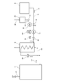
図1に示すボイラ装置において、11はボイラ、10はボイラ11からの蒸気送給路、12はボイラ11からの排ガス路である。排ガス路12には熱交換装置としてのエコノマイザ13が設けられており、ボイラ11からの燃焼排ガス14は、エコノマイザ13を通過したうえで系外に排出されるように構成されている。
In the boiler apparatus shown in FIG. 1 , 11 is a boiler, 10 is a steam supply line from the
15はボイラ11への給水を貯留する給水タンクで、ボイラ11への給水路16が接続されている。給水路16は、エコノマイザ13に連結されたうえでボイラ11へ接続されている。このため、給水タンク15からの給水17は、エコノマイザ13を通過したうえでボイラ11へ導かれるように構成されている。給水路16における給水タンク15とエコノマイザ13との間の部分には、上流側から順に、ストレーナ18と、給水ポンプ19と、逆止弁20とが設けられている。
A
図示は省略するが、蒸気送給路10には気水分装置が設けられており、この気水分離装置からの高圧高温水のためのドレン回収路24が、回収装置25へ導かれている。回収装置25には、回収したドレン水26を給水として再利用するために給水路16へ送るためのドレン供給路27が接続されている。このドレン供給路27は、給水路16における逆止弁20とエコノマイザ13との間の部分に連結されている。またドレン供給路27には、上流側から順に、回収装置25からのドレン水26を供給路16に送り込むためにこのドレン水26を加圧するためのブースタポンプ28と、流量調整弁29と、逆止弁30とが設けられている。
Although not shown, the
図1に示されるボイラ装置において、給水路16におけるエコノマイザ13とボイラ11との間の部分には、特にボイラ11の直前の部分には、給水流量安定化装置としてのオリフィス32が設けられている。このオリフィス32は、給水路16を通ってボイラ11へ送り込まれる給水17の流量調整すなわち流量制限を行うためのものである。
In the boiler apparatus shown in FIG. 1, an
このような構成において、ボイラ11を運転する際には、給水ポンプ19を間欠的に運転することによって、給水タンク15からの給水17を間欠的にボイラ11に供給する。ボイラ11では、図示を省略した燃焼装置がほぼ連続的に運転され、この燃焼装置の運転により発生した燃焼排ガス14が排ガス路12へ排出される。燃焼装置の運転により発生した蒸気は、蒸気送給路10を経て利用先へ供給される。
In such a configuration, when the
蒸気送給路10に設けられた気液分離装置からの高温水は、ドレン回収路24を経て回収装置25に回収される。そして回収装置25からの高温のドレン水26は、すなわち熱回収を行った状態のドレン水26は、必要に応じて、給水タンク15からの給水17と一緒に、給水17としてエコノマイザ13に供給される。そして、給水17は、エコノマイザ13を通過することによって、燃焼排ガス14との熱交換により熱回収し、そのうえでボイラ11に供給される。
The high-temperature water from the gas-liquid separation device provided in the
これによれば、燃焼排ガス14に含まれる熱エネルギと、気液分離装置から回収された高温のドレン水26に含まれる熱エネルギとを給水17により回収し、そのうえでこの給水17がボイラ11に供給される。その結果、ボイラ装置の高効率化、高蒸発量化を図ることができる。
According to this, the thermal energy contained in the
さらに、図示のボイラ装置においては、給水路16におけるエコノマイザ13とボイラ11との間の部分にオリフィス32が設けられているため、ボイラ11に送られる給水17の流量変動を低減させることができる。つまり、上述のように給水ポンプ19は間欠的に運転されるものであるが、この給水ポンプ19が運転を停止することで、エコノマイザ13の内部で給水17が流動せずに滞留している場合には、その滞留している給水17は、連続運転しているボイラ11からの燃焼排ガスによって常に熱を受けることになる。このため、エコノマイザ13の内部で給水が蒸発することがあり、この蒸発が起こると給水路16に気液混合流体が発生し、すなわち給水17と蒸発した蒸気とを含む流体となって、給水ポンプ19による圧送を行っただけでは流量が大きく変動することが避けられないが、本発明によれば、そのような場合であってもオリフィス32によって給水流量の安定化を図ることができる。これによって、ボイラ11の水位変動を緩和させることができ、それにもとづくボイラ装置のいっそうの高効率化、高蒸発量化を図ることができる。
Furthermore, in the illustrated boiler apparatus, since the
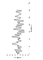
図2は、図1のボイラ装置からオリフィス32を取り除いたときのボイラ11の水位変動を例示する。横軸は給水している時間である。縦軸はボイラ11内の水位変動であり、水位は設定水位(400mm)をゼロとして表記し、変動値を設定水位から上下に目盛っている。図示のように大幅な水位変動が発生していることが理解される。
FIG. 2 illustrates water level fluctuations in
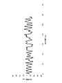
図3は、図1のボイラ装置すなわちオリフィス32を設けたものについての、ボイラ11の水位変動を例示するものである。図示のように、図2の場合に比べて水位の変動が効果的に抑制されていることを理解することができる。
FIG. 3 illustrates water level fluctuations in
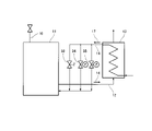
図4は、本発明の他の実施の形態のボイラ装置の要部の構成を示す。この図4の実施の形態においては、給水流量安定化装置として、図1の実施の形態のオリフィス32に代えて複数の弁を有するものが示されている。図示の例では、エコノマイザ13とボイラ11との間における給水路16の部分に、第1弁33と、第2弁34と、第3弁35とが並列にすなわち互いに分岐した状態で、設置されている。
FIG. 4 shows the configuration of the essential parts of a boiler apparatus according to another embodiment of the present invention. In the embodiment of FIG. 4, a water supply flow stabilizing device is shown having a plurality of valves instead of the
これらの弁33、34、35を制御する方法は、次の通りである。すなわち、ボイラ11が低燃焼の状態にあるときには、第1弁33を開く。このとき、第2弁34および第3弁35は閉じている。すると、第1弁33を通した少流量の給水17がボイラ11に供給され、ボイラの低燃焼状態に応じた適量の給水を行うことができる。ボイラ11が中燃焼の状態にあるときには、第1弁33と第2弁34とを開くとともに、第3弁35は閉じている状態を継続する。これによって、ボイラ11が低燃焼の状態にあるときに比べて多量の給水17をボイラに供給することができ、ボイラ11の中燃焼状態に応じた適量の給水を行うことができる。ボイラ11が高燃焼の状態にあるときには、すべての弁33、34、35を開く。すると、ボイラ11が中燃焼の状態にあるときに比べてさらに多量の給水17をボイラ11に供給することができ、ボイラ11の高燃焼状態に応じた適量の給水を行うことができる。しかも、給水17が弁33、34、35を通過するものであるため、そのときに圧損が生じて、オリフィス32を設けたときと同様に給水流量の安定化を図ることができる。しかも、上記のようにボイラ11の燃焼状態に応じた最適な流量でボイラ11に給水することができる。
The method of controlling these
なお、本発明によれば、上記したオリフィス32や弁33、34、35に代えて、給水流量を安定化させるための他の適宜の装置を設けることもできる。
According to the present invention, instead of the
すなわち、本発明のさらに他の実施の形態について、以下に説明する。図示は省略するが、この実施の形態では、エコノマイザからボイラまでの給水路にはオリフィスも弁も設置しない。それに代えて、給水ポンプを制御するための制御装置が設けられる。この制御装置は、給水ポンプを連続運転させるとともに、ボイラからの蒸発量や、蒸気の発生によるボイラの水位の変動を検知し、その検知信号にもとづいてPID制御などにより給水ポンプの運転状態を制御するものである。 That is, still another embodiment of the present invention will be described below. Although illustration is omitted, neither an orifice nor a valve is installed in the water supply passage from the economizer to the boiler in this embodiment. Alternatively, a controller is provided for controlling the water supply pump. This controller continuously operates the feedwater pump, detects the amount of evaporation from the boiler and changes in the water level of the boiler due to the generation of steam, and controls the operating state of the feedwater pump by PID control etc. based on the detection signal. It is something to do.
このような構成であると、制御装置によって給水ポンプを連続運転させるものであるため、連続的な給水が可能であり、このためエコノマイザにおいて給水が滞留することを原因とする蒸気の発生を防止することができて、ボイラへの給水量を安定化させることができ、しかも給水ポンプの運転状態を制御することで、燃焼状態に応じてボイラの水位を安定化させることもできる。 With such a configuration, since the water supply pump is operated continuously by the control device, continuous water supply is possible, and therefore the generation of steam caused by the water supply stagnation in the economizer is prevented. The amount of water supplied to the boiler can be stabilized, and by controlling the operating state of the water supply pump, the water level of the boiler can be stabilized according to the combustion state.
以上のように本発明によると、オリフィス32や、弁33、34、35や、図示を省略した制御装置などの給水流量安定化装置によって、ボイラ11への給水の安定化を図ることができ、このためボイラのいっそうの高効率化や高蒸発量化を図ることができる。
As described above, according to the present invention, the
11 ボイラ
13 エコノマイザ(熱交換装置)
14 燃焼排ガス
16 給水路
17 給水
19 給水ポンプ
26 ドレン水
32 オリフィス(給水流量安定化装置)
33 第1弁(給水流量安定化装置)
34 第2弁(給水流量安定化装置)
35 第3弁(給水流量安定化装置)
11
14
33 1st valve (water supply flow rate stabilizer)
34 Second valve (water supply flow rate stabilizer)
35 Third valve (water supply flow rate stabilizer)
Claims (5)
Priority Applications (1)
| Application Number | Priority Date | Filing Date | Title |
|---|---|---|---|
| JP2021071490A JP2022166344A (en) | 2021-04-21 | 2021-04-21 | Boiler device |
Applications Claiming Priority (1)
| Application Number | Priority Date | Filing Date | Title |
|---|---|---|---|
| JP2021071490A JP2022166344A (en) | 2021-04-21 | 2021-04-21 | Boiler device |
Publications (1)
| Publication Number | Publication Date |
|---|---|
| JP2022166344A true JP2022166344A (en) | 2022-11-02 |
Family
ID=83851645
Family Applications (1)
| Application Number | Title | Priority Date | Filing Date |
|---|---|---|---|
| JP2021071490A Pending JP2022166344A (en) | 2021-04-21 | 2021-04-21 | Boiler device |
Country Status (1)
| Country | Link |
|---|---|
| JP (1) | JP2022166344A (en) |
Citations (8)
| Publication number | Priority date | Publication date | Assignee | Title |
|---|---|---|---|---|
| JPH074209A (en) * | 1993-06-17 | 1995-01-10 | Toshiba Corp | Steam generator |
| JPH07260103A (en) * | 1994-03-23 | 1995-10-13 | Miura Co Ltd | High efficiency heat recovery system for waste heat recovery boiler |
| JPH08240301A (en) * | 1995-03-03 | 1996-09-17 | Toshiba Corp | Drum type boiler water supply control device |
| JP2008196833A (en) * | 2007-02-15 | 2008-08-28 | Mitsubishi Heavy Ind Ltd | Turbine equipment, exhaust heat recovering boiler apparatus and operation method for turbine equipment |
| JP2013148347A (en) * | 2013-03-11 | 2013-08-01 | Toshiba Corp | Water supply control device, and water supply control method |
| JP2014190639A (en) * | 2013-03-28 | 2014-10-06 | Samson Co Ltd | Feed water preheating boiler |
| JP2016183790A (en) * | 2015-03-25 | 2016-10-20 | 三浦工業株式会社 | Boiler device |
| JP2018194287A (en) * | 2017-05-16 | 2018-12-06 | 株式会社サムソン | Boiler for adjusting water supply amount |
-
2021
- 2021-04-21 JP JP2021071490A patent/JP2022166344A/en active Pending
Patent Citations (8)
| Publication number | Priority date | Publication date | Assignee | Title |
|---|---|---|---|---|
| JPH074209A (en) * | 1993-06-17 | 1995-01-10 | Toshiba Corp | Steam generator |
| JPH07260103A (en) * | 1994-03-23 | 1995-10-13 | Miura Co Ltd | High efficiency heat recovery system for waste heat recovery boiler |
| JPH08240301A (en) * | 1995-03-03 | 1996-09-17 | Toshiba Corp | Drum type boiler water supply control device |
| JP2008196833A (en) * | 2007-02-15 | 2008-08-28 | Mitsubishi Heavy Ind Ltd | Turbine equipment, exhaust heat recovering boiler apparatus and operation method for turbine equipment |
| JP2013148347A (en) * | 2013-03-11 | 2013-08-01 | Toshiba Corp | Water supply control device, and water supply control method |
| JP2014190639A (en) * | 2013-03-28 | 2014-10-06 | Samson Co Ltd | Feed water preheating boiler |
| JP2016183790A (en) * | 2015-03-25 | 2016-10-20 | 三浦工業株式会社 | Boiler device |
| JP2018194287A (en) * | 2017-05-16 | 2018-12-06 | 株式会社サムソン | Boiler for adjusting water supply amount |
Similar Documents
| Publication | Publication Date | Title |
|---|---|---|
| EP2703609B1 (en) | Steam turbine plant and control method of the same | |
| JP5008134B2 (en) | Water supply preheating boiler | |
| KR102332878B1 (en) | Oxy boiler power plant oxygen feed system heat integration | |
| JP2022166344A (en) | Boiler device | |
| JP4876114B2 (en) | Steam supply method and system for steamer | |
| JP4929010B2 (en) | Power generation system | |
| JP2008223701A (en) | Control device of process steam utilizing steam turbine | |
| JP4905941B2 (en) | Waste heat recovery boiler and its steam pressure control method | |
| KR20100054672A (en) | Waste heat recovery device for incinerator plant | |
| JP2622096B2 (en) | Combined refuse power plant with controllable feedwater temperature | |
| JPH11304102A (en) | Natural circulation system vertical gas flow exhaust gas boiler | |
| JP4266861B2 (en) | Boiler deaerator | |
| CN105626172B (en) | A kind of steam turbine generating equipment | |
| JP2013053823A (en) | Supply water preheating boiler | |
| JP2949287B2 (en) | Auxiliary steam extraction method for waste heat recovery boiler | |
| JP4127541B2 (en) | Power generation / desalination complex plant and operation method thereof | |
| JP2008223700A (en) | Control device of process steam utilizing steam turbine | |
| JPS60219404A (en) | Stabilizing device of deaerator output | |
| JP2008223702A (en) | Control device of process steam utilizing steam turbine | |
| JP2637194B2 (en) | Combined plant startup bypass system and its operation method | |
| JPH11344203A (en) | Method for recovering steam air heater drain | |
| JPH05240402A (en) | Method of operating waste heat recovery boiler | |
| JP6415219B2 (en) | Boiler, combined cycle plant and boiler operation method | |
| JP2000054808A (en) | Combined power generation system | |
| JP2015102258A (en) | Steam generation system |
Legal Events
| Date | Code | Title | Description |
|---|---|---|---|
| A621 | Written request for application examination |
Free format text: JAPANESE INTERMEDIATE CODE: A621 Effective date: 20240411 |
|
| A977 | Report on retrieval |
Free format text: JAPANESE INTERMEDIATE CODE: A971007 Effective date: 20241120 |
|
| A131 | Notification of reasons for refusal |
Free format text: JAPANESE INTERMEDIATE CODE: A131 Effective date: 20241210 |
|
| A521 | Request for written amendment filed |
Free format text: JAPANESE INTERMEDIATE CODE: A523 Effective date: 20250205 |
|
| A02 | Decision of refusal |
Free format text: JAPANESE INTERMEDIATE CODE: A02 Effective date: 20250513 |