JP2015102258A - Steam generation system - Google Patents
Steam generation system Download PDFInfo
- Publication number
- JP2015102258A JP2015102258A JP2013241650A JP2013241650A JP2015102258A JP 2015102258 A JP2015102258 A JP 2015102258A JP 2013241650 A JP2013241650 A JP 2013241650A JP 2013241650 A JP2013241650 A JP 2013241650A JP 2015102258 A JP2015102258 A JP 2015102258A
- Authority
- JP
- Japan
- Prior art keywords
- steam
- supply line
- pressure
- ejector
- suction
- Prior art date
- Legal status (The legal status is an assumption and is not a legal conclusion. Google has not performed a legal analysis and makes no representation as to the accuracy of the status listed.)
- Pending
Links
Images
Classifications
-
- Y—GENERAL TAGGING OF NEW TECHNOLOGICAL DEVELOPMENTS; GENERAL TAGGING OF CROSS-SECTIONAL TECHNOLOGIES SPANNING OVER SEVERAL SECTIONS OF THE IPC; TECHNICAL SUBJECTS COVERED BY FORMER USPC CROSS-REFERENCE ART COLLECTIONS [XRACs] AND DIGESTS
- Y02—TECHNOLOGIES OR APPLICATIONS FOR MITIGATION OR ADAPTATION AGAINST CLIMATE CHANGE
- Y02P—CLIMATE CHANGE MITIGATION TECHNOLOGIES IN THE PRODUCTION OR PROCESSING OF GOODS
- Y02P80/00—Climate change mitigation technologies for sector-wide applications
- Y02P80/10—Efficient use of energy, e.g. using compressed air or pressurized fluid as energy carrier
- Y02P80/15—On-site combined power, heat or cool generation or distribution, e.g. combined heat and power [CHP] supply
Abstract
Description
本発明は、低圧の蒸気を昇圧させる蒸気発生システムに関する。 The present invention relates to a steam generation system that pressurizes low-pressure steam.
工場などからは多くの排熱が発生する。排熱は、例えば、温水の形態で取り出される。排熱から得られる温水の温度は、高温の場合でも90℃程度である。 Much waste heat is generated from factories. The exhaust heat is extracted in the form of hot water, for example. The temperature of the hot water obtained from the exhaust heat is about 90 ° C. even when the temperature is high.
一般の工場における熱利用には、0.1〜1.0MPa(G)程度の中圧の蒸気が求められる。しかし、上記のような90℃程度の温水からは、低圧の蒸気しか製造することができず、排熱から得られる温水の用途は限定される。 For use of heat in a general factory, medium pressure steam of about 0.1 to 1.0 MPa (G) is required. However, only the low-pressure steam can be produced from the hot water of about 90 ° C. as described above, and the use of the hot water obtained from the exhaust heat is limited.
上記の問題を解決するために、特許文献1には、ヒートポンプとエゼクタとを備える蒸気発生システムが提案されている。前記蒸気発生システムにおいて、ヒートポンプは、排熱から得られる温水によって給水を加熱して低圧の蒸気を発生させる。一方、エゼクタは、前記低圧の蒸気を吸引蒸気として、また、ボイラなどから供給される高圧の蒸気を駆動蒸気として利用し、前記低圧の蒸気を工場で利用可能な中圧の蒸気に昇圧させる。このように、ヒートポンプとエゼクタとを用いることにより、排熱から得られる温水の用途を拡大することが可能である。 In order to solve the above problem, Patent Document 1 proposes a steam generation system including a heat pump and an ejector. In the steam generation system, the heat pump generates low-pressure steam by heating the feed water with hot water obtained from exhaust heat. On the other hand, the ejector uses the low-pressure steam as suction steam and the high-pressure steam supplied from a boiler or the like as driving steam, and boosts the low-pressure steam to medium-pressure steam that can be used in a factory. Thus, the use of hot water obtained from exhaust heat can be expanded by using a heat pump and an ejector.
しかしながら、エゼクタは、低圧の蒸気を昇圧させるために、駆動蒸気として多量の高圧の蒸気を必要とする。そのため、多量の高圧の蒸気を十分供給できない工場は、前記蒸気発生システムを設置することができなかった。 However, the ejector requires a large amount of high-pressure steam as driving steam in order to increase the pressure of low-pressure steam. Therefore, a factory that cannot sufficiently supply a large amount of high-pressure steam cannot install the steam generation system.
本発明は、比較的少量の高圧の蒸気によって低圧の蒸気を昇圧させる蒸気発生システムを提供することを目的とする。 An object of the present invention is to provide a steam generation system that pressurizes low-pressure steam with a relatively small amount of high-pressure steam.
本発明は、第1の蒸気を生成する第1蒸気発生部と、前記第1の蒸気よりも高圧の第2の蒸気を生成する第2蒸気発生部と、第1吸引蒸気流入口、第1駆動蒸気流入口及び第1吐出蒸気流出口を備える第1エゼクタであって、前記第1吸引蒸気流入口は、第1蒸気供給ラインを介して前記第1蒸気発生部に接続され、前記第1駆動蒸気流入口は、第2蒸気供給ラインを介して前記第2蒸気発生部に接続され、前記第1の蒸気を吸引蒸気として利用し且つ前記第2の蒸気を駆動蒸気として利用して、前記第1の蒸気よりも高圧で前記第2の蒸気よりも低圧の第3の蒸気を生成し、前記第3の蒸気を前記第1吐出蒸気流出口から流出させる第1エゼクタと、第2吸引蒸気流入口、第2駆動蒸気流入口及び第2吐出蒸気流出口を備える第2エゼクタであって、前記第2吸引蒸気流入口は、第3蒸気供給ラインを介して前記第1吐出蒸気流出口に接続され、前記第2駆動蒸気流入口は、前記第2蒸気供給ラインから分岐される第4蒸気供給ラインに接続され、前記第2吐出蒸気流出口は、第5蒸気供給ラインに接続され、前記第3蒸気供給ラインを流通する前記第3の蒸気を吸引蒸気として利用し且つ前記第4蒸気供給ラインを流通する前記第2の蒸気を駆動蒸気として利用して、前記第3の蒸気よりも高圧で前記第2の蒸気よりも低圧の第4の蒸気を生成し、前記第4の蒸気を前記第5蒸気供給ラインに流出させる第2エゼクタと、前記第3蒸気供給ラインから分岐され、前記第3の蒸気を流通させる第6蒸気供給ラインと、を備える蒸気発生システムに関する。 The present invention includes a first steam generating unit that generates first steam, a second steam generating unit that generates second steam having a pressure higher than that of the first steam, a first suction steam inlet, A first ejector having a driving steam inlet and a first discharge steam outlet, wherein the first suction steam inlet is connected to the first steam generator via a first steam supply line, and The driving steam inlet is connected to the second steam generating unit via a second steam supply line, uses the first steam as suction steam and uses the second steam as driving steam, A first ejector configured to generate a third steam having a pressure higher than that of the first steam and lower than that of the second steam, and causing the third steam to flow out from the first discharge steam outlet; and a second suction steam A second ejector having an inlet, a second drive steam inlet, and a second discharge steam outlet The second suction steam inlet is connected to the first discharge steam outlet via a third steam supply line, and the second driving steam inlet is branched from the second steam supply line. Connected to a fourth steam supply line, and the second discharge steam outlet is connected to a fifth steam supply line, uses the third steam flowing through the third steam supply line as suction steam, and Using the second steam flowing through the four steam supply lines as driving steam, generating a fourth steam having a pressure higher than that of the third steam and lower than that of the second steam; The present invention relates to a steam generation system comprising: a second ejector that causes steam to flow out to the fifth steam supply line; and a sixth steam supply line that branches from the third steam supply line and distributes the third steam.
また、前記蒸気発生システムは、温水を供給する温水供給部を更に備え、前記第1蒸気発生部は、前記温水供給部から供給される温水を利用して前記第1の蒸気を生成することが好ましい。 The steam generation system may further include a hot water supply unit that supplies hot water, and the first steam generation unit generates the first steam using the hot water supplied from the hot water supply unit. preferable.
本発明によれば、比較的少量の高圧の蒸気によって低圧の蒸気を昇圧させる蒸気発生システムを提供することができる。 ADVANTAGE OF THE INVENTION According to this invention, the steam generation system which pressurizes low pressure steam with a comparatively small amount of high pressure steam can be provided.
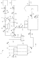
以下、本発明に係る蒸気発生システムの実施形態を、図面を参照しながら説明する。図1は、実施形態に係る蒸気発生システム1の全体構成図である。 Hereinafter, an embodiment of a steam generation system according to the present invention will be described with reference to the drawings. FIG. 1 is an overall configuration diagram of a steam generation system 1 according to an embodiment.
図1に示すように、実施形態に係る蒸気発生システム1は、第2蒸気発生部としての貫流ボイラ2と、蒸気ヘッダ3と、第1蒸気発生部としての蒸気発生装置4と、温水供給部としての温水タンク5と、第1エゼクタ6と、第2エゼクタ7と、第1蒸気圧力調整弁8と、第2蒸気圧力調整弁9と、吸引蒸気供給弁10と、第1駆動蒸気供給弁11と、第2駆動蒸気供給弁12と、制御部13、を備える。
As shown in FIG. 1, the steam generation system 1 according to the embodiment includes a once-through
更に、蒸気発生システム1は、第1蒸気供給ラインL1と、第2蒸気供給ラインL2と、第3蒸気供給ラインL3と、第4蒸気供給ラインL4と、第5蒸気供給ラインL5と、第6蒸気供給ラインL6と、温水供給ラインL7と、温水排出ラインL8と、給水ラインL9と、燃料供給ラインL10と、排温水供給ラインL11とを備える。本明細書における「ライン」とは、流路、径路、管路等の流体の流通が可能なラインの総称である。 Further, the steam generation system 1 includes a first steam supply line L1, a second steam supply line L2, a third steam supply line L3, a fourth steam supply line L4, a fifth steam supply line L5, and a sixth steam supply line L2. A steam supply line L6, a hot water supply line L7, a hot water discharge line L8, a water supply line L9, a fuel supply line L10, and an exhaust hot water supply line L11 are provided. The “line” in the present specification is a general term for lines capable of flowing a fluid such as a flow path, a radial path, and a pipeline.
なお、各ラインには、各種バルブ、各種センサ、逆止弁、オリフィス、ストレーナ等の機器が必要に応じて設けられるが、図1では適宜に図示を省略する。 Each line is provided with devices such as various valves, various sensors, check valves, orifices, strainers and the like as necessary, but the illustration is omitted as appropriate in FIG.
第1蒸気供給ラインL1の上流側の端部は、蒸気発生装置4の蒸気供給出口に接続される。第1蒸気供給ラインL1の下流側の端部は、第1エゼクタ6の第1吸引蒸気流入口61に接続される。第1蒸気供給ラインL1の途中には、吸引蒸気供給弁10が設けられている。蒸気発生装置4で生成された第1の蒸気W1は、第1蒸気供給ラインL1を流通し、吸引蒸気供給弁10を介して、第1エゼクタ6に向けて供給される。
The upstream end of the first steam supply line L <b> 1 is connected to the steam supply outlet of the
温水供給ラインL7の上流側の端部は、温水タンク5の流出口に接続される。温水供給ラインL7の下流側の端部は、蒸気発生装置4の温水入口に接続される。温水タンク5から流出する温水W7は、温水供給ラインL7を流通して、蒸気発生装置4に向けて供給される。
The upstream end of the hot water supply line L7 is connected to the outlet of the
温水排出ラインL8の上流側の端部は、蒸気発生装置4の温水出口に接続される。温水排出ラインL8の下流側の端部は、外部に連通する。蒸気発生装置4から排出される温水W7よりも低温の温水W8は、温水排出ラインL8を流通して、外部へ排出される。
The upstream end of the hot water discharge line L8 is connected to the hot water outlet of the
排温水供給ラインL11の上流側の端部は、工場などにおける温水供給元(図示せず)に接続される。排温水供給ラインL11の下流側の端部は、温水タンク5の流入口に接続される。負荷機器で発生する排ガスから熱を回収して得られる温水W7は、排温水供給ラインL11を介して、温水タンク5に供給される。
The upstream end of the exhaust hot water supply line L11 is connected to a hot water supply source (not shown) in a factory or the like. The downstream end of the exhaust hot water supply line L <b> 11 is connected to the inflow port of the
給水ラインL9の上流側の端部は、給水W9の給水供給元(図示せず)に接続される。給水ラインL9の下流側の端部は分岐し、一方の端部は貫流ボイラ2に接続され、他方の端部は蒸気発生装置4に接続される。給水供給元(図示せず)から供給される給水W9は、給水ラインL9を流通して、貫流ボイラ2及び蒸気発生装置4に供給される。
The upstream end of the water supply line L9 is connected to a water supply source (not shown) of the water supply W9. The downstream end of the water supply line L <b> 9 branches, one end is connected to the once-through
吸引蒸気供給弁10は、弁体の開度を調整して、第1エゼクタ6の第1吸引蒸気流入口61に供給される第1の蒸気W1の流量を調整可能にする。吸引蒸気供給弁10の開度は、制御部13により制御される。
The suction
蒸気発生装置4は、温水タンク5から供給される温水W7を利用して、第1の蒸気W1を生成する装置である。蒸気発生装置4は、熱交換器、圧力容器、蒸気供給口、温水入口及び温水出口を備える。給水供給元(図示せず)から供給される給水W9は、熱交換器を介して、温水タンク5から供給される温水W7と熱交換を行う。熱交換によって温められた給水W9は、次に、圧力容器に送られて、圧力容器内に噴霧され、さらに温水W7との熱交換を圧力容器内で行いながら蒸発する。これによって第1の蒸気W1が生成される。生成された第1の蒸気W1は、比較的低圧の蒸気である。蒸気発生装置4は、生成した第1の蒸気W1を、第1蒸気供給ラインL1に流通させ、吸引蒸気供給弁10を介して、第1エゼクタ6に供給する。
The
温水タンク5は、工場などの排熱から生成される温水W7を貯留し、蒸気発生装置4に温水W7を供給する設備である。温水タンク5と蒸気発生装置4との間は、温水供給ラインL7により接続される。
The
第2蒸気供給ラインL2の上流側の端部は、貫流ボイラ2に接続される。第2蒸気供給ラインL2の下流側の端部は、第1エゼクタ6の第1駆動蒸気流入口62に接続される。第2蒸気供給ラインL2の途中には、蒸気ヘッダ3が設けられる。また、第2蒸気供給ラインL2において、蒸気ヘッダ3と第1エゼクタ6との間には、第2蒸気供給ラインL2を第4蒸気供給ラインL4に分岐する分岐点J1が設けられる。分岐点J1と第1エゼクタ6との間には、第1駆動蒸気供給弁11が設けられる。
The upstream end of the second steam supply line L <b> 2 is connected to the once-through
第1駆動蒸気供給弁11は、弁体の開度を調整して、第1エゼクタ6の第1駆動蒸気流入口62に供給される第2の蒸気W2の流量を調整可能にする。第1駆動蒸気供給弁11の開度は、制御部13により制御される。
The first drive
貫流ボイラ2で生成された第2の蒸気W2は、第2蒸気供給ラインL2を流通し蒸気ヘッダ3を通過した後、分岐点J1において、第2蒸気供給ラインL2と第4蒸気供給ラインL4とに分岐して流通する。従って、第2の蒸気W2の一部は、第2蒸気供給ラインL2を流通し、第1駆動蒸気供給弁11を介して、第1エゼクタ6に供給される。また、第2の蒸気W2の残部は、第4蒸気供給ラインL4を流通して、第2エゼクタ7に供給される。
The second steam W2 generated in the once-through
第4蒸気供給ラインL4の上流側の端部は、第2蒸気供給ラインL2における分岐点J1に接続される。第4蒸気供給ラインL4の下流側の端部は、第2エゼクタ7の第2駆動蒸気流入口72に接続される。第4蒸気供給ラインL4の途中には、第2駆動蒸気供給弁12が設けられている。第2蒸気供給ラインL2における分岐点J1から供給される第2の蒸気W2の残部は、第4蒸気供給ラインL4を流通し、第2駆動蒸気供給弁12を介して、第2エゼクタ7に向けて供給される。
The upstream end of the fourth steam supply line L4 is connected to a branch point J1 in the second steam supply line L2. The downstream end of the fourth steam supply line L4 is connected to the second
第2駆動蒸気供給弁12は、弁体の開度を調整して、第2エゼクタ7の第2駆動蒸気流入口72に供給される第2の蒸気W2の流量を調整可能にする。第2駆動蒸気供給弁12の開度は、制御部13により制御される。
The second drive
第3蒸気供給ラインL3の上流側の端部は、第1エゼクタ6の第1吐出蒸気流出口63に接続される。第3蒸気供給ラインL3の下流側の端部は、第2エゼクタ7の第2吸引蒸気流入口71に接続される。そして、第3蒸気供給ラインL3の途中には、第3蒸気供給ラインL3を第6蒸気供給ラインL6に分岐する分岐点J2が設けられる。
The upstream end of the third steam supply line L3 is connected to the first
第1エゼクタ6から流出する第3の蒸気W3は、第3蒸気供給ラインL3に流通した後、分岐点J2において、第3蒸気供給ラインL3と第6蒸気供給ラインL6とに分岐して流通する。従って、第3の蒸気W3の一部は、第3蒸気供給ラインL3を流通して、第2エゼクタ7に向けて供給される。
The third steam W3 flowing out from the first ejector 6 flows to the third steam supply line L3, and then branches to the third steam supply line L3 and the sixth steam supply line L6 at the branch point J2. . Accordingly, a part of the third steam W3 is supplied to the
第6蒸気供給ラインL6の上流側の端部は、第3蒸気供給ラインL3における分岐点J2に接続される。第6蒸気供給ラインL6の下流側の端部は、第1の蒸気W1よりも高圧で第2の蒸気W2よりも低圧の蒸気で稼働する負荷機器Aに接続される。第6蒸気供給ラインL6において、分岐点J2と負荷機器Aとの間には、第1蒸気圧力調整弁8が設けられている。第3の蒸気W3の残部は、第6蒸気供給ラインL6を流通して、第1の蒸気W1よりも高圧で第2の蒸気W2よりも低圧の蒸気で稼働する負荷機器Aに供給される。 The upstream end of the sixth steam supply line L6 is connected to a branch point J2 in the third steam supply line L3. The downstream end of the sixth steam supply line L6 is connected to a load device A that operates with steam at a pressure higher than that of the first steam W1 and lower than that of the second steam W2. In the sixth steam supply line L6, a first steam pressure adjusting valve 8 is provided between the branch point J2 and the load device A. The remaining portion of the third steam W3 flows through the sixth steam supply line L6 and is supplied to the load device A that operates with steam higher in pressure than the first steam W1 and lower in pressure than the second steam W2.
第1蒸気圧力調整弁8は、弁体の開度を調整して、負荷機器Aに供給される第3の蒸気W3の圧力を所定圧に調整する。 The first steam pressure adjusting valve 8 adjusts the opening degree of the valve body to adjust the pressure of the third steam W3 supplied to the load device A to a predetermined pressure.
第5蒸気供給ラインL5の上流側の端部は、第2エゼクタ7の第2吐出蒸気流出口73に接続される。第5蒸気供給ラインL5の下流側の端部は、第3の蒸気W3よりも高圧で第2の蒸気W2よりも低圧の蒸気で稼働する負荷機器Bに接続される。第5蒸気供給ラインL5の途中には、第2蒸気圧力調整弁9が設けられる。
The upstream end of the fifth steam supply line L5 is connected to the second
第2蒸気圧力調整弁9は、弁体の開度を調整して、負荷機器Bに供給される第4の蒸気W4の圧力を所定圧に調整する。
The second steam
第2エゼクタ7から流出する第4の蒸気W4は、第5蒸気供給ラインL5を流通して、第2蒸気圧力調整弁9で圧力を所定圧に調整された後、第3の蒸気W3よりも高圧で第2の蒸気W2よりも低圧の蒸気で稼働する負荷機器Bに供給される。
The fourth steam W4 flowing out from the
貫流ボイラ2は、給水供給元(図示せず)から供給される給水W9を加熱して、比較的高圧の第2の蒸気W2を発生させる設備である。貫流ボイラ2は、缶体であるボイラ本体21を備える。
The once-through
ボイラ本体21は、下部管寄せ、水管、バーナ、上部管寄せ(いずれも図示せず)、を備える。
上部管寄せは、例えば環状に形成された中空の容器である。各水管の上端部は、上部管寄せと連通する。上部管寄せの上端には、第2蒸気供給ラインL2の上流側の端部が接続される。複数の水管で発生した第2の蒸気W2は、上部管寄せを介して第2蒸気供給ラインL2へ送出される。
The
The upper header is, for example, a hollow container formed in an annular shape. The upper end of each water pipe communicates with the upper header. The upstream end of the second steam supply line L2 is connected to the upper end of the upper header. The second steam W2 generated in the plurality of water pipes is sent to the second steam supply line L2 via the upper header.
バーナ部は、燃料G1(液体又は気体等)を燃焼させる燃焼装置である。バーナ部には、燃料供給ラインL10が接続される。燃料供給ラインL10は、燃料供給元(図示せず)から送出された燃料G1を、バーナ部に供給するラインである。 The burner unit is a combustion device that burns fuel G1 (liquid or gas, etc.). A fuel supply line L10 is connected to the burner portion. The fuel supply line L10 is a line that supplies the fuel G1 sent from a fuel supply source (not shown) to the burner unit.
蒸気ヘッダ3は、貫流ボイラ2から第2蒸気供給ラインL2を介して供給された第2の蒸気W2を一時的に溜めて、第2の蒸気W2を使用する第1エゼクタ6及び第2エゼクタ7へ供給する機器である。蒸気ヘッダ3は、第2蒸気供給ラインL2において、貫流ボイラ2と第1駆動蒸気供給弁11との間に設けられる。
The steam header 3 temporarily accumulates the second steam W2 supplied from the once-through
第1エゼクタ6は、第1の蒸気W1を吸引蒸気として利用し且つ第2の蒸気W2を駆動蒸気として利用して、第1の蒸気W1よりも高圧で第2の蒸気W2よりも低圧の第3の蒸気W3を生成する装置である。 The first ejector 6 uses the first steam W1 as suction steam and the second steam W2 as driving steam, and has a pressure higher than that of the first steam W1 and lower than that of the second steam W2. 3 is a device that generates three steam W3.
第1エゼクタ6は、第1吸引蒸気流入口61、第1駆動蒸気流入口62及び第1吐出蒸気流出口63を備える。第2蒸気供給ラインL2を流通した第2の蒸気W2は、第1エゼクタ6の第1駆動蒸気流入口62から、駆動蒸気として、第1エゼクタ6に流入する。
これにより、第1蒸気供給ラインL1を流通した第1の蒸気W1は、第1エゼクタ6の第1吸引蒸気流入口61において、吸引蒸気として、第1エゼクタ6に流入する。
The first ejector 6 includes a first
As a result, the first steam W1 flowing through the first steam supply line L1 flows into the first ejector 6 as suction steam at the first
第1エゼクタ6において、第1の蒸気W1と第2の蒸気W2とが混合することで第3の蒸気W3が生成される。生成された第3の蒸気W3は、第1エゼクタ6の第1吐出蒸気流出口63から流出して、第3蒸気供給ラインL3に流通する。
In the first ejector 6, the first steam W1 and the second steam W2 are mixed to generate a third steam W3. The generated third steam W3 flows out from the first
第2エゼクタ7は、第3の蒸気W3を吸引蒸気として利用し且つ第2の蒸気W2を駆動蒸気として利用して、第3の蒸気W3よりも高圧で第2の蒸気W2よりも低圧の第4の蒸気W4を生成する装置である。
The
第2エゼクタ7は、第2吸引蒸気流入口71、第2駆動蒸気流入口72及び第2吐出蒸気流出口73を備える。第4蒸気供給ラインL4を流通した第2の蒸気W2は、第2エゼクタ7の第2駆動蒸気流入口72から、駆動蒸気として、第2エゼクタ7に流入する。
これにより、第3蒸気供給ラインL3を流通した第3の蒸気W3の一部は、第2エゼクタ7の第2吸引蒸気流入口71において、吸引蒸気として、第2エゼクタ7に流入する。
The
As a result, a part of the third steam W3 flowing through the third steam supply line L3 flows into the
第2エゼクタ7において、第2の蒸気W2と第3の蒸気W3とが混合することで第4の蒸気W4が生成される。生成された第4の蒸気W4は、第2エゼクタ7の第2吐出蒸気流出口73から流出して、第5蒸気供給ラインL5に流通し第2蒸気圧力調整弁9を介して、負荷機器Bに供給される。
In the
制御部13は、吸引蒸気供給弁10と、第1駆動蒸気供給弁11と、第2駆動蒸気供給弁12と、に電気的に接続される。制御部13は、吸引蒸気供給弁10と、第1駆動蒸気供給弁11と、第2駆動蒸気供給弁12とに対して弁体の開閉(開度)に関する情報信号を送信する。
The
以上の構成による蒸気発生システム1は、以下の実施形態に示すように動作する。図1は、実施形態に係る蒸気発生システム1の全体構成図である。 The steam generation system 1 having the above configuration operates as shown in the following embodiment. FIG. 1 is an overall configuration diagram of a steam generation system 1 according to an embodiment.
まず、蒸気発生装置4において、給水供給元(図示せず)から供給される給水W9と、温水タンク5から供給される温水W7との間で、熱交換が行われる。熱交換によって温められた給水W9は、蒸気発生装置4内の圧力容器に送られ、圧力容器内に噴霧され、さらに温水W7との熱交換を圧力容器内で行いながら蒸発する。このとき、圧力容器において、比較的低圧である第1の蒸気W1が生成される。第1の蒸気W1は、第1蒸気供給ラインL1を流通し、吸引蒸気供給弁10で流量を調整された後、第1エゼクタ6の第1吸引蒸気流入口61に供給される。ここで、第1エゼクタ6に供給される第1の蒸気W1の圧力は、例えば、−0.02MPaで、その流量は150kg/hである。
First, in the
蒸気発生装置4において給水W9と熱交換を終えて熱を奪われた温水W8は、温水排出ラインL8を流通して、外部へ排出される。
The hot water W8, which has been deprived of heat after the heat exchange with the feed water W9 in the
一方、貫流ボイラ2は、燃料供給元(図示せず)から供給された燃料G1を使い、給水供給元(図示せず)から供給される給水W9加熱することで、第1の蒸気W1よりも高圧の第2の蒸気W2を生成する。第2の蒸気W2は、第2蒸気供給ラインL2を流通して蒸気ヘッダ3を通過した後、第2蒸気供給ラインL2に設けられた分岐点J1において、第2蒸気供給ラインL2と第4蒸気供給ラインL4とに分岐して流通する。
On the other hand, the once-through
第2蒸気供給ラインL2において、分岐点J1よりも下流側を流通する第2の蒸気W2は、第1駆動蒸気供給弁11で流量を調整された後、第1エゼクタ6の第1駆動蒸気流入口62に供給される。また、第4蒸気供給ラインL4を流通する第2の蒸気W2は、第2駆動蒸気供給弁12で流量を調整された後、第2エゼクタ7の第2駆動蒸気流入口72に供給される。
In the second steam supply line L2, the flow rate of the second steam W2 flowing downstream from the branch point J1 is adjusted by the first drive
ここで、第2蒸気供給ラインL2の分岐点J1よりも上流側を流通する第2の蒸気W2の圧力は、例えば、0.5MPaで、その流量は1320kg/hである。また、第1エゼクタ6の第1駆動蒸気流入口62に供給される第2の蒸気W2の圧力は、例えば、0.5MPaで、その流量は750kg/hである。更に、第2エゼクタ7の第2駆動蒸気流入口72に供給される第2の蒸気W2の圧力は、例えば、0.5MPaで、その流量は570kg/hである。
Here, the pressure of the second steam W2 flowing upstream from the branch point J1 of the second steam supply line L2 is, for example, 0.5 MPa, and the flow rate thereof is 1320 kg / h. The pressure of the second steam W2 supplied to the first
上記の動作により、圧力が0.5MPaである第2の蒸気W2は、駆動蒸気として、第1エゼクタ6の第1駆動蒸気流入口62から第1エゼクタ6に流入する。これにより、圧力が−0.02MPaである第1の蒸気W1は、吸引蒸気として、第1エゼクタ6の第1吸引蒸気流入口61から第1エゼクタ6に流入する。
Through the above operation, the second steam W2 having a pressure of 0.5 MPa flows as drive steam from the first
第1エゼクタ6では、第1の蒸気W1と第2の蒸気W2とが混合して、第1の蒸気W1よりも高圧で第2の蒸気W2よりも低圧の第3の蒸気W3が生成される。生成された第3の蒸気W3は、第1エゼクタ6の第1吐出蒸気流出口63から流出して、第3蒸気供給ラインL3に流通する。ここで、第3蒸気供給ラインL3を流通する第3の蒸気W3の圧力は、例えば、0.06MPaで、その流量は900kg/hである。
In the first ejector 6, the first steam W1 and the second steam W2 are mixed to generate a third steam W3 that is higher in pressure than the first steam W1 and lower in pressure than the second steam W2. . The generated third steam W3 flows out from the first
従って、第1エゼクタ6は、第1の蒸気W1よりも高圧の第2の蒸気W2を利用して、第2の蒸気W2よりも低圧の第1の蒸気W1を昇圧させて、第1の蒸気W1よりも高圧で第2の蒸気W2よりも低圧の第3の蒸気W3として流出させる。 Accordingly, the first ejector 6 uses the second steam W2 having a pressure higher than that of the first steam W1 to increase the pressure of the first steam W1 having a pressure lower than that of the second steam W2, so that the first steam A third steam W3 having a pressure higher than W1 and a pressure lower than that of the second steam W2 is caused to flow out.
次に、第3の蒸気W3は、第3蒸気供給ラインL3の途中に設けられた分岐点J2において、第3蒸気供給ラインL3と第6蒸気供給ラインL6とに分岐して流通する。 Next, the third steam W3 branches and flows into the third steam supply line L3 and the sixth steam supply line L6 at a branch point J2 provided in the middle of the third steam supply line L3.
第3蒸気供給ラインL3において分岐点J2よりも下流側を流通する第3の蒸気W3は、第2エゼクタ7の第2吸引蒸気流入口71に供給される。また、第6蒸気供給ラインL6を流通する第3の蒸気W3は、第1蒸気圧力調整弁8で圧力を所定圧に調整された後、第1の蒸気W1よりも高圧で第2の蒸気W2よりも低圧の蒸気で稼働する負荷機器Aに供給される。
The third steam W3 flowing downstream from the branch point J2 in the third steam supply line L3 is supplied to the second
ここで、第2エゼクタ7の第2吸引蒸気流入口71に供給される第3の蒸気W3の圧力は、例えば、0.06MPaで、その流量は150kg/hである。また、第1の蒸気W1よりも高圧で第2の蒸気W2よりも低圧の蒸気で稼働する負荷機器Aに供給される第3の蒸気W3の圧力は、例えば、0.06MPaで、その流量は750kg/hである。
Here, the pressure of the third steam W3 supplied to the second
上記の動作により、圧力が0.5MPaである第2の蒸気W2は、駆動蒸気として、第2エゼクタ7の第2駆動蒸気流入口72から第2エゼクタ7に流入する。これにより、圧力が0.06MPaである第3の蒸気W3は、吸引蒸気として、第2エゼクタ7の第2吸引蒸気流入口71から第2エゼクタ7に流入する。
Through the above operation, the second steam W2 having a pressure of 0.5 MPa flows as drive steam from the second
第2エゼクタ7では、第2の蒸気W2と第3の蒸気W3とが混合して、第3の蒸気W3よりも高圧で第2の蒸気W2よりも低圧の第4の蒸気W4が生成される。生成された第4の蒸気W4は、第2エゼクタ7の第2吐出蒸気流出口73から流出して、第5蒸気供給ラインL5に流通する。ここで、第5蒸気供給ラインL5を流通する第4の蒸気W4の圧力は、例えば、0.2MPaで、その流量は720kg/hである。
In the
従って、第2エゼクタ7は、第3の蒸気W3よりも高圧の第2の蒸気W2を利用して、第2の蒸気W2よりも低圧の第3の蒸気W3を昇圧させて、第3の蒸気W3よりも高圧で第2の蒸気W2よりも低圧の第4の蒸気W4として流出させる。
Therefore, the
第4の蒸気W4は、第5蒸気供給ラインL5を流通し、第5蒸気供給ラインL5の途中に設けられた第2蒸気圧力調整弁9で圧力を所定圧に調整された後、比較的高圧の蒸気で稼働する負荷機器Bに供給される。
The fourth steam W4 flows through the fifth steam supply line L5, and after the pressure is adjusted to a predetermined pressure by the second steam
以上のような構成を有する本実施形態に係る蒸気発生システム1によれば、以下の効果を奏する。
本実施形態における蒸気発生システム1は、第1の蒸気W1を生成する蒸気発生装置4と、第1の蒸気W1よりも高圧の第2の蒸気W2を生成する貫流ボイラ2と、第1吸引蒸気流入口61、第1駆動蒸気流入口62及び第1吐出蒸気流出口63を備える第1エゼクタ6であって、第1吸引蒸気流入口61は、第1蒸気供給ラインL1を介して蒸気発生装置4に接続され、第1駆動蒸気流入口62は、第2蒸気供給ラインL2を介して貫流ボイラ2に接続され、第1の蒸気W1を吸引蒸気として利用し且つ第2の蒸気W2を駆動蒸気として利用して、第1の蒸気W1よりも高圧で第2の蒸気W2よりも低圧の第3の蒸気W3を生成し、第3の蒸気W3を第1吐出蒸気流出口63から流出させる第1エゼクタ6と、第2吸引蒸気流入口71、第2駆動蒸気流入口72及び第2吐出蒸気流出口73を備える第2エゼクタ7であって、第2吸引蒸気流入口71は、第3蒸気供給ラインL3を介して第1吐出蒸気流出口63に接続され、第2駆動蒸気流入口72は、第2蒸気供給ラインL2から分岐される第4蒸気供給ラインL4に接続され、第2吐出蒸気流出口73は、第5蒸気供給ラインL5に接続され、第3蒸気供給ラインL3を流通する第3の蒸気W3を吸引蒸気として利用し且つ第4蒸気供給ラインL4を流通する第2の蒸気W2を駆動蒸気として利用して、第3の蒸気W3よりも高圧で第2の蒸気W2よりも低圧の第4の蒸気W4を生成し、第4の蒸気W4を第5蒸気供給ラインL5に流出させる第2エゼクタ7と、第3蒸気供給ラインL3から分岐され、第3の蒸気W3を流通させる第6蒸気供給ラインL6と、を備える。
The steam generation system 1 according to the present embodiment having the above-described configuration has the following effects.
The steam generation system 1 in the present embodiment includes a
このため、第6蒸気供給ラインL6を流通する第3の蒸気W3は、その分岐点J2から下流側で、第3蒸気供給ラインL3と第6蒸気供給ラインL6とに分岐して流通する。これにより、第2エゼクタ7へ供給される第3の蒸気W3の流量が減少する。一般的に、エゼクタを用いて気体を昇圧させる場合、吸引される気体の流量の約5〜6倍の駆動蒸気が必要となる。従って、蒸気発生システム1は、第1エゼクタ6で昇圧させた第3の蒸気W3の一部を第2エゼクタ7に吸引蒸気として供給することにより、第2エゼクタ7の昇圧に必要とされる駆動蒸気の流量を削減することが可能となる。つまり、比較的少量の高圧の蒸気によって低圧の蒸気を昇圧させることができる。
For this reason, the third steam W3 flowing through the sixth steam supply line L6 is branched from the branch point J2 to the third steam supply line L3 and the sixth steam supply line L6. Thereby, the flow volume of the 3rd vapor | steam W3 supplied to the
また、蒸気発生システム1は、第1エゼクタ6で昇圧させた第3の蒸気W3の一部のみを第2エゼクタ7で利用するため、第2エゼクタ7における必要以上の第4の蒸気W4の生成を抑えることができる。
更に、蒸気発生システム1は、第3蒸気供給ラインL3から分岐した第6蒸気供給ラインL6を流通する第3の蒸気W3を、第1の蒸気W1よりも高圧で第2の蒸気W2よりも低圧の蒸気で稼働する負荷機器Aに利用することができる。
In addition, since the steam generation system 1 uses only the part of the third steam W3 boosted by the first ejector 6 in the
Furthermore, the steam generation system 1 causes the third steam W3 flowing through the sixth steam supply line L6 branched from the third steam supply line L3 to be higher in pressure than the first steam W1 and lower in pressure than the second steam W2. It can be used for the load equipment A that operates on the steam.
また、本実施形態における蒸気発生システム1は、温水を供給する温水タンク5を更に備え、蒸気発生装置4は、温水タンク5から供給される温水W7を利用して第1の蒸気W1を生成する。
Moreover, the steam generation system 1 in the present embodiment further includes a
このため、蒸気発生システム1は、工場などの排熱から生成される温水W7を有効に利用して、工場で再び利用可能な中圧の第4の蒸気W4を生成することができる。 For this reason, the steam generation system 1 can produce | generate the 4th steam W4 of the medium pressure which can be utilized again in a factory effectively using the warm water W7 produced | generated from exhaust heat, such as a factory.
以上、本発明の蒸気発生システム1の好ましい実施形態について説明したが、本発明は、上述した実施形態に制限されるものではなく、適宜変更が可能である。
例えば、蒸気発生システム1は、第1エゼクタ6と第2エゼクタ7とを備え、中圧の第4の蒸気W4を生成する。しかし、これに限定されず、蒸気発生システムは、例えば、3つ以上のエゼクタを備え、更に中圧の蒸気を生成するよう構成されてもよい。
As mentioned above, although preferable embodiment of the steam generation system 1 of this invention was described, this invention is not restrict | limited to embodiment mentioned above, It can change suitably.
For example, the steam generation system 1 includes a first ejector 6 and a
また、蒸気発生システム1は、蒸気発生装置4を備え、比較的低圧の第1の蒸気を生成していた。しかし、これに限定されず、蒸気発生システムは、フラッシュタンク、吸収式ヒートポンプ、その他低圧の蒸気を発生させる設備を備えていてもよい。
In addition, the steam generation system 1 includes the
また、蒸気発生システム1は、第2蒸気発生部として、貫流ボイラ2を備え、給水供給元(図示せず)から供給される給水W9を加熱して、比較的高圧の第2の蒸気W2を発生させていた。しかし、これに限定されず、第2蒸気発生部は、ヒートポンプ、その他比較的高圧の蒸気を発生させる機器であってもよい。
In addition, the steam generation system 1 includes a once-through
1 蒸気発生システム
2 貫流ボイラ(第2蒸気発生部)
4 蒸気発生装置(第1蒸気発生部)
6 第1エゼクタ
7 第2エゼクタ
61 第1吸引蒸気流入口
62 第1駆動蒸気流入口
63 第1吐出蒸気流出口
71 第2吸引蒸気流入口
72 第2駆動蒸気流入口
73 第2吐出蒸気流出口
L1 第1蒸気供給ライン
L2 第2蒸気供給ライン
L3 第3蒸気供給ライン
L4 第4蒸気供給ライン
L5 第5蒸気供給ライン
L6 第6蒸気供給ライン
W1 第1の蒸気
W2 第2の蒸気
W3 第3の蒸気
W4 第4の蒸気
1
4 Steam generator (first steam generator)
6
Claims (2)
前記第1の蒸気よりも高圧の第2の蒸気を生成する第2蒸気発生部と、
第1吸引蒸気流入口、第1駆動蒸気流入口及び第1吐出蒸気流出口を備える第1エゼクタであって、前記第1吸引蒸気流入口は、第1蒸気供給ラインを介して前記第1蒸気発生部に接続され、前記第1駆動蒸気流入口は、第2蒸気供給ラインを介して前記第2蒸気発生部に接続され、前記第1の蒸気を吸引蒸気として利用し且つ前記第2の蒸気を駆動蒸気として利用して、前記第1の蒸気よりも高圧で前記第2の蒸気よりも低圧の第3の蒸気を生成し、前記第3の蒸気を前記第1吐出蒸気流出口から流出させる第1エゼクタと、
第2吸引蒸気流入口、第2駆動蒸気流入口及び第2吐出蒸気流出口を備える第2エゼクタであって、前記第2吸引蒸気流入口は、第3蒸気供給ラインを介して前記第1吐出蒸気流出口に接続され、前記第2駆動蒸気流入口は、前記第2蒸気供給ラインから分岐される第4蒸気供給ラインに接続され、前記第2吐出蒸気流出口は、第5蒸気供給ラインに接続され、前記第3蒸気供給ラインを流通する前記第3の蒸気を吸引蒸気として利用し且つ前記第4蒸気供給ラインを流通する前記第2の蒸気を駆動蒸気として利用して、前記第3の蒸気よりも高圧で前記第2の蒸気よりも低圧の第4の蒸気を生成し、前記第4の蒸気を前記第5蒸気供給ラインに流出させる第2エゼクタと、
前記第3蒸気供給ラインから分岐され、前記第3の蒸気を流通させる第6蒸気供給ラインと、を備える蒸気発生システム。 A first steam generating section for generating first steam;
A second steam generating section for generating second steam having a pressure higher than that of the first steam;
A first ejector comprising a first suction steam inlet, a first drive steam inlet, and a first discharge steam outlet, wherein the first suction steam inlet is connected to the first steam via a first steam supply line. Connected to the generator, the first drive steam inlet is connected to the second steam generator via a second steam supply line, and uses the first steam as suction steam and the second steam. Is used as driving steam to generate third steam that is higher in pressure than the first steam and lower in pressure than the second steam, and causes the third steam to flow out from the first discharge steam outlet. The first ejector;
A second ejector comprising a second suction steam inlet, a second drive steam inlet, and a second discharge steam outlet, wherein the second suction steam inlet is connected to the first discharge via a third steam supply line. Connected to a steam outlet, the second drive steam inlet is connected to a fourth steam supply line branched from the second steam supply line, and the second discharge steam outlet is connected to a fifth steam supply line. The third steam connected and using the third steam flowing through the third steam supply line as suction steam and using the second steam flowing through the fourth steam supply line as driving steam, the third steam A second ejector for generating a fourth steam at a pressure higher than the steam and lower than the second steam, and causing the fourth steam to flow into the fifth steam supply line;
A steam generation system comprising: a sixth steam supply line that branches from the third steam supply line and distributes the third steam.
前記第1蒸気発生部は、前記温水供給部から供給される温水を利用して前記第1の蒸気を生成する請求項1に記載の蒸気発生システム。 It further comprises a hot water supply part for supplying hot water,
The steam generation system according to claim 1, wherein the first steam generation unit generates the first steam using hot water supplied from the hot water supply unit.
Priority Applications (1)
| Application Number | Priority Date | Filing Date | Title |
|---|---|---|---|
| JP2013241650A JP2015102258A (en) | 2013-11-22 | 2013-11-22 | Steam generation system |
Applications Claiming Priority (1)
| Application Number | Priority Date | Filing Date | Title |
|---|---|---|---|
| JP2013241650A JP2015102258A (en) | 2013-11-22 | 2013-11-22 | Steam generation system |
Publications (1)
| Publication Number | Publication Date |
|---|---|
| JP2015102258A true JP2015102258A (en) | 2015-06-04 |
Family
ID=53378099
Family Applications (1)
| Application Number | Title | Priority Date | Filing Date |
|---|---|---|---|
| JP2013241650A Pending JP2015102258A (en) | 2013-11-22 | 2013-11-22 | Steam generation system |
Country Status (1)
| Country | Link |
|---|---|
| JP (1) | JP2015102258A (en) |
Cited By (1)
| Publication number | Priority date | Publication date | Assignee | Title |
|---|---|---|---|---|
| JP2020046142A (en) * | 2018-09-20 | 2020-03-26 | 三浦工業株式会社 | Steam supply system |
-
2013
- 2013-11-22 JP JP2013241650A patent/JP2015102258A/en active Pending
Cited By (2)
| Publication number | Priority date | Publication date | Assignee | Title |
|---|---|---|---|---|
| JP2020046142A (en) * | 2018-09-20 | 2020-03-26 | 三浦工業株式会社 | Steam supply system |
| JP7095521B2 (en) | 2018-09-20 | 2022-07-05 | 三浦工業株式会社 | Steam supply system |
Similar Documents
| Publication | Publication Date | Title |
|---|---|---|
| JP5008485B2 (en) | Steam power plant for regenerating superheated steam and power generation equipment equipped with this steam power plant | |
| TWI646286B (en) | Thermally integrated coal-fired oxygen plant | |
| KR102332878B1 (en) | Oxy boiler power plant oxygen feed system heat integration | |
| RU2014127721A (en) | POWER PLANT WITH BUILT-IN PRELIMINARY HEATING OF FUEL GAS | |
| JP2012007762A (en) | Drain recovery facility | |
| JP2011179494A (en) | Systems and methods for prewarming heat recovery steam generator piping | |
| JP2012102711A (en) | Temperature reducing device steam heat recovery facilities | |
| JP2015102258A (en) | Steam generation system | |
| MX2018014295A (en) | Condensate recirculation. | |
| JP6516993B2 (en) | Combined cycle plant and boiler steam cooling method | |
| JP2009168320A (en) | Heat pump type hot water supply system | |
| JP2008248808A (en) | Power generation system | |
| SI2801723T1 (en) | Solar energy and external source steam complementary power generation apparatus | |
| JP2016070526A5 (en) | Combined cycle plant and boiler steam cooling method | |
| JP2010096422A (en) | Boiler unit and power generation system | |
| CN105488324A (en) | Type selection method and system for safety valve of feed water heater in nuclear plant | |
| JP2008223701A (en) | Control device of process steam utilizing steam turbine | |
| JP2015087043A (en) | Boiler system | |
| JPH0544405A (en) | Steam turbine plant | |
| CN208934759U (en) | A kind of high steam decompression cooling noise reduction system | |
| KR101334687B1 (en) | Main steam feeding device for generating system | |
| KR101604219B1 (en) | Method for controlling a thermal power plant using regulator valves | |
| CN108072030A (en) | For the heat regenerative system of high parameter double reheat power generation sets | |
| JP2017160878A (en) | Injector type pressure increasing device and rankine cycle system | |
| CN108626715A (en) | Heat regenerative system equipped with multistage deaerator |