JP2022035362A5 - - Google Patents
Download PDFInfo
- Publication number
- JP2022035362A5 JP2022035362A5 JP2020139615A JP2020139615A JP2022035362A5 JP 2022035362 A5 JP2022035362 A5 JP 2022035362A5 JP 2020139615 A JP2020139615 A JP 2020139615A JP 2020139615 A JP2020139615 A JP 2020139615A JP 2022035362 A5 JP2022035362 A5 JP 2022035362A5
- Authority
- JP
- Japan
- Prior art keywords
- contacts
- face
- contact portion
- rotation direction
- direction side
- Prior art date
- Legal status (The legal status is an assumption and is not a legal conclusion. Google has not performed a legal analysis and makes no representation as to the accuracy of the status listed.)
- Granted
Links
- 230000007935 neutral effect Effects 0.000 description 2
- 230000002093 peripheral effect Effects 0.000 description 1
Images
Description
4つのストッパ用突起42bは、フランジ42の外周面から径方向外方に突出して形成されている。各ストッパ用突起42bが形成された位置は、各収容部401,402の円周方向の中央部の径方向外方である。そして、入力側プレート30とハブフランジ40とが互いに相対回転した際に、ストッパ用突起42bが第1プレート31のストッパ部31aに当接することにより、入力側プレート30とハブフランジ40との相対回転が禁止される。
The four stopper protrusions 42 b are formed to protrude radially outward from the outer peripheral surface of the flange 42 . The positions where the stopper projections 42b are formed are radially outward of the center portions of the housing portions 401 and 402 in the circumferential direction. When the input side plate 30 and the hub flange 40 rotate relative to each other, the stopper projection 42b abuts against the stopper portion 31a of the first plate 31 , thereby causing relative rotation between the input side plate 30 and the hub flange 40. is prohibited.
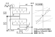
図15は、捩り角度1°から中立状態に移行した状態を示している。ここでは、入力側プレートIPは摩擦部材FPとともに、中立状態に戻り、この間は、ヒステリシストルクは発生しない。
FIG. 15 shows a state in which a torsion angle of 1° is shifted to a neutral state. Here, the input side plate IP returns to the neutral state together with the friction member FP, and no hysteresis torque is generated during this period.
Claims (1)
請求項1から3のいずれかに記載のダンパ装置。
The friction member includes a first contact portion that contacts an end face of the first elastic member on the first rotation direction side, and a second contact portion that contacts an end face of the second elastic member on the second rotation direction side. has a part and
The damper device according to any one of claims 1 to 3.
Priority Applications (4)
| Application Number | Priority Date | Filing Date | Title |
|---|---|---|---|
| JP2020139615A JP7473419B2 (en) | 2020-08-20 | 2020-08-20 | Damper Device |
| CN202110821222.XA CN114076174A (en) | 2020-08-20 | 2021-07-20 | Vibration damping device |
| US17/380,274 US11965576B2 (en) | 2020-08-20 | 2021-07-20 | Damper device |
| DE102021118810.5A DE102021118810A1 (en) | 2020-08-20 | 2021-07-21 | damping device |
Applications Claiming Priority (1)
| Application Number | Priority Date | Filing Date | Title |
|---|---|---|---|
| JP2020139615A JP7473419B2 (en) | 2020-08-20 | 2020-08-20 | Damper Device |
Publications (3)
| Publication Number | Publication Date |
|---|---|
| JP2022035362A JP2022035362A (en) | 2022-03-04 |
| JP2022035362A5 true JP2022035362A5 (en) | 2023-08-04 |
| JP7473419B2 JP7473419B2 (en) | 2024-04-23 |
Family
ID=80112901
Family Applications (1)
| Application Number | Title | Priority Date | Filing Date |
|---|---|---|---|
| JP2020139615A Active JP7473419B2 (en) | 2020-08-20 | 2020-08-20 | Damper Device |
Country Status (4)
| Country | Link |
|---|---|
| US (1) | US11965576B2 (en) |
| JP (1) | JP7473419B2 (en) |
| CN (1) | CN114076174A (en) |
| DE (1) | DE102021118810A1 (en) |
Family Cites Families (9)
| Publication number | Priority date | Publication date | Assignee | Title |
|---|---|---|---|---|
| BR8502761A (en) * | 1984-06-12 | 1986-02-18 | Luk Lamellen & Kupplungsbau | SET FOR ROTATION SHOCK COMPENSATION |
| DE8525579U1 (en) * | 1985-09-07 | 1993-06-03 | Luk Lamellen Und Kupplungsbau Gmbh, 7580 Buehl, De | |
| JP2002340095A (en) | 2001-05-15 | 2002-11-27 | Exedy Corp | Damper mechanism |
| JP2005207551A (en) * | 2003-06-06 | 2005-08-04 | Exedy Corp | Frictional resistance generating mechanism |
| JP2010203558A (en) | 2009-03-04 | 2010-09-16 | Toyota Motor Corp | Clutch disc for vehicle |
| JP6141783B2 (en) | 2014-03-14 | 2017-06-07 | 株式会社エクセディ | Damper disk assembly |
| JP6616662B2 (en) | 2015-10-30 | 2019-12-04 | 株式会社エクセディ | Damper device |
| JP2017125579A (en) | 2016-01-14 | 2017-07-20 | トヨタ自動車株式会社 | Damper device for vehicle |
| JP7473420B2 (en) * | 2020-08-20 | 2024-04-23 | 株式会社エクセディ | Damper Device |
-
2020
- 2020-08-20 JP JP2020139615A patent/JP7473419B2/en active Active
-
2021
- 2021-07-20 US US17/380,274 patent/US11965576B2/en active Active
- 2021-07-20 CN CN202110821222.XA patent/CN114076174A/en active Pending
- 2021-07-21 DE DE102021118810.5A patent/DE102021118810A1/en active Pending
Similar Documents
| Publication | Publication Date | Title |
|---|---|---|
| JP2018132160A5 (en) | ||
| JP6541983B2 (en) | Damper disc assembly | |
| JP2022035363A5 (en) | ||
| JP2022035362A5 (en) | ||
| JP6471486B2 (en) | Damper device | |
| JPS598693B2 (en) | Torsion damper device especially for automobile clutches | |
| WO2016129183A1 (en) | Damper disk assembly | |
| TWI752803B (en) | Hinge | |
| JP2599880Y2 (en) | Viscous torsional vibration damping device | |
| JP7429130B2 (en) | Spring seat and damper device | |
| JPH10238589A (en) | Frictional resistance generation mechanism | |
| JP2022030693A5 (en) | ||
| JP6976413B2 (en) | Clutch device | |
| EP2963311A2 (en) | Damper device | |
| JP2021134835A5 (en) | ||
| JP2022052126A5 (en) | ||
| JP7422617B2 (en) | Damper device with torque limiter | |
| JP2016008712A (en) | Damper device | |
| JPS58187623A (en) | Clutch disc | |
| JP7375213B2 (en) | damper device | |
| JP6956047B2 (en) | Damper device | |
| JP7422618B2 (en) | damper device | |
| JP2607327Y2 (en) | Clutch disc assembly | |
| JP3843463B2 (en) | Torsional vibration damper | |
| JP2016148359A (en) | Damper disc assembly |