JP7429130B2 - Spring seat and damper device - Google Patents
Spring seat and damper device Download PDFInfo
- Publication number
- JP7429130B2 JP7429130B2 JP2020030441A JP2020030441A JP7429130B2 JP 7429130 B2 JP7429130 B2 JP 7429130B2 JP 2020030441 A JP2020030441 A JP 2020030441A JP 2020030441 A JP2020030441 A JP 2020030441A JP 7429130 B2 JP7429130 B2 JP 7429130B2
- Authority
- JP
- Japan
- Prior art keywords
- rotating body
- plate
- damper device
- circumferential direction
- spring seat
- Prior art date
- Legal status (The legal status is an assumption and is not a legal conclusion. Google has not performed a legal analysis and makes no representation as to the accuracy of the status listed.)
- Active
Links
- 230000002093 peripheral effect Effects 0.000 claims description 21
- 230000000149 penetrating effect Effects 0.000 claims description 4
- 239000011347 resin Substances 0.000 description 15
- 229920005989 resin Polymers 0.000 description 15
- 238000013016 damping Methods 0.000 description 3
- 230000005540 biological transmission Effects 0.000 description 2
- 230000007935 neutral effect Effects 0.000 description 2
- 238000010586 diagram Methods 0.000 description 1
- 230000004048 modification Effects 0.000 description 1
- 238000012986 modification Methods 0.000 description 1
- 230000001105 regulatory effect Effects 0.000 description 1
Images

Classifications
-
- F—MECHANICAL ENGINEERING; LIGHTING; HEATING; WEAPONS; BLASTING
- F16—ENGINEERING ELEMENTS AND UNITS; GENERAL MEASURES FOR PRODUCING AND MAINTAINING EFFECTIVE FUNCTIONING OF MACHINES OR INSTALLATIONS; THERMAL INSULATION IN GENERAL
- F16F—SPRINGS; SHOCK-ABSORBERS; MEANS FOR DAMPING VIBRATION
- F16F15/00—Suppression of vibrations in systems; Means or arrangements for avoiding or reducing out-of-balance forces, e.g. due to motion
- F16F15/10—Suppression of vibrations in rotating systems by making use of members moving with the system
- F16F15/12—Suppression of vibrations in rotating systems by making use of members moving with the system using elastic members or friction-damping members, e.g. between a rotating shaft and a gyratory mass mounted thereon
- F16F15/131—Suppression of vibrations in rotating systems by making use of members moving with the system using elastic members or friction-damping members, e.g. between a rotating shaft and a gyratory mass mounted thereon the rotating system comprising two or more gyratory masses
- F16F15/133—Suppression of vibrations in rotating systems by making use of members moving with the system using elastic members or friction-damping members, e.g. between a rotating shaft and a gyratory mass mounted thereon the rotating system comprising two or more gyratory masses using springs as elastic members, e.g. metallic springs
- F16F15/137—Suppression of vibrations in rotating systems by making use of members moving with the system using elastic members or friction-damping members, e.g. between a rotating shaft and a gyratory mass mounted thereon the rotating system comprising two or more gyratory masses using springs as elastic members, e.g. metallic springs the elastic members consisting of two or more springs of different kinds, e.g. elastomeric members and wound springs
-
- F—MECHANICAL ENGINEERING; LIGHTING; HEATING; WEAPONS; BLASTING
- F16—ENGINEERING ELEMENTS AND UNITS; GENERAL MEASURES FOR PRODUCING AND MAINTAINING EFFECTIVE FUNCTIONING OF MACHINES OR INSTALLATIONS; THERMAL INSULATION IN GENERAL
- F16D—COUPLINGS FOR TRANSMITTING ROTATION; CLUTCHES; BRAKES
- F16D3/00—Yielding couplings, i.e. with means permitting movement between the connected parts during the drive
- F16D3/02—Yielding couplings, i.e. with means permitting movement between the connected parts during the drive adapted to specific functions
- F16D3/12—Yielding couplings, i.e. with means permitting movement between the connected parts during the drive adapted to specific functions specially adapted for accumulation of energy to absorb shocks or vibration
-
- F—MECHANICAL ENGINEERING; LIGHTING; HEATING; WEAPONS; BLASTING
- F16—ENGINEERING ELEMENTS AND UNITS; GENERAL MEASURES FOR PRODUCING AND MAINTAINING EFFECTIVE FUNCTIONING OF MACHINES OR INSTALLATIONS; THERMAL INSULATION IN GENERAL
- F16F—SPRINGS; SHOCK-ABSORBERS; MEANS FOR DAMPING VIBRATION
- F16F15/00—Suppression of vibrations in systems; Means or arrangements for avoiding or reducing out-of-balance forces, e.g. due to motion
- F16F15/10—Suppression of vibrations in rotating systems by making use of members moving with the system
- F16F15/12—Suppression of vibrations in rotating systems by making use of members moving with the system using elastic members or friction-damping members, e.g. between a rotating shaft and a gyratory mass mounted thereon
- F16F15/121—Suppression of vibrations in rotating systems by making use of members moving with the system using elastic members or friction-damping members, e.g. between a rotating shaft and a gyratory mass mounted thereon using springs as elastic members, e.g. metallic springs
- F16F15/1217—Motion-limiting means, e.g. means for locking the spring unit in pre-defined positions
-
- F—MECHANICAL ENGINEERING; LIGHTING; HEATING; WEAPONS; BLASTING
- F16—ENGINEERING ELEMENTS AND UNITS; GENERAL MEASURES FOR PRODUCING AND MAINTAINING EFFECTIVE FUNCTIONING OF MACHINES OR INSTALLATIONS; THERMAL INSULATION IN GENERAL
- F16F—SPRINGS; SHOCK-ABSORBERS; MEANS FOR DAMPING VIBRATION
- F16F15/00—Suppression of vibrations in systems; Means or arrangements for avoiding or reducing out-of-balance forces, e.g. due to motion
- F16F15/10—Suppression of vibrations in rotating systems by making use of members moving with the system
- F16F15/12—Suppression of vibrations in rotating systems by making use of members moving with the system using elastic members or friction-damping members, e.g. between a rotating shaft and a gyratory mass mounted thereon
- F16F15/121—Suppression of vibrations in rotating systems by making use of members moving with the system using elastic members or friction-damping members, e.g. between a rotating shaft and a gyratory mass mounted thereon using springs as elastic members, e.g. metallic springs
- F16F15/123—Wound springs
- F16F15/12313—Wound springs characterised by the dimension or shape of spring-containing windows
-
- F—MECHANICAL ENGINEERING; LIGHTING; HEATING; WEAPONS; BLASTING
- F16—ENGINEERING ELEMENTS AND UNITS; GENERAL MEASURES FOR PRODUCING AND MAINTAINING EFFECTIVE FUNCTIONING OF MACHINES OR INSTALLATIONS; THERMAL INSULATION IN GENERAL
- F16F—SPRINGS; SHOCK-ABSORBERS; MEANS FOR DAMPING VIBRATION
- F16F15/00—Suppression of vibrations in systems; Means or arrangements for avoiding or reducing out-of-balance forces, e.g. due to motion
- F16F15/10—Suppression of vibrations in rotating systems by making use of members moving with the system
- F16F15/12—Suppression of vibrations in rotating systems by making use of members moving with the system using elastic members or friction-damping members, e.g. between a rotating shaft and a gyratory mass mounted thereon
- F16F15/121—Suppression of vibrations in rotating systems by making use of members moving with the system using elastic members or friction-damping members, e.g. between a rotating shaft and a gyratory mass mounted thereon using springs as elastic members, e.g. metallic springs
- F16F15/123—Wound springs
- F16F15/1232—Wound springs characterised by the spring mounting
- F16F15/12326—End-caps for springs
-
- F—MECHANICAL ENGINEERING; LIGHTING; HEATING; WEAPONS; BLASTING
- F16—ENGINEERING ELEMENTS AND UNITS; GENERAL MEASURES FOR PRODUCING AND MAINTAINING EFFECTIVE FUNCTIONING OF MACHINES OR INSTALLATIONS; THERMAL INSULATION IN GENERAL
- F16F—SPRINGS; SHOCK-ABSORBERS; MEANS FOR DAMPING VIBRATION
- F16F15/00—Suppression of vibrations in systems; Means or arrangements for avoiding or reducing out-of-balance forces, e.g. due to motion
- F16F15/10—Suppression of vibrations in rotating systems by making use of members moving with the system
- F16F15/12—Suppression of vibrations in rotating systems by making use of members moving with the system using elastic members or friction-damping members, e.g. between a rotating shaft and a gyratory mass mounted thereon
- F16F15/121—Suppression of vibrations in rotating systems by making use of members moving with the system using elastic members or friction-damping members, e.g. between a rotating shaft and a gyratory mass mounted thereon using springs as elastic members, e.g. metallic springs
- F16F15/127—Suppression of vibrations in rotating systems by making use of members moving with the system using elastic members or friction-damping members, e.g. between a rotating shaft and a gyratory mass mounted thereon using springs as elastic members, e.g. metallic springs using plastics springs combined with other types of springs
-
- F—MECHANICAL ENGINEERING; LIGHTING; HEATING; WEAPONS; BLASTING
- F16—ENGINEERING ELEMENTS AND UNITS; GENERAL MEASURES FOR PRODUCING AND MAINTAINING EFFECTIVE FUNCTIONING OF MACHINES OR INSTALLATIONS; THERMAL INSULATION IN GENERAL
- F16D—COUPLINGS FOR TRANSMITTING ROTATION; CLUTCHES; BRAKES
- F16D2300/00—Special features for couplings or clutches
- F16D2300/22—Vibration damping
-
- F—MECHANICAL ENGINEERING; LIGHTING; HEATING; WEAPONS; BLASTING
- F16—ENGINEERING ELEMENTS AND UNITS; GENERAL MEASURES FOR PRODUCING AND MAINTAINING EFFECTIVE FUNCTIONING OF MACHINES OR INSTALLATIONS; THERMAL INSULATION IN GENERAL
- F16D—COUPLINGS FOR TRANSMITTING ROTATION; CLUTCHES; BRAKES
- F16D3/00—Yielding couplings, i.e. with means permitting movement between the connected parts during the drive
- F16D3/02—Yielding couplings, i.e. with means permitting movement between the connected parts during the drive adapted to specific functions
- F16D3/14—Yielding couplings, i.e. with means permitting movement between the connected parts during the drive adapted to specific functions combined with a friction coupling for damping vibration or absorbing shock
-
- F—MECHANICAL ENGINEERING; LIGHTING; HEATING; WEAPONS; BLASTING
- F16—ENGINEERING ELEMENTS AND UNITS; GENERAL MEASURES FOR PRODUCING AND MAINTAINING EFFECTIVE FUNCTIONING OF MACHINES OR INSTALLATIONS; THERMAL INSULATION IN GENERAL
- F16D—COUPLINGS FOR TRANSMITTING ROTATION; CLUTCHES; BRAKES
- F16D7/00—Slip couplings, e.g. slipping on overload, for absorbing shock
- F16D7/02—Slip couplings, e.g. slipping on overload, for absorbing shock of the friction type
- F16D7/024—Slip couplings, e.g. slipping on overload, for absorbing shock of the friction type with axially applied torque limiting friction surfaces
- F16D7/025—Slip couplings, e.g. slipping on overload, for absorbing shock of the friction type with axially applied torque limiting friction surfaces with flat clutching surfaces, e.g. discs
-
- F—MECHANICAL ENGINEERING; LIGHTING; HEATING; WEAPONS; BLASTING
- F16—ENGINEERING ELEMENTS AND UNITS; GENERAL MEASURES FOR PRODUCING AND MAINTAINING EFFECTIVE FUNCTIONING OF MACHINES OR INSTALLATIONS; THERMAL INSULATION IN GENERAL
- F16F—SPRINGS; SHOCK-ABSORBERS; MEANS FOR DAMPING VIBRATION
- F16F2228/00—Functional characteristics, e.g. variability, frequency-dependence
- F16F2228/06—Stiffness
- F16F2228/066—Variable stiffness
-
- F—MECHANICAL ENGINEERING; LIGHTING; HEATING; WEAPONS; BLASTING
- F16—ENGINEERING ELEMENTS AND UNITS; GENERAL MEASURES FOR PRODUCING AND MAINTAINING EFFECTIVE FUNCTIONING OF MACHINES OR INSTALLATIONS; THERMAL INSULATION IN GENERAL
- F16F—SPRINGS; SHOCK-ABSORBERS; MEANS FOR DAMPING VIBRATION
- F16F2228/00—Functional characteristics, e.g. variability, frequency-dependence
- F16F2228/14—Functional characteristics, e.g. variability, frequency-dependence progressive
-
- F—MECHANICAL ENGINEERING; LIGHTING; HEATING; WEAPONS; BLASTING
- F16—ENGINEERING ELEMENTS AND UNITS; GENERAL MEASURES FOR PRODUCING AND MAINTAINING EFFECTIVE FUNCTIONING OF MACHINES OR INSTALLATIONS; THERMAL INSULATION IN GENERAL
- F16F—SPRINGS; SHOCK-ABSORBERS; MEANS FOR DAMPING VIBRATION
- F16F2230/00—Purpose; Design features
- F16F2230/0005—Attachment, e.g. to facilitate mounting onto confer adjustability
-
- F—MECHANICAL ENGINEERING; LIGHTING; HEATING; WEAPONS; BLASTING
- F16—ENGINEERING ELEMENTS AND UNITS; GENERAL MEASURES FOR PRODUCING AND MAINTAINING EFFECTIVE FUNCTIONING OF MACHINES OR INSTALLATIONS; THERMAL INSULATION IN GENERAL
- F16F—SPRINGS; SHOCK-ABSORBERS; MEANS FOR DAMPING VIBRATION
- F16F2230/00—Purpose; Design features
- F16F2230/0052—Physically guiding or influencing
- F16F2230/007—Physically guiding or influencing with, or used as an end stop or buffer; Limiting excessive axial separation
-
- F—MECHANICAL ENGINEERING; LIGHTING; HEATING; WEAPONS; BLASTING
- F16—ENGINEERING ELEMENTS AND UNITS; GENERAL MEASURES FOR PRODUCING AND MAINTAINING EFFECTIVE FUNCTIONING OF MACHINES OR INSTALLATIONS; THERMAL INSULATION IN GENERAL
- F16F—SPRINGS; SHOCK-ABSORBERS; MEANS FOR DAMPING VIBRATION
- F16F2232/00—Nature of movement
- F16F2232/02—Rotary
-
- F—MECHANICAL ENGINEERING; LIGHTING; HEATING; WEAPONS; BLASTING
- F16—ENGINEERING ELEMENTS AND UNITS; GENERAL MEASURES FOR PRODUCING AND MAINTAINING EFFECTIVE FUNCTIONING OF MACHINES OR INSTALLATIONS; THERMAL INSULATION IN GENERAL
- F16F—SPRINGS; SHOCK-ABSORBERS; MEANS FOR DAMPING VIBRATION
- F16F2236/00—Mode of stressing of basic spring or damper elements or devices incorporating such elements
- F16F2236/08—Torsion
-
- Y—GENERAL TAGGING OF NEW TECHNOLOGICAL DEVELOPMENTS; GENERAL TAGGING OF CROSS-SECTIONAL TECHNOLOGIES SPANNING OVER SEVERAL SECTIONS OF THE IPC; TECHNICAL SUBJECTS COVERED BY FORMER USPC CROSS-REFERENCE ART COLLECTIONS [XRACs] AND DIGESTS
- Y02—TECHNOLOGIES OR APPLICATIONS FOR MITIGATION OR ADAPTATION AGAINST CLIMATE CHANGE
- Y02T—CLIMATE CHANGE MITIGATION TECHNOLOGIES RELATED TO TRANSPORTATION
- Y02T10/00—Road transport of goods or passengers
- Y02T10/60—Other road transportation technologies with climate change mitigation effect
- Y02T10/62—Hybrid vehicles
Description
本発明は、スプリングシート及びダンパ装置に関する。 The present invention relates to a spring seat and a damper device.
例えばエンジン及び電動機を備えたハイブリッド車両では、エンジン始動時等において出力側から過大なトルクがエンジン側に伝達するのを防止するために、特許文献1に示されるようなトルクリミッタ機能を有するダンパ装置が用いられている。
For example, in a hybrid vehicle equipped with an engine and an electric motor, a damper device having a torque limiter function as shown in
特許文献1のダンパ装置は、入力回転体としてのサイドプレートと、出力回転体としてのハブプレートと、複数のコイルスプリングと、を有するダンパ部を有しており、このダンパ部の外周側にトルクリミッタが設けられている。トルクリミッタとダンパ部とは、リベットによって連結されている。そして、トルクリミッタのプレートが、ボルトによってフライホイールに固定されている。
The damper device of
ここで、ダンパ部のコイルスプリングは、サイドプレートの窓部に配置されている。そして、サイドプレートとハブプレートとが相対回転すると、両プレートの間でコイルスプリングが回転方向に圧縮される。コイルスプリングには遠心力が作用し、またコイルスプリングが圧縮する際に、コイルスプリングが径方向外側に移動する。この結果、コイルスプリングが窓部と摺動し、コイルスプリングとサイドプレートとの間に摩擦抵抗が発生する。この摩擦抵抗により、ダンパ部の回転変動減衰性能が低下する。 Here, the coil spring of the damper portion is arranged in the window portion of the side plate. When the side plate and the hub plate rotate relative to each other, the coil spring is compressed in the rotational direction between the two plates. A centrifugal force acts on the coil spring, and when the coil spring is compressed, the coil spring moves radially outward. As a result, the coil spring slides on the window portion, and frictional resistance is generated between the coil spring and the side plate. This frictional resistance reduces the rotational fluctuation damping performance of the damper section.
そこで、コイルスプリングの両端にスプリングシートが装着されている。このスプリングシートによって、コイルスプリングの端面及び径方向外側の一部が支持され、コイルスプリングが窓部と摺動するのが防止される。 Therefore, spring seats are attached to both ends of the coil spring. This spring seat supports the end face and a portion of the radially outer side of the coil spring, and prevents the coil spring from sliding on the window portion.
ここで、ダンパ装置では、一般的に、入力回転体と出力回転体との相対回転(捩り角度)を所定の角度範囲内に規制するために、ストッパ機構が設けられている。ストッパ機構は、例えば、入力回転体に設けられたストップピンと、出力回転体に形成された円弧状のストッパ用孔と、によって構成されている。 Here, the damper device is generally provided with a stopper mechanism in order to restrict the relative rotation (torsion angle) between the input rotary body and the output rotary body within a predetermined angular range. The stopper mechanism includes, for example, a stop pin provided on the input rotary body and an arc-shaped stopper hole formed on the output rotary body.
ダンパ装置の回転変動性能を良好にするためには、入力回転体と出力回転体との捩り角度をより大きくする(すなわち、広角化する)のが好ましい。この広角化のためには、出力回転体のストッパ用孔の長さを長く確保する必要がある。 In order to improve the rotational variation performance of the damper device, it is preferable to make the torsion angle between the input rotary body and the output rotary body larger (that is, widen the angle). In order to widen the angle of view, it is necessary to ensure a long stopper hole in the output rotating body.
しかし、前述にように、コイルスプリングの両端にスプリングシートを設けた場合、このスプリングシートとストッパ用孔とは、径方向において重なる位置に配置される場合が多い。このため、スプリングシートを設けると、ストッパ用孔を長く形成することができず、広角化の妨げになっている。 However, as described above, when spring seats are provided at both ends of the coil spring, the spring seats and the stopper holes are often arranged at positions that overlap in the radial direction. For this reason, if a spring seat is provided, the stopper hole cannot be formed long, which hinders widening of the angle of view.
本発明の課題は、スプリングシートが設けられたダンパ装置において、ストッパ機構を構成する孔を円周方向に長く形成できるようにすることにある。 An object of the present invention is to enable a hole forming a stopper mechanism to be formed long in the circumferential direction in a damper device provided with a spring seat.
(1)本発明に係るスプリングシートは、第1回転体と、第2回転体と、複数の弾性部材と、を有するダンパ装置に設けられ、複数の弾性部材のうちの少なくとも1つの弾性部材の少なくとも一方の端面を支持する。第1回転体は、複数の第1収容部を有し、第1収容部は円周方向の両端面に第1押圧面を有する。第2回転体は、第1回転体と相対回転可能であり、複数の第2収容部を有し、第2収容部は円周方向の両端面に第2押圧面を有する。複数の弾性部材は、第1収容部及び第2収容部に収容され、第1回転体と第2回転体とを回転方向に弾性的に連結する。 (1) The spring seat according to the present invention is provided in a damper device having a first rotating body, a second rotating body, and a plurality of elastic members, and wherein at least one of the plurality of elastic members is Supports at least one end surface. The first rotating body has a plurality of first accommodating parts, and the first accommodating parts have first pressing surfaces on both end faces in the circumferential direction. The second rotary body is rotatable relative to the first rotary body and has a plurality of second accommodating portions, and the second accommodating portion has second pressing surfaces on both circumferential end faces. The plurality of elastic members are accommodated in the first accommodating part and the second accommodating part, and elastically connect the first rotating body and the second rotating body in the rotational direction.
スプリングシートは、端面支持部と、外周支持部と、を有する。端面支持部は、径方向の中央部に、弾性部材側に向かって凹む凹部を有し、弾性部材の端面を支持するとともに、第1押圧面及び第2押圧面に支持される。外周支持部は、弾性部材の径方向外側部の一部を支持する。 The spring seat has an end support portion and an outer peripheral support portion. The end face support part has a concave part recessed toward the elastic member in the radial center thereof, supports the end face of the elastic member, and is supported by the first pressing surface and the second pressing surface. The outer peripheral support part supports a part of the radially outer part of the elastic member.
ここでは、弾性部材は、スプリングシートによって第1収容部及び第2収容部の各押圧面に支持される。スプリングシートの端面支持部には、凹部が形成されている。このため、第2収容部の第2押圧面に、凹部に嵌まり込むように突出部を形成することができる。したがって、第1回転体と第2回転体との互いの相対回転を規制するためのストッパ機構を、円弧状のストッパ用孔と、この孔を貫通する部材と、によって形成した場合、ストッパ用孔の端部を、第2押圧面の突出部に向かって長く形成することができる。この結果、第1回転体と第2回転体との捩り角度を広角化することができる。 Here, the elastic member is supported by each pressing surface of the first accommodating part and the second accommodating part by a spring seat. A recess is formed in the end support portion of the spring seat. Therefore, a protrusion can be formed on the second pressing surface of the second accommodating part so as to fit into the recess. Therefore, when the stopper mechanism for regulating the relative rotation of the first rotating body and the second rotating body is formed by an arcuate stopper hole and a member penetrating this hole, the stopper hole The end portion of the second pressing surface can be formed to be long toward the protruding portion of the second pressing surface. As a result, the torsion angle between the first rotating body and the second rotating body can be widened.
(2)好ましくは、凹部は、円周方向に貫通する孔を有する。凹部に孔を形成することにより、凹部をより深く形成することができる。この結果、第2押圧面の突出部を、より大きく突出させることができ、例えば、ストッパ用孔をさらに長くすることができる。 (2) Preferably, the recess has a hole penetrating in the circumferential direction. By forming a hole in the recess, the recess can be formed deeper. As a result, the protruding portion of the second pressing surface can be made to protrude more, and for example, the stopper hole can be made even longer.
(3)好ましくは、第1回転体は、軸方向に間隔をあけて配置された第1プレート及び第2プレートを有している。この場合、第2回転体は、第1プレートと第2プレートの軸方向間に配置されている。 (3) Preferably, the first rotating body includes a first plate and a second plate that are spaced apart from each other in the axial direction. In this case, the second rotating body is disposed between the first plate and the second plate in the axial direction.
(4)本発明に係るダンパ装置は、第1回転体と、第2回転体と、複数の弾性部材と、ストッパ機構と、スプリングシートと、を備えている。第1回転体は、複数の第1収容部を有し、第1収容部は円周方向の両端面に第1押圧面を有する。第2回転体は、第1回転体と相対回転可能であり、複数の第2収容部を有し、第2収容部は円周方向の両端面に第2押圧面を有する。複数の弾性部材は、第1収容部及び第2収容部に収容され、第1回転体と第2回転体とを回転方向に弾性的に連結する。ストッパ機構は、ストップ部材と、ストッパ用孔と、を有する。ストップ部材は第1回転体に設けられている。ストッパ用孔は、第2回転体に形成され、ストップ部材が貫通し円周方向に長い。スプリングシートは、複数の弾性部材のうちの少なくとも1つの弾性部材の少なくとも一方の端面を支持し、前記のように特定された構成を有している。 (4) The damper device according to the present invention includes a first rotating body, a second rotating body, a plurality of elastic members, a stopper mechanism, and a spring seat. The first rotating body has a plurality of first accommodating parts, and the first accommodating parts have first pressing surfaces on both end faces in the circumferential direction. The second rotary body is rotatable relative to the first rotary body and has a plurality of second accommodating portions, and the second accommodating portion has second pressing surfaces on both circumferential end faces. The plurality of elastic members are accommodated in the first accommodating part and the second accommodating part, and elastically connect the first rotating body and the second rotating body in the rotational direction. The stopper mechanism includes a stop member and a stopper hole. The stop member is provided on the first rotating body. The stopper hole is formed in the second rotating body, and is elongated in the circumferential direction through which the stop member passes. The spring seat supports at least one end surface of at least one of the plurality of elastic members, and has the configuration specified above.
(5)好ましくは、第2回転体は、第2収容部の少なくとも一方の第2押圧面に、円周方向に突出する突出部を有しており、突出部はスプリングシートの凹部に嵌まり込んでいる。この場合、ストッパ用孔の円周方向の一方の端部は、突出部に向かって延びている。 (5) Preferably, the second rotating body has a protrusion that protrudes in the circumferential direction on at least one second pressing surface of the second accommodating part, and the protrusion fits into the recess of the spring seat. It is crowded. In this case, one circumferential end of the stopper hole extends toward the protrusion.
以上のような本発明では、スプリングシートが設けられたダンパ装置において、ストッパ機構を構成するストップ用孔を円周方向に長く形成でき、良好な回転変動減衰性能を得ることができる。 According to the present invention as described above, in a damper device provided with a spring seat, the stop hole constituting the stopper mechanism can be formed long in the circumferential direction, and good rotational fluctuation damping performance can be obtained.
[全体構成]
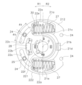
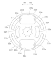
図1は、本発明の一実施形態によるトルクリミッタ付きダンパ装置1(以下、単に「ダンパ装置」と記載する場合もある)の断面図である。また、図2はダンパ装置1の正面図であり、一部の部材を取り外して、又は部材の一部を削除して示している。図1において、O-O線は回転軸である。図1において、ダンパ装置1の左側にエンジンが配置され、右側に電動機や変速装置等を含む駆動ユニットが配置される。
[overall structure]
FIG. 1 is a sectional view of a
なお、以下の説明において、軸方向とは、ダンパ装置1の回転軸Oが延びる方向である。また、円周方向とは、回転軸Oを中心とした円の円周方向であり、径方向とは、回転軸Oを中心とした円の径方向である。なお、円周方向とは、回転軸Oを中心とした円の円周方向に完全に一致している必要はなく、例えば、図2の上部に示された窓部及び窓孔を基準とした左右方向も含む概念である。また、径方向とは、回転軸Oを中心とした円の直径方向に完全に一致している必要はなく、例えば、図2の上部に示された窓部及び窓孔を基準とした上下方向も含む概念である。
Note that in the following description, the axial direction is the direction in which the rotation axis O of the
このダンパ装置1は、図示しないフライホイールと駆動ユニットの入力軸との間に設けられ、エンジンと駆動ユニットとの間で伝達されるトルクを制限するとともに、回転変動を減衰するための装置である。ダンパ装置1は、トルクリミッタユニット10と、ダンパユニット20と、を有している。
This
[トルクリミッタユニット10]
トルクリミッタユニット10は、ダンパユニット20の外周側に配置されている。トルクリミッタユニット10は、フライホイールとダンパユニット20との間で伝達されるトルクを制限する。トルクリミッタユニット10は、第1サイドプレート11及び第2サイドプレート12と、摩擦ディスク13と、プレッシャプレート14と、コーンスプリング15と、を有している。
[Torque limiter unit 10]
The
第1サイドプレート11と第2サイドプレート12とは複数のリベットによって互いに固定されている。摩擦ディスク13は、コアプレート131及び1対の摩擦部材132を有している。プレッシャプレート14及びコーンスプリング15は、第1サイドプレート11と摩擦ディスク13との間に配置されている。コーンスプリング15は、プレッシャプレート14を介して摩擦ディスク13を第2サイドプレート12に押圧している。
The
[ダンパユニット20]
ダンパユニット20は、入力側プレート21(第1回転体の一例)と、ハブフランジ22(第2回転体の一例)と、入力側プレート21とハブフランジ22との間に配置されたダンパ部23と、から構成されている。
[Damper unit 20]
The
<入力側プレート21>
入力側プレート21は、第1プレート211と第2プレート212とを有している(以下、第1プレート211及び第2プレート212を併せて「入力側プレート21」と記載する場合もある)。第1プレート211及び第2プレート212は、ともに中心孔を有する環状の部材である。第1プレート211と第2プレート212とは、4個のストップピン24によって、軸方向に所定の間隔をあけて互いに固定されている。したがって、第1プレート211と第2プレート212とは、軸方向及び回転方向に相対的に移動不能である。また、第1プレート211には、ストップピン24によって摩擦ディスク13のコアプレート131の内周部が固定されている。
<
The
第1プレート211及び第2プレート212には、それぞれ1対の第1窓部21a(第1収容部の一例)及び第2窓部21bが形成されている。1対の第1窓部21aは、回転軸Oを挟んで対向して配置されている。図2では、第2プレート212の第1窓部21a及び第2窓部21bが示されているが、第1プレート211の第1窓部及び第2窓部も同様の構成である。1対の第1窓部21aは、それぞれのプレート211,212を切り起こして形成されており、円周方向の両端面に押圧面21c(第1押圧面の一例)を有し、外周縁及び内周縁にそれぞれ支持部を有している。また、1対の第2窓部21bは、第1窓部とは90°の間隔をあけて、回転軸Oを挟んで対向して配置されている。1対の第2窓部21bは、軸方向に貫通する矩形の開口であり、円周方向の両端面に押圧面21dを有している。
A pair of
<ハブフランジ22>
ハブフランジ22は、入力側プレート21からのトルクを出力側の装置に伝達するための部材である。ハブフランジ22は、ハブ221とフランジ222とを有している。ハブ221とフランジ222とは、図2に示すように、複数の歯と、この歯が噛み合う複数の凹部と、によって一体化されている。
<
The
ハブ221は筒状の部材であり、第1プレート211及び第2プレート212の中心孔内に配置されている。ハブ221の内周部にはスプライン孔が形成されており、このスプライン孔に出力側の部材がスプライン係合可能である。
The
フランジ222は、図2及び図3に示すように、円板状に形成され、第1プレート211と第2プレート212との軸方向間に配置されている。フランジ222は、中心孔と、それぞれ1対の第1窓孔22a(第2収容部の一例)及び第2窓孔22bと、4個のストッパ用孔22cと、を有している。
As shown in FIGS. 2 and 3, the
第1窓孔22aは、回転軸Oを挟んで対向して配置されており、第1プレート211及び第2プレート212の第1窓部21aと対応する位置に形成されている。第1窓孔22aは、円周方向の両端面に押圧面22d(第1押圧面の一例)を有している。そして、各押圧面22dは、径方向の中心部に、対向する押圧面22dに向かって膨らむように突出する突出部22eを有している。
The
第2窓孔22bは、第1窓孔22aとは90°の間隔をあけて、回転軸Oを挟んで対向して配置されている。すなわち、第2窓孔22bは、第1プレート211及び第2プレート212の第2窓部21bと対応する位置に形成されている。第2窓孔22bは円弧状に形成されており、第2窓孔22bのピッチ径(孔の径方向の幅の中央位置の半径)は、第1窓孔22aの径方向の中心位置よりも径方向内側に位置している。第2窓孔22bは、円周方向の両端面に押圧面22fを有しており、両押圧面22f間の距離は、入力側プレート21の第2窓部21bの両押圧面21d間の距離より長く設定されている。
The
ストッパ用孔22cは、第1窓孔22aの円周方向の両側において、円弧状に延びる長孔である。ストッパ用孔22cの第1窓孔22aから離れた側の端部は、第2窓孔22bの径方向外側にまで延びている。また、ストッパ用孔22cの第1窓孔22aに近い方の端部は、第1窓孔22aの突出部22eに向かって延びている。具体的には、ストッパ用孔22cの第1窓孔22a側の端部は、直線Lに到達している。ここで、直線Lは、第1窓孔22aの突出部22eが形成されていない外周側の端面と内周側の端面とをつなぐ直線である。
The
このような構成では、第1窓孔22aに突出部22eが形成されていない場合に比較して、ストッパ用孔22cの第1窓孔22a側の端部を、より長く延ばして形成することができる。この結果、第1窓孔22aを挟む1対のストップピン24の間の角度を、90度に近づけることができる。なお、4つのストッパ用孔22cのピッチ径は同じである。すなわち、4つのストッパ用孔22cは、同一円周上に形成されている。
In such a configuration, the end of the
また、ストッパ用孔22cにはストップピン24が軸方向に貫通している。このため、入力側プレート21とハブフランジ22とは、ストップピン24がストッパ用孔22c内において移動可能な範囲で相対回転可能である。言い換えれば、ストップピン24とストッパ用孔22cとによってストッパ機構25が構成されており、入力側プレート21とハブフランジ22とは、ストップピン24がストッパ用孔22cの端面に当接することによって、互いの相対回転が禁止される。
Further, a
<ダンパ部23>
ダンパ部23は、入力側プレート21とハブフランジ22とを回転方向に弾性的に連結するための機構であり、図1及び図2に示すように、それぞれ2個のコイルスプリング27及び樹脂部材28と、コイルスプリング27の端面を支持する1対のスプリングシート30と、ヒス発生機構31(図1参照)と、を有している。
<
The
コイルスプリング27はフランジ222の第1窓孔22aに収容され、樹脂部材28はフランジ222の第2窓孔22bに収容されている。また、コイルスプリング27及び樹脂部材28は、第1プレート211及び第2プレート212の各窓部21a,21bによって、軸方向及び径方向に支持されている。
The
なお、樹脂部材28は、入力側プレート21の第2窓部21bに対して、円周方向に隙間なく配置されている。一方、樹脂部材28は、フランジ222の第2窓孔22bの円周方向の幅よりも短い。すなわち、入力側プレート21とハブフランジ22とが相対回転していない(捩り角度「0」)の中立時においては、樹脂部材28の両端部と、フランジ222の第2窓孔22bの押圧面22fと、の間には、隙間(隙間の詳細については後述)が形成されている。
Note that the
スプリングシート30は、フランジ222の第1窓孔22aの円周方向の両端部に配置されている。スプリングシート30は、コイルスプリング27の端面を支持するとともに、コイルスプリング27の外周部の一部(円周方向の両端部)を支持する。
The spring seats 30 are arranged at both ends of the
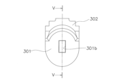
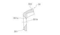
図4及び図5に示すように、スプリングシート30は、端面支持部301と、外周支持部302と、を有している。なお、図4はスプリングシート30の側面図(円周方向の一方側から視た図)であり、図5は図4のV-V線断面図である。
As shown in FIGS. 4 and 5, the
端面支持部301は、コイルスプリング27の端面を支持するとともに、入力側プレート21の第1窓部21aの押圧面21c及びフランジ222の第1窓孔22aの押圧面22dに支持されている。端面支持部301の、第1窓孔22aの押圧面22dに支持されている面には、図5に示すように、コイルスプリング27側に向かって円弧状に凹む凹部301aが形成されている。また、この凹部301aの中央部、すなわち、径方向の中央部でかつ軸方向の中央部に、円周方向に貫通する孔301bを有している。そして、フランジ222の第1窓孔22aの突出部22eが、この凹部301aに嵌まり込んでいる。
The end
以上のように、コイルスプリング27は、第1プレート211及び第2プレート212の第1窓部21aと、フランジ222の第1窓孔22aと、にスプリングシート30を介して円周方向に隙間なく収容されている。
As described above, the
外周支持部302は、端面支持部301の外周端部から円周方向に延びて形成されている。この外周支持部302は、コイルスプリング27の両端部の外周部と、第1窓部21a及び第1窓孔22aの内周面と、の間に配置されている。このため、コイルスプリング27が遠心力によって、あるいは圧縮された状態で、外周側に移動しても、コイルスプリング27と第1窓部21a及び第1窓孔22aとの接触を避けることができる。
The outer
ヒス発生機構31は、第1プレート211及び第2プレート212と、ハブフランジ22と、の軸方向間に配置されている。ヒス発生機構31は、図1に示すように、第1ブッシュ41と、第2ブッシュ42と、第3ブッシュ43と、コーンスプリング44と、を有している。
The
第1ブッシュ41及び第2ブッシュ42は、ハブ221の外周面において、第1プレート211の内周端部とフランジ222との軸方向間に配置されている。第2ブッシュ42は、ハブ221と相対回転不能に係合しており、第1ブッシュ41との間で摩擦接触する。第3ブッシュ43は、第2プレート212の内周端部とフランジ222との軸方向間に配置されている。第3ブッシュ43は第2プレート212と相対回転不能に係合しており、フランジ222と摩擦接触する。コーンスプリング44は、第3ブッシュ43と第2プレート212との間に圧縮された状態で配置されている。
The
以上のような構成によって、第1プレート211及び第2プレート212と、ハブフランジ22と、が相対回転した際に、ヒステリシストルクが発生する。
With the above configuration, hysteresis torque is generated when the
[動作]
エンジンからフライホイールに伝達されたトルクは、トルクリミッタユニット10を介してダンパユニット20に入力される。ダンパユニット20では、トルクリミッタユニット10の摩擦ディスク13が固定されている入力側プレート21にトルクが入力され、このトルクは、コイルスプリング27及び樹脂部材28を介してハブフランジ22に伝達される。そして、ハブフランジ22から、出力側の電動機、発電機、変速機等に動力が伝達される。
[motion]
Torque transmitted from the engine to the flywheel is input to the
また、例えば、エンジン始動時においては、出力側の慣性量が大きいために、出力側からエンジンに過大なトルクが伝達される場合がある。このような場合は、トルクリミッタユニット10によってエンジン側に伝達されるトルクが所定値以下に制限される。
Further, for example, when the engine is started, an excessive amount of torque may be transmitted from the output side to the engine because the amount of inertia on the output side is large. In such a case, the torque transmitted to the engine side by the
<正側捩り特性>
ダンパユニット20における正側の捩り特性、すなわち、エンジンからトルクが入力された場合(正側トルクの入力)の特性について説明する。
<Positive torsion characteristics>
The positive side torsional characteristics of the
正側トルクが入力されると、図2において、入力側プレート21はR1方向に回転する。このため、2つのコイルスプリング27は、入力側プレート21の第1窓部21aのR2側の押圧面21cに支持されているスプリングシート30と、フランジ222の第1窓孔22aのR1側の押圧面22dに支持されているスプリングシート30と、の間で圧縮される。
When the positive side torque is input, the
なお、図2に示すように、樹脂部材28は、中立時において、入力側プレート21の第2窓部21bに隙間なく支持されているが、フランジ222の第2窓孔22bにおいては、R1側及びR2側にそれぞれθ1の円周方向隙間が存在している。また、ストップピン24と各ストッパ用孔22cとの間には、R1側及びR2側にθ2の円周方向隙間が存在している。ここで、各円周方向隙間(以下、単に「隙間」と記載する)の関係は、以下のように設定されている。
As shown in FIG. 2, the
θ1<θ2
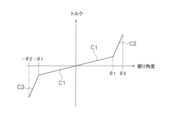
以上のような隙間の設定により、入力側プレート21とハブフランジ22との捩り角度(以下、「捩り角度」と記載した場合、入力側プレート21とハブフランジ22との捩り角度である)がθ1になるまでは、樹脂部材28は圧縮されない。そして、捩り角度がθ1を超えると、樹脂部材28は、入力側プレート21の第2窓部21bのR2側押圧面21dと、フランジ222の第2窓孔22bのR1側押圧面22fとの間で圧縮される。このため、正側の捩り特性は、図6で示すように、捩り角度がθ1までは特性C1となり、捩り角度がθ1を超えると特性C2となる。
θ1<θ2
By setting the gap as described above, the torsion angle between the
また、捩り角度がθ2になると、ストッパ用孔22cのR1側の端面にストップピン24が当接し、入力側プレート21とハブフランジ22との互いの相対回転が禁止される。
Further, when the torsion angle reaches θ2, the
<負側捩り特性>
ダンパユニット20における負側の捩り特性、すなわち、駆動ユニット側から逆にトルクが入力された場合(負側トルクの入力)の特性について説明する。
<Negative torsion characteristics>
The negative side torsional characteristics of the
負側トルクが入力されると、図2において、ハブフランジ22は入力側プレート21に対してR1方向に回転する。このため、2つのコイルスプリング27は、ハブフランジ22の第1窓孔22aのR2側押圧面22dに装着されたスプリングシート30と、入力側プレート21の第1窓部21aのR1側押圧面21cに装着されたスプリングシート30と、の間で圧縮される。
When negative side torque is input, the
樹脂部材28の作動については、正側トルクが入力された場合と同様である。すなわち、捩り角度が-θ1になるまでは圧縮されず、捩り角度が-θ1以下では、図6に示すように、低剛性の捩り特性C1となる。また、捩り角度が-θ1になると、樹脂部材28は、ハブフランジ22の第2窓孔22bのR2側押圧面22fと、入力側プレート21の第2窓部21bのR1側押圧面21dと、の間で圧縮され始める。このため、捩り角度が-θ1を超えると、図6に示すように、高剛性の捩り特性C2となる。
The operation of the
捩り角度が-θ2になると、ストップピン24がストッパ用孔22cのR2側端面に当接し、入力側プレート21とハブフランジ22との互いの相対回転が禁止される。
When the twist angle reaches -θ2, the
このような実施形態では、スプリングシート30に凹部301aが形成され、この凹部301aに、フランジ222の第1窓孔22aに形成された突出部22eが嵌まり込んでいる。そして、この突出部22eに向かってストッパ用孔22cの端部が延びている。このため、ストッパ用孔22cの円周方向の長さを長くすることができる。すなわち、スプリングシート30に凹部301aがなく、窓孔の端面が1つの平面で形成されている場合(突出部がない場合)に比較して、入力側プレート21とハブフランジ22との捩り角度を大きくすること(すなわち、広角化)が可能になる。
In this embodiment, a
また、同様の理由により、フランジ222の第1窓孔22aの両側のストッパ用孔22cの端部を互いに近づけることができる。この結果、第1窓孔22aの両側のストップピン24の間の角度を90度に近づけることができ、入力側プレート21及びハブフランジ22の強度の不均一性を抑えることができる。
Further, for the same reason, the ends of the stopper holes 22c on both sides of the
[他の実施形態]
本発明は以上のような実施形態に限定されるものではなく、本発明の範囲を逸脱することなく種々の変形又は修正が可能である。
[Other embodiments]
The present invention is not limited to the embodiments described above, and various changes and modifications can be made without departing from the scope of the present invention.
(a)前記実施形態では、ハブフランジ22を、ハブ221とフランジ222の2つの部材により構成したが、1つの部材によって構成してもよい。
(a) In the embodiment described above, the
(b)前記実施形態では、コイルスプリングの両端部にスプリングシートを設けたが、コイルスプリングの一方の端部にのみスプリングシートを設けてもよい。また、コイルスプリングの一方の端部に本発明のスプリングシートを設け、他方の端部に別の従来周知のスプリングシートを設けてもよい。 (b) In the above embodiment, the spring seat was provided at both ends of the coil spring, but the spring seat may be provided only at one end of the coil spring. Alternatively, the spring seat of the present invention may be provided at one end of the coil spring, and another conventionally known spring seat may be provided at the other end.
(c)弾性部材の構成は、2つのコイルスプリング及び2つの樹脂部材に限定されない。例えば、すべての弾性部材をコイルスプリングにしてもよく、また個数は限定されない。 (c) The configuration of the elastic member is not limited to two coil springs and two resin members. For example, all the elastic members may be coil springs, and the number is not limited.
(d)前記実施形態では、本発明をトルクリミッタ付きダンパ装置に適用したが、他のダンパ装置にも同様に適用することができる。 (d) In the embodiments described above, the present invention was applied to a damper device with a torque limiter, but it can be similarly applied to other damper devices.
(e)捩り特性は図6に示した特性に限定されない。 (e) Torsional characteristics are not limited to those shown in FIG.
21 入力側プレート(第1回転体)
211 第1プレート
212 第2プレート
21a 第1窓部(第1収容部)
21c 押圧面(第1押圧面)
22 ハブフランジ(第2回転体)
22a 第1窓孔(第2収容部)
22c ストッパ用孔
22d 押圧面(第2押圧面)
22e 突出部
24 ストップピン
25 ストッパ機構
27 コイルスプリング(弾性部材)
28 樹脂部材(弾性部材)
30 スプリングシート
301 端面支持部
301a 凹部
301b 孔
302 外周支持部
21 Input side plate (first rotating body)
211
21c Pressing surface (first pressing surface)
22 Hub flange (second rotating body)
22a First window hole (second storage part)
28 Resin member (elastic member)
30
3 01a Recessed
Claims (4)
前記第1回転体と相対回転可能であり、複数の第2収容部を有し、前記第2収容部は円周方向の両端面に第2押圧面を有する第2回転体と、
前記第1収容部及び前記第2収容部に収容され、前記第1回転体と前記第2回転体とを回転方向に弾性的に連結する複数の弾性部材と、
前記第1回転体に設けられたストップ部材と、前記第2回転体に形成され前記ストップ部材が貫通し円周方向に長いストッパ用孔と、を有するストッパ機構と、
前記第2回転体の第2収容部に配置され、複数の前記弾性部材のうちの少なくとも1つの弾性部材の少なくとも一方の端面を支持するスプリングシートと、
を備え、
前記スプリングシートは、端面支持部と、外周支持部と、を有し、
前記端面支持部は、径方向の中央部に、前記弾性部材側に向かって凹む凹部を有し、前記弾性部材の端面を支持するとともに、前記第1押圧面及び前記第2押圧面に支持されるものであり、
前記外周支持部は、前記弾性部材の径方向外側部の一部を支持するとともに、前記第2回転体の第2収容部の外周側の内壁によって支持されており、
前記第2回転体は、前記第2収容部の少なくとも一方の第2押圧面に、円周方向に突出する突出部を有しており、前記突出部は前記スプリングシートの凹部に嵌まり込み、
前記ストッパ用孔の円周方向の一方の端部は、前記突出部に向かって延びている、
ダンパ装置。
a first rotating body having a plurality of first accommodating parts, the first accommodating parts having first pressing surfaces on both end faces in the circumferential direction;
a second rotating body that is rotatable relative to the first rotating body and has a plurality of second accommodating parts, the second accommodating parts having second pressing surfaces on both end faces in the circumferential direction;
a plurality of elastic members that are accommodated in the first accommodating part and the second accommodating part and elastically connect the first rotating body and the second rotating body in the rotational direction;
a stopper mechanism having a stop member provided on the first rotating body; and a stopper hole formed on the second rotating body and extending in the circumferential direction through which the stop member passes;
a spring seat that is disposed in a second housing portion of the second rotating body and supports at least one end surface of at least one of the plurality of elastic members;
Equipped with
The spring seat has an end support portion and an outer peripheral support portion,
The end face support part has a concave part recessed toward the elastic member in a radial center part, supports the end face of the elastic member, and is supported by the first pressing surface and the second pressing surface. It is
The outer peripheral support part supports a part of the radially outer part of the elastic member, and is supported by an inner wall on the outer peripheral side of the second housing part of the second rotating body,
The second rotating body has a protrusion that protrudes in the circumferential direction on at least one second pressing surface of the second accommodating part, and the protrusion fits into the recess of the spring seat,
One circumferential end of the stopper hole extends toward the protrusion.
damper device.
The damper device according to claim 1, wherein the recess has a hole penetrating in the circumferential direction.
前記第2回転体は、前記第1プレートと前記第2プレートの軸方向間に配置されている、
請求項1又は2に記載のダンパ装置。
The first rotating body has a first plate and a second plate that are spaced apart in the axial direction,
The second rotating body is disposed between the first plate and the second plate in the axial direction.
The damper device according to claim 1 or 2.
Priority Applications (3)
| Application Number | Priority Date | Filing Date | Title |
|---|---|---|---|
| JP2020030441A JP7429130B2 (en) | 2020-02-26 | 2020-02-26 | Spring seat and damper device |
| CN202110098846.3A CN113309816A (en) | 2020-02-26 | 2021-01-25 | Spring seat and vibration damping device |
| US17/158,339 US11608862B2 (en) | 2020-02-26 | 2021-01-26 | Spring seat and damper device |
Applications Claiming Priority (1)
| Application Number | Priority Date | Filing Date | Title |
|---|---|---|---|
| JP2020030441A JP7429130B2 (en) | 2020-02-26 | 2020-02-26 | Spring seat and damper device |
Publications (3)
| Publication Number | Publication Date |
|---|---|
| JP2021134835A JP2021134835A (en) | 2021-09-13 |
| JP2021134835A5 JP2021134835A5 (en) | 2023-02-03 |
| JP7429130B2 true JP7429130B2 (en) | 2024-02-07 |
Family
ID=77365950
Family Applications (1)
| Application Number | Title | Priority Date | Filing Date |
|---|---|---|---|
| JP2020030441A Active JP7429130B2 (en) | 2020-02-26 | 2020-02-26 | Spring seat and damper device |
Country Status (3)
| Country | Link |
|---|---|
| US (1) | US11608862B2 (en) |
| JP (1) | JP7429130B2 (en) |
| CN (1) | CN113309816A (en) |
Citations (3)
| Publication number | Priority date | Publication date | Assignee | Title |
|---|---|---|---|---|
| JP2002340095A (en) | 2001-05-15 | 2002-11-27 | Exedy Corp | Damper mechanism |
| JP2002372099A (en) | 2001-06-13 | 2002-12-26 | Exedy Corp | Damper mechanism |
| JP2017187142A (en) | 2016-04-08 | 2017-10-12 | トヨタ自動車株式会社 | Spring holding member of damper device |
Family Cites Families (4)
| Publication number | Priority date | Publication date | Assignee | Title |
|---|---|---|---|---|
| US2760360A (en) * | 1951-12-05 | 1956-08-28 | Fichtel & Sachs Ag | Automobile clutch |
| US5401213A (en) * | 1993-02-04 | 1995-03-28 | General Motors Corporation | Clutch and damper assembly |
| JP2002213535A (en) * | 2001-01-18 | 2002-07-31 | Exedy Corp | Damper mechanism |
| JP2011226572A (en) | 2010-04-21 | 2011-11-10 | Valeo Unisia Transmission Kk | Damper device with torque limiter, and mounting structure thereof |
-
2020
- 2020-02-26 JP JP2020030441A patent/JP7429130B2/en active Active
-
2021
- 2021-01-25 CN CN202110098846.3A patent/CN113309816A/en active Pending
- 2021-01-26 US US17/158,339 patent/US11608862B2/en active Active
Patent Citations (3)
| Publication number | Priority date | Publication date | Assignee | Title |
|---|---|---|---|---|
| JP2002340095A (en) | 2001-05-15 | 2002-11-27 | Exedy Corp | Damper mechanism |
| JP2002372099A (en) | 2001-06-13 | 2002-12-26 | Exedy Corp | Damper mechanism |
| JP2017187142A (en) | 2016-04-08 | 2017-10-12 | トヨタ自動車株式会社 | Spring holding member of damper device |
Also Published As
| Publication number | Publication date |
|---|---|
| JP2021134835A (en) | 2021-09-13 |
| US11608862B2 (en) | 2023-03-21 |
| CN113309816A (en) | 2021-08-27 |
| US20210262527A1 (en) | 2021-08-26 |
Similar Documents
| Publication | Publication Date | Title |
|---|---|---|
| JP6010476B2 (en) | Dynamic damper device | |
| JP6828440B2 (en) | Damper device | |
| JP7418702B2 (en) | damper device | |
| JP7429130B2 (en) | Spring seat and damper device | |
| JP7427472B2 (en) | Spring seat and damper device | |
| JP7398980B2 (en) | damper device | |
| JP7340403B2 (en) | Torque limiter and power transmission device | |
| JP7449762B2 (en) | damper device | |
| JP7422617B2 (en) | Damper device with torque limiter | |
| JP2022095172A (en) | Damper device | |
| JP7477396B2 (en) | Damper Device | |
| JP7422618B2 (en) | damper device | |
| JP7473419B2 (en) | Damper Device | |
| US6168526B1 (en) | Damper disk assembly having integral retaining plate connecting means | |
| US20230034082A1 (en) | Damper device | |
| JP7376334B2 (en) | damper device | |
| JP7002402B2 (en) | Damper device | |
| JP7148419B2 (en) | damper device | |
| JPH11173380A (en) | Damper disc assembly | |
| JPH11173381A (en) | Damper | |
| JP2023005033A (en) | damper device | |
| JP2023179885A (en) | damper device | |
| JP2017172707A (en) | Torque fluctuation absorption device | |
| JP2023023092A (en) | Hub flange and damper device | |
| JP2021131152A (en) | Damper device |
Legal Events
| Date | Code | Title | Description |
|---|---|---|---|
| A521 | Request for written amendment filed |
Free format text: JAPANESE INTERMEDIATE CODE: A523 Effective date: 20230124 |
|
| A621 | Written request for application examination |
Free format text: JAPANESE INTERMEDIATE CODE: A621 Effective date: 20230124 |
|
| A977 | Report on retrieval |
Free format text: JAPANESE INTERMEDIATE CODE: A971007 Effective date: 20230824 |
|
| A131 | Notification of reasons for refusal |
Free format text: JAPANESE INTERMEDIATE CODE: A131 Effective date: 20230829 |
|
| A521 | Request for written amendment filed |
Free format text: JAPANESE INTERMEDIATE CODE: A523 Effective date: 20231012 |
|
| TRDD | Decision of grant or rejection written | ||
| A01 | Written decision to grant a patent or to grant a registration (utility model) |
Free format text: JAPANESE INTERMEDIATE CODE: A01 Effective date: 20240116 |
|
| A61 | First payment of annual fees (during grant procedure) |
Free format text: JAPANESE INTERMEDIATE CODE: A61 Effective date: 20240126 |
|
| R150 | Certificate of patent or registration of utility model |
Ref document number: 7429130 Country of ref document: JP Free format text: JAPANESE INTERMEDIATE CODE: R150 |