JP2022013151A - Housing of electric connection box - Google Patents
Housing of electric connection box Download PDFInfo
- Publication number
- JP2022013151A JP2022013151A JP2020115518A JP2020115518A JP2022013151A JP 2022013151 A JP2022013151 A JP 2022013151A JP 2020115518 A JP2020115518 A JP 2020115518A JP 2020115518 A JP2020115518 A JP 2020115518A JP 2022013151 A JP2022013151 A JP 2022013151A
- Authority
- JP
- Japan
- Prior art keywords
- wall
- case
- cover
- sealing surface
- side sealing
- Prior art date
- Legal status (The legal status is an assumption and is not a legal conclusion. Google has not performed a legal analysis and makes no representation as to the accuracy of the status listed.)
- Pending
Links
- 238000012856 packing Methods 0.000 claims abstract description 34
- XLYOFNOQVPJJNP-UHFFFAOYSA-N water Substances O XLYOFNOQVPJJNP-UHFFFAOYSA-N 0.000 claims abstract description 32
- 230000000903 blocking effect Effects 0.000 claims abstract description 13
- 229910052751 metal Inorganic materials 0.000 claims abstract description 8
- 239000002184 metal Substances 0.000 claims abstract description 8
- 238000007789 sealing Methods 0.000 claims description 53
- 150000003839 salts Chemical class 0.000 abstract description 9
- 230000006866 deterioration Effects 0.000 abstract description 2
- 229910052782 aluminium Inorganic materials 0.000 description 2
- XAGFODPZIPBFFR-UHFFFAOYSA-N aluminium Chemical compound [Al] XAGFODPZIPBFFR-UHFFFAOYSA-N 0.000 description 2
- 230000007797 corrosion Effects 0.000 description 2
- 238000005260 corrosion Methods 0.000 description 2
- 230000000694 effects Effects 0.000 description 2
- 230000005484 gravity Effects 0.000 description 2
- 238000012986 modification Methods 0.000 description 1
- 230000004048 modification Effects 0.000 description 1
- 230000000149 penetrating effect Effects 0.000 description 1
- 239000000758 substrate Substances 0.000 description 1
Images


Classifications
-
- H—ELECTRICITY
- H02—GENERATION; CONVERSION OR DISTRIBUTION OF ELECTRIC POWER
- H02G—INSTALLATION OF ELECTRIC CABLES OR LINES, OR OF COMBINED OPTICAL AND ELECTRIC CABLES OR LINES
- H02G3/00—Installations of electric cables or lines or protective tubing therefor in or on buildings, equivalent structures or vehicles
- H02G3/02—Details
- H02G3/08—Distribution boxes; Connection or junction boxes
- H02G3/088—Dustproof, splashproof, drip-proof, waterproof, or flameproof casings or inlets
-
- H—ELECTRICITY
- H05—ELECTRIC TECHNIQUES NOT OTHERWISE PROVIDED FOR
- H05K—PRINTED CIRCUITS; CASINGS OR CONSTRUCTIONAL DETAILS OF ELECTRIC APPARATUS; MANUFACTURE OF ASSEMBLAGES OF ELECTRICAL COMPONENTS
- H05K5/00—Casings, cabinets or drawers for electric apparatus
- H05K5/0004—Casings, cabinets or drawers for electric apparatus comprising several parts forming a closed casing
-
- H—ELECTRICITY
- H05—ELECTRIC TECHNIQUES NOT OTHERWISE PROVIDED FOR
- H05K—PRINTED CIRCUITS; CASINGS OR CONSTRUCTIONAL DETAILS OF ELECTRIC APPARATUS; MANUFACTURE OF ASSEMBLAGES OF ELECTRICAL COMPONENTS
- H05K5/00—Casings, cabinets or drawers for electric apparatus
- H05K5/02—Details
- H05K5/0217—Mechanical details of casings
-
- H—ELECTRICITY
- H05—ELECTRIC TECHNIQUES NOT OTHERWISE PROVIDED FOR
- H05K—PRINTED CIRCUITS; CASINGS OR CONSTRUCTIONAL DETAILS OF ELECTRIC APPARATUS; MANUFACTURE OF ASSEMBLAGES OF ELECTRICAL COMPONENTS
- H05K5/00—Casings, cabinets or drawers for electric apparatus
- H05K5/02—Details
- H05K5/03—Covers
-
- H—ELECTRICITY
- H05—ELECTRIC TECHNIQUES NOT OTHERWISE PROVIDED FOR
- H05K—PRINTED CIRCUITS; CASINGS OR CONSTRUCTIONAL DETAILS OF ELECTRIC APPARATUS; MANUFACTURE OF ASSEMBLAGES OF ELECTRICAL COMPONENTS
- H05K5/00—Casings, cabinets or drawers for electric apparatus
- H05K5/04—Metal casings
-
- H—ELECTRICITY
- H05—ELECTRIC TECHNIQUES NOT OTHERWISE PROVIDED FOR
- H05K—PRINTED CIRCUITS; CASINGS OR CONSTRUCTIONAL DETAILS OF ELECTRIC APPARATUS; MANUFACTURE OF ASSEMBLAGES OF ELECTRICAL COMPONENTS
- H05K5/00—Casings, cabinets or drawers for electric apparatus
- H05K5/06—Hermetically-sealed casings
- H05K5/061—Hermetically-sealed casings sealed by a gasket held between a removable cover and a body, e.g. O-ring, packing
-
- H—ELECTRICITY
- H05—ELECTRIC TECHNIQUES NOT OTHERWISE PROVIDED FOR
- H05K—PRINTED CIRCUITS; CASINGS OR CONSTRUCTIONAL DETAILS OF ELECTRIC APPARATUS; MANUFACTURE OF ASSEMBLAGES OF ELECTRICAL COMPONENTS
- H05K5/00—Casings, cabinets or drawers for electric apparatus
- H05K5/06—Hermetically-sealed casings
- H05K5/069—Other details of the casing, e.g. wall structure, passage for a connector, a cable, a shaft
-
- B—PERFORMING OPERATIONS; TRANSPORTING
- B60—VEHICLES IN GENERAL
- B60R—VEHICLES, VEHICLE FITTINGS, OR VEHICLE PARTS, NOT OTHERWISE PROVIDED FOR
- B60R16/00—Electric or fluid circuits specially adapted for vehicles and not otherwise provided for; Arrangement of elements of electric or fluid circuits specially adapted for vehicles and not otherwise provided for
- B60R16/02—Electric or fluid circuits specially adapted for vehicles and not otherwise provided for; Arrangement of elements of electric or fluid circuits specially adapted for vehicles and not otherwise provided for electric constitutive elements
- B60R16/023—Electric or fluid circuits specially adapted for vehicles and not otherwise provided for; Arrangement of elements of electric or fluid circuits specially adapted for vehicles and not otherwise provided for electric constitutive elements for transmission of signals between vehicle parts or subsystems
- B60R16/0238—Electrical distribution centers
-
- H—ELECTRICITY
- H02—GENERATION; CONVERSION OR DISTRIBUTION OF ELECTRIC POWER
- H02G—INSTALLATION OF ELECTRIC CABLES OR LINES, OR OF COMBINED OPTICAL AND ELECTRIC CABLES OR LINES
- H02G3/00—Installations of electric cables or lines or protective tubing therefor in or on buildings, equivalent structures or vehicles
- H02G3/02—Details
- H02G3/08—Distribution boxes; Connection or junction boxes
- H02G3/14—Fastening of cover or lid to box
Abstract
Description
本開示は、電気接続箱の筐体に関する。 The present disclosure relates to a housing of an electrical junction box.
箱本体および蓋カバーからなる電気接続箱の防水シール構造として、従来、特開2001-238326号公報(下記特許文献1)に記載のものが知られている。特許文献1に記載の電気接続箱の防水シール構造では、箱本体と蓋カバーとの突き合わせ面にパッキンが装着され、箱本体は蓋カバーで閉塞されている。
As a waterproof seal structure of an electric connection box including a box body and a lid cover, the one described in Japanese Patent Application Laid-Open No. 2001-238326 (
上記のような電気接続箱を電気自動車等の車両のエンジンルームに配設すると、電気接続箱は塩水にさらされうる。毛細管現象によって塩水が電気接続箱のパッキンの外側に溜まった場合、水分が蒸発して塩分濃度が上昇する。電気接続箱が金属製である場合には、濃度の高い塩水によって電気接続箱の腐食が進み、防水性が低下するおそれがある。 If the electrical junction box as described above is arranged in the engine room of a vehicle such as an electric vehicle, the electrical junction box may be exposed to salt water. When salt water collects on the outside of the packing of the electrical connection box due to the capillary phenomenon, the water evaporates and the salinity increases. If the electrical junction box is made of metal, the electrical junction box may be corroded by high-concentration salt water, and the waterproof property may be deteriorated.
本開示は上記のような事情に基づいて完成されたものであって、塩水への曝露による防水性の低下が抑制された電気接続箱の筐体を提供することを目的とする。 The present disclosure has been completed based on the above circumstances, and an object of the present invention is to provide a housing of an electric junction box in which deterioration of waterproofness due to exposure to salt water is suppressed.
本開示の電気接続箱の筐体は、上下方向に開口する開口部を有する金属製のケースと、上方から前記開口部を塞ぐカバーと、前記開口部の孔縁部に設けられた溝部に装着される環状のパッキンと、を備え、前記溝部は、前記パッキンに下方から接触するケース側シール面と、前記ケース側シール面の径方向内側に位置して上方に突出して設けられた内側壁と、前記ケース側シール面の径方向外側に位置して上方に突出して設けられた外側壁と、を有し、前記カバーは、前記パッキンに上方から接触するカバー側シール面と、前記カバー側シール面の径方向外側に位置して下方に突出して設けられた止水壁と、を備え、前記止水壁と前記ケースの外面との間には、上下方向にのびる第1クリアランスが設けられ、前記止水壁と前記外側壁との間には、径方向にのびる第2クリアランスが設けられている、電気接続箱の筐体である。 The housing of the electrical junction box of the present disclosure is attached to a metal case having an opening that opens in the vertical direction, a cover that closes the opening from above, and a groove provided at the hole edge of the opening. An annular packing is provided, and the groove portion includes a case-side sealing surface that comes into contact with the packing from below, and an inner side wall that is located radially inside the case-side sealing surface and projects upward. The cover has a cover-side sealing surface that comes into contact with the packing from above and a cover-side seal that has an outer wall that is located radially outside the case-side sealing surface and is provided so as to project upward. It is provided with a waterproof wall that is located on the radial outer side of the surface and is provided so as to project downward, and a first clearance extending in the vertical direction is provided between the waterproof wall and the outer surface of the case. It is a housing of an electric junction box provided with a second clearance extending in the radial direction between the water blocking wall and the outer wall.
本開示によれば、塩水への曝露による防水性の低下が抑制された電気接続箱の筐体を提供することができる。 According to the present disclosure, it is possible to provide a housing of an electric connection box in which a decrease in waterproofness due to exposure to salt water is suppressed.
[本開示の実施形態の説明]
最初に本開示の実施態様を列挙して説明する。
[Explanation of Embodiments of the present disclosure]
First, embodiments of the present disclosure will be listed and described.
(1)本開示の電気接続箱の筐体は、上下方向に開口する開口部を有する金属製のケースと、上方から前記開口部を塞ぐカバーと、前記開口部の孔縁部に設けられた溝部に装着される環状のパッキンと、を備え、前記溝部は、前記パッキンに下方から接触するケース側シール面と、前記ケース側シール面の径方向内側に位置して上方に突出して設けられた内側壁と、前記ケース側シール面の径方向外側に位置して上方に突出して設けられた外側壁と、を有し、前記カバーは、前記パッキンに上方から接触するカバー側シール面と、前記カバー側シール面の径方向外側に位置して下方に突出して設けられた止水壁と、を備え、前記止水壁と前記ケースの外面との間には、上下方向に第1クリアランスが設けられ、前記止水壁と前記外側壁との間には、径方向に第2クリアランスが設けられている。ここで、径方向とは、開口部が構成する開口の中心を上下方向に貫く中心軸線に対する法線の方向のことであり、中心軸線に近い側を径方向内側、中心軸線から遠い側を径方向外側とする。 (1) The housing of the electric junction box of the present disclosure is provided at a metal case having an opening that opens in the vertical direction, a cover that closes the opening from above, and a hole edge of the opening. An annular packing to be attached to the groove portion is provided, and the groove portion is provided so as to have a case-side sealing surface that comes into contact with the packing from below and a case-side sealing surface that is located inside in the radial direction and projects upward. The cover has an inner side wall and an outer wall which is located radially outward of the case-side sealing surface and is provided so as to project upward, and the cover has a cover-side sealing surface that comes into contact with the packing from above. A waterproof wall is provided that is located on the radial outer side of the cover-side sealing surface and is provided so as to project downward, and a first clearance is provided in the vertical direction between the waterproof wall and the outer surface of the case. A second clearance is provided in the radial direction between the waterproof wall and the outer wall. Here, the radial direction is the direction of the normal line with respect to the central axis that penetrates the center of the opening formed by the opening in the vertical direction. The outside of the direction.
このような構成によると、外側壁が上方に突出して設けられているため、重力により水が外側壁を越えてケース側シール面やカバー側シール面まで到達しにくい。また、ケースとカバーの間には第1クリアランスと第2クリアランスとが設けられているため、毛細管現象が起こりにくく、水が外側壁の上側に到達することをさらに抑制できる。したがって、電気接続箱の筐体が塩水にさらされても、腐食による防水性の低下を抑えることができる。 According to such a configuration, since the outer wall is provided so as to project upward, it is difficult for water to reach the case-side sealing surface or the cover-side sealing surface beyond the outer wall due to gravity. Further, since the first clearance and the second clearance are provided between the case and the cover, the capillary phenomenon is less likely to occur, and water can be further suppressed from reaching the upper side of the outer wall. Therefore, even if the housing of the electrical connection box is exposed to salt water, it is possible to suppress a decrease in waterproofness due to corrosion.
(2)前記ケース側シール面は、前記ケースの外面のうち前記止水壁と対向する面よりも、上方に設けられていることが好ましい。 (2) It is preferable that the case-side sealing surface is provided above the outer surface of the case facing the water blocking wall.
このような構成によると、ケースの外面に対して外側壁をより上方に突出して設けることができ、水が外側壁を越えてケース側シール面やカバー側シール面まで到達しにくくなる。 According to such a configuration, the outer wall can be provided so as to project upward with respect to the outer surface of the case, and it becomes difficult for water to reach the case-side sealing surface or the cover-side sealing surface beyond the outer wall.
(3)前記カバー側シール面は、前記内側壁の上端と前記外側壁の上端との双方に面接触していることが好ましい。 (3) It is preferable that the cover-side sealing surface is in surface contact with both the upper end of the inner side wall and the upper end of the outer wall.
このような構成によると、ケースとカバーが2つの接触面を有するため、ケースに対して安定してカバーを取り付けることができる。 According to such a configuration, since the case and the cover have two contact surfaces, the cover can be stably attached to the case.
[本開示の実施形態の詳細]
以下に、本開示の実施形態について説明する。本開示はこれらの例示に限定されるものではなく、特許請求の範囲によって示され、特許請求の範囲と均等の意味および範囲内での全ての変更が含まれることが意図される。
[Details of Embodiments of the present disclosure]
Hereinafter, embodiments of the present disclosure will be described. The present disclosure is not limited to these examples, but is shown by the scope of claims and is intended to include all modifications within the meaning and scope equivalent to the scope of claims.
<実施形態>
本開示の実施形態について、図1から図7を参照しつつ説明する。本実施形態の電気接続箱の筐体1は、例えば、電気自動車やハイブリッド自動車等の車両に搭載され、車両に配索されるワイヤーハーネスの端末に接続されるようになっている(図示省略)。電気接続箱の筐体1の内部には、図示しない複数の電子部品が収容される。電気接続箱の筐体1は、車両の使用に際して塩水等の水にさらされる位置に配設される。
<Embodiment>
The embodiments of the present disclosure will be described with reference to FIGS. 1 to 7. The
[電気接続箱の筐体]
電気接続箱の筐体1は、図2に示すように、ケース10と、ケース10を上方(図示紙面手前方向)から塞ぐカバー20と、ケース10とカバー20との間に配されるパッキン30と、を備えている。
[Housing of electrical junction box]
As shown in FIG. 2, the
[ケース、開口部]
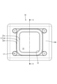
ケース10は、アルミニウム等の金属からなり、図1に示すように、直方体の箱状をなしている。ケース10は、天井壁10Aと、天井壁10Aに対向して下方に位置する底壁(図示せず)と、天井壁10Aと底壁とを接続する複数の側壁10Bと、を備えている。図3に示すように、天井壁10Aには、上下方向(図示紙面垂直方向)に開口した開口部12が設けられている。開口部12は、平面視で方形状をなしている。開口部12の図示紙面奥方におけるケース10の内側の空間は、内空間13とされている。
[Case, opening]
The
以下では、上下方向に直交する方向について径方向を用いて説明する。径方向とは、図7に示すように、開口部12が構成する開口の中心を上下方向に貫く中心軸線L1に対する法線の方向のことであり、中心軸線L1に近い側を径方向内側、中心軸線L1から遠い側を径方向外側とする。例えば、図示左方にのびる中心軸線L1の法線L2により径方向を考えると、相対的に図示右側が径方向内側、図示左側が径方向外側となる。
In the following, the directions orthogonal to the vertical direction will be described using the radial direction. As shown in FIG. 7, the radial direction is the direction of the normal line with respect to the central axis L1 penetrating the center of the opening formed by the
[溝部、ケース側シール面、内側壁、外側壁]
天井壁10Aにおける開口部12の孔縁部には、図3に示すように、開口部12の全周にわたって溝部11が設けられている。溝部11は、ケース側シール面14と、ケース側シール面14の径方向内側に位置する内側壁15と、ケース側シール面14の径方向外側に位置する外側壁16と、を有する。内側壁15の一部は、開口部12を構成している。ケース側シール面14は、図5及び図6に示すように、上下方向に垂直な面であり、天井壁10Aにおけるケース10の外面10Sよりも上方に設けられている。内側壁15及び外側壁16は、ケース側シール面14より上方に突出して設けられている。内側壁15の上端15A及び外側壁16の上端16Aは、同一の高さ位置に設けられ、上下方向に垂直な面を有する。溝部11には、パッキン30が嵌め込まれ、ケース側シール面14はパッキン30に下方から接触する。
[Groove, case side seal surface, inner side wall, outer wall]
As shown in FIG. 3, a
天井壁10Aにおける溝部11の径方向の外側には、4個のボルト締結部17が設けられている。ボルト締結部17は、内部にねじ加工がされ、ボルト40を締結できるようになっている。図示しないナットを内部に有する。図示しないが、ボルト締結部17の上端は、内側壁15の上端15A及び外側壁16の上端16Aと同じ高さ位置に設定されている。
Four
[パッキン]
パッキン30は、ゴム等の弾性部材からなり、図2に示すように、平面視で環状をなしている。パッキン30は、図5及び図6に示すように、上側と下側とにそれぞれ2つの山を有する断面形状をなし、溝部11に装着されるように形成されている。パッキン30の上下方向の寸法は、自然状態では、内側壁15及び外側壁16のケース側シール面14からの高さよりも大きく形成され、電気接続箱の筐体1の組み立ての際、パッキン30は、ケース側シール面14と後述するカバー側シール面21Aとにより上下方向から圧縮されるようになっている。
[rubber seal]
The packing 30 is made of an elastic member such as rubber, and has an annular shape in a plan view as shown in FIG. As shown in FIGS. 5 and 6, the packing 30 has a cross-sectional shape having two peaks on the upper side and the lower side, respectively, and is formed so as to be mounted on the
[カバー、カバー側シール面、止水壁]
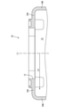
カバー20は、アルミニウム等の金属からなり、図1及び図4に示すように、上下方向に薄い板状をなしている。カバー20は、図4に示すように、長方形状をなし、カバー20の中央部はカバー本体部21とされている。カバー本体部21の四隅にはボルト締結のための貫通孔23が形成されている。カバー本体部21の下面(図示紙面手前側の面)は、カバー側シール面21Aとされている。カバー本体部21の外縁部には、止水壁22がカバー側シール面21Aより下方に突出して設けられている。カバー本体部21の外縁部には、さらに鍔部24が径方向外側にのびて設けられている。鍔部24は、図示紙面手前から見たとき、長方形状をなすカバー20の短辺に対応する位置に設けられている。
[Cover, seal surface on cover side, waterproof wall]
The
[第1クリアランス、第2クリアランス]
図5及び図6に示すように、カバー側シール面21Aは、溝部11に装着されたパッキン30の上端に接触し、ケース側シール面14とともにパッキン30を上下方向から圧縮する。カバー側シール面21Aは、内側壁15の上端15Aと外側壁16の上端16Aに面接触してボルト40により固定される。ボルト締結によって電気接続箱の筐体1が閉じられた状態(以下、閉止状態とする)では、止水壁22と天井壁10Aにおける外面10Sとの間には、上下方向に第1クリアランスCL1が設けられている。閉止状態において、止水壁22と外側壁16との間には、径方向に第2クリアランスCL2が設けられている。第1クリアランスCL1及び第2クリアランスCL2は、ともに1mm以上とすることが好ましい。これにより、水が毛細管現象により第1クリアランスCL1及び第2クリアランスCL2に浸入することが抑制できる。また、図6に示すように、鍔部24の下端は、止水壁22の下端よりも高く設けられており、同様に、鍔部24と天井壁10Aにおける外面10Sとの間における水の毛細管現象は起こりにくくなっている。
[1st clearance, 2nd clearance]
As shown in FIGS. 5 and 6, the cover-
[電気接続箱の筐体の組み立て]
ケース10の内空間13に基板や複数の電子部品(図示せず)が収容される。パッキン30がケース10の溝部11に装着される。貫通孔23とボルト締結部17を合わせるように、カバー20がケース10の上方から被せられる。ボルト40を貫通孔23に上方から挿通し、ボルト締結部17に対して締結することで、カバー20がケース10に取り付けられる。ボルト40を締結していくと、パッキン30はカバー側シール面21Aとケース側シール面14とによって上下方向から圧縮されていく。カバー側シール面21Aが内側壁15の上端15Aと外側壁16の上端16Aとの双方に面接触した閉止状態では、パッキン30は、カバー側シール面21Aとケース側シール面14とに水密に密着した状態となる。以上により、電気接続箱の筐体1の組み立ては完了する。
[Assembly of the housing of the electrical junction box]
A substrate and a plurality of electronic components (not shown) are housed in the
[実施形態の作用効果]
実施形態によれば、以下の作用、効果を奏する。
実施形態の電気接続箱の筐体1は、上下方向に開口する開口部12を有する金属製のケース10と、上方から開口部12を塞ぐカバー20と、開口部12の孔縁部に設けられた溝部11に装着される環状のパッキン30と、を備え、溝部11は、パッキン30に下方から接触するケース側シール面14と、ケース側シール面14の径方向内側に位置して上方に突出して設けられた内側壁15と、ケース側シール面14の径方向外側に位置して上方に突出して設けられた外側壁16と、を有し、カバー20は、パッキン30に上方から接触するカバー側シール面21Aと、カバー側シール面21Aの径方向外側に位置して下方に突出して設けられた止水壁22と、を備え、止水壁22とケース10の外面10Sとの間には、上下方向に第1クリアランスCL1が設けられ、止水壁22と外側壁16との間には、径方向に第2クリアランスCL2が設けられている。
[Action and effect of the embodiment]
According to the embodiment, the following actions and effects are exhibited.
The
上記の構成によれば、外側壁16が上方に突出して設けられているため、重力により水が外側壁16を越えてケース側シール面14やカバー側シール面21Aまで到達しにくい。また、ケース10とカバー20の間には第1クリアランスCL1と第2クリアランスCL2とが設けられているため、毛細管現象が起こりにくく、水が外側壁16の上側に到達することをさらに抑制できる。したがって、電気接続箱の筐体1が塩水にさらされても、腐食による防水性の低下を抑えることができる。
According to the above configuration, since the
実施形態では、ケース側シール面14は、ケース10の外面10Sのうち止水壁22と対向する面よりも、上方に設けられている。
In the embodiment, the case-
上記の構成によれば、ケース10の外面10Sに対して外側壁16をより上方に突出して設けることができ、水が外側壁16を越えてケース側シール面14やカバー側シール面21Aまで到達しにくくなる。
According to the above configuration, the
実施形態では、カバー側シール面21Aは、内側壁15の上端15Aと外側壁16の上端16Aとの双方に面接触している。
In the embodiment, the cover-
上記の構成によれば、ケース10とカバー20が2つの接触面を有するため、ケース10に対して安定してカバー20を取り付けることができる。
According to the above configuration, since the
<他の実施形態>
(1)上記実施形態では、内側壁15の上端15Aと外側壁16の上端16Aとは、同じ高さに設定されたが、これに限られることはなく、内側壁の上端と外側壁の上端とは、異なる高さに設定されてもよい。
(2)上記実施形態では、カバー20は鍔部24を備えていたが、これに限られることはなく、カバーは鍔部を備えていなくてもよい。
(3)上記実施形態では、パッキン30は上側と下側とにそれぞれ2つの山を有する断面形状をなして設けられたが、これに限られることはなく、パッキンの断面形状は、任意に設定されうる。
<Other embodiments>
(1) In the above embodiment, the
(2) In the above embodiment, the
(3) In the above embodiment, the packing 30 is provided in a cross-sectional shape having two peaks on the upper side and the lower side, respectively, but the present invention is not limited to this, and the cross-sectional shape of the packing is arbitrarily set. Can be done.
1: 電気接続箱の筐体
10: ケース
10A: 天井壁
10B: 側壁
10S: 外面
11: 溝部
12: 開口部
13: 内空間
14: ケース側シール面
15: 内側壁
15A,16A: 上端
16: 外側壁
17: ボルト締結部
20: カバー
21: カバー本体部
21A: カバー側シール面
22: 止水壁
23: 貫通孔
24: 鍔部
30: パッキン
40: ボルト
CL1: 第1クリアランス
CL2: 第2クリアランス
L1: 中心軸線
L2: 中心軸線の法線
1: Housing of electrical connection box 10:
Claims (3)
上方から前記開口部を塞ぐカバーと、
前記開口部の孔縁部に設けられた溝部に装着される環状のパッキンと、を備え、
前記溝部は、前記パッキンに下方から接触するケース側シール面と、前記ケース側シール面の径方向内側に位置して上方に突出して設けられた内側壁と、前記ケース側シール面の径方向外側に位置して上方に突出して設けられた外側壁と、を有し、
前記カバーは、前記パッキンに上方から接触するカバー側シール面と、前記カバー側シール面の径方向外側に位置して下方に突出して設けられた止水壁と、を備え、
前記止水壁と前記ケースの外面との間には、上下方向に第1クリアランスが設けられ、
前記止水壁と前記外側壁との間には、径方向に第2クリアランスが設けられている、電気接続箱の筐体。 A metal case with an opening that opens vertically,
A cover that closes the opening from above,
An annular packing attached to the groove provided at the hole edge of the opening is provided.
The groove portion has a case-side sealing surface that comes into contact with the packing from below, an inner side wall that is positioned radially inside the case-side sealing surface and is provided so as to project upward, and a radial outside of the case-side sealing surface. It has an outer wall, which is located at the top and is provided so as to project upwards.
The cover includes a cover-side sealing surface that comes into contact with the packing from above, and a waterproof wall that is located radially outside the cover-side sealing surface and is provided so as to project downward.
A first clearance is provided in the vertical direction between the water blocking wall and the outer surface of the case.
A housing of an electrical connection box in which a second clearance is provided in the radial direction between the water blocking wall and the outer wall.
Priority Applications (3)
| Application Number | Priority Date | Filing Date | Title |
|---|---|---|---|
| JP2020115518A JP2022013151A (en) | 2020-07-03 | 2020-07-03 | Housing of electric connection box |
| CN202110676993.4A CN113891587A (en) | 2020-07-03 | 2021-06-18 | Casing of electric connection box |
| US17/366,646 US11769993B2 (en) | 2020-07-03 | 2021-07-02 | Electrical junction box housing |
Applications Claiming Priority (1)
| Application Number | Priority Date | Filing Date | Title |
|---|---|---|---|
| JP2020115518A JP2022013151A (en) | 2020-07-03 | 2020-07-03 | Housing of electric connection box |
Publications (1)
| Publication Number | Publication Date |
|---|---|
| JP2022013151A true JP2022013151A (en) | 2022-01-18 |
Family
ID=79010268
Family Applications (1)
| Application Number | Title | Priority Date | Filing Date |
|---|---|---|---|
| JP2020115518A Pending JP2022013151A (en) | 2020-07-03 | 2020-07-03 | Housing of electric connection box |
Country Status (3)
| Country | Link |
|---|---|
| US (1) | US11769993B2 (en) |
| JP (1) | JP2022013151A (en) |
| CN (1) | CN113891587A (en) |
Citations (2)
| Publication number | Priority date | Publication date | Assignee | Title |
|---|---|---|---|---|
| JP2010259208A (en) * | 2009-04-24 | 2010-11-11 | Hitachi Automotive Systems Ltd | Storage device of electrical component, and storage device of inverter for vehicle |
| JP2019071732A (en) * | 2017-10-10 | 2019-05-09 | 株式会社デンソー | Seal structure of on-vehicle electronic component housing |
Family Cites Families (32)
| Publication number | Priority date | Publication date | Assignee | Title |
|---|---|---|---|---|
| US3825148A (en) * | 1972-09-25 | 1974-07-23 | Gen Electric | Hermetic sealing system for plastic tank and cover |
| US3974933A (en) * | 1975-11-14 | 1976-08-17 | General Signal Corporation | Explosion proof and watertight enclosure with inspectable means for verifying validity of reclosure |
| US4664281A (en) * | 1985-10-15 | 1987-05-12 | Killark Electric Manufacturing Co. | Explosion proof enclosure |
| JP2000115955A (en) * | 1998-10-01 | 2000-04-21 | Yazaki Corp | Waterproof structure for electrical connection box |
| JP2001238326A (en) * | 2000-02-23 | 2001-08-31 | Yazaki Corp | Waterproof sealing for electric junction box |
| JP2001326475A (en) * | 2000-05-15 | 2001-11-22 | Nec Corp | Waterproof structure of communication apparatus |
| US6831222B2 (en) * | 2002-08-14 | 2004-12-14 | Darrell Pastuch | Weatherproof junction box |
| JP2004158650A (en) * | 2002-11-06 | 2004-06-03 | Nec Corp | Electromagnetic wave shield and waterproof structure casing |
| JP4228955B2 (en) * | 2004-03-22 | 2009-02-25 | 住友電装株式会社 | Electrical junction box |
| JP4402526B2 (en) * | 2004-06-22 | 2010-01-20 | シンクレイヤ株式会社 | Electrical equipment housing |
| JP4365338B2 (en) * | 2005-03-17 | 2009-11-18 | トヨタ自動車株式会社 | Electronic component housing structure |
| TWI342180B (en) * | 2007-10-09 | 2011-05-11 | Asustek Comp Inc | Housing structure |
| CN101720180A (en) * | 2008-10-09 | 2010-06-02 | 大连晨光电气控制有限公司 | Sealing structure for sealing box |
| DE102009000103A1 (en) * | 2009-01-09 | 2010-07-15 | Robert Bosch Gmbh | Sealing a cable with a large outer diameter |
| DE102009005716B4 (en) * | 2009-01-22 | 2014-01-02 | Rittal Gmbh & Co. Kg | casing |
| JP5177690B2 (en) * | 2009-06-12 | 2013-04-03 | 日本メクトロン株式会社 | Waterproof gasket for small electronic equipment |
| JP2011071362A (en) * | 2009-09-28 | 2011-04-07 | Kyocera Corp | Metal casing for communication device |
| US8963000B2 (en) * | 2011-10-11 | 2015-02-24 | Hon Hai Precision Industry Co., Ltd. | Junction box having improved clips |
| JP5861427B2 (en) * | 2011-12-07 | 2016-02-16 | 富士通株式会社 | Gasket, waterproof structure, and electronic equipment |
| US8796548B2 (en) * | 2012-06-04 | 2014-08-05 | Seahorse Industries Ltd. | Underground utility box assembly |
| KR20140006392A (en) * | 2012-07-05 | 2014-01-16 | 엘에스산전 주식회사 | Electronic component box for vehicle |
| CN202857192U (en) * | 2012-09-10 | 2013-04-03 | 科博达技术有限公司 | Sealed shell |
| JP5932940B2 (en) * | 2014-10-17 | 2016-06-08 | Nok株式会社 | Rubber gasket |
| JP6492983B2 (en) * | 2015-06-03 | 2019-04-03 | 沖電気工業株式会社 | Electronic equipment casing |
| CN205260819U (en) * | 2015-11-30 | 2016-05-25 | 中冶南方(武汉)自动化有限公司 | Housing sealing structure |
| CN107889408B (en) * | 2017-12-08 | 2023-12-12 | 广东美的制冷设备有限公司 | Electric control box and air conditioner |
| CN207639018U (en) * | 2017-12-14 | 2018-07-20 | 镇江润邦电子有限公司 | A kind of power supply waterproof case |
| CN208175194U (en) * | 2017-12-21 | 2018-11-30 | 曙光信息产业(北京)有限公司 | Machine box for server |
| KR102029373B1 (en) * | 2017-12-29 | 2019-10-07 | 주식회사 유라코퍼레이션 | High voltage junction block |
| CN208159061U (en) * | 2018-04-27 | 2018-11-27 | 珠海禾田精密新材料科技有限公司 | A kind of electronic product earpiece silica gel water proof and dust proof sealing structure |
| JP2019216505A (en) * | 2018-06-11 | 2019-12-19 | 住友電装株式会社 | Electric connection box |
| JP7164330B2 (en) * | 2018-06-19 | 2022-11-01 | 矢崎総業株式会社 | Enclosures, electrical junction boxes, and wire harnesses |
-
2020
- 2020-07-03 JP JP2020115518A patent/JP2022013151A/en active Pending
-
2021
- 2021-06-18 CN CN202110676993.4A patent/CN113891587A/en active Pending
- 2021-07-02 US US17/366,646 patent/US11769993B2/en active Active
Patent Citations (2)
| Publication number | Priority date | Publication date | Assignee | Title |
|---|---|---|---|---|
| JP2010259208A (en) * | 2009-04-24 | 2010-11-11 | Hitachi Automotive Systems Ltd | Storage device of electrical component, and storage device of inverter for vehicle |
| JP2019071732A (en) * | 2017-10-10 | 2019-05-09 | 株式会社デンソー | Seal structure of on-vehicle electronic component housing |
Also Published As
| Publication number | Publication date |
|---|---|
| CN113891587A (en) | 2022-01-04 |
| US11769993B2 (en) | 2023-09-26 |
| US20220006275A1 (en) | 2022-01-06 |
Similar Documents
| Publication | Publication Date | Title |
|---|---|---|
| JP7164330B2 (en) | Enclosures, electrical junction boxes, and wire harnesses | |
| JP5358639B2 (en) | Electronic controller seal structure | |
| JP6709513B2 (en) | Terminal block | |
| JP2010211933A (en) | Waterproof terminal block | |
| JP4966647B2 (en) | Seal structure of electrical junction box | |
| US7056137B1 (en) | Electrical connectors having a sealing element | |
| EP2914073A2 (en) | Electronic unit | |
| JP2020036497A (en) | Electric junction box and wiring harness | |
| JP2022013151A (en) | Housing of electric connection box | |
| JP6184860B2 (en) | Pedal unit | |
| JP2017046396A (en) | Electric junction box | |
| JP7132204B2 (en) | electric junction box | |
| JP6950253B2 (en) | Electronic device | |
| JP6793860B1 (en) | Structure of waterproof packing of electronic device housing and electronic device housing | |
| JP2015046483A (en) | Waterproof housing | |
| JP3846848B2 (en) | Waterproof connector | |
| JP2013171620A (en) | Waterproof structure of connector | |
| JP6868502B2 (en) | Electrical junction box | |
| JP6733404B2 (en) | Waterproof fixing device for circuit board unit | |
| WO2017169228A1 (en) | Electrical connection structure | |
| JP2009207228A (en) | Mounting structure of electric connection box | |
| JP2014054034A (en) | Electric connection box | |
| JP7248494B2 (en) | box | |
| JP2019200837A (en) | Fitting structure of connector assembly to frame | |
| JP6686753B2 (en) | Electromagnetic wave shield housing and fastening structure for electromagnetic wave shield housing |
Legal Events
| Date | Code | Title | Description |
|---|---|---|---|
| A621 | Written request for application examination |
Free format text: JAPANESE INTERMEDIATE CODE: A621 Effective date: 20221226 |
|
| A131 | Notification of reasons for refusal |
Free format text: JAPANESE INTERMEDIATE CODE: A131 Effective date: 20230720 |
|
| A977 | Report on retrieval |
Free format text: JAPANESE INTERMEDIATE CODE: A971007 Effective date: 20230719 |
|
| A521 | Request for written amendment filed |
Free format text: JAPANESE INTERMEDIATE CODE: A523 Effective date: 20230830 |
|
| A131 | Notification of reasons for refusal |
Free format text: JAPANESE INTERMEDIATE CODE: A131 Effective date: 20231212 |