JP5177690B2 - Waterproof gasket for small electronic equipment - Google Patents
Waterproof gasket for small electronic equipment Download PDFInfo
- Publication number
- JP5177690B2 JP5177690B2 JP2009140823A JP2009140823A JP5177690B2 JP 5177690 B2 JP5177690 B2 JP 5177690B2 JP 2009140823 A JP2009140823 A JP 2009140823A JP 2009140823 A JP2009140823 A JP 2009140823A JP 5177690 B2 JP5177690 B2 JP 5177690B2
- Authority
- JP
- Japan
- Prior art keywords
- gasket
- seal portion
- waterproof gasket
- holding groove
- small electronic
- Prior art date
- Legal status (The legal status is an assumption and is not a legal conclusion. Google has not performed a legal analysis and makes no representation as to the accuracy of the status listed.)
- Active
Links
- 230000002093 peripheral effect Effects 0.000 claims description 4
- 230000006835 compression Effects 0.000 description 14
- 238000007906 compression Methods 0.000 description 14
- 239000000463 material Substances 0.000 description 4
- 238000000034 method Methods 0.000 description 3
- XLYOFNOQVPJJNP-UHFFFAOYSA-N water Substances O XLYOFNOQVPJJNP-UHFFFAOYSA-N 0.000 description 3
- 239000000428 dust Substances 0.000 description 2
- 239000013013 elastic material Substances 0.000 description 2
- 230000013011 mating Effects 0.000 description 2
- 238000007789 sealing Methods 0.000 description 2
- 239000000057 synthetic resin Substances 0.000 description 2
- 229920003002 synthetic resin Polymers 0.000 description 2
- 238000010586 diagram Methods 0.000 description 1
- 238000009751 slip forming Methods 0.000 description 1
Images


Classifications
-
- F—MECHANICAL ENGINEERING; LIGHTING; HEATING; WEAPONS; BLASTING
- F16—ENGINEERING ELEMENTS AND UNITS; GENERAL MEASURES FOR PRODUCING AND MAINTAINING EFFECTIVE FUNCTIONING OF MACHINES OR INSTALLATIONS; THERMAL INSULATION IN GENERAL
- F16J—PISTONS; CYLINDERS; SEALINGS
- F16J15/00—Sealings
- F16J15/02—Sealings between relatively-stationary surfaces
- F16J15/06—Sealings between relatively-stationary surfaces with solid packing compressed between sealing surfaces
- F16J15/10—Sealings between relatively-stationary surfaces with solid packing compressed between sealing surfaces with non-metallic packing
- F16J15/104—Sealings between relatively-stationary surfaces with solid packing compressed between sealing surfaces with non-metallic packing characterised by structure
- F16J15/106—Sealings between relatively-stationary surfaces with solid packing compressed between sealing surfaces with non-metallic packing characterised by structure homogeneous
Description
本発明は、モバイル機器やデジタルカメラなど、小型電子機器の外殻ケースに装着される防水ガスケットに関する。 The present invention relates to a waterproof gasket that is attached to an outer shell case of a small electronic device such as a mobile device or a digital camera.
携帯電話機などモバイル機器の外殻ケースは、その分割部の合わせ面間に、図6に示されるような防水ガスケット100が介装され、これによって防水が図られている。この種の防水ガスケット100はゴム状弾性材料(ゴム材料又はゴム状弾性を有する合成樹脂材料)からなるものであって、外殻ケースの分割部の合わせ面形状に対応して、ストレート部101aとコーナー部101bを周方向交互に有する、たとえば角を丸めた長方形状に延びるエンドレス形状に形成されている。
The outer shell case of a mobile device such as a mobile phone is provided with a
そしてこの種の防水ガスケット100は図7に示されるように、山形のメインシール部101とその反対側の複数の着座シール部102を有し、外殻ケースを構成する一方のケース部材(例えばケース本体)201にその外周に沿って形成されたガスケット保持溝201a内に保持され、外殻ケースの組立状態において、メインシール部101が他方のケース部材(例えばフロントパネル)202に密接されると共に、着座シール部102が、ガスケット保持溝201aの底面に密接状態に着座されることにより、外部のダストや水などに対する密封機能を発揮するものである。
As shown in FIG. 7, this type of
また、外殻ケース(ケース部材201とケース部材202)の組立過程などにおいて、防水ガスケット100がガスケット保持溝201a内で倒れたりすると密封性が損なわれ、僅かな水圧でも外部からの水の侵入を生じてしまうことから、従来、防水ガスケット100には、メインシール部101と着座シール部102との間の両側面部に、倒れを防止するための肩部103を全周連続して張り出し形成することが知られている(下記の特許文献1参照)。
Further, in the process of assembling the outer shell case (the
ところが、上記従来の防水ガスケット100によれば、図6に示される周方向複数個所に存在するコーナー部101bで圧縮に対する反力が大きくなる問題が指摘されている。しかも近年は、モバイル機器の小型化がますます進んでいるため、その外殻ケースも薄肉化による強度低下が避けられない状況にあり、防水ガスケット100の圧縮反力がそのコーナー部101bで部分的に大きい場合、それに起因して外殻ケース(ケース部材201及びケース部材202)に変形を生じやすくなる問題があった。
However, according to the conventional
本発明は、以上のような点に鑑みてなされたものであって、その技術的課題は、小型電子機器の外殻ケースに装着される防水ガスケットにおいて、ガスケット保持溝内での防水ガスケットの倒れを生じにくくすると共に、コーナー部での圧縮反力の部分的な増大を防止することにある。 The present invention has been made in view of the above points, and its technical problem is that the waterproof gasket is mounted on the outer shell case of a small electronic device. It is to prevent a partial increase in the compression reaction force at the corner portion.
上述した技術的課題を有効に解決するための手段として、本発明に係る小型電子機器用防水ガスケットは、小型電子機器の外殻ケースを構成する第一及び第二ケース部材のうち一方に周設されたガスケット保持溝に保持されるものであって、前記第一及び第二ケース部材の外周形状に対応したストレート部とコーナー部を周方向交互に有し、前記第一及び第二ケース部材のうち他方に密接されるメインシール部と、前記ガスケット保持溝の底面に密接される着座シール部が形成され、前記ストレート部には、前記メインシール部と着座シール部との間で幅方向へ張り出して前記ガスケット保持溝の溝肩の内側面に近接される肩部が形成され、前記コーナー部には、前記メインシール部と着座シール部との間が前記肩部より相対的に幅方向へ後退した後退部が形成されたものである。 As means for effectively solving the technical problem described above, a waterproof gasket for a small electronic device according to the present invention is provided around one of the first and second case members constituting the outer shell case of the small electronic device. Are held in the gasket holding groove, and alternately have straight portions and corner portions corresponding to the outer peripheral shapes of the first and second case members in the circumferential direction, and the first and second case members A main seal portion in close contact with the other and a seating seal portion in close contact with the bottom surface of the gasket holding groove are formed, and the straight portion projects in the width direction between the main seal portion and the seating seal portion. A shoulder portion is formed close to the inner surface of the groove shoulder of the gasket holding groove, and a space between the main seal portion and the seating seal portion is rearward in the width direction relative to the shoulder portion at the corner portion. In which receding portion that is formed.
上記構成によれば、小型電子機器の外殻ケースの組立過程などにおいて、ガスケット保持溝に収容した防水ガスケットに倒れる方向の外力が作用しても、この防水ガスケットは、そのストレート部においてメインシール部と着座シール部との間に張り出し形成された肩部が、ガスケット保持溝の溝肩の内側面に接触することにより支持され、防水ガスケットのコーナー部は大きく曲がっていることによって倒れにくいものとなっていることから、ガスケット保持溝内での防水ガスケットの倒れが抑制され、メインシール部の所要のシール面圧が確保される。 According to the above configuration, even when an external force acting in the direction of falling acts on the waterproof gasket accommodated in the gasket holding groove in the process of assembling the outer shell case of the small electronic device, the waterproof gasket has the main seal portion at the straight portion. The shoulder part that protrudes between the seating seal part and the seating seal part is supported by contacting the inner surface of the groove shoulder of the gasket holding groove, and the corner part of the waterproof gasket is not bent easily by being bent greatly. Therefore, the waterproof gasket is prevented from falling in the gasket holding groove, and the required seal surface pressure of the main seal portion is ensured.
また、一般的にこの種のガスケットは圧縮を受けた時の反力がストレート部よりもコーナー部で大きくなるが、上記構成によれば、前記コーナー部ではメインシール部と着座シール部との間がストレート部における肩部より相対的に幅方向へ後退した後退部となっているため、その分、ガスケット保持溝内での充填率が低くなり、圧縮に対する反力が抑制される。 In general, this type of gasket has a greater reaction force when subjected to compression at the corner than at the straight portion. According to the above configuration, the corner portion has a gap between the main seal portion and the seating seal portion. Is a receding portion that recedes in the width direction relative to the shoulder portion in the straight portion, the filling rate in the gasket holding groove is reduced correspondingly, and the reaction force against compression is suppressed.
本発明に係る小型電子機器用防水ガスケットによれば、ストレート部に設けた肩部によって、ガスケット保持溝内での防水ガスケットの倒れが生じにくくなり、しかもコーナー部での圧縮反力の増大を防止することができる。 According to the waterproof gasket for a small electronic device according to the present invention, the shoulder portion provided in the straight portion makes it difficult for the waterproof gasket to fall within the gasket holding groove, and prevents an increase in the compression reaction force at the corner portion. can do.
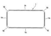
以下、本発明に係る小型電子機器用防水ガスケットを実施するための好ましい形態について、図面を参照しながら説明する。図1及び図2に示される防水ガスケット1は、図3及び図4に示される第一ケース部材2と第二ケース部材3との間に適当に圧縮された状態で介装されることにより、防水機能及び外部ダストの侵入防止機能を奏するものである。
Hereinafter, preferred embodiments for implementing a waterproof gasket for small electronic devices according to the present invention will be described with reference to the drawings. The
詳しくは、第一ケース部材2と第二ケース部材3は、外周部が互いに衝合した状態に組み立てられることによって、携帯電話機などの下部ユニットや上部ユニットの外殻ケースを構成するものである。第一ケース部材2における第二ケース部材3との対向面には、その外周に沿って、角を丸めた長方形状に延びるガスケット保持溝21が形成されている。したがって、このガスケット保持溝21に保持される防水ガスケット1もこれに対応して、図1に示されるように、ストレート部1Aと湾曲したコーナー部1Bを周方向交互に有する、角を丸めた長方形状のエンドレス形状に延びるものである。
Specifically, the
防水ガスケット1は、ゴム状弾性材料(ゴム材料又はゴム状弾性を有する合成樹脂材料)からなるものであって、ガスケット保持溝21に遊嵌可能な幅で形成され、図3及び図4に示されるように、ガスケット保持溝21の外側へ突出して第二ケース部材3に密接される断面山形のメインシール部11と、その反対側を向き、ガスケット保持溝21の底面21aに着座される内外周一対の断面円弧形の互いに平行な着座シール部12を有する。
The
防水ガスケット1における各ストレート部1Aには、図2に示されるように、メインシール部11と着座シール部12との間で幅方向両側へ張り出した内外周一対の肩部13が形成されている。この肩部13は、図3に示されるように、ガスケット保持溝21における溝肩21bと近似した高さに形成され、外側面13aが着座シール部12の外側面と略同一平面をなしている。したがって防水ガスケット1をガスケット保持溝21に保持した状態では、肩部13は溝肩21bの内側面に対して僅かな隙間をもって近接されるようになっている。
As shown in FIG. 2, each
一方、防水ガスケット1における各コーナー部1Bには、図2及び図4に示されるように、メインシール部11と着座シール部12との間で上述の肩部13より幅方向に対して相対的に後退した内外周一対の後退部14が形成されている。またこの後退部14は、メインシール部11の幅方向両側の斜面からの延長面として形成され、ストレート部1Aにおける肩部13と後退部14との境界はなだらかに形成され、言い換えれば肩部13の端部13bはコーナー部1B側へ向けて隆起高さが漸次低くなっている。このため図2に示されるように、ストレート部1Aとコーナー部1Bとの間で、防水ガスケット1の断面形状が連続的に変化している。
On the other hand, as shown in FIGS. 2 and 4, each
なお、防水ガスケット1の断面積は、第一ケース部材2におけるガスケット保持溝21の底面21aと第二ケース部材3との間で圧縮されたときの、前記ガスケット保持溝21に対する防水ガスケット1の充填率が100%を越えず、両側面がガスケット保持溝21の両内側面に可及的に接近した状態となる大きさとすることが好ましい。これは、圧縮によってガスケット保持溝21内の防水ガスケット1の充填率が100%に達すると、その時点で圧縮反力が著しく大きくなってしまうからである。
The cross-sectional area of the
上述の構成を備える小型電子機器用防水ガスケット1によれば、携帯電話機などの外殻ケースの組立過程などにおいて、ガスケット保持溝21内の防水ガスケット1にストレート部1Aを倒す方向の外力が加わった場合、このストレート部1Aは、内外周に形成された肩部13,13のうち一方が、ガスケット保持溝21における一方の溝肩21bの内側面に接触することによって支持される。このため、ストレート部1Aの倒れが抑制され、メインシール部11の所要のシール面圧が確保される。
According to the
また、ガスケット保持溝21内の防水ガスケット1にコーナー部1Bを倒す方向の外力が加わった場合、このコーナー部1Bは、円弧状に湾曲しながら90度にカーブしているため、もともと倒れにくいものとなっていることから、コーナー部1Bの倒れも小さく抑制される。
In addition, when an external force is applied to the
このため、防水ガスケット1の倒れに起因するメインシール部11のシール面圧の低下が抑制され、所要の防水性を確保することができる。また、防水ガスケット1の幅はガスケット保持溝21の幅より僅かに小さく、すなわち防水ガスケット1はガスケット保持溝21に遊嵌されるものであるため、装着の容易性も確保される。
For this reason, the fall of the seal surface pressure of the
また、この種の防水ガスケット1は、全周にわたって断面が同形同大である場合、圧縮を受けた時の反力がストレート部1Aよりもコーナー部1Bで大きくなることが知られている。しかしながら、上記構成によれば、コーナー部1Bではメインシール部11と着座シール部12との間がストレート部1Aにおける肩部13より相対的に幅方向へ後退した後退部14となっているため、その分ボリュームが小さくなり、言い換えればガスケット保持溝21内での充填率が低くなり、圧縮反力が抑制される。
Moreover, when this type of
したがって、防水ガスケット1の圧縮反力がそのコーナー部1Bで部分的に大きくなることに起因して外殻ケース(第一ケース部材2及び第二ケース部材3)に変形を生じてしまうのを防止することができる。
Therefore, it is possible to prevent the outer shell case (the
なお図5は、図3の断面形状としたストレート部と図4の断面形状としたコーナー部を圧縮したときの反力を、FEM解析した結果を示すものである。この結果から、本発明によればコーナー部の圧縮反力を有効に抑制できることが確認された。 FIG. 5 shows the result of FEM analysis of the reaction force when the straight portion having the cross-sectional shape of FIG. 3 and the corner portion having the cross-sectional shape of FIG. 4 are compressed. From this result, it was confirmed that the compression reaction force of the corner portion can be effectively suppressed according to the present invention.
1 防水ガスケット
1A ストレート部
1B コーナー部
11 メインシール部
12 着座シール部
13 肩部
14 後退部
2 第一ケース部材
21 ガスケット保持溝
21a 底面
21b 溝肩
3 第二ケース部材
DESCRIPTION OF
Claims (1)
Priority Applications (7)
| Application Number | Priority Date | Filing Date | Title |
|---|---|---|---|
| JP2009140823A JP5177690B2 (en) | 2009-06-12 | 2009-06-12 | Waterproof gasket for small electronic equipment |
| PCT/JP2010/057925 WO2010143488A1 (en) | 2009-06-12 | 2010-05-11 | Gasket for small size electronic appliance |
| EP10786019.9A EP2441987A4 (en) | 2009-06-12 | 2010-05-11 | Gasket for small size electronic appliance |
| US13/322,833 US9334962B2 (en) | 2009-06-12 | 2010-05-11 | Gasket for small size electronic appliance |
| KR1020117031051A KR101357189B1 (en) | 2009-06-12 | 2010-05-11 | Gasket for small size electronic appliance |
| CN201080025890.1A CN102803799B (en) | 2009-06-12 | 2010-05-11 | Gasket for small size electronic appliance |
| TW099115258A TW201103405A (en) | 2009-06-12 | 2010-05-13 | Gasket for small size electronic appliance |
Applications Claiming Priority (1)
| Application Number | Priority Date | Filing Date | Title |
|---|---|---|---|
| JP2009140823A JP5177690B2 (en) | 2009-06-12 | 2009-06-12 | Waterproof gasket for small electronic equipment |
Publications (2)
| Publication Number | Publication Date |
|---|---|
| JP2010286058A JP2010286058A (en) | 2010-12-24 |
| JP5177690B2 true JP5177690B2 (en) | 2013-04-03 |
Family
ID=43308748
Family Applications (1)
| Application Number | Title | Priority Date | Filing Date |
|---|---|---|---|
| JP2009140823A Active JP5177690B2 (en) | 2009-06-12 | 2009-06-12 | Waterproof gasket for small electronic equipment |
Country Status (7)
| Country | Link |
|---|---|
| US (1) | US9334962B2 (en) |
| EP (1) | EP2441987A4 (en) |
| JP (1) | JP5177690B2 (en) |
| KR (1) | KR101357189B1 (en) |
| CN (1) | CN102803799B (en) |
| TW (1) | TW201103405A (en) |
| WO (1) | WO2010143488A1 (en) |
Families Citing this family (9)
| Publication number | Priority date | Publication date | Assignee | Title |
|---|---|---|---|---|
| US20140167365A1 (en) * | 2012-12-18 | 2014-06-19 | Te-Yi Chu | Water proof sealing assembly |
| CN107889406A (en) * | 2016-09-30 | 2018-04-06 | 光宝电子(广州)有限公司 | Housing and its adhesive tape structure and the frame that blocks water |
| JP6922103B2 (en) * | 2018-11-05 | 2021-08-18 | Nok株式会社 | gasket |
| US10622027B1 (en) * | 2018-11-28 | 2020-04-14 | Western Digital Technologies, Inc. | Magnetic storage device with improved top cover gasket and associated method of manufacture |
| CN113544415B (en) * | 2019-03-14 | 2022-07-19 | 三菱电机株式会社 | Mounting structure for electrical equipment housing |
| JP7183880B2 (en) * | 2019-03-14 | 2022-12-06 | 株式会社豊田自動織機 | sealing structure |
| JP2022013151A (en) * | 2020-07-03 | 2022-01-18 | 住友電装株式会社 | Housing of electric connection box |
| GB2609415A (en) * | 2021-07-29 | 2023-02-08 | Airbus Operations Ltd | Seal |
| CN115623728A (en) * | 2022-12-14 | 2023-01-17 | 理工全盛(北京)科技有限公司 | Sealing structure and unmanned aerial vehicle detection and interference outdoor case |
Family Cites Families (14)
| Publication number | Priority date | Publication date | Assignee | Title |
|---|---|---|---|---|
| JPS58184880U (en) * | 1982-06-02 | 1983-12-08 | 日本電気株式会社 | Waterproof structure of communication equipment housing |
| JPS61165071A (en) * | 1985-01-12 | 1986-07-25 | Nissan Motor Co Ltd | Sealing structure for cover and the like |
| FR2644217A1 (en) * | 1989-03-07 | 1990-09-14 | Procal | STATIC SEAL SEAL |
| JPH11126648A (en) * | 1997-10-21 | 1999-05-11 | Yazaki Corp | Packing holding structure |
| JP3349132B2 (en) * | 1999-04-12 | 2002-11-20 | 三菱電線工業株式会社 | Low load seal |
| JP4238973B2 (en) * | 2002-05-17 | 2009-03-18 | Nok株式会社 | Rubber elastic parts |
| US6722660B2 (en) * | 2002-06-27 | 2004-04-20 | Federal-Mogul World Wide, Inc. | Molded gasket |
| JP2004076877A (en) * | 2002-08-20 | 2004-03-11 | Nok Corp | Gasket |
| CN100417847C (en) * | 2002-11-12 | 2008-09-10 | Nok株式会社 | Rubber-like elastic part |
| JP4824351B2 (en) * | 2005-06-24 | 2011-11-30 | 株式会社マーレ フィルターシステムズ | gasket |
| CN101213390B (en) * | 2005-07-07 | 2012-05-16 | Nok株式会社 | Gasket |
| JP2008249139A (en) * | 2007-03-02 | 2008-10-16 | Nok Corp | Waterproof structure of electronic equipment |
| JP4900590B2 (en) * | 2007-03-02 | 2012-03-21 | Nok株式会社 | Waterproof structure of electronic equipment |
| WO2012056768A1 (en) * | 2010-10-26 | 2012-05-03 | Nok株式会社 | Gasket |
-
2009
- 2009-06-12 JP JP2009140823A patent/JP5177690B2/en active Active
-
2010
- 2010-05-11 CN CN201080025890.1A patent/CN102803799B/en not_active Expired - Fee Related
- 2010-05-11 US US13/322,833 patent/US9334962B2/en not_active Expired - Fee Related
- 2010-05-11 EP EP10786019.9A patent/EP2441987A4/en not_active Withdrawn
- 2010-05-11 KR KR1020117031051A patent/KR101357189B1/en active IP Right Grant
- 2010-05-11 WO PCT/JP2010/057925 patent/WO2010143488A1/en active Application Filing
- 2010-05-13 TW TW099115258A patent/TW201103405A/en unknown
Also Published As
| Publication number | Publication date |
|---|---|
| WO2010143488A1 (en) | 2010-12-16 |
| US20120074653A1 (en) | 2012-03-29 |
| CN102803799B (en) | 2014-11-19 |
| TW201103405A (en) | 2011-01-16 |
| EP2441987A4 (en) | 2016-05-18 |
| CN102803799A (en) | 2012-11-28 |
| EP2441987A1 (en) | 2012-04-18 |
| KR20120018809A (en) | 2012-03-05 |
| US9334962B2 (en) | 2016-05-10 |
| KR101357189B1 (en) | 2014-01-29 |
| JP2010286058A (en) | 2010-12-24 |
Similar Documents
| Publication | Publication Date | Title |
|---|---|---|
| JP5177690B2 (en) | Waterproof gasket for small electronic equipment | |
| KR101682068B1 (en) | Water-proof structure for opening of case of appliance | |
| JP5081004B2 (en) | gasket | |
| WO2016006393A1 (en) | Gasket | |
| US20120043331A1 (en) | Water-proof structure for opening of case of appliance | |
| JP2010124072A (en) | Waterproofing mechanism for housing, assembling method for housing, and mobile terminal unit | |
| WO2007007611A1 (en) | Gasket | |
| JP2008249139A (en) | Waterproof structure of electronic equipment | |
| WO2013153715A1 (en) | Gasket | |
| JP4987243B2 (en) | Seal structure | |
| JP6017282B2 (en) | Sealing structure | |
| JP6180713B2 (en) | Waterproof structure of the opening / closing part of the equipment case | |
| JP5081679B2 (en) | Waterproof seal structure and equipment provided with this seal structure | |
| JP4128802B2 (en) | Plasma resistant seal | |
| JP5373160B2 (en) | Waterproof seal structure and equipment provided with this seal structure | |
| JP2009257459A (en) | Gasket | |
| JP6022891B2 (en) | Film-integrated waterproof packing | |
| JP5449105B2 (en) | Battery compartment cover and electronic device | |
| JP2013055249A (en) | Waterproof structure, portable device including waterproof structure, and manufacturing method of portable device | |
| JP5318264B2 (en) | Equipment with seal structure | |
| JP5672908B2 (en) | gasket | |
| JP2023016544A (en) | gasket | |
| JP2008227031A (en) | Waterproof structure for electronic equipment | |
| JP6122176B1 (en) | Waterproof case device | |
| JP2021116830A (en) | Sealing device |
Legal Events
| Date | Code | Title | Description |
|---|---|---|---|
| A711 | Notification of change in applicant |
Free format text: JAPANESE INTERMEDIATE CODE: A711 Effective date: 20110714 |
|
| A621 | Written request for application examination |
Free format text: JAPANESE INTERMEDIATE CODE: A621 Effective date: 20120216 |
|
| TRDD | Decision of grant or rejection written | ||
| A01 | Written decision to grant a patent or to grant a registration (utility model) |
Free format text: JAPANESE INTERMEDIATE CODE: A01 Effective date: 20121128 |
|
| A61 | First payment of annual fees (during grant procedure) |
Free format text: JAPANESE INTERMEDIATE CODE: A61 Effective date: 20121227 |
|
| R150 | Certificate of patent or registration of utility model |
Ref document number: 5177690 Country of ref document: JP Free format text: JAPANESE INTERMEDIATE CODE: R150 |
|
| R250 | Receipt of annual fees |
Free format text: JAPANESE INTERMEDIATE CODE: R250 |
|
| R250 | Receipt of annual fees |
Free format text: JAPANESE INTERMEDIATE CODE: R250 |
|
| R250 | Receipt of annual fees |
Free format text: JAPANESE INTERMEDIATE CODE: R250 |
|
| R250 | Receipt of annual fees |
Free format text: JAPANESE INTERMEDIATE CODE: R250 |
|
| R250 | Receipt of annual fees |
Free format text: JAPANESE INTERMEDIATE CODE: R250 |
|
| R250 | Receipt of annual fees |
Free format text: JAPANESE INTERMEDIATE CODE: R250 |
|
| R250 | Receipt of annual fees |
Free format text: JAPANESE INTERMEDIATE CODE: R250 |
|
| R250 | Receipt of annual fees |
Free format text: JAPANESE INTERMEDIATE CODE: R250 |
|
| R250 | Receipt of annual fees |
Free format text: JAPANESE INTERMEDIATE CODE: R250 |