JP2021531968A - Fluid tip for spray coating equipment - Google Patents
Fluid tip for spray coating equipment Download PDFInfo
- Publication number
- JP2021531968A JP2021531968A JP2021506529A JP2021506529A JP2021531968A JP 2021531968 A JP2021531968 A JP 2021531968A JP 2021506529 A JP2021506529 A JP 2021506529A JP 2021506529 A JP2021506529 A JP 2021506529A JP 2021531968 A JP2021531968 A JP 2021531968A
- Authority
- JP
- Japan
- Prior art keywords
- fluid
- bell cup
- chip
- outlet port
- tip
- Prior art date
- Legal status (The legal status is an assumption and is not a legal conclusion. Google has not performed a legal analysis and makes no representation as to the accuracy of the status listed.)
- Granted
Links
Images

Classifications
-
- B—PERFORMING OPERATIONS; TRANSPORTING
- B05—SPRAYING OR ATOMISING IN GENERAL; APPLYING FLUENT MATERIALS TO SURFACES, IN GENERAL
- B05B—SPRAYING APPARATUS; ATOMISING APPARATUS; NOZZLES
- B05B15/00—Details of spraying plant or spraying apparatus not otherwise provided for; Accessories
- B05B15/14—Arrangements for preventing or controlling structural damage to spraying apparatus or its outlets, e.g. for breaking at desired places; Arrangements for handling or replacing damaged parts
- B05B15/18—Arrangements for preventing or controlling structural damage to spraying apparatus or its outlets, e.g. for breaking at desired places; Arrangements for handling or replacing damaged parts for improving resistance to wear, e.g. inserts or coatings; for indicating wear; for handling or replacing worn parts
-
- B—PERFORMING OPERATIONS; TRANSPORTING
- B05—SPRAYING OR ATOMISING IN GENERAL; APPLYING FLUENT MATERIALS TO SURFACES, IN GENERAL
- B05B—SPRAYING APPARATUS; ATOMISING APPARATUS; NOZZLES
- B05B15/00—Details of spraying plant or spraying apparatus not otherwise provided for; Accessories
- B05B15/50—Arrangements for cleaning; Arrangements for preventing deposits, drying-out or blockage; Arrangements for detecting improper discharge caused by the presence of foreign matter
- B05B15/55—Arrangements for cleaning; Arrangements for preventing deposits, drying-out or blockage; Arrangements for detecting improper discharge caused by the presence of foreign matter using cleaning fluids
-
- B—PERFORMING OPERATIONS; TRANSPORTING
- B05—SPRAYING OR ATOMISING IN GENERAL; APPLYING FLUENT MATERIALS TO SURFACES, IN GENERAL
- B05B—SPRAYING APPARATUS; ATOMISING APPARATUS; NOZZLES
- B05B3/00—Spraying or sprinkling apparatus with moving outlet elements or moving deflecting elements
- B05B3/02—Spraying or sprinkling apparatus with moving outlet elements or moving deflecting elements with rotating elements
- B05B3/08—Spraying or sprinkling apparatus with moving outlet elements or moving deflecting elements with rotating elements in association with stationary outlet or deflecting elements
- B05B3/082—Spraying or sprinkling apparatus with moving outlet elements or moving deflecting elements with rotating elements in association with stationary outlet or deflecting elements the spraying being effected by centrifugal forces
-
- B—PERFORMING OPERATIONS; TRANSPORTING
- B05—SPRAYING OR ATOMISING IN GENERAL; APPLYING FLUENT MATERIALS TO SURFACES, IN GENERAL
- B05B—SPRAYING APPARATUS; ATOMISING APPARATUS; NOZZLES
- B05B3/00—Spraying or sprinkling apparatus with moving outlet elements or moving deflecting elements
- B05B3/02—Spraying or sprinkling apparatus with moving outlet elements or moving deflecting elements with rotating elements
- B05B3/10—Spraying or sprinkling apparatus with moving outlet elements or moving deflecting elements with rotating elements discharging over substantially the whole periphery of the rotating member
- B05B3/1007—Spraying or sprinkling apparatus with moving outlet elements or moving deflecting elements with rotating elements discharging over substantially the whole periphery of the rotating member characterised by the rotating member
- B05B3/1014—Spraying or sprinkling apparatus with moving outlet elements or moving deflecting elements with rotating elements discharging over substantially the whole periphery of the rotating member characterised by the rotating member with a spraying edge, e.g. like a cup or a bell
-
- B—PERFORMING OPERATIONS; TRANSPORTING
- B05—SPRAYING OR ATOMISING IN GENERAL; APPLYING FLUENT MATERIALS TO SURFACES, IN GENERAL
- B05B—SPRAYING APPARATUS; ATOMISING APPARATUS; NOZZLES
- B05B3/00—Spraying or sprinkling apparatus with moving outlet elements or moving deflecting elements
- B05B3/02—Spraying or sprinkling apparatus with moving outlet elements or moving deflecting elements with rotating elements
- B05B3/10—Spraying or sprinkling apparatus with moving outlet elements or moving deflecting elements with rotating elements discharging over substantially the whole periphery of the rotating member
- B05B3/1064—Spraying or sprinkling apparatus with moving outlet elements or moving deflecting elements with rotating elements discharging over substantially the whole periphery of the rotating member the liquid or other fluent material to be sprayed being axially supplied to the rotating member through a hollow rotating shaft
-
- B—PERFORMING OPERATIONS; TRANSPORTING
- B05—SPRAYING OR ATOMISING IN GENERAL; APPLYING FLUENT MATERIALS TO SURFACES, IN GENERAL
- B05B—SPRAYING APPARATUS; ATOMISING APPARATUS; NOZZLES
- B05B5/00—Electrostatic spraying apparatus; Spraying apparatus with means for charging the spray electrically; Apparatus for spraying liquids or other fluent materials by other electric means
- B05B5/025—Discharge apparatus, e.g. electrostatic spray guns
- B05B5/04—Discharge apparatus, e.g. electrostatic spray guns characterised by having rotary outlet or deflecting elements, i.e. spraying being also effected by centrifugal forces
- B05B5/0403—Discharge apparatus, e.g. electrostatic spray guns characterised by having rotary outlet or deflecting elements, i.e. spraying being also effected by centrifugal forces characterised by the rotating member
- B05B5/0407—Discharge apparatus, e.g. electrostatic spray guns characterised by having rotary outlet or deflecting elements, i.e. spraying being also effected by centrifugal forces characterised by the rotating member with a spraying edge, e.g. like a cup or a bell
Landscapes
- Nozzles (AREA)
- Application Of Or Painting With Fluid Materials (AREA)
- Electrostatic Spraying Apparatus (AREA)
Abstract
噴霧システムは、ターゲットに流体を塗布するように構成された噴霧塗布装置(12)を含む。噴霧システムはまた、噴霧塗布装置(12)の回転ベルカップ(44)と、回転ベルカップ(44)に連結された噴霧塗布装置(12)のスプラッシュプレート(42)と、噴霧塗布装置(12)の流体チップ(40)とを含む。流体チップ(40)は、流体を回転ベルカップ(44)上に出力するように構成される。流体チップ(40)は、流体チップ(40)の長手方向流体チップ軸(72)に沿って延在する流体チップ通路(39)を含む。長手方向流体チップ軸(72)は、噴霧塗布装置(12)のスプラッシュプレート(42)と交差する。また、流体チップ(40)は、流体チップ通路(39)から回転ベルカップ(44)上に流体を出力するように構成された流体出口ポート(75)を含む。流体出口ポート(75)は、流体チップ(40)の長手方向流体チップ軸(72)に対してある角度で配置された流体出口軸(76)に沿って延在する。The spray system includes a spray application device (12) configured to apply a fluid to the target. The spray system also includes a rotary bell cup (44) of the spray coater (12), a splash plate (42) of the spray coater (12) connected to the rotary bell cup (44), and a spray coater (12). Includes the fluid chip (40) of. The fluid tip (40) is configured to output the fluid onto the rotating bell cup (44). The fluid tip (40) includes a fluid tip passage (39) extending along the longitudinal fluid tip axis (72) of the fluid tip (40). The longitudinal fluid tip shaft (72) intersects the splash plate (42) of the spray coating device (12). The fluid tip (40) also includes a fluid outlet port (75) configured to output fluid from the fluid tip passage (39) onto the rotating bell cup (44). The fluid outlet port (75) extends along the fluid outlet axis (76) located at an angle to the longitudinal fluid tip axis (72) of the fluid chip (40).
Description
関連出願の相互参照
この出願は、2018年8月7日出願の米国仮特許出願第62/715,656号、発明の名称「FLUID TIP FOR SPRAY APPLICATOR(噴霧塗布装置用流体チップ)」に基づく優先権及び利益を主張するものであり、その全体が参照により本明細書に組み込まれる。
Cross-reference of related applications This application is prioritized based on US Provisional Patent Application No. 62 / 715,656 filed on August 7, 2018, the title of the invention "FLUID TIP FOR SPRAY APPLICATOR". It asserts rights and interests and is incorporated herein by reference in its entirety.
本明細書に開示される主題は、概して噴霧塗布装置に関し、より詳細には、噴霧塗布装置用流体チップに関する。 The subject matter disclosed herein generally relates to a spray coating device, and more particularly to a fluid tip for a spray coating device.
スプレーガンなどの噴霧塗布装置は、スプレーコーティングを多種多様な対象物体に塗布するために使用されてもよい。流体は、噴霧塗布装置を通って流れ、噴霧塗布装置の流体チップから出てもよい。噴霧塗布装置から出る流体のより均一な分布を達成するために、スプラッシュプレート及び回転ベルカップが典型的に使用される。流体チップを出る流体は、スプラッシュプレートに接触し、回転ベルカップの表面積にわたって分散される。次いで、流体は、目標物に向かって噴霧塗布装置から出る。残念ながら、流体が接触し、スプラッシュプレートによって分配されると、スプラッシュプレートは、摩耗および劣化を経験する可能性があり、これは、噴霧塗布装置のメンテナンスに関連するコストの増加につながる可能性がある。 A spray coating device, such as a spray gun, may be used to apply the spray coating to a wide variety of objects. The fluid may flow through the spray coating device and exit the fluid tip of the spray coating device. Splash plates and rotating bell cups are typically used to achieve a more uniform distribution of fluid exiting the spray coating device. The fluid leaving the fluid tip contacts the splash plate and is dispersed over the surface area of the rotating bell cup. The fluid then exits the spray coating device towards the target. Unfortunately, when the fluid comes into contact and is distributed by the splash plate, the splash plate can experience wear and deterioration, which can lead to increased costs associated with the maintenance of the spray coating equipment. be.
当初の請求された主題と技術的範囲に見合った特定の実施態様を以下に要約する。これらの実施態様は、請求された主題の技術的範囲を限定することを意図するものではなく、むしろこれらの実施態様は、開示された主題の可能な形態の簡潔な要約を提供することのみを意図するものである。実際、開示される実施形態は、以下に記載される実施形態と類似または異なってもよい様々な形態を包含してもよい。 Specific embodiments commensurate with the originally requested subject matter and technical scope are summarized below. These embodiments are not intended to limit the technical scope of the claimed subject matter, but rather these embodiments merely provide a concise summary of possible forms of the disclosed subject matter. It is intended. In fact, the disclosed embodiments may include various embodiments that may be similar or different from the embodiments described below.
一実施形態では、噴霧システムは、ターゲットに流体を塗布するように構成された噴霧塗布装置を含む。噴霧システムはまた、噴霧塗布装置の回転ベルカップと、回転ベルカップに連結された噴霧塗布装置のスプラッシュプレートと、噴霧塗布装置の流体チップとを含む。流体チップは、流体を回転ベルカップ上に出力するように構成される。流体チップは、流体チップの長手方向流体チップ軸に沿って延在する流体チップ通路を含む。長手方向流体チップ軸は、噴霧塗布装置のスプラッシュプレートと交差する。また、流体チップは、流体チップ通路から回転ベルカップ上に流体を出力するように構成された流体出口ポートを含む。流体出口ポートは、流体チップの長手方向流体チップ軸に対してある角度で(at an angle)配置された流体出口軸に沿って延在する。 In one embodiment, the spray system comprises a spray application device configured to apply a fluid to the target. The spray system also includes a rotating bell cup of the spray coating device, a splash plate of the spray coating device connected to the rotating bell cup, and a fluid tip of the spray coating device. The fluid tip is configured to output the fluid onto a rotating bell cup. The fluid chip includes a fluid chip passage that extends along the longitudinal fluid chip axis of the fluid chip. The longitudinal fluid tip axis intersects the splash plate of the spray coating device. The fluid tip also includes a fluid outlet port configured to output fluid from the fluid tip passage onto a rotating bell cup. The fluid outlet port extends along the fluid outlet axis arranged at an angle with respect to the longitudinal fluid chip axis of the fluid chip.
別の実施形態では、噴霧システムは、噴霧塗布装置の流体チップを含む。流体チップは、噴霧塗布装置の回転ベルカップ上に流体を出力するように構成される。流体チップは、流体チップの長手方向流体チップ軸に沿って延在する流体チップ通路と、流体を回転ベルカップ上に出力するように構成された流体出口ポートとを含む。流体出口ポートは、流体チップの長手方向流体チップ軸に対してある角度で配置された流体出口軸を含む。 In another embodiment, the spray system comprises a fluid chip of a spray coating device. The fluid tip is configured to output the fluid onto the rotating bell cup of the spray coating device. The fluid chip includes a fluid chip passage extending along the longitudinal fluid chip axis of the fluid chip and a fluid outlet port configured to output the fluid onto a rotating bell cup. The fluid outlet port includes a fluid outlet axis located at an angle to the longitudinal fluid chip axis of the fluid chip.
さらなる実施形態では、噴霧システムを作動させる方法は、噴霧塗布装置の流体チップの流体チップ通路に沿って流体を流すステップを含み、流体チップ通路は、流体チップの長手方向流体チップ軸に沿って延在する。本方法は、さらに、流体出口ポートを通して流体を流体出口軸に沿って導くステップを含み、流体出口ポートは、流体チップ通路に流体的に連結され、流体出口軸は、長手方向流体チップ軸に対してある角度で配置される。本方法はまた、流体出口ポートから流体を回転ベルカップのベルカップ面上に堆積させるステップを含む。 In a further embodiment, the method of activating the spray system comprises flowing fluid along the fluid tip passage of the fluid tip of the spray applicator, the fluid tip passage extending along the longitudinal fluid tip axis of the fluid chip. There is. The method further comprises guiding the fluid along the fluid outlet axis through the fluid outlet port, the fluid outlet port being fluidly coupled to the fluid chip passage, and the fluid outlet axis relative to the longitudinal fluid chip axis. Arranged at a certain angle. The method also comprises depositing fluid from the fluid outlet port onto the bell cup surface of the rotating bell cup.
本開示のこれらおよび他の特徴、態様、および利点は、以下の詳細な説明を、類似の符号が図面全体を通して類似の部品を表す添付図面を参照して読み取ると、より良く理解される。 These and other features, embodiments, and advantages of the present disclosure are better understood by reading the following detailed description with reference to the accompanying drawings in which similar reference numerals represent similar parts throughout the drawing.
本開示の1つ以上の具体的な実施形態について、以下に説明する。これらの説明される実施態様は、本開示の例示に過ぎない。加えて、これらの例示的実施形態の簡潔な説明を提供するための努力において、実際の実施形態の全ての特徴は、明細書に記載されない場合がある。全てのそのような実際の実施例の開発において、全ての技術または設計の計画におけるのと同様に、システム関連の制約、またはビジネス関連の制約へ追従することなどの開発者に特有の目標を成し遂げるために、多くの実施例特有の決定がなされなければならず、これは実施例によって異なってもよいことが認識されるであろう。更に、この種の開発作業は複雑かつ時間がかかるものでありうるが、本開示の利益を受ける当業者にとって、設計、作製および製造の日常的な作業であるということが理解されるであろう。 One or more specific embodiments of the present disclosure will be described below. These described embodiments are merely exemplary of the present disclosure. In addition, in an effort to provide a brief description of these exemplary embodiments, all features of the actual embodiments may not be described in the specification. In the development of all such real-world examples, as in all technology or design plans, achieve developer-specific goals such as following system-related or business-related constraints. It will be appreciated that many embodiment-specific decisions must be made in order to this, which may vary from embodiment to embodiment. Moreover, although this type of development work can be complex and time consuming, it will be appreciated by those skilled in the art who will benefit from the present disclosure that it is a routine design, fabrication and manufacturing task. ..
本開示の様々な実施形態の要素を導入する場合、冠詞「a」、「an」、「the」および「the」は、要素のうちの1つまたは複数が存在することを意味することを意図しており、「含む」、および「有する」という用語は、包含を意図しており、記載された要素以外に追加の要素が存在し得ることを意味する。 When introducing the elements of the various embodiments of the present disclosure, the articles "a", "an", "the" and "the" are intended to mean that one or more of the elements are present. And the terms "include" and "have" are intended to include and mean that additional elements may exist in addition to the elements described.
本開示の実施形態は、流体または空気−流体混合物を流体チップから噴霧塗布装置の回転ベルカップに向けるように構成された噴霧塗布装置の流体チップに向けられる。噴霧塗布装置は、ハンドヘルド手動スプレーガン、自動スプレーユニット(例えば、ロボットに取り付けられたスプレーユニット)、スプレーブースに取り付けられたスプレーユニット、又は任意の他の適当なスプレー装置とすることができる。噴霧塗布装置は、気体(例えば、空気)を使用して液体の微粒化を助ける、液体の噴霧を形状、噴霧器のバルブを作動させる、またはこれらの組み合わせを使用する、空気駆動型噴霧装置を含んでもよい。噴霧塗布装置は、回転ベルカップを含んでもよく、回転して噴霧を生成するのを助ける。例えば、回転ベルカップは、毎分10,000回転(rpm)から100,000rpmの範囲の速度で回転することができる。いくつかの実施形態では、流体チップは、回転ベルカップが回転するときに、噴霧塗布装置の本体に対して静止したままでよい。噴霧塗布装置は、静電スプレー装置を含んでもよく、静電スプレー装置は、電場を生成して、目標物体上にスプレーを引きつけるのを助ける。さらに、噴霧塗布装置は、物体の表面上にコーティングを生成するための塗料のようなコーティング材料の噴霧を生成するように構成された噴霧コーティング装置であってもよい。流体源は、流体導管、流体容器(例えば、重力供給流体容器、サイフォン供給流体容器、多流体供給容器、加圧流体容器など)、またはそれらの任意の組合せを含んでもよい。流体チップは、流体導管を出る流体または空気−流体混合物を回転ベルカップに向かって導き、噴霧塗布装置のスプラッシュプレートから離れる(すなわち、直接ではない)ように導くために使用されてもよい。特に、流体チップは、スプラッシュプレートに対してある角度で配置された1つまたは複数のポートを含み、流体または空気−流体混合物が、スプラッシュプレートから離れ、かつ回転ベルカップに向かって流体チップをある角度で出るようにしてもよい。 The embodiments of the present disclosure are directed to a fluid tip of a spray coating device configured to direct a fluid or air-fluid mixture from the fluid tip to the rotating bell cup of the spray coating device. The spray application device can be a handheld manual spray gun, an automatic spray unit (eg, a spray unit mounted on a robot), a spray unit mounted on a spray booth, or any other suitable spray device. Spray application devices include air-driven spray devices that use gases (eg, air) to help atomize the liquid, shape the spray of the liquid, activate the valves of the sprayer, or use a combination of these. But it may be. The spray coating device may include a rotating bell cup to help rotate to generate a spray. For example, a rotating bell cup can rotate at a speed in the range of 10,000 rpm (rpm) to 100,000 rpm. In some embodiments, the fluid tip may remain stationary with respect to the body of the spray coating device as the rotating bell cup rotates. The spray coating device may include an electrostatic spray device, which helps generate an electric field to attract the spray onto the target object. Further, the spray coating device may be a spray coating device configured to generate a spray of a coating material such as a paint for forming a coating on the surface of an object. The fluid source may include a fluid conduit, a fluid vessel (eg, a gravity feed fluid vessel, a siphon feed fluid vessel, a multi-fluid supply vessel, a pressurized fluid vessel, etc.), or any combination thereof. The fluid tip may be used to guide the fluid or air-fluid mixture leaving the fluid conduit towards the rotating bell cup and away from (ie, not directly) the splash plate of the spray coating device. In particular, the fluid tip comprises one or more ports located at an angle to the splash plate, the fluid or air-fluid mixture is away from the splash plate and has the fluid tip towards the rotating bell cup. You may make it come out at an angle.
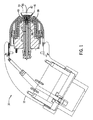
図面を参照すると、図1は、塗料(塗料、インク、ワニスなど)を噴霧するための噴霧塗布装置12を含む、噴霧システム10の実施形態の側面図である。噴霧塗布装置12は、コーティング材料をスプレーするのに適した任意のスプレーコーティング装置(例えば、重力供給、サイフォン、高容量の低圧、又は圧力)であってよい。噴霧塗布装置12は、噴霧材料の塗布を可能にするために流体通路を提供するように構成された様々な構成要素を含んでもよい。図示の実施形態では、噴霧塗布装置12は、噴霧塗布装置12を通って被覆材料で被覆されるターゲットに向かって移動するために、被覆材料のための流体通路を提供するように構成された流体管14と流体チップ40とを含む。流体チップ40は、流体管14及び/又は噴霧塗布装置12の他の構成要素に取り外し可能に且つ流体的に連結することができる。例えば、流体チップ40および流体管14は、流体チップ40が流体管14にねじ込まれ得るように、ねじ込まれ得る。
Referring to the drawings, FIG. 1 is a side view of an embodiment of the
流体管14は、流体通路16を含んでもよい。流体管14および流体チップ40はまた、他の種類の通路を含んでもよい。作動中、流体管14の流体通路16を通る空気および流体(例えば、コーティング材料)の流れを作動させるために、トリガーまたは他の適切な制御を使用してもよい。特定の実施形態において、噴霧塗布装置12は、他の手段(例えば、ロボットコントローラ、遠隔等)を介して制御されてもよい。特定の実施形態において、流体は、流体通路16に入る前に、空気または別の流体と混合してもよい。空気と流体とが混合して、流体通路16内に空気−流体混合体を作り出すことができる。流体通路16は、流体管14から流体チップ40内および/またはそれを通って延在してもよい。例えば、ある実施形態では、流体通路16は、流体管14の流体管通路38と、流体チップ40が噴霧塗布装置12に結合されたときに、流体管通路38と流体チップ通路39が流体通路16を形成するように、流体チップ40の流体チップ通路39とを含んでもよい。いくつかの実施態様において、噴霧塗布装置12は、噴霧塗布装置12を通って流体を流すように構成された追加の流体通路を含んでもよい。
The
特定の実施形態において、流体通路16は、流体および/または空気−流体混合物を流すように構成されてもよい。そのように、噴霧塗布装置12は、流体及び/又は空気−流体混合物を流動させて塗布するように構成することができる。例えば、噴霧システム10は、噴霧システム10の空気通路および流体通路にそれぞれ空気および流体を受け入れるための空気入口および流体注入口を含んでもよい。空気入口(例えば、ポート)及び流体注入口(例えば、ポート)は、空気源及び流体源のような噴霧システム10の1つ以上の噴霧成分に連結することができる。例えば、空気入口は、圧縮空気又は空気リザーバ(例えば、空気タンク)に連結することができる。空気入口は、種々の接続を用いて空気源に結合することができる。例えば、空気入口は、第1のコネクタ(例えば、オスコネクタ)を含んでもよく、空気源は、対応する第2のコネクタ(例えば、メスコネクタ)を含んでもよい。いくつかの実施態様において、空気入口は、雌型コネクタであってもよく、空気源は、雄型コネクタであってもよい。同様に、流体注入口は、流体リザーバ(例えば、使い捨てカップ、流体圧力容器)または種々の接続を使用する別の流体源などの流体源(例えば、塗料ミキサー、圧力ポット、ギアポンプなど)に結合してもよい。例えば、流体注入口は、流体源の対応するオスコネクタまたはメスコネクタに結合するオスコネクタまたはメスコネクタを含んでもよい。
In certain embodiments, the
噴霧塗布装置12は、流体チップ40内に延びることができる流体通路16を通って流体又は空気−流体混合物を流動させるように構成されている。上述したように、流体管通路38および流体チップ通路39は、流体通路16を形成することができる。流体チップ40は、噴霧塗布装置12の端部に配置することができ、噴霧塗布装置12の回転ベルカップ44に流体または空気−流体混合物を送達するように構成することができる。噴霧塗布装置12はまた、回転ベルカップ44に連結されたスプラッシュプレート42を含んでもよい。従来の実施形態では、スプラッシュプレートは、流体チップを出て回転ベルカップ上に流体または空気−流体混合物を分配するように構成されてもよい。換言すれば、伝統的な噴霧塗布装置は、流体または流体チップを出る空気−流体混合物の流れを方向転換し、流体の流れを回転ベルカップに向けるように構成されたスプラッシュプレートを含んでもよい。しかしながら、本実施形態では、かつ以下により詳細に説明するように、流体または空気−流体混合物は、流体通路16を通って流れ、回転ベルカップ44に向かって、かつスプラッシュプレート42から離れる、ある角度で流体チップ40を出るように構成されている。
The
噴霧塗布装置12が流体チップ40から回転ベルカップ44上に流体または空気−流体混合物を直接分配するように構成されている間、スプラッシュプレート42は依然として噴霧塗布装置12に含まれていてもよい。スプラッシュプレート42は、噴霧塗布装置12が流体チップ40から回転ベルカップ44上への流体流を破壊することができる環境からの空気を遮断するように構成することができる。例えば、回転ベルカップ44が回転し、流体または空気−流体混合物が回転ベルカップ44から出ると、回転ベルカップ44のベルカップ領域45内に負圧が作られ得る。環境からの空気は、負圧のためにベルカップ領域45に入り得る。スプラッシュプレート42がないと、ベルカップ領域45に流入する空気は、流体チップ領域41に入り、流体チップ40から回転ベルカップ44への流体または空気−流体混合物の流れを乱す可能性がある。そのように、スプラッシュプレート42は、環境からの空気を遮断することによって、回転ベルカップ44上への流体または空気−流体混合物の流れを補助するように構成することができる。
The
噴霧塗布装置12の種々の構成要素は、メンテナンスのため等の種々の理由により、運転中に交換可能である。例えば、流体管14、流体チップ40、スプラッシュプレート42、および回転ベルカップ44は、他の構成要素の中でも、新品または異なる構成要素と交換することができる。加えて、噴霧塗布装置12の種々の構成要素は、種々の材料又は材料の組合せで形成することができる。図示の実施形態では、流体管14および流体チップ40は、ステンレス鋼および/または他の材料であってもよい。スプラッシュプレート42は、複合プラスチック、硬化ステンレス鋼、チタン、および/または他の材料であってもよく、コーティング(例えば、ダイヤモンド状コーティング(DLC))で被覆されてもよく、またはめっきされてもよい。更に、回転ベルカップ44は、複合プラスチック、ステンレス鋼、及び/又は他の材料であってもよい。しかし、流体管14、流体チップ40、スプラッシュプレート42、および回転ベルカップ44を形成するために、他の適切な材料を使用してもよいことが理解されよう。
The various components of the
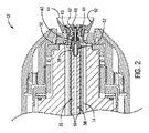
図2は、図1の噴霧システム10の噴霧塗布装置12の部分断面側面図であり、噴霧塗布装置12の流体チップ40の一実施形態を示す。上述したように、噴霧塗布装置12は、流体管14、流体チップ40、スプラッシュプレート42、および/または回転ベルカップ44を含んでもよい。スプラッシュプレート42は、接続部43を介して回転ベルカップ44に連結することができる。接続部43は、締結具(例えば、ねじ、ボルト、リベット等)であってもよい。さらに、2つの接続部(すなわち、接続部43)が図2に示されているが、噴霧塗布装置12のいくつかの実施形態は、スプラッシュプレート42と回転ベルカップ44との間の単一接続部、3つの接続部、又は3つ以上の接続部を含んでもよい。特定の実施形態では、スプラッシュプレート42は、回転ベルカップ44の一体構成要素であってもよいし、逆の構成要素であってもよい。
FIG. 2 is a partial cross-sectional side view of the
流体管14および流体チップ40は、それぞれ、図示の実施形態において流体通路16を形成する流体管通路38および流体チップ通路39を含んでもよい。本明細書に記載されるように、流体または空気−流体混合物が、流体通路16を通って流れてもよい。流体通路16及び流体チップ通路39は、流体チップ40の端部48でスプラッシュプレート42に隣接して終端することができる。また、流体チップ40は、ねじ式接続部52または他の適切な接続部を介して流体管14に結合されてもよい。ねじ式接続部52は、流体管14および流体チップ40の両方に、互いに係合するねじを含み、流体チップ40が流体管14にねじ込まれるように、またはその上にねじ込まれるように構成されてもよい。いくつかの実施態様において、流体管14および流体チップ40は、ねじ式接続部52に加えて、またはその代わりに、他の機構または特徴によって結合されてもよい。さらに、噴霧塗布装置12は、流体管14および流体チップ40を通って延びる流体通路16が確実にシールされるように、ねじ式接続部52に隣接して配置されたシール機構を含んでもよい。例えば、噴霧塗布装置12は、流体通路16が確実にシールされるように、ねじ式接続部52に隣接して配置された1つまたは複数のOリングを含むことができる。
The
ベルカップ44は、ベルカップ面92を含むことができる。ベルカップ面92は、流体チップ40から出る流体がベルカップ44に沿って流れて出ることを可能にすることができる。図示するように、ベルカップ面92は、ベルカップ44のほぼ湾曲した縁部である。特定の実施形態において、ベルカップ面92は、湾曲部分に加えて直線部分を含んでもよい。更に、ベルカップ面92のある部分又は部分は、互いに対して角度をなして配置することができる。
The
特定の実施形態では、流体チップ40はまた、1つ以上の流体チップ溶媒通路50を含み得る。図示のように、流体チップ溶媒通路50は、流体チップ通路39に隣接するが、これとは別個の流体チップ40を通って延びる。流体チップ溶媒通路50は、噴霧塗布装置12を通って延びる環状流体管溶媒通路51に流体的に連結されてもよい。環状流体管溶媒通路51は、溶媒を流体チップ溶媒通路50に送達するために、流体管14の長さの一部を下って溶媒を流すように構成されてもよい。以下でより詳細に説明するように、流体チップ40は、噴霧塗布装置12の構成要素に溶媒を送達するように構成された二次溶媒通路を含むことができる。
In certain embodiments, the
流体チップ溶媒通路50は、溶媒を流体チップ40の端部48に、スプラッシュプレート42に、および/または回転ベルカップ44に送達するように構成される。いくつかの実施態様において、流体チップ40を出る流体は、流体チップ40、スプラッシュプレート42、および回転ベルカップ44に付着してもよい。流体チップ40に送達された溶媒は、スプラッシュプレート42に、および/または回転ベルカップ44に送達され、噴霧塗布装置12のこれらの構成要素を除去/除去するように構成されてもよい。
The fluid chip
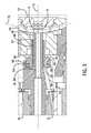
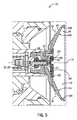
図3は、図1の噴霧システム10の噴霧塗布装置12の部分断面側面図であり、噴霧塗布装置12の流体チップ40の一実施形態を示す。上述のように、流体チップ40は、流体チップ通路39および流体チップ溶媒通路50を含むことができる。流体または空気−流体混合物は、長手方向流体チップ軸72に沿って流体チップ通路39(すなわち、流体通路16を通って)を流れ、流体出口軸76に沿って流体出口ポート75で流体チップ40を出ることができる。流体チップ通路39は、流体出口ポート75に流体的に連結されてもよい。図示のように、長手方向流体チップ軸72も、スプラッシュプレート42と交差する。このようにして、流体チップ40の流体出口ポート75を出る流体または空気−流体混合物が、スプラッシュプレート42の代わりに回転ベルカップ44の方へ向けられる。その結果、スプレー塗布装置12によって塗布されるより少ない流体(例えば、コーティング材料)がスプラッシュプレート42の方へ向けられ、スプラッシュプレート42の摩耗及び劣化を減少させる可能性がある。いくつかの実施態様において、流体チップ40の流体出口ポートは、スプラッシュプレート42に部分的に向かう角度(すなわち、長手方向流体チップ軸72に対してある角度)で配置されてもよく、一方、以下の図5〜7を参照して説明されるように、流体チップ40からスプラッシュプレート42への流体または空気−流体混合物の直接的塗布を依然として低減する。
FIG. 3 is a partial cross-sectional side view of the
流体出口ポート75は、サイズを変更することができる。例えば、流体出口ポート75は、いくつかの実施態様において、直径0.7ミリメートル(mm)から1.62mmの範囲であり得る。さらに、特定の用途のために選択された流体出口ポート75の直径は、流体の粘度、または流体出口ポート75を出る空気−流体混合物に依存し得る。例えば、噴霧塗布装置12が、より低い粘度(すなわち、より薄い流体)を有する流体または空気−流体混合物と共に使用される実施形態では、流体出口ポート75は、より小さい直径を有してもよい。対照的に、噴霧塗布装置12が、より高い粘度(すなわち、より厚い流体)を有する流体または空気−流体混合物とともに使用される実施形態では、流体出口ポート75は、より大きな直径を有してもよい。加えて、本明細書に記載される他の実施形態の流体出口ポート75は、同様の直径および特性を有してもよい。いくつかの実施態様において、流体出口ポート75の直径は一定であるが、流体チップ40の他の実施態様は、様々な直径寸法の流体出口ポート75を含んでもよい。
The
流体チップ溶媒通路50は、種々のポートを介して流体チップ40から溶媒を分配するように構成された二次溶媒通路に連結されてもよい。図示の実施形態では、流体チップ溶媒通路50は、一次環状溶媒通路54を介して、二次半径方向溶媒通路60および二次環状溶媒通路62に連結されている。一次環状溶媒通路54は、流体チップ通路39を囲んでもよい。一部の実施形態では、一次環状溶媒通路54は、流体チップ通路39の一部のみを取り囲むことができ、又は流体チップ溶媒通路50が二次半径方向溶媒通路60及び二次環状溶媒通路62に直接連結されるように、流体チップ40から省略することができる。図示の実施形態では、二次半径方向溶媒通路60は、流体チップ溶媒通路50から延びる2つの通路を含む。いくつかの実施態様において、流体チップ溶媒通路50は、二次半径方向溶媒通路60又は二次環状溶媒通路62のうちの1つに連結されてもよい。溶媒は、流体チップ溶媒通路50から二次半径方向溶媒通路60及び二次環状溶媒通路62の各々に流れることができる。次いで、溶媒は、二次半径方向溶媒出口ポート64で二次半径方向溶媒通路60を出てよく、二次環状溶媒出口ポート68で二次環状溶媒通路62を出てよい。二次半径方向溶媒出口ポート64及び二次環状溶媒出口ポート68を出る溶媒は、噴霧塗布装置12の種々の部分にわたって分配されて、作動中に噴霧塗布装置12によって塗布されたコーティング材料によって形成された残渣等の流体残渣を洗浄し除去することができる。例えば、図示の実施形態では、二次半径方向溶媒出口ポート64を出る溶媒は、回転ベルカップ44の後面(図示せず)上に分配されてもよい。二次環状溶媒出口ポート68から出る溶媒は、流体チップ40の端部48の上に分散され、清浄化されてもよい。また、二次半径方向溶媒出口ポート64及び二次環状溶媒出口ポート68から出る溶媒は、噴霧塗布装置12の他の構成要素/部分(例えば、流体チップ40の他の部分、スプラッシュプレート42、回転ベルカップ44、流体管14等)と接触し、清浄にするように構成することができる。例えば、二次環状溶媒出口ポート68から出る溶媒は、スプラッシュプレート42の種々の表面(例えば、流体チップ40に近接したスプラッシュプレート42の後面と、スプラッシュプレート42の後面の反対側の前面)に接触し、清浄にすることができる。
The fluid chip
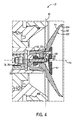
図4は、図1の噴霧システム10の噴霧塗布装置12の部分断面側面図であり、噴霧塗布装置12の流体チップ40の一実施形態を示す。上述したように、噴霧システム10は、流体または空気−流体混合物を、長手方向流体チップ軸72に沿って流体チップ40を通って、流体出口ポート80(fluid exit port 80)の流体出口ポート出口90(fluid exit port outlet 90)から流出し、回転ベルカップ44上に流動させるように構成される。流体または空気−流体混合物は、流体出口軸81に沿って流体出口ポート出口90から出る。図示の実施形態では、流体出口軸81は、長手方向流体チップ軸72および流体チップ通路39を通る(すなわち、流体通路16を通る)流体または空気−流体混合物の流れに略垂直である。加えて、流体出口ポート出口90は、一般に、流体チップ40の側面70と同一平面上にある。流体又は空気−流体混合物が流体出口ポート出口90から出ると、流体又は空気−流体混合物は、一般に、スプラッシュプレート42から離れて、回転ベルカップ44に向かって導かれる。
FIG. 4 is a partial cross-sectional side view of the
回転ベルカップ44は、スプラッシュプレート42に隣接するベルカップ面92を含んでもよい。ベルカップ面92は、内側ベルカップ領域100、中間ベルカップ領域102、及び外側ベルカップ領域104を含んでもよい。内側ベルカップ領域100は、スプラッシュプレート42の後方のベルカップ面92の第1の端部であってもよい。外側ベルカップ領域104は、内側ベルカップ領域100にほぼ対向するベルカップ面92の第2の端部とすることができる。中間ベルカップ領域102は、内側ベルカップ領域100と外側ベルカップ領域104との間のベルカップ面92の一部であってもよい。図示するように、内側ベルカップ領域100は、ほぼ直線状であって、中間ベルカップ領域102に対してある角度で配置され、中間ベルカップ領域102は、ほぼ直線状であって、内側ベルカップ領域100および外側ベルカップ領域104に対してある角度で配置され、外側ベルカップ領域104は、ほぼ直線状である。特定の実施形態では、内側ベルカップ領域100、中間ベルカップ領域102、及び外側ベルカップ領域104は、ほぼ曲線状、放物線状、及び/又は単一の連続曲線を形成することができる。
The
流体出口ポート出口90から出た後、流体または空気−流体混合物は、回転ベルカップ44の内側ベルカップ領域100でベルカップ面92に接触することができる。例えば、流体出口軸81は、流体または空気−流体混合物が流体出口軸81に沿って流体出口ポート出口90から出て、内側ベルカップ領域100で回転ベルカップ44に接触するように、内側ベルカップ領域100と交差してもよい。更に、内側ベルカップ領域100は、内側ベルカップ領域100と流体出口軸81との交点と共に、スプラッシュプレート42の直径によって少なくとも部分的に規定されるベルカップ面92の一部に配置されてもよい。このようにして、流体または空気−流体混合物は、スプラッシュプレート42の直径によって少なくとも部分的に規定される部分(すなわち、回転ベルカップ44とスプラッシュプレート42との間のベルカップ面92の部分でベルカップ面92上に堆積される)で、ベルカップ面92上に堆積されてもよい。
After exiting the fluid outlet port outlet 90, the fluid or air-fluid mixture can contact the
回転ベルカップ44は、一般に、長手方向流体チップ軸72を中心として回転することができる。回転ベルカップ44が回転すると、遠心力によって、内側ベルカップ領域100に接触する流体または空気−流体混合物が、内側ベルカップ領域100からベルカップ面92の中間ベルカップ領域102に向かって流れる。流体または空気−流体混合物は、流体または空気−流体混合物が外側ベルカップ領域104でベルカップ面92から出るまで、回転ベルカップ44のベルカップ面92に沿って続く。次いで、流体(例えば、コーティング材料)または空気−流体混合物を、回転ベルカップ44および噴霧システム10のベルカップ面92を一般的に離れた後に、ターゲットに塗布および/または堆積させてもよい。内側ベルカップ領域100、中間ベルカップ領域102、及び外側ベルカップ領域104の各々は、回転ベルカップ44のベルカップ面92の周囲にまたがるか、又は延びることができる。そのように、回転ベルカップ44が完全な回転を完了するように、流体は内側ベルカップ領域100の全周に接触することができる。流体または空気−流体混合物が外側に流れると、流体または空気−流体混合物は、中間ベルカップ領域102および外側ベルカップ領域104の全周表面領域にわたって流れ続けることができる。
The
上述したように、回転ベルカップ44が回転すると、回転ベルカップ44に負圧が生じ、回転ベルカップ44に隣接する環境からスプラッシュプレート42に向かって回転ベルカップ44内に空気を引き込むことができる。スプラッシュプレート42は、回転ベルカップ44内に引き込まれている空気が、流体出口ポート80から内側ベルカップ領域100の回転ベルカップ44上への流体または空気−流体混合物の流れを乱すのを阻止するように構成することができる。いくつかの実施態様において、流体又は空気−流体混合物は、高速で流体出口ポート80から出てもよい。従来のシステムでは、高速でスプラッシュプレートに向けられた流体または空気−流体混合物が、スプラッシュプレートに摩耗を引き起こす可能性がある。しかしながら、流体又は空気−流体混合物は、本明細書で議論する実施形態のスプラッシュプレート42上に直接分布されないので、スプラッシュプレート42は、従来のシステムと比較して交換される前に、より長い時間持続することができる。
As described above, when the
図5は、図1の噴霧システム10の噴霧塗布装置12の部分断面側面図であり、噴霧塗布装置12の流体チップ40の一実施形態を示す。同様に上述したように、図示された噴霧システム10は、長手方向流体チップ軸72に沿って流体チップ40を通って、それぞれの流体出口ポート82の2つの流体出口ポート出口91から流体または空気−流体混合物を流し、回転ベルカップ44のベルカップ面92上に流すように構成されている。流体または空気−流体混合物は、それぞれの流体出口軸83に沿って流体出口ポート出口91から出る。図示の実施形態では、2つの流体出口ポート82(例えば、第1の流体出口ポートおよび第2の流体出口ポート)は、側面70または流体チップ40の外径からほぼ半径方向外側に突出する。流体出口ポート82は、それぞれの流体出口軸83に沿って(例えば、第1の流体出口軸に沿って、および第2の流体出口軸に沿って)延在してもよい。
FIG. 5 is a partial cross-sectional side view of the
各流体出口ポート82から(各流体出口軸83に沿って)出る流体または空気−流体混合物の流路は、長手方向流体チップ軸72に対してある角度94である。例えば、各流体出口軸83とスプラッシュプレート42に対向する長手方向流体チップ軸72との間の角度94は、一般に鋭角(例えば、89度、88度、87度など)であってもよい。この鋭角は、流体出口ポート82を出る流体または空気−流体混合物が、より滑らかに接触し、内側ベルカップ領域100における回転ベルカップ44のベルカップ面92に沿って流れることを可能にすることによって、ベルカップ面92上への流体または空気−流体混合物の堆積を強化または改善し得る。いくつかの実施形態では、角度94は、ほぼ90度であってもよく、および/または互いにほぼ等しくてもよい。また、各流体出口軸83と長手方向流体チップ軸72との間の角度94は、異なってもよい(例えば、第1の流体出口軸と長手方向流体チップ軸との間の第1の角度、および第2の流体出口軸と長手方向流体チップ軸との間の第2の角度)。
The flow path of the fluid or air-fluid mixture exiting each fluid outlet port 82 (along each fluid outlet axis 83) is at an
流体出口ポート82は、長手方向流体チップ軸72に対して流体チップ40の反対側に配置されてもよく、流体または空気−流体混合物が流体チップ40を離れるときに、流体または空気−流体混合物を内側ベルカップ領域100に向けるように構成されてもよい。流体または空気−流体混合物が流体出口ポート82から出ると、流体または空気−流体混合物は、一般に、スプラッシュプレート42から離れて、回転ベルカップ44に向かって指向される。そのようにして、ベルカップ面92上への流体または空気−流体混合物の堆積を高めることができ、スプラッシュプレート42上の潜在的摩耗を低減することができる。流体または空気−流体混合物は、2つの位置(例えば、内側ベルカップ領域100の2つの位置)で同時にベルカップ面92に接触してもよい。回転ベルカップ44が回転すると、流体または空気−流体混合物は、内側ベルカップ領域100から中間ベルカップ領域102に向かって、中間ベルカップ領域102から外側ベルカップ領域104に向かって、ベルカップ面92に沿って流れ、外側ベルカップ領域104でベルカップ面92から出ることができる。
The
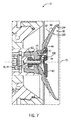
図6は、図1の噴霧システム10の噴霧塗布装置12の部分断面側面図であり、噴霧塗布装置12の流体チップ40の一実施形態を示す。噴霧システム10は、流体または空気−流体混合物を、長手方向流体チップ軸72に沿って流体チップ40を通って、それぞれの流体出口ポート84の2つの流体出口ポート出口93から流出し、回転ベルカップ44のベルカップ面92上に流動させるように構成される。流体または空気−流体混合物は、それぞれの流体出口軸85に沿って流体出口ポート出口93から出る。図示の実施形態では、2つの流体出口ポート84は、概して、流体チップ40の側面70または外側半径方向表面と面一である。各流体出口ポート84から(そのそれぞれの流体出口軸85に沿って)出る流体の流路は、長手方向流体チップ軸72に対して、ある角度95である。例えば、各流体出口軸85とスプラッシュプレート42に対向する長手方向流体チップ軸72との間の角度95は、一般に鋭角である。流体または空気−流体混合物が流体出口ポート84から出ると、流体または空気−流体混合物は、一般に、スプラッシュプレート42から離れて、回転ベルカップ44に向かって指向される。その結果、流体又は空気−流体混合物は、スプラッシュプレート42上に直接堆積されず、これにより、流体又は空気−流体混合物がスプラッシュプレート42上に高速で直接塗布されることによって生じるスプラッシュプレート42上の摩耗及び劣化を低減することができる。流体出口ポート84は、流体チップ40の互いに対して対向する側に配置されてもよく、流体または空気−流体混合物が流体チップ40から離れるときに、流体または空気−流体混合物をベルカップ面92の内側ベルカップ領域100に向けるように構成されてもよい。そのように、流体または空気−流体混合物は、2つの位置(例えば、内側ベルカップ領域100の2つの位置)で同時に回転ベルカップ44に接触することができる。
FIG. 6 is a partial cross-sectional side view of the
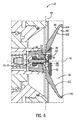
図7は、図1の噴霧システム10の噴霧塗布装置12の部分断面側面図であり、噴霧塗布装置12の流体チップ40の一実施形態を示す。噴霧システム10は、流体または空気−流体混合物を、長手方向流体チップ軸72に沿って流体チップ40を通って、流体出口ポート86の流体出口ポート出口97から流出し、回転ベルカップ44のベルカップ面92上に流動させるように構成される。流体または空気−流体混合物は、流体出口軸87に沿って流体出口ポート出口97から出る。流体または空気−流体混合物が流体出口ポート出口97から出ると、流体または空気−流体混合物は、一般に、スプラッシュプレート42から離れて、回転ベルカップ44に向かって指向される。その結果、流体または空気−流体混合物は、スプラッシュプレート42上に直接堆積されず、それによって、高速でスプラッシュプレート42上に流体を直接塗布することによって生じるスプラッシュプレート42上の摩耗および劣化を低減することができる。図示の実施形態では、流体出口ポート86は、側面70または流体チップ40の外側半径面から外側に突出する。流体出口ポート出口97から(流体出口軸87に沿って)出る流体または空気−流体混合物の流路は、長手方向流体チップ軸72に対して、ある角度96である。例えば、流体出口軸87とスプラッシュプレート42に対向する長手方向流体チップ軸72との間の角度96は、一般に鋭角である。そのように、回転ベルカップ44のベルカップ面92上への流体または空気−流体混合物の堆積は、流体出口ポート86を出る流体または空気−流体混合物が、より滑らかにベルカップ面92に沿って内側ベルカップ領域100で接触し流れることを可能にすることによって改善されてもよい。
FIG. 7 is a partial cross-sectional side view of the
いくつかの実施形態では、図5の流体出口軸83、図6の流体出口軸85、または図7の流体出口軸87は、内側ベルカップ領域100および/または中間ベルカップ領域102に平行であってもよい。流体出口軸83、流体出口軸85、または内側ベルカップ領域100および/または中間ベルカップ領域102に対する流体出口軸87の平行配向は、流体チップ40を出て内側ベルカップ領域100上への流体または空気−流体混合物の堆積を強化し得る。また、平行配向は、内側ベルカップ領域100および/または中間ベルカップ領域102に沿った流体または空気−流体混合物の流れを強化してもよい。
In some embodiments, the
図8は、図1の噴霧システム10の噴霧塗布装置12の部分断面側面図であり、噴霧塗布装置12の流体チップ40の一実施形態を示す。上述のように、噴霧システム10は、流体または空気−流体混合物を、長手方向流体チップ軸72に沿って流体チップ40を通って、それぞれの流体出口ポート88の2つの流体出口ポート出口98から流出し、回転ベルカップ44のベルカップ面92上に流動させるように構成される。流体または空気−流体混合物は、流体出口軸89に沿って流体出口ポート出口98から出る。流体または空気−流体混合物が流体出口ポート出口98から出ると、流体または空気−流体混合物は、一般に、スプラッシュプレート42から離れて、回転ベルカップ44に向かって導かれる。その結果、流体又は空気−流体混合物は、スプラッシュプレート42上に直接堆積されず、これにより、流体又は空気−流体混合物がスプラッシュプレート42上に高速で直接塗布されることによって生じるスプラッシュプレート42上の摩耗及び劣化を低減することができる。図示の実施形態では、2つの流体出口ポート88は、流体チップ40の側面70と略同一平面上にある。各流体出口ポート88から出る(各流体出口軸89に沿った)流体の流路または空気−流体混合物は、長手方向流体チップ軸72に略垂直である。例えば、流体出口軸89と長手方向流体チップ軸72との間の角度は、ほぼ90度であってもよい。流体出口ポート88は、流体チップ40の互いに対して対向する側に配置されてもよく、流体が流体チップ40を離れるときに、流体または空気−流体混合物をベルカップ面92の内側ベルカップ領域100に向けるように構成されてもよい。そのように、流体または空気−流体混合物は、2つの位置(例えば、内側ベルカップ領域100の2つの位置)で同時に回転ベルカップ44に接触することができる。
FIG. 8 is a partial cross-sectional side view of the
噴霧システム12の特定の実施形態は、流体チップの長手方向流体チップ軸に対して、および/またはスプラッシュプレートに対して、角度をなして配置された流体出口ポートを有する流体チップを含んでもよい。例えば、流体チップは、流体チップの円周の周りに等しくまたは非等しく配置された1つ、2つ、3つ、4つ、または複数の流体出口ポートを含んでもよい。流体出口ポートと長手方向流体チップ軸との間の角度は、特定の実施形態の間で変化してもよい。例えば、流体出口ポートは、流体または空気−流体混合物をスプラッシュプレートから逆方向に、そして回転ベルカップに向ける角度であってもよい。流体出口ポートが流体または空気−流体混合物を回転ベルカップの方へ向け、かつスプラッシュプレートから離れるにつれて、流体または空気−流体混合物の回転ベルカップ上への堆積が強化され得、スプラッシュプレート上の潜在的摩耗が低減および/または排除され得る。回転ベルカップおよび/またはスプラッシュプレートに対する流体出口ポートの角度は、特定の実施形態において変化してもよい。更に、スプラッシュプレートは、スプラッシュプレートと回転ベルカップとの間の領域に空気が入るのを阻止して、流体チップを出る流体または空気−流体混合物が、回転ベルカップに沿ってより滑らかに接触して流れることを可能にすることができる。さらに、流体チップのいくつかの実施形態は、噴霧システム12の様々な部分に流体または空気−流体混合物を流すように構成された付加的または他の流体ポートを含んでもよい。
Certain embodiments of the
開示は、様々な改変形態および代替形態を受けやすい場合があるが、特定の実施形態は、図面において例として示されており、本明細書で詳細に説明されている。しかしながら、開示は、開示される特定の形態に限定されることを意図していないことを理解されたい。むしろ、開示は、以下の添付の特許請求の範囲によって定義される開示の精神および範囲にあるすべての修正、均等物、および代替物をカバーすることである。 Although the disclosure may be susceptible to various modifications and alternatives, certain embodiments are shown by way of illustration in the drawings and are described in detail herein. However, it should be understood that the disclosure is not intended to be limited to the particular form disclosed. Rather, disclosure is to cover all modifications, equivalents, and alternatives within the spirit and scope of disclosure as defined by the appended claims below.
Claims (20)
前記噴霧塗布装置の回転ベルカップと、
前記回転ベルカップに連結された前記噴霧塗布装置のスプラッシュプレートと、
前記噴霧塗布装置の流体チップであって、前記回転ベルカップ上に前記流体を出力するように構成された、流体チップと、を備え、
前記流体チップは、
前記流体チップの長手方向流体チップ軸に沿って延在する流体チップ通路であって、前記長手方向流体チップ軸は、前記スプラッシュプレートと交差する、流体チップ通路と、
前記流体チップ通路から前記回転ベルカップ上に前記流体を出力するように構成された第1の流体出口ポートと、を備え、
前記第1の流体出口ポートは、前記流体チップの前記長手方向流体チップ軸に対して第1の角度で配置された第1の流体出口軸に沿って延在する、
噴霧システム。 A spray coating device configured to apply fluid to the target,
The rotating bell cup of the spray coating device and
The splash plate of the spray coating device connected to the rotating bell cup and
A fluid tip of the spray coating apparatus, comprising a fluid tip configured to output the fluid onto the rotating bell cup.
The fluid chip is
A fluid chip passage extending along the longitudinal fluid chip axis of the fluid chip, wherein the longitudinal fluid chip axis intersects the splash plate with a fluid chip passage.
A first fluid outlet port configured to output the fluid from the fluid chip passage onto the rotating bell cup.
The first fluid outlet port extends along a first fluid outlet axis located at a first angle to the longitudinal fluid chip axis of the fluid chip.
Spray system.
噴霧塗布装置の流体チップであって、前記流体チップは、流体を前記噴霧塗布装置の回転ベルカップ上に出力するように構成された、流体チップを備え、
前記流体チップは、
前記流体チップの長手方向流体チップ軸に沿って延在する流体チップ通路と、
前記回転ベルカップ上に前記流体を出力するように構成された流体出口ポートと、を備え、
前記流体出口ポートは、前記流体チップの前記長手方向流体チップ軸に対して、ある角度で配置された流体出口軸を備える、
噴霧システム。 It is a spray system, and the spray system is
A fluid chip of a spray coating device, said fluid tip comprising a fluid tip configured to output fluid onto a rotating bell cup of the spray coating device.
The fluid chip is
A fluid chip passage extending along the longitudinal fluid chip axis of the fluid chip,
A fluid outlet port configured to output the fluid onto the rotating bell cup.
The fluid outlet port comprises a fluid outlet shaft disposed at an angle to the longitudinal fluid chip axis of the fluid chip.
Spray system.
噴霧塗布装置の流体チップの流体チップ通路に沿って流体を流すステップであって、前記流体チップ通路は、前記流体チップの長手方向流体チップ軸に沿って延在するステップと、
流体出口軸に沿って前記流体を流体出口ポートを通って導くステップであって、前記流体出口ポートは、前記流体チップ通路に流体的に連結され、前記流体出口軸は、前記長手方向流体チップ軸に対して、ある角度で配置されるステップと、
前記流体出口ポートから前記流体を回転ベルカップのベルカップ面上に堆積させるステップと、を含む方法。 It ’s a way to activate the spray system.
A step of flowing a fluid along the fluid tip passage of the fluid tip of the spray coating device, wherein the fluid tip passage extends along the longitudinal fluid tip axis of the fluid tip.
A step of guiding the fluid through a fluid outlet port along a fluid outlet shaft, wherein the fluid outlet port is fluidly coupled to the fluid chip passage and the fluid outlet shaft is the longitudinal fluid chip shaft. With respect to the steps arranged at a certain angle,
A method comprising depositing the fluid from the fluid outlet port onto the bell cup surface of a rotating bell cup.
前記ベルカップ面から前記流体を導き出すステップと、
前記流体をターゲット上に堆積させるステップと、を含む、請求項16に記載の方法。 With the step of flowing the fluid along the bell cup surface,
The step of deriving the fluid from the bell cup surface and
16. The method of claim 16, comprising depositing the fluid on a target.
Applications Claiming Priority (5)
| Application Number | Priority Date | Filing Date | Title |
|---|---|---|---|
| US201862715656P | 2018-08-07 | 2018-08-07 | |
| US62/715,656 | 2018-08-07 | ||
| US16/529,585 US11331681B2 (en) | 2018-08-07 | 2019-08-01 | Fluid tip for spray applicator |
| US16/529,585 | 2019-08-01 | ||
| PCT/US2019/045553 WO2020033581A1 (en) | 2018-08-07 | 2019-08-07 | Fluid tip for spray applicator |
Publications (2)
| Publication Number | Publication Date |
|---|---|
| JP2021531968A true JP2021531968A (en) | 2021-11-25 |
| JP7177245B2 JP7177245B2 (en) | 2022-11-22 |
Family
ID=69404949
Family Applications (1)
| Application Number | Title | Priority Date | Filing Date |
|---|---|---|---|
| JP2021506529A Active JP7177245B2 (en) | 2018-08-07 | 2019-08-07 | Fluid chip for spray applicator |
Country Status (5)
| Country | Link |
|---|---|
| US (1) | US11331681B2 (en) |
| EP (1) | EP3833487B1 (en) |
| JP (1) | JP7177245B2 (en) |
| CN (1) | CN113164993A (en) |
| WO (1) | WO2020033581A1 (en) |
Families Citing this family (4)
| Publication number | Priority date | Publication date | Assignee | Title |
|---|---|---|---|---|
| JP7777926B2 (en) * | 2021-03-31 | 2025-12-01 | マツダ株式会社 | Rotating Bell Cup Coating Machine |
| JP7699456B2 (en) * | 2021-03-31 | 2025-06-27 | マツダ株式会社 | Rotating Bell Cup Sprayer |
| EP4351801A4 (en) | 2021-06-09 | 2025-02-26 | Carlisle Fluid Technologies, LLC | Electrostatic atomizer |
| JP7221441B1 (en) * | 2022-07-20 | 2023-02-13 | アーベーベー・シュバイツ・アーゲー | coating equipment |
Citations (5)
| Publication number | Priority date | Publication date | Assignee | Title |
|---|---|---|---|---|
| JPS6086468U (en) * | 1983-11-22 | 1985-06-14 | トリニテイ工業株式会社 | Electrostatic oil applicator |
| JPH02112353U (en) * | 1989-02-28 | 1990-09-07 | ||
| JPH09192544A (en) * | 1996-01-19 | 1997-07-29 | Toyota Motor Corp | Rotary atomizing electrostatic coating equipment |
| JP2008290007A (en) * | 2007-05-24 | 2008-12-04 | Toyota Motor Corp | Rotary atomizing head and rotary atomizing coating equipment |
| JP2009297645A (en) * | 2008-06-12 | 2009-12-24 | Toyota Motor Corp | Rotary atomizing head, rotary atomization coater and rotary atomization coating method |
Family Cites Families (21)
| Publication number | Priority date | Publication date | Assignee | Title |
|---|---|---|---|---|
| GB887450A (en) | 1960-08-03 | 1962-01-17 | Shell Res Ltd | Improvements in and relating to the atomising of liquids |
| BE665065A (en) | 1965-06-24 | |||
| US4458844A (en) | 1977-02-07 | 1984-07-10 | Ransburg Japan Ltd. | Improved rotary paint atomizing device |
| JPS56141867A (en) | 1980-04-04 | 1981-11-05 | Toyota Motor Corp | Rotary atomizing electrostatic coating device |
| US4896834A (en) | 1984-08-30 | 1990-01-30 | The Devilbiss Company | Rotary atomizer apparatus |
| US4785995A (en) | 1986-03-18 | 1988-11-22 | Mazda Motor Corporation | Methods and apparatus for conducting electrostatic spray coating |
| US4919333A (en) | 1986-06-26 | 1990-04-24 | The Devilbiss Company | Rotary paint atomizing device |
| JP2567072B2 (en) * | 1988-12-02 | 1996-12-25 | 株式会社豊田中央研究所 | Rotary atomizing coating device |
| US4943005A (en) | 1989-07-26 | 1990-07-24 | Illinois Tool Works, Inc. | Rotary atomizing device |
| US5934574A (en) | 1995-12-05 | 1999-08-10 | Van Der Steur; Gunnar | Rotary atomizer |
| US6003784A (en) | 1996-04-26 | 1999-12-21 | Gunnar van der Steur | Rotary atomizer with internal chamber |
| US6341734B1 (en) * | 2000-10-19 | 2002-01-29 | Efc Systems, Inc. | Rotary atomizer and bell cup and methods thereof |
| US6557781B2 (en) | 2000-11-30 | 2003-05-06 | Abb K.K. | Rotary atomizing head |
| KR100473034B1 (en) | 2000-12-20 | 2005-03-10 | 에이비비 가부시키가이샤 | Rotary atomizing head type coater |
| JP4554334B2 (en) | 2004-11-08 | 2010-09-29 | トヨタ自動車株式会社 | Rotary atomizing head and rotary atomizing coating equipment |
| JP4750803B2 (en) | 2006-01-19 | 2011-08-17 | Abb株式会社 | Rotary atomizing head type coating equipment |
| CA2688090C (en) | 2007-05-24 | 2014-09-30 | Toyota Jidosha Kabushiki Kaisha | Rotary atomizing head, rotary atomization coating apparatus, and rotary atomization coating method |
| US8602326B2 (en) * | 2007-07-03 | 2013-12-10 | David M. Seitz | Spray device having a parabolic flow surface |
| US10155233B2 (en) | 2008-04-09 | 2018-12-18 | Carlisle Fluid Technologies, Inc. | Splash plate retention method and apparatus |
| US8851397B1 (en) * | 2013-11-14 | 2014-10-07 | Efc Systems, Inc. | Bell cup atomizer having improved cleaning capability |
| KR101634298B1 (en) * | 2016-01-20 | 2016-06-30 | 박상은 | Doule bell-cup |
-
2019
- 2019-08-01 US US16/529,585 patent/US11331681B2/en active Active
- 2019-08-07 CN CN201980062395.9A patent/CN113164993A/en active Pending
- 2019-08-07 WO PCT/US2019/045553 patent/WO2020033581A1/en not_active Ceased
- 2019-08-07 JP JP2021506529A patent/JP7177245B2/en active Active
- 2019-08-07 EP EP19755768.9A patent/EP3833487B1/en active Active
Patent Citations (5)
| Publication number | Priority date | Publication date | Assignee | Title |
|---|---|---|---|---|
| JPS6086468U (en) * | 1983-11-22 | 1985-06-14 | トリニテイ工業株式会社 | Electrostatic oil applicator |
| JPH02112353U (en) * | 1989-02-28 | 1990-09-07 | ||
| JPH09192544A (en) * | 1996-01-19 | 1997-07-29 | Toyota Motor Corp | Rotary atomizing electrostatic coating equipment |
| JP2008290007A (en) * | 2007-05-24 | 2008-12-04 | Toyota Motor Corp | Rotary atomizing head and rotary atomizing coating equipment |
| JP2009297645A (en) * | 2008-06-12 | 2009-12-24 | Toyota Motor Corp | Rotary atomizing head, rotary atomization coater and rotary atomization coating method |
Also Published As
| Publication number | Publication date |
|---|---|
| JP7177245B2 (en) | 2022-11-22 |
| WO2020033581A1 (en) | 2020-02-13 |
| CN113164993A (en) | 2021-07-23 |
| US20200047197A1 (en) | 2020-02-13 |
| US11331681B2 (en) | 2022-05-17 |
| EP3833487A1 (en) | 2021-06-16 |
| EP3833487B1 (en) | 2024-04-03 |
Similar Documents
| Publication | Publication Date | Title |
|---|---|---|
| JP2021531968A (en) | Fluid tip for spray coating equipment | |
| JP6392706B2 (en) | Spraying device having a parabolic flow surface | |
| KR20130107362A (en) | Color selection valve device | |
| CN101479047A (en) | Fluid atomizing system and method | |
| CN102421532A (en) | Projector and member for spraying a coating material, and spraying method using such a sprayer | |
| JP3215873U (en) | Nebulizer | |
| JP7555984B2 (en) | Coating liquid mixing device and coating liquid mixing method | |
| CN107335556B (en) | Mixing valve assembly with atomizing nozzle | |
| KR20000005410A (en) | Wide band applicator of rotary fluid | |
| US8851399B2 (en) | Spraying member, spraying device comprising such a member and spraying installation comprising such a device | |
| JP6046730B2 (en) | Spraying device with curved passage | |
| US6899279B2 (en) | Atomizer with low pressure area passages | |
| JP2003103202A (en) | Swirl gun | |
| JPH07100150B2 (en) | A method for supplying paint to the rotary atomizing head of a sprayer | |
| US6916378B2 (en) | Rotary dispenser and method for use | |
| RU2215592C2 (en) | Device for application of anticorrosive coat on surfaces of steel pipe lines | |
| RU2574244C2 (en) | Spraying device with curvilinear channels | |
| JPS58177166A (en) | Rotary atomizing electrostatic coater | |
| JP2008012469A (en) | Spray apparatus including nozzle on-off valve |
Legal Events
| Date | Code | Title | Description |
|---|---|---|---|
| A621 | Written request for application examination |
Free format text: JAPANESE INTERMEDIATE CODE: A621 Effective date: 20210312 |
|
| A977 | Report on retrieval |
Free format text: JAPANESE INTERMEDIATE CODE: A971007 Effective date: 20220316 |
|
| A131 | Notification of reasons for refusal |
Free format text: JAPANESE INTERMEDIATE CODE: A131 Effective date: 20220329 |
|
| A521 | Request for written amendment filed |
Free format text: JAPANESE INTERMEDIATE CODE: A523 Effective date: 20220628 |
|
| TRDD | Decision of grant or rejection written | ||
| A01 | Written decision to grant a patent or to grant a registration (utility model) |
Free format text: JAPANESE INTERMEDIATE CODE: A01 Effective date: 20221011 |
|
| A61 | First payment of annual fees (during grant procedure) |
Free format text: JAPANESE INTERMEDIATE CODE: A61 Effective date: 20221110 |
|
| R150 | Certificate of patent or registration of utility model |
Ref document number: 7177245 Country of ref document: JP Free format text: JAPANESE INTERMEDIATE CODE: R150 |
|
| R250 | Receipt of annual fees |
Free format text: JAPANESE INTERMEDIATE CODE: R250 |